EP3764272A1 - Système et procédé d'identification d'un objet d'essai - Google Patents
Système et procédé d'identification d'un objet d'essai Download PDFInfo
- Publication number
- EP3764272A1 EP3764272A1 EP19185040.3A EP19185040A EP3764272A1 EP 3764272 A1 EP3764272 A1 EP 3764272A1 EP 19185040 A EP19185040 A EP 19185040A EP 3764272 A1 EP3764272 A1 EP 3764272A1
- Authority
- EP
- European Patent Office
- Prior art keywords
- test object
- test
- pattern
- signature
- test area
- Prior art date
- Legal status (The legal status is an assumption and is not a legal conclusion. Google has not performed a legal analysis and makes no representation as to the accuracy of the status listed.)
- Withdrawn
Links
Images


Classifications
-
- G—PHYSICS
- G07—CHECKING-DEVICES
- G07D—HANDLING OF COINS OR VALUABLE PAPERS, e.g. TESTING, SORTING BY DENOMINATIONS, COUNTING, DISPENSING, CHANGING OR DEPOSITING
- G07D7/00—Testing specially adapted to determine the identity or genuineness of valuable papers or for segregating those which are unacceptable, e.g. banknotes that are alien to a currency
- G07D7/20—Testing patterns thereon
- G07D7/202—Testing patterns thereon using pattern matching
- G07D7/2033—Matching unique patterns, i.e. patterns that are unique to each individual paper
-
- G—PHYSICS
- G06—COMPUTING OR CALCULATING; COUNTING
- G06V—IMAGE OR VIDEO RECOGNITION OR UNDERSTANDING
- G06V10/00—Arrangements for image or video recognition or understanding
- G06V10/20—Image preprocessing
- G06V10/24—Aligning, centring, orientation detection or correction of the image
- G06V10/245—Aligning, centring, orientation detection or correction of the image by locating a pattern; Special marks for positioning
-
- G—PHYSICS
- G06—COMPUTING OR CALCULATING; COUNTING
- G06V—IMAGE OR VIDEO RECOGNITION OR UNDERSTANDING
- G06V10/00—Arrangements for image or video recognition or understanding
- G06V10/20—Image preprocessing
- G06V10/25—Determination of region of interest [ROI] or a volume of interest [VOI]
-
- G—PHYSICS
- G06—COMPUTING OR CALCULATING; COUNTING
- G06V—IMAGE OR VIDEO RECOGNITION OR UNDERSTANDING
- G06V10/00—Arrangements for image or video recognition or understanding
- G06V10/98—Detection or correction of errors, e.g. by rescanning the pattern or by human intervention; Evaluation of the quality of the acquired patterns
- G06V10/993—Evaluation of the quality of the acquired pattern
-
- G—PHYSICS
- G06—COMPUTING OR CALCULATING; COUNTING
- G06V—IMAGE OR VIDEO RECOGNITION OR UNDERSTANDING
- G06V20/00—Scenes; Scene-specific elements
- G06V20/80—Recognising image objects characterised by unique random patterns
-
- G—PHYSICS
- G06—COMPUTING OR CALCULATING; COUNTING
- G06V—IMAGE OR VIDEO RECOGNITION OR UNDERSTANDING
- G06V40/00—Recognition of biometric, human-related or animal-related patterns in image or video data
- G06V40/60—Static or dynamic means for assisting the user to position a body part for biometric acquisition
- G06V40/63—Static or dynamic means for assisting the user to position a body part for biometric acquisition by static guides
-
- G—PHYSICS
- G06—COMPUTING OR CALCULATING; COUNTING
- G06V—IMAGE OR VIDEO RECOGNITION OR UNDERSTANDING
- G06V40/00—Recognition of biometric, human-related or animal-related patterns in image or video data
- G06V40/60—Static or dynamic means for assisting the user to position a body part for biometric acquisition
- G06V40/67—Static or dynamic means for assisting the user to position a body part for biometric acquisition by interactive indications to the user
-
- G—PHYSICS
- G07—CHECKING-DEVICES
- G07D—HANDLING OF COINS OR VALUABLE PAPERS, e.g. TESTING, SORTING BY DENOMINATIONS, COUNTING, DISPENSING, CHANGING OR DEPOSITING
- G07D7/00—Testing specially adapted to determine the identity or genuineness of valuable papers or for segregating those which are unacceptable, e.g. banknotes that are alien to a currency
- G07D7/06—Testing specially adapted to determine the identity or genuineness of valuable papers or for segregating those which are unacceptable, e.g. banknotes that are alien to a currency using wave or particle radiation
- G07D7/12—Visible light, infrared or ultraviolet radiation
-
- G—PHYSICS
- G07—CHECKING-DEVICES
- G07D—HANDLING OF COINS OR VALUABLE PAPERS, e.g. TESTING, SORTING BY DENOMINATIONS, COUNTING, DISPENSING, CHANGING OR DEPOSITING
- G07D7/00—Testing specially adapted to determine the identity or genuineness of valuable papers or for segregating those which are unacceptable, e.g. banknotes that are alien to a currency
- G07D7/17—Apparatus characterised by positioning means or by means responsive to positioning
Definitions
- the present invention relates to an object identification system for identifying a test object.
- the present invention also relates to a method for identifying a test object.
- Systems for identifying test objects are used on various occasions. Such systems are used, for example, in the field of logistics, that is, where a certain object is to be moved from one location to another. Such systems are also used in industrial production, for example when processed semi-finished products are to be fed to subsequent processing steps. Such systems are also used in areas in which the authentication of a test object is to be successful.
- Stickers have been known for a long time to identify a test object in the field of logistics. These stickers are stuck on the test object and can be clearly identified, for example a QR code or a so-called RFID tag.
- the disadvantage here is that such a sticker must first be applied to the test object and removed again after the test object has been identified in order to restore the original state of the test object. When removing, adhesive residues often remain on the test object. Furthermore, the removal of stickers is particularly time-consuming.
- the US4641349A discloses a system and method for identifying a person by the iris of their eyes.
- stored data from the pupil and iris of a person are compared with the data from an image of a pupil and iris. If the compared data are the same, the person is considered identified.
- the disadvantage of this system and method is that only unchangeable objects, such as an iris, can be compared with one another. If the object to be authenticated is subject to natural changes or changes caused by third parties, this solution will fail.
- the object of the invention is to make a system and a method for object identification of the type mentioned at the beginning more efficient.
- the object identification system has an object detection unit and a computer-aided evaluation unit connected to it.
- the object detection unit according to the invention is designed and set up to detect a pattern of a test object from at least one side. This detection of the pattern takes place in points, lines or areas.
- An object detection unit is preferably formed by a camera that detects the pattern in terms of area.
- test object in the sense of the present invention is an object to be identified.
- This object is unchangeable or changeable in its appearance, i.e. the object can be subject to physical changes over time, for example through processing or aging.
- the test object is checked completely or only in sections, for example in a dot-like manner, from at least one side of the test object.
- a test object is preferably made up of raw materials, processed industrial semi-finished and finished goods, data carriers such as paper-based documents and literature, art objects such as sculptures, pictures or photographs, unprocessed and processed wood and wood products, paper or cardboard or products made from them, luxury products such as watches or jewelry, Textiles of all kinds, means of payment such as coins and notes as well as card-based means of payment, furniture such as tables, chairs, cupboards or lamps, medicines, medicine packaging or food.
- data carriers such as paper-based documents and literature, art objects such as sculptures, pictures or photographs, unprocessed and processed wood and wood products, paper or cardboard or products made from them, luxury products such as watches or jewelry, Textiles of all kinds, means of payment such as coins and notes as well as card-based means of payment, furniture such as tables, chairs, cupboards or lamps, medicines, medicine packaging or food.
- data carriers such as paper-based documents and literature, art objects such as sculptures, pictures or photographs, unprocessed and processed wood and wood products, paper or cardboard or products made from them
- the test object is also formed by a sticker or packaging.
- the sticker or the packaging is not part of the object to which it is applied or which at least partially surrounds it.
- a test object is not formed by a pallet.
- a pallet is an arrangement for the transport, storage and / or bundling of an object or several objects and is characterized by a flat construction and can usually be stacked to save space.
- a pallet is made of wood, plastic, metal, cardboard or a combination of the aforementioned materials.
- a pallet often has lateral recesses in order to be able to transport it with the aid of a floor conveyor, for example a forklift.
- the test object is not formed by a so-called Euro pallet.
- a pattern is a component of the test object which is detected with the aid of the object detection unit.
- the pattern cannot be separated from the test object without the pattern and / or the test object being destroyed or at least one of the two being greatly changed in its essence.
- the sample is not to be regarded as independent, but as belonging to the test object.
- a pattern is, for example, a corner, an edge, a certain angle, a letter, a number, a character.
- a pattern is preferably a grain, a height-depth profile, a surface structure, a line, a line combination, a color, a color combination, a gray value, a gray value combination, a color gradient, a gray value gradient or a combination of two or more of the aforementioned features.
- a pattern is formed by the grain of a wood or wooden material, a fine structure of paper or cardboard, a structure of a metal or plastic surface.
- the test object of the first pattern detection and the test object of the second pattern detection can be identical to or different from one another within the meaning of the invention.
- the differences between the two aforementioned test objects, i.e. with the first and second sample acquisition, can be the result of a deliberate or unintentional processing or modification of a test object between the two aforementioned sample acquisitions.
- the first pattern acquisition of the pattern regularly takes place before the second pattern acquisition of the pattern.
- the object detection unit detects the pattern of the test object and at least one test object feature and generates test object data therefrom.
- a test object feature of the test object is recorded during the pattern detection.
- a test object feature is a characteristic feature of a test object such as a corner, an edge, a certain angle, a hole, a groove, a letter, a number, a character, a grain, a height-depth profile, a surface structure, a line, a Line combination, a color, a color combination, a gray value, a gray value combination, a color gradient, a gray value gradient, the partial or complete outer contour of the test object, the center of a two- or three-dimensional section of the test object or a combination of two or more of the aforementioned features.
- the test object feature is preferably a permanent feature.
- test object feature can only be identified with the aid of further measures, for example by means of UV irradiation.
- At least one further test object feature of the test object is recorded in the pattern acquisition. This is relevant, among other things, if, for example, the test object is subjected to a processing process and a first test object feature has been changed, damaged or removed as a result of this processing process. In such a case, the test object position and the test area are determined using at least one further test object feature. This enables a determination of correspondence or discrepancy between two test objects in the event of damage, change or removal of a test object feature. In such a case of changing, damaging or removing a first test object feature, the determination of a test area is still possible with the aid of the further test object feature and thus opens up the possibility of signature generation and signature comparison.
- test object features therefore offers a higher probability of identifying a test object.
- the object detection unit is connected to a computer-aided evaluation unit.
- the computer-aided evaluation unit is designed and set up to receive test object data from the object detection unit and to process and provide this.
- the processing of the test object data consists only in storing this test object data.
- test object data from the detection of the pattern of the test object contain the position data of the object detection unit implicitly or explicitly.
- the explicit position data of the object detection unit are those position data which the object detection unit detects and provides, for example with the aid of sensors such as GPS or inclination sensors. Such data include the absolute position of the object detection unit and its inclination in the spatial directions.
- the position data of the object detection unit relative to the pattern of the test object are implicitly contained in the test object data, since the detected pattern can only be detected in this way in a single position of the object detection unit in relation to the pattern.
- a test object position is determined by a position identification unit.
- the test object position is determined by the pose of the test object relative to the object detection unit.
- the pose of the test object is the combination of position and orientation of the test object in three-dimensional space.
- the test object position of the test object is determined in particular by determining data which describe the position, size and image definition of the test object feature.
- the orientation of the test object feature can also be used to determine the test object position.
- the same test object feature is used to determine the test object position of the test object in the first and in the second sample capture.
- the data that describe the position of the test object from the first sample acquisition are saved.
- the data which describe the test object position of the first pattern acquisition of the test object are stored as the reference test object position.
- the reference test position is used to determine its test object position, in that the test object position of the newly acquired test object is determined in relation to the reference test position.
- the test object feature is not formed by the pattern or a part of the pattern. This means the test object feature and pattern differ from one another. In such an embodiment of the invention, the test object feature is formed, for example, by an edge of the test object and the pattern, for example, by a grain.
- the test object feature is formed from the combination of section-wise or complete test object feature itself, for example a combination of letters, and section-wise or complete pattern, for example a grain.
- the above-described combination of test object feature and pattern is used to determine the test object position of the test object and to determine the test area and the test area signature.
- the test object feature is partially or completely formed from the pattern.
- a height-depth profile on the test object forms both the pattern and the test object feature.
- a test object with a stationary object detection unit is positioned in the same pose relative to the object detection unit during the second pattern detection, that is, in the same test object position as in the first pattern detection.
- the evaluation of the test object feature for determining the test object position of the test object and thus also the use of the position identification unit is dispensable.
- the position identification unit can be deactivated. This is the case, for example, when the object detection unit is arranged statically opposite the test object and the test objects, as already described, are always arranged in the same pose to the object detection unit, for example on a conveyor belt on which the test objects are arranged accordingly. In such a case, the test object feature is only used to determine the test area.
- a test area is determined on the sample with the aid of a test object feature.
- An inspection area is an area that extends on the pattern of the inspection object.
- the test area extends along a test area boundary on the sample.
- the test area is regularly virtual, not permanent in nature.
- the test area can assume various geometric shapes.
- the test area extends from a test area origin along defined test area coordinates or a defined test area dimension on the pattern.
- test area is rectangular. In another embodiment of the invention, the test area is round.
- a test object feature is used to determine a test area on the sample of the test object and / or to determine the test object position of the test object.
- a signature generator generates signature data from the test object data. To this end, those test object data that lie within the test area are first extracted from the test object data. These extracted test object data form the signature data. A test area signature is then generated from this signature data by the signature generator. In other words, the signature data are, so to speak, cut out of the test object data in accordance with the test area limits. The signature generator forms the test area signature from this signature data.
- the test area extends only in sections on the pattern. This has the advantage that the test object data of the entire surface of the pattern or even of the entire test object do not have to be processed.
- a test area signature regularly summarizes individual characteristics of a sample of the test area in a compressed representation. It is regularly made up of a sequence of numbers, letters and / or characters.
- a test area signature is preferably formed from a sequence of zeros and ones.
- the individual characteristics of a pattern summarized by a test area signature are a grain, a height-depth profile, a surface structure, a line, a line combination, a color, a color combination, a gray value, a gray value combination, a color gradient, a gray value gradient but also a corner, a Edge, a certain angle, a letter, a number, a character, a plurality of one of the aforementioned features or a combination of two or more of the aforementioned features.
- each test area signature generated by the signature generator is stored.
- the test area signature is provided with an identifier so that each test area signature can be identified.
- the inspection area signature is stored together with the identifier.
- an identifier is a unique identifier of a test area signature that occurs only once.
- Such an identifier preferably consists of letters, numbers, characters or a combination thereof.
- an identifier is assigned to a product or article. This provision of the test area signature with an identifier is used, among other things, for the traceability of a test object, for example in the context of quality management.
- the signature comparison unit compares the test area signature of the pattern of a first pattern detection with the test area signature of the pattern of a second pattern detection and generates a signature deviation therefrom. For this it is necessary that the test area is determined in the second sample acquisition in the same test object position as in the first sample acquisition. The signature deviation is classified by the signature classification unit.
- test area signatures are compared which are determined from test areas which have the same geometric design and the same area.
- test areas of different size are compared with one another.
- the smaller test area of a pattern detection is determined in the larger test area of another pattern detection and then the two test areas which are the same in area and dimensions are compared with one another.
- the test area signature of a second pattern detection is used as a reference when the test object is detected again.
- An updated test area signature is therefore actually obtained, which can be used as a reference for a subsequent identification of the test object.
- the The test area signature can be updated in the production / processing process. Even when the test object ages, the test area signature can, so to speak, "age" parallel to the test object and also enables the identification of an aged test object.
- the signature classification unit classifies the signature deviation using at least one signature threshold value, for example using statistical methods.
- a suitable signal threshold value is, for example, the similarity of the test area signature of a test object to the totality of the test area signatures of all other test objects. If the signature deviation of the test object to be identified is below that of the signature threshold value, which is still defined as sufficient, the signature deviation is to be regarded as small and the test object is regarded as identified. If, on the other hand, the signature deviation of the test object to be identified is above that of the signature threshold value that is still defined as sufficient, then the signature deviation is to be regarded as large and the test object is regarded as not identified.
- the signature classification of a successful identification of a test object takes place as follows.
- the test area signature of the test object to be identified is compared with all available test area signatures. This is done in two steps. First step: If the signature deviation of two test area signatures is below the threshold value which is still defined as sufficient, then these two test area signatures are similar. Second step: This test area signature, identified as similar, must be dissimilar to the other test area signatures, i.e. the signature deviation from the other test area signatures must be well above the threshold value.
- the computer-aided evaluation unit is connected to a signaling unit.
- the signaling unit signals a signature deviation classified by the signature classification unit.
- a signature deviation classified as sufficient or no longer sufficient is signaled, for example by “signature recognized” or “signature not recognized” or “test object identified” or “test object not identified”.
- the signaling unit signals that the test area of the second pattern detection matches the test area of the first pattern detection, for example by displaying "test area ok” or “test area found” or a discrepancy between the test area of the second pattern detection and the test area of the first pattern detection by displaying "test area not ok” or "test area not found”.
- test area of the second pattern detection In order for the test area of the second pattern detection to show a match with the test area of the first pattern detection, a prerequisite is that both test areas are determined in the same test object position. A slight deviation in the test object position in the first and second sample acquisition is still considered to be the same test object position. A slight deviation in the position of the test object is in particular a deviation of a few percent.
- the deviation in the test object position in the first and second pattern detection is classified by means of a threshold value. Below this threshold value, a deviation in the test object position in the first and second sample acquisition is still considered to be minor and thus as the same test object position and above this threshold value the test object position is considered different.
- the signaling unit is designed and set up in such a way that it signals which operations are to be carried out in order to find the matching test area, for example by indicating "to the left” or “to the right”, “upwards” or “after” below “,” rotate clockwise “or” rotate counterclockwise “,” reduce distance “or” increase distance "or a combination of at least two of the aforementioned.
- the signaling unit is designed and set up in such a way that it signals the test area deviation, the test area match, the signature deviation, the signature match or a combination of at least two thereof.
- the signaling takes place in particular by means of an optical signal, an acoustic signal, an electrical signal, a haptic signal, for example in the form of a vibration, or a combination of two or more thereof.
- the position identification unit, the test area determination unit, the signature generator, the signature comparison unit and the signature classification unit are part of the computer-aided evaluation unit.
- the components of the computer-aided evaluation unit can run individually or in combination of at least two components on separate systems.
- the position identification unit can be deactivated.
- test object identification works as follows: To identify a test object, this test object is recorded by means of an object detection unit and the test object data is generated therefrom.
- An area camera serves as the object detection unit. In this detection, it is preferred not to detect the entire test object, but rather only a sample of the test object. This sample is part of the test object.
- the test object can also be a sticker.
- These test object data are transferred to the computer-aided evaluation unit and processed and made available by it.
- This computer-aided evaluation unit has a position identification unit, a test area determination unit, a signature generator, a signature comparison unit and a signature classification unit.
- the position identification unit determines the position of the test object on the basis of a characteristic feature of the test object, here called test object feature.
- the test object position is characterized by the pose of the pattern of the test object relative to the object detection unit. Furthermore, the inspection area determination unit determines an inspection area on the pattern with the aid of an inspection object feature. This test area extends along a test area boundary on the sample. The signature generator extracts signature data from the test object data that lie within this test area and generates a test area signature from this signature data. The signature comparison unit finally compares the test area signature of the pattern of a first pattern acquisition with the test area signature of the pattern of a second pattern acquisition. A signature deviation is generated from the comparison result. For the comparison of two test area signatures, it is necessary that the test area of the pattern of the second pattern detection is determined in the same test object position as the test area from the first pattern detection. A slight deviation in the test object position in the first and second sample acquisition is still considered to be the same test object position.
- test object feature which was used in the first sample acquisition to determine the test object position is no longer present, then another test object feature is used to determine the test object position and test area used. This further test object feature is contained in the test object data of the first sample acquisition and the second sample acquisition.
- test object detection units In order to clearly identify a test object, it is therefore not necessary to record the entire test object, but only a sample and that only in sections. This leads to smaller amounts of data to be processed and thus to higher speeds in the identification of a test object. This is particularly important against the background that modern object detection units have a very high resolution and thus produce large amounts of data.
- test area signature is stored together with further data.
- Further data are relevant data such as place, date and time. These data are stored under the identifier of this test area signature or as separate entries.
- An advantageous embodiment of the object identification system is characterized in that the object detection unit is designed as part of a mobile terminal.
- a mobile terminal device within the meaning of the invention can be carried without major physical exertion and can therefore be used in a mobile manner.
- a terminal can be connected to a data or telecommunications network. It is designed, for example, as a mobile data acquisition unit, such as a mobile phone, a smartphone, a smart watch, a tablet PC, a notebook, an imager or a combination of at least two of the aforementioned.
- An imager is a mobile camera with integrated lighting.
- the mobile terminal is connected to a data and / or telecommunications network permanently or over a certain period of time.
- test area signatures are stored locally on the mobile terminal, in particular those test area signatures which are expected to be used and / or required. This enables the object identification system to be used without a permanent connection to a data or telecommunications network.
- An advantageous embodiment of the object identification system is characterized in that the test area is determined with the aid of a provided CAD model of the test object.
- the CAD model is provided to the test area determination unit, for example with the aid of a database, a storage medium or another suitable transmission method.
- the CAD model provided contains a test area delimited by a test area delimitation.
- Image property components are preferably formed from image sharpness, image brightness, image contrast, distortion, color gradient, gray values, position or rotational position or a combination of at least two of the aforementioned.
- the image property components mentioned above are only exemplary and not exclusive.
- a target quality vector contains the minimum requirements for image information which are at least necessary for further image processing.
- the target quality vector contains only the image information suitable for assessing the image quality, in particular Information on image sharpness, image brightness, image contrast, distortion, rotational position, or color gradient as well as other image features common in image processing or a combination of several of the above. These minimum requirements are mostly due to technical reasons and / or are specified, for example by the user of the system.
- An actual quality vector contains the information contained in the test object data, i.e. actual information on image property components such as image sharpness, image brightness, image contrast, distortion, rotational position or color gradient or a combination of several of the aforementioned.
- the target quality vector contains the target values of the required image property components and the actual quality vector contains the actual values of the image property components, more or less like a certificate.
- the quality threshold value vector contains the quality differences of the image property components, which were formed from the pairwise comparison of the image property components of the target quality vector and the actual quality vector.
- the signaling unit is designed and set up in such a way that it displays in particular the test area deviation, the quality difference, the signature deviation or a combination of at least two thereof.
- An advantageous embodiment of the object identification system is characterized in that the image quality assurance unit displays the quality difference of an image property component. If the quality difference of an image property component is below a defined quality threshold value, this image property component is considered to be qualitatively sufficient for further use, in particular for determining the test object position. This quality threshold is defined depending on the test object.
- the image quality assurance unit also provides information on correcting the image quality in addition to the quality difference.
- Such instructions are, for example, positioning instructions for the object detection unit and / or the test object, in particular instructions such as moving, rotating and / or reducing or increasing the distance between the object detection unit / test object.
- An advantageous embodiment of the object identification system is characterized in that the image quality assurance unit corrects an image property component of the actual quality vector until the quality difference of this image property component is below a quality threshold value.
- the image quality assurance unit detects that the quality difference is based on a rotation in the plane of the pattern of the second pattern detection compared to the pattern of the first pattern detection.
- the image quality assurance unit corrects the test object data by means of an algorithm in such a way that the test object data of the pattern of the second pattern acquisition are rotated until the rotation compared to the pattern of the first pattern acquisition is so small that the quality difference is below the quality threshold value qualified as sufficient.
- These rotated test object data i.e. adapted according to the rotation of the pattern, are then used to determine the test area, to obtain the signature data from it and then to obtain the test area signature.
- the image quality assurance unit rotates the test object data of the pattern of the second pattern detection into the position of the pattern of the first pattern detection. The prerequisite for this is that these two patterns are in one plane or approximately in one plane.
- the image quality assurance unit detects that the quality difference is based on a shift in the plane of the pattern of the second pattern detection compared to the pattern of the first pattern detection.
- the image quality assurance unit corrects the test object data by means of an algorithm in such a way that the test object data of the pattern of the second pattern acquisition are shifted until the shift compared to the pattern of the first pattern acquisition is so small that the quality difference is below the quality threshold value qualified as sufficient.
- These displaced test object data that is to say adapted according to the displacement of the second pattern, are then used to determine the test area, to obtain the signature data therefrom and then to obtain the test area signature.
- the Image quality assurance unit shifts the test object data of the pattern of the second pattern detection into the position of the pattern of the first pattern detection. The prerequisite for this is that these two patterns are in one plane or approximately in one plane.
- the image quality assurance unit detects that the quality difference is based on a difference in distance between the pattern of the second pattern detection and the pattern of the first pattern detection, both patterns being arranged parallel or approximately parallel to one another.
- the image quality assurance unit corrects the test object data of the second pattern acquisition using an algorithm by moving the test object data of the second pattern acquisition into the position until an image sharpness is achieved that is below a certain threshold value which is defined as sufficient image sharpness. Small deviations in the parallelism of the two patterns are also covered by the inventive concept.
- the aforementioned difference in distance is corrected by means of zooming.
- the image quality assurance unit detects that the quality difference is based on a distance difference, a rotation, a displacement and / or an inclination in the plane of the pattern of the second pattern detection compared to the pattern of the first pattern detection.
- the image quality assurance unit uses a signal to request the correction of the rotation, the displacement, the difference in distance and / or the misalignment in the plane of the second pattern detection by correcting the position of the object detection unit and / or the test object.
- the aforementioned signal can be an electrical signal to a partially / fully automated handling system such as a robot or a graphic signal for a human user, for example in the case of a hand-held mobile terminal.
- the adjustment of the position of the object detection unit and / or the pattern of the second pattern detection is repeated until the quality difference falls below the defined quality threshold value.
- the image quality assurance unit detects that the quality difference is based on a difference in distance or a rotation or displacement of the pattern of the second pattern detection compared to the pattern of the first pattern detection and an inclination in the plane of the two aforementioned patterns to one another.
- the inclination of the two patterns with respect to one another in the plane is initially determined by a partially / fully automated handling system or corrected by the user. The rotation or displacement in the plane or the parallel displacement in distance of the pattern of the second pattern detection is then corrected by means of an algorithm.
- first the rotation or displacement in the plane or the parallel displacement of the pattern of the second pattern detection is corrected by means of an algorithm and then the misalignment of the two aforementioned patterns to one another in the plane by a partially / fully automated handling system or by the User corrected.
- An advantageous embodiment of the method for identifying a test object is characterized by displaying the quality difference of an image property component.
- An advantageous embodiment of the method for identifying a test object is characterized by correcting an image property component of the actual quality vector until the quality difference of this image property component is below a quality threshold value.
- the image property component of the actual quality vector is corrected by the user himself or with the aid of an algorithm.
- the aim is to identify a test object 12.
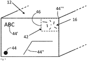
- the Figure 1 shows a schematic representation of a test object 12 with a rectangular area.
- test object features 44, 44 ', 44 ", 44'” are shown by way of example.
- the test object feature 44 is formed here by a round bore shown here as a circle, the test object feature 44 'is formed by the letter sequence "ABC”, test object feature 44 "is formed by two grooves, shown here as lines, connected to one another at a flat angle and that Test object feature 44 '"is formed by the right upper corner of the illustrated rectangular area with a right angle.
- a pattern 16 is shown in the right upper area of the rectangular area of the test object 12.
- the pattern 16 is part of the in all illustrated embodiments Test object 12 and thus not separable from the test object without the pattern 16 or the test object 12 being destroyed or at least one of the two being changed in its essence.
- the pattern 16 is formed here by a height-depth profile shown by lines on the surface of the test object 12. This height-depth profile is, for example, the grain of a wooden surface, the fine structure of paper, cardboard or a plastic surface, the rough surface of a metallic cast part or a semi-finished product before or after a machining step, for example before or after milling.
- test area 42 which surrounds the entire surface of the pattern 16, extends on the pattern 16.
- the test area 42 is delimited by a test area delimitation 46.
- the test area 42 extends in a rectangular shape from an origin along the area enclosed by the test area delimitation 46. In one in the Figure 1 In the case not shown, the test area 42 extends only partially on the pattern 16.
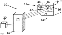
- the Figure 2 shows a schematic representation of an embodiment of an object identification system 10 according to the invention for testing the test object 12.
- the object identification system 10 shown comprises an object detection unit 14 and a computer-aided evaluation unit 20 connected to this object detection unit 14.
- the object detection unit 14 is formed here by an area camera or a mobile terminal device a camera. In the case shown here, this object detection unit 14 is connected to an external computer-aided evaluation unit 20 via a data connection.
- the test object 12 described takes place as follows:
- the object detection unit 14 detects the already described pattern 16 of the test object 12 and the test object features 44, 44 ', 44 ". 44"'.
- test object data 18 (not shown here). These test object data 18 are processed in further units not shown here. Since the detected pattern can only be detected in this way in a single position of the object detection unit in relation to the pattern, a test object position can be determined by detecting, for example, position, size and image sharpness of one of test object features 44, 44 ', 44 ", 44'” . This test object position is formed from the pose of the test object 12 relative to the object detection unit 14.
- test object position of the test object 12 is shown in Figure 2 based on the position, size and image sharpness of the test object feature 44 "', that is to say the upper right corner of the test object 12.
- the Figure 3 shows the test object 12 from Figure 2 for example after a processing step.
- Test object data 18 described are here transferred to the computer-aided evaluation unit 20.
- test object data 18 ' is that in this case the test object feature 44, that is, the hole represented by a point, is no longer present because the lower left corner of the test object 12 was removed, for example, in a milling step.
- test object features 44 ′, 44 ′′, 44 ′ ′′ are available, which are now used to determine the test object position of the test object 12. This shows the advantages of recording multiple test object features. If only the test object mark 44 had been recorded before the processing, the determination of the test object position of the test object 12 in the manner described would no longer succeed.
- test object position of the test object In contrast to the use of only one test object feature to determine the test object position of the test object, the use of several test object features enables the test object position to be determined even if a test object feature is no longer present or damaged.
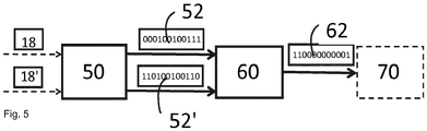
- the Figure 4 shows in a schematic sequence how a signature deviation 70 is generated from test object data 18 and 18 '.
- a position identification unit not shown here, receives the test object data 18 or 18 '.
- the test object data 18 are obtained from a first pattern acquisition of the pattern, while the test object data 18 'are obtained from a second pattern acquisition of the pattern.
- the test object data 18 contain the data on the position, size and image sharpness of a detected test object feature of the first test object as well as data of a recorded pattern of this first test object.
- the position identification unit stores data which describe the pose of the first test object and the relative position of the object detection unit, not shown here, to the test object.
- This first pose, together with the relative position of the object detection unit, also not shown here, to the test object forms a first test object position.
- a test area determination unit determines a test area.
- test area is determined along the test area boundaries (not shown here), virtually placed on the sample of the test object, so to speak.
- the test area boundaries enclose the test area on the sample. All test object data that are not enclosed by the test area limits are discarded.
- the test object data which are enclosed by the test area boundaries, ie lie within the test area, are further processed as signature data, not shown here, of the sample of the test object.
- a signature generator 50 generates a test area signature 52 from this signature data. This test area signature 52 depicts the characteristics of the detected pattern in a combination of suitable characters.
- test object data 18 'contain the data on the position, size and image sharpness of a recorded test object feature of the second test object as well as data of a recorded pattern of this second test object.
- test object feature nor test object or pattern of the second pattern detection are shown.
- the position identification unit determines the position of the test object of the second test object from the data on the position, size and image definition of the test object feature of this second sample recording.
- the test object position of the second test object is not determined as an absolute test object position, but in relation to the test object position of the first test object, thus as a relative test object position. So that the test area of the pattern of the second pattern detection can be determined in the same test object position of the test object as the test area of the pattern of the first pattern detection, it is necessary that the first test object position and second test object position are the same or approximately the same. Only when the deviation from the first and second test object position falls below a certain threshold value is a test area determined on the pattern of the second test object.
- the determination of the test area on the pattern of the second test object and a test area signature takes place analogously to the generation of the already described above Test area of the pattern of the first test object.
- the test area signature 52 'is thereby obtained.
- This signature comparison takes place in a signature comparison unit 60.
- the signature comparison unit 64 delivers a signature deviation 62 as a result.
- This signature deviation 62 is classified using at least one threshold value in a signature classification unit 70 .
- a suitable threshold value is the similarity of the test area signature of a test object to the totality of the test area signatures of all test objects.
- the signature deviation is below that of the signature threshold value, which is still defined as sufficient, then the signature deviation is to be regarded as low and the test object is regarded as identified. If, on the other hand, the signature deviation is above that of the signature threshold value that is still determined to be sufficient, then the signature deviation is to be regarded as large and the test object is regarded as not identified.
- the Figure 5 shows an example of the result of the signature deviation from the signature comparison Figure 4 .
- the test area signatures 52 and 52 'reproduced by way of example are compared with one another.
- the result of this signature comparison in the signature comparison unit 60 is the signature deviation 62 reproduced by way of example, which in turn, as already shown Figure 4 is classified by the signature classification unit 70.
- the Figure 6 shows two detected patterns 16 and 16 'in different image quality.
- the pattern 16 is captured without distortion with a first image sharpness.
- the pattern 16 ' shows distortions, so that the individual elements of the pattern 16' appear thicker.
- the inadequate image sharpness of the pattern 16 ' is here a consequence, for example, of an insufficient distance between the object detection unit and the pattern 16'.
- either the user is requested to move the object detection unit or the test object with the pattern 16 in such a way until an image sharpness is achieved which is below a certain threshold value which is defined as sufficient image sharpness
- the test object data of the detected pattern 16 are an algorithm 'processed until an image sharpness is achieved that is below a certain threshold value, which is defined as sufficient image sharpness.
- the Figure 7 shows three patterns 16, 16 ', 16 ′′ recorded at different angles of rotation, all of which lie in one plane.
- the pattern 16 is recorded without rotation, that is to say with a rotation angle of 0 °.
- the pattern 16' is 60 ° compared to the pattern 16
- the pattern 16 ′′ is opposite to the pattern 16 by 40 ° Twisted clockwise.
- the position identification unit (not shown here) recognizes the rotation of the patterns 16 'and 16 "with respect to the pattern 16.
- the test area is classified as not recognized or not found.
- the user is then prompted either to use the object detection unit or the test object with the pattern 16 to rotate until the rotation reaches a threshold value classified as sufficient, i.e.
- Threshold value i.e. a rotation of approximately 0 °
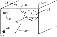
- the Figure 8 shows the test object Figure 1 with one opposite Figure 1 enlarged pattern 16.
- This figure shows that in one embodiment the test area 42 extends only in sections on the pattern 16, i.e. the test area 42 is smaller than the detected pattern 16. This has the advantage that the amount of data to be processed is less than the test area 42 would encompass the area of the entire pattern 16.
- the Figure 9 shows the test object Figure 1 with one opposite Figure 1 additional sample and test area.
- a pattern when a pattern is detected, not only a pattern 16 is detected, but also a further pattern 16 '.
- the further pattern 16 ' is processed further in accordance with the steps already described and a test area signature (not shown here) is generated therefrom. This expands the possibility of identifying a test object that is subject to changes, for example through processing steps.
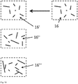
- the Figure 10 shows an example of the pattern comparison based on signature comparison of a pattern 16 with three patterns 16 ', 16 ", 16"' already recorded.
- the pattern 16 recorded last is compared with three patterns 16 ′, 16 ′′, 16 ′ ′′ recorded in the past.
- a test area signature not shown here, which was generated from the pattern 16
- three test area signatures also not shown here, which were previously generated from the patterns 16 ', 16 "and 16'”.
- the signatures of these patterns are compared in pairs. This means that the signature comparison of the samples 16 and 16 'takes place, then the signature comparison of the samples 16 and 16 "and then the signature comparison of the samples 16 and 16"'. It is crucial here that the pattern 16 with all three others Patterns 16 ', 16 "and 16'” is compared, wherein the order of the compared signature pairs can vary.
Landscapes
- Engineering & Computer Science (AREA)
- Physics & Mathematics (AREA)
- General Physics & Mathematics (AREA)
- Multimedia (AREA)
- Theoretical Computer Science (AREA)
- Human Computer Interaction (AREA)
- Quality & Reliability (AREA)
- Computer Vision & Pattern Recognition (AREA)
- Health & Medical Sciences (AREA)
- General Health & Medical Sciences (AREA)
- Toxicology (AREA)
- Image Analysis (AREA)
Priority Applications (1)
| Application Number | Priority Date | Filing Date | Title |
|---|---|---|---|
| EP19185040.3A EP3764272A1 (fr) | 2019-07-08 | 2019-07-08 | Système et procédé d'identification d'un objet d'essai |
Applications Claiming Priority (1)
| Application Number | Priority Date | Filing Date | Title |
|---|---|---|---|
| EP19185040.3A EP3764272A1 (fr) | 2019-07-08 | 2019-07-08 | Système et procédé d'identification d'un objet d'essai |
Publications (1)
| Publication Number | Publication Date |
|---|---|
| EP3764272A1 true EP3764272A1 (fr) | 2021-01-13 |
Family
ID=67296971
Family Applications (1)
| Application Number | Title | Priority Date | Filing Date |
|---|---|---|---|
| EP19185040.3A Withdrawn EP3764272A1 (fr) | 2019-07-08 | 2019-07-08 | Système et procédé d'identification d'un objet d'essai |
Country Status (1)
| Country | Link |
|---|---|
| EP (1) | EP3764272A1 (fr) |
Citations (8)
| Publication number | Priority date | Publication date | Assignee | Title |
|---|---|---|---|---|
| US4641349A (en) | 1985-02-20 | 1987-02-03 | Leonard Flom | Iris recognition system |
| US5673338A (en) * | 1993-06-10 | 1997-09-30 | Verification Technologies, Inc. | System for verification of unique items |
| WO2005088533A1 (fr) * | 2004-03-12 | 2005-09-22 | Ingenia Technology Limited | Procedes, produits et appareils de verification d'authenticite |
| WO2007090727A1 (fr) * | 2006-02-06 | 2007-08-16 | Bundesdruckerei Gmbh | Procédé pour évaluer la qualité d'une image, procédé de création d'un document, produit-programme informatique, interface utilisateur, fichier et appareil électronique |
| GB2462029A (en) * | 2008-05-14 | 2010-01-27 | Ingenia Holdings | A system for tracking an article |
| WO2013173408A1 (fr) * | 2012-05-18 | 2013-11-21 | Sri International | Système et procédé d'authentification d'un produit manufacturé au moyen d'un dispositif mobile |
| WO2017211548A1 (fr) * | 2016-06-10 | 2017-12-14 | Sicpa Holding Sa | Procédé, dispositif d'imagerie et système servant à générer une mesure d'authenticité d'un objet |
| US20180322362A1 (en) * | 2017-05-02 | 2018-11-08 | BXB Digital Pty Limited | Systems and Methods for Pallet Identification |
-
2019
- 2019-07-08 EP EP19185040.3A patent/EP3764272A1/fr not_active Withdrawn
Patent Citations (8)
| Publication number | Priority date | Publication date | Assignee | Title |
|---|---|---|---|---|
| US4641349A (en) | 1985-02-20 | 1987-02-03 | Leonard Flom | Iris recognition system |
| US5673338A (en) * | 1993-06-10 | 1997-09-30 | Verification Technologies, Inc. | System for verification of unique items |
| WO2005088533A1 (fr) * | 2004-03-12 | 2005-09-22 | Ingenia Technology Limited | Procedes, produits et appareils de verification d'authenticite |
| WO2007090727A1 (fr) * | 2006-02-06 | 2007-08-16 | Bundesdruckerei Gmbh | Procédé pour évaluer la qualité d'une image, procédé de création d'un document, produit-programme informatique, interface utilisateur, fichier et appareil électronique |
| GB2462029A (en) * | 2008-05-14 | 2010-01-27 | Ingenia Holdings | A system for tracking an article |
| WO2013173408A1 (fr) * | 2012-05-18 | 2013-11-21 | Sri International | Système et procédé d'authentification d'un produit manufacturé au moyen d'un dispositif mobile |
| WO2017211548A1 (fr) * | 2016-06-10 | 2017-12-14 | Sicpa Holding Sa | Procédé, dispositif d'imagerie et système servant à générer une mesure d'authenticité d'un objet |
| US20180322362A1 (en) * | 2017-05-02 | 2018-11-08 | BXB Digital Pty Limited | Systems and Methods for Pallet Identification |
Non-Patent Citations (1)
| Title |
|---|
| NORBERT SAUM ET AL: "Oberfläche so einzigartig wie der Fingerabdruck", QUALITÄT UND ZUVERLÄSSIGKEIT : QZ, vol. 61, January 2016 (2016-01-01), pages 113 - 115, XP055657215, ISSN: 0033-5126 * |
Similar Documents
| Publication | Publication Date | Title |
|---|---|---|
| AT11374U1 (de) | Verfahren zur authentifizierung eines produkts | |
| WO2022214647A1 (fr) | Dispositif et procédé de vérification d'un marquage d'un produit | |
| DE102009041757A1 (de) | Vorrichtung und Verfahren zum Herkunftsnachweis und Urheberschaft von Bildern | |
| DE102013005489A1 (de) | Verfahren und Vorrichtung zur automatischen Fehlerstellenerkennung bei biegeschlaffen Körpern | |
| EP3071340B1 (fr) | Procédé et dispositif de tri d'objets | |
| EP3123393B1 (fr) | Procédé de reconnaissance optique de caractères | |
| DE102016120386A1 (de) | Verfahren zum Erkennen von Objekten in einem Lager und Flurförderzeug mit einer Einrichtung zum Erkennen von Objekten in einem Lager | |
| EP2990988A1 (fr) | Procédé et système d'authentification destiné à l'enregistrement d'une caractéristique de sécurité aléatoire | |
| CH710713B1 (de) | Authentifizierungsverfahren unter Verwendung von Oberflächenpapiertextur. | |
| DE112019007487T5 (de) | Verfahren und gerät zur verifizierung der echtheit von produkten | |
| DE102007015484A1 (de) | Verfahren und Vorrichtung zur Prüfung von Wertdokumenten | |
| EP3764273A1 (fr) | Système et procédé d'identification d'une palette | |
| WO2020120001A1 (fr) | Procédé de détermination de l'identité d'un produit par détection d'une caractéristique visuellement perceptible et d'une caractéristique non perceptible, ainsi que système d'identification | |
| DE69029004T2 (de) | Unterschriftenprüfungsverfahren | |
| EP3764272A1 (fr) | Système et procédé d'identification d'un objet d'essai | |
| DE102019211672A1 (de) | Trainingsverfahren für ein künstliches neuronales Netzwerk | |
| WO2020239840A1 (fr) | Animation à réalité augmentée | |
| EP4070294B1 (fr) | Dispositif et procédé pour traiter des documents de valeur, plus particulièrement des billets de banque, et système de traitement de documents de valeur | |
| EP4205091B1 (fr) | Procédé pour produire un identifiant numérique d'un exemplaire d'un produit d'impression, ledit exemplaire présentant au moins une image d'impression, téléphone intelligent ou tablette doté(e) d'un tel dispositif et procédé d'utilisation de ce dispositif | |
| WO2017060438A1 (fr) | Procédé d'authentification pour identificateurs d'article | |
| DE102021202566A1 (de) | Vorrichtung und insbesondere computerimplementiertes Verfahren zur Bestimmung einer Ähnlichkeit zwischen Datensätzen | |
| DE102019205039A1 (de) | Objekterkennungsvorrichtung und Objekterkennungsverfahren | |
| DE102020120962B4 (de) | Erkennungsverfahren und Erkennungssystem zum eindeutigen Erkennen eines Objekts | |
| EP3800275A1 (fr) | Dispositif et procédé de classification qualitative des peaux d'animaux | |
| DE102023107278B3 (de) | Verfahren zum Authentifizieren einer auf ihrem Substrat mindestens eine bedruckte Fläche aufweisenden Banknote |
Legal Events
| Date | Code | Title | Description |
|---|---|---|---|
| PUAI | Public reference made under article 153(3) epc to a published international application that has entered the european phase |
Free format text: ORIGINAL CODE: 0009012 |
|
| STAA | Information on the status of an ep patent application or granted ep patent |
Free format text: STATUS: THE APPLICATION HAS BEEN PUBLISHED |
|
| AK | Designated contracting states |
Kind code of ref document: A1 Designated state(s): AL AT BE BG CH CY CZ DE DK EE ES FI FR GB GR HR HU IE IS IT LI LT LU LV MC MK MT NL NO PL PT RO RS SE SI SK SM TR |
|
| AX | Request for extension of the european patent |
Extension state: BA ME |
|
| STAA | Information on the status of an ep patent application or granted ep patent |
Free format text: STATUS: THE APPLICATION IS DEEMED TO BE WITHDRAWN |
|
| 18D | Application deemed to be withdrawn |
Effective date: 20210714 |