EP3764329A1 - Rücknahmeautomat - Google Patents
Rücknahmeautomat Download PDFInfo
- Publication number
- EP3764329A1 EP3764329A1 EP19185510.5A EP19185510A EP3764329A1 EP 3764329 A1 EP3764329 A1 EP 3764329A1 EP 19185510 A EP19185510 A EP 19185510A EP 3764329 A1 EP3764329 A1 EP 3764329A1
- Authority
- EP
- European Patent Office
- Prior art keywords
- electronic display
- vending machine
- door
- reverse vending
- content
- Prior art date
- Legal status (The legal status is an assumption and is not a legal conclusion. Google has not performed a legal analysis and makes no representation as to the accuracy of the status listed.)
- Withdrawn
Links
- 238000003780 insertion Methods 0.000 claims abstract description 8
- 230000037431 insertion Effects 0.000 claims abstract description 8
- 230000002093 peripheral effect Effects 0.000 claims description 16
- 238000013519 translation Methods 0.000 claims description 3
- 230000008901 benefit Effects 0.000 description 16
- 239000007788 liquid Substances 0.000 description 12
- 230000006870 function Effects 0.000 description 6
- 239000000463 material Substances 0.000 description 6
- 239000004033 plastic Substances 0.000 description 4
- 229920003023 plastic Polymers 0.000 description 4
- 235000013361 beverage Nutrition 0.000 description 3
- 238000004891 communication Methods 0.000 description 3
- 230000001419 dependent effect Effects 0.000 description 3
- 239000011521 glass Substances 0.000 description 3
- 230000005484 gravity Effects 0.000 description 3
- 238000005452 bending Methods 0.000 description 2
- 238000005516 engineering process Methods 0.000 description 2
- 238000012423 maintenance Methods 0.000 description 2
- 229910052751 metal Inorganic materials 0.000 description 2
- 239000002184 metal Substances 0.000 description 2
- 238000004806 packaging method and process Methods 0.000 description 2
- 230000000717 retained effect Effects 0.000 description 2
- 239000004411 aluminium Substances 0.000 description 1
- 229910052782 aluminium Inorganic materials 0.000 description 1
- XAGFODPZIPBFFR-UHFFFAOYSA-N aluminium Chemical compound [Al] XAGFODPZIPBFFR-UHFFFAOYSA-N 0.000 description 1
- 238000004140 cleaning Methods 0.000 description 1
- 238000004590 computer program Methods 0.000 description 1
- 238000013461 design Methods 0.000 description 1
- 230000000694 effects Effects 0.000 description 1
- 238000005265 energy consumption Methods 0.000 description 1
- 239000003292 glue Substances 0.000 description 1
- 230000003993 interaction Effects 0.000 description 1
- 239000004973 liquid crystal related substance Substances 0.000 description 1
- 238000012986 modification Methods 0.000 description 1
- 230000004048 modification Effects 0.000 description 1
- 230000005043 peripheral vision Effects 0.000 description 1
- 229920000642 polymer Polymers 0.000 description 1
- 239000011241 protective layer Substances 0.000 description 1
- 238000000926 separation method Methods 0.000 description 1
- 239000012780 transparent material Substances 0.000 description 1
- 230000000007 visual effect Effects 0.000 description 1
- XLYOFNOQVPJJNP-UHFFFAOYSA-N water Substances O XLYOFNOQVPJJNP-UHFFFAOYSA-N 0.000 description 1
Images


Classifications
-
- G—PHYSICS
- G07—CHECKING-DEVICES
- G07F—COIN-FREED OR LIKE APPARATUS
- G07F9/00—Details other than those peculiar to special kinds or types of apparatus
- G07F9/02—Devices for alarm or indication, e.g. when empty; Advertising arrangements in coin-freed apparatus
- G07F9/023—Arrangements for display, data presentation or advertising
-
- G—PHYSICS
- G07—CHECKING-DEVICES
- G07F—COIN-FREED OR LIKE APPARATUS
- G07F7/00—Mechanisms actuated by objects other than coins to free or to actuate vending, hiring, coin or paper currency dispensing or refunding apparatus
- G07F7/06—Mechanisms actuated by objects other than coins to free or to actuate vending, hiring, coin or paper currency dispensing or refunding apparatus by returnable containers, i.e. reverse vending systems in which a user is rewarded for returning a container that serves as a token of value, e.g. bottles
- G07F7/0609—Mechanisms actuated by objects other than coins to free or to actuate vending, hiring, coin or paper currency dispensing or refunding apparatus by returnable containers, i.e. reverse vending systems in which a user is rewarded for returning a container that serves as a token of value, e.g. bottles by fluid containers, e.g. bottles, cups, gas containers
Definitions
- Embodiments of the present invention relate to a reverse vending machine.
- they relate to a reverse vending machine configured for collecting empty containers, such as beverage containers including plastic bottles and/or drinks cans.
- a reverse vending machine is a compact device that accepts used products. Some RVMs accept empty containers such as empty beverage containers. The RVM therefore acts as a collection point for consumers to return empty containers. RVMs may be placed in civic or retail establishments. Unlike a bin, an RVM may selectively accept or refuse containers depending on how its software and onboard sensors are implemented.
- a reverse vending machine comprising: receiving means for enabling insertion of a container into the reverse vending machine; a first electronic display; a second electronic display; and a control system configured to present first content on the first electronic display and second dynamic content on the second electronic display.
- This provides the advantage of a more flexible user interface, because content can be presented to a user of the RVM while different content is concurrently presented to queuing or passing individuals in the area around the RVM.
- the second dynamic content for the second electronic display comprises instructional content dynamically responsive to a user's operation of the reverse vending machine.
- This provides the advantage of a more flexible user interface, because a user can be provided with specific usage instructions without disrupting the communication of information to queuing or passing individuals.
- the first electronic display comprises a larger diagonal screen size than the second electronic display.
- This provides the advantage of an improved communication range, because information on the first electronic display can be enlarged to reach more queuing or passing individuals.
- the first electronic display is laterally offset from the second electronic display and laterally offset from the receiving means.
- This provides the advantage of improved communication range, because a user of the RVM is less likely to block a line of sight to the first electronic display.
- a nearest edge of the second electronic display to the receiving means is closer than a nearest edge of the first electronic display to the receiving means.
- the second electronic display is vertically offset from the receiving means.
- the RVM comprises a first door, wherein the first electronic display is at the first door.
- An advantage is an RVM that is easier to access, because the door can be larger, and frontally located so the RVM can be placed against a wall.
- the first door comprises a display holder, the display holder comprising: a peripheral support configured to support the first electronic display at a periphery of the first electronic display and resist translation of the first electronic display in at least one direction parallel to the first door; and one or more retainers, configured to resist movement of the first electronic display away from the first door.
- An advantage is that the first electronic display is easier to fit and remove, because the first electronic display can be supported and then retained.
- At least one of the retainers is: adjustable in at least a thickness dimension of the first electronic display; and/or adjustable to vary an amount of interference between the retainer and a portion of the first electronic display.
- RVM is easier to build and maintain, because the first electronic display is easy to position before retaining, and because it may be possible to swap electronic displays for other electronic displays even with different dimensions.
- the one or more retainers are configured to be attached to the first door, and not configured to be attached to the first electronic display or not configured to be attached to the first electronic display at any specific location on the first electronic display.
- RVM is easier to maintain, because the first electronic display does not need to be modified and may be retained reversibly.
- the reverse vending machine comprises a second door, wherein the second electronic display is at the second door.
- An advantage is improved stability, because the reduced swing path means that the RVM is less likely to topple forward due to the increased bending moment from the added door weight if the electronic displays are mounted at the doors.
- the first door may be wider than the second door.
- An advantage is that the first electronic display can be made larger.
- the reverse vending machine comprises a storage compartment and a basket configured to fit in the storage compartment and store containers, wherein a bottom edge of the first electronic display is below a top edge of the storage compartment, and wherein the basket comprises upstanding walls.
- An advantage is improved durability due to improved protection of the first electronic display. Durability is improved because the basket walls (or a bag supported by the basket walls) can contain splashing of liquids.
- the reverse vending machine comprises an in-feed sensor configured to provide a parameter dependent on a presence of liquid in a container, and wherein the control system is configured to output a rejection command in dependence on the parameter indicating liquid in the container.
- An advantage is improved durability, at least due to improved protection of the first electronic display. This is because splashing of liquids is less likely.
- the reverse vending machine comprises cable grommets for electrical cables to at least the first electronic display.
- An advantage is improved durability, at least due to improved protection of electronics from moist air or splashes.
- a reverse vending machine comprising: a first door on a first face of the reverse vending machine; and a second door on the first face of the reverse vending machine.
- a reverse vending machine comprising: a first electronic display.
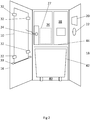
- Fig 1 illustrates an RVM 1.
- the user inserts a large container in exchange for tokens/currency or other benefits.
- the user may need to be provided with detailed feedback and other instructions to ensure correct operation, since different RVMs may operate different criteria for what kinds of containers or states of containers are accepted.
- the RVM 1 comprises a receiving means 22 for receiving containers (container receiver).
- the receiving means 22 is configured to enable insertion of a container into the reverse vending machine 1.
- the illustrated receiving means 22 comprises an aperture through which containers are insertable.
- the dimensions of the aperture depend on the type of containers to be recycled/received.
- the minimum diameter of the aperture may be from the range approximately 6 to approximately 20 centimetres.
- the aperture may be circular as shown, or a different shape. The aperture is shown uncovered but a door could be provided for reducing smell or preventing misuse.
- the in-feed system may comprise one or more of (in order from insertion of a container): a conveyor; a sensor(s) such as a weight sensor 21 and/or photoelectric sensor and/or barcode scanner and/or beam sensor (for knowing where to stop the container for barcode scanning); rollers for rotating containers until the barcode has been scanned; a chute; and a compactor leading to a storage compartment 40 (e.g. Fig 2 ).
- the in-feed system may comprise relevant actuators controlled by a control system 27.
- the conveyor may be two-way to enable automatic return of any automatically rejected containers.
- the RVM 1 comprises a chassis 2.
- the RVM 1 comprises doors 3 comprising a first door 16 and a second door 18.
- the doors 3 facilitate easy access for emptying of containers.
- the doors 3 may be connected to the chassis 2 via hinges (not shown). In other examples, one door or more doors could be provided. Alternatively, at the cost of inconvenience, no doors could be provided and body panels could be removable.
- the first door 16 and the second door 18 are on a same face of the RVM 1, although they could be on different faces.
- the receiving means 22 is located at the second door 18 so that a container in-feed system can be reached easily for maintenance. In other examples, the receiving means 22 could be located elsewhere.
- the illustrated first door 16 is wider than the second door 18 to facilitate the desired display sizes described later, although in other examples the doors 3 could have equal widths.
- the use of two doors enables the RVM 1 to be placed in a narrower corridor for a given RVM 1 width, than an RVM with one wide door, due to the reduced door swing path.
- the RVM 1 is also less likely to topple forward due to increased bending moment from the added weight of the electronic displays described below.
- the chance of toppling can be further reduced by providing adjustable levellers such as the leveller feet 30 shown in Fig 1 .
- the levellers may enable levelling of the RVM 1 to ensure the doors do not swing outwards under gravity when unlocked.
- the leveller feet 30 of Fig 1 may screw in and screw out to enable levelling adjustment.
- Fig 1 also shows that the RVM 1 may comprise wheels (e.g. casters 28) that are not in ground contact when the levellers 30 are in-use.
- a wheel/caster may optionally be provided at the first door 16 and/or at the second door 18 to reduce toppling forces, by directing weight force of the door to the ground without the weight force passing through the chassis 2.
- the first door 16 may comprise a hinged connection to the chassis 2 and the second door 18 may comprise a second hinged connection to the chassis 2. This reduces toppling forces.
- the first door 16 may swing outwardly and parallel to the ground, and the second door 18 may swing outwardly and parallel to the ground.
- the first and second doors 16, 18 may be openable independently of each other.
- one of the doors may comprise a hinged connection to the other of the doors without being connected to the chassis 2.
- the illustrated doors have substantially equal heights, although they could have different heights.
- the doors have heights at least sufficient to enable access to the internal storage compartment 40 shown in Fig 2 , for emptying containers from the RVM 1. In the illustration, the doors are higher to enable access to a plurality of compartments.
- Fig 2 shows a plurality of internal compartments comprising a lower compartment 40, and upper compartment(s) 36, 38.
- the lower compartment comprises the storage compartment 40, to enable containers to be gravity fed.
- Two upper compartments 36, 38 are shown.
- One of the upper compartments may contain maintenance equipment such as liners and cleaning equipment.
- the other of the upper compartments may contain electronics (e.g. the control system 27, actuator(s)). The order, size and number of the compartments may be changed in other implementations.
- the illustrated storage compartment 40 comprises a basket 42 for containers.
- the basket 42 may comprise wheels (e.g. casters) or sliders to function as a trolley, which is easy to remove.
- the basket 42 comprises upstanding walls to reduce splashing and to allow liners such as bin liners to be attached to the basket 42 to line the inside of the basket 42.
- the storage compartment 40 may comprise no basket and users may need to manually remove containers.
- the RVM 1 comprises a plurality of electronic displays.
- the RVM 1 comprises at least a first electronic display 10 and a second electronic display 20.
- the electronic displays may use liquid crystal display technology, light emitting diode technology, or an alternative.
- first electronic display 10 and the second electronic display 20 are located at the doors. In the illustration, but not necessarily in all examples, the first electronic display 10 and the second electronic display 20 are located at different ones of the doors.
- the first electronic display 10 is located at (e.g. attached to) the first door 16.
- the second electronic display 20 is located at (e.g. attached to) the second door 18.
- the first electronic display 10 as described in various examples may be large.
- the first electronic display 10 may therefore be attached to the first door 16 rather than attached to the chassis 2, to improve access to an internal compartment(s) (e.g. upper compartment 36) as described herein by moving the first electronic display 10 out of the way when the first door 16 is opened.
- an internal compartment(s) e.g. upper compartment 36
- the first electronic display 10 and the second electronic display 20 are controlled by a control system 27.
- the control system 27 is configured to present first content on the first electronic display 10 and second different content on the second electronic display 20.
- the second electronic display 20 may be configured to present dynamic content. While the RVM 1 is in-use, the dynamic content may comprise instructional content dynamically responsive to a user's operation of the RVM 1.
- Example instructional second content may direct a user to select a type of container (e.g. plastic or metal). The selection may be made via the second electronic display 20 if the display is a touchscreen, or via separate human-machine interface.
- a type of container e.g. plastic or metal
- Example instructional second content may direct a user to select whether the machine will issue the user with an object such as coins or a ticket such as a voucher. If the user asks for the object to be issued, the control system 27 may control an object issuing device 26 to issue an object to the user.
- the object issuing device 26 comprises a printer, the slot of which is visible. The printer may print a ticket such as a voucher/token/receipt on a medium such as paper/receipt paper.
- a record of the transaction may be stored in a first ledger.
- Example instructional second content may provide the user with a selectable option to cause the machine to store a record of the transaction in a second different ledger such as a charitable donation ledger.
- the option may also cause the RVM 1 to not issue the object. This reduces material/energy consumption.
- Example instructional second content provide the user with a selectable option to end a session, and/or an option to continue the session.
- the object/ticket may be issued with a value dependent on a counter value, the counter value incrementing based on the number of containers accepted.
- the transaction may be written to the ledger indicating the counter value.
- the counter may be reset.
- the RVM 1 may also comprise a separate human machine interface (e.g. button 24) to end the session and issue an object/ticket.
- Example instructional second content may provide a warning when excessive human body intrusion into a container insertion space is detected by one or more sensors such as photoelectric sensors.
- Example instructional second content may provide feedback when a container is rejected, for example as detected by a sensor. If the sensor detects liquid (e.g. weight sensor 21) or an incorrect material such as glass (e.g. also weight sensor 21), feedback may be provided explaining why the container is rejected and directing the user to insert a compliant container.
- compliant containers in an implementation include plastic containers and/or cans. Cans are generally made of lightweight aluminium.
- the second electronic display 20 may further enable access to administrator functions such as viewing the ledger(s) and changing settings.
- the first electronic display 10 presents different content (first content) when in use.
- the first content may be dynamic content such as videos or changing or animated text/images.
- the first content on the first electronic display 10 may be displayed concurrently to the second content on the second electronic display 20.
- the first content for the first electronic display 10 may comprise instructional content that is not dynamically responsive to a user's operation of the RVM 1, even while a user is operating the RVM 1.
- the instructional first content may identify information such as principles of use of the RVM 1, or benefits of using the RVM 1.
- the first content may also comprise custom-content or administrator-specified content, or a combination thereof.
- the first content may dynamically switch between the different types of content at pre-determined time intervals or responsive to some other trigger.
- the first electronic display 10 may comprise a touchscreen to enable user interaction with content such as the first dynamic content.
- the first electronic display 10 may comprise a larger diagonal screen size to ensure that its content can be read from further away.
- the first electronic display 10 and control system 27 may be configured to present larger letter height/icons on the first electronic display 10 than on the second electronic display 20.
- the content may be too large for a user to comfortably see close-up.
- the first electronic display 10 may comprise 200% or more of the display area of the second electronic display 20.
- the first electronic display 10 may comprise 200% or more of the diagonal screen size of the second electronic display 20.
- the first electronic display 10 may have a diagonal screen size of more than 70 centimetres.
- the first electronic display 10 may have a diagonal screen size of more than 100 centimetres to reach a greater audience.
- the first electronic display 10 has a diagonal screen size of 120-130 centimetres (approx. 49 inches).
- the second electronic display 20 may have a diagonal screen size of less than 70 centimetres. To improve packaging on the second door 18, the second electronic display 20 may have a diagonal screen size of less than 50 centimetres.
- the second electronic display has a diagonal screen size of 20-30 centimetres (approx. 10 inches). Based on the specific examples, the first electronic display 10 has a diagonal screen size more than 400% that of the second electronic display 20, in this instance just under/close to 500%.
- the orientation of the first electronic display 10 may be different from the orientation of the second electronic display 20. As shown in Fig 1 , the first electronic display 10 may be oriented in a portrait orientation, and the second electronic display 20 may be oriented in a landscape orientation.
- the above separation of the electronic displays helps the user to spot and focus on RVM-specific instructions via the second electronic display 20 while the first electronic display 10 broadcasts relevant information to queuing or passing individuals.
- the positioning of the displays may reflect the different types of content to be presented.
- the second electronic display 20 may be located closer to the focus of the user's attention, which is likely to be the receiving means 22.
- a nearest edge (bottom edge) of the second electronic display 20 to the receiving means 22 is closer than a nearest edge (right edge) of the first electronic display 10 to the receiving means 22 (e.g. left-most point on the aperture).
- Less eye deviation to the second electronic display 20 is required, therefore the user is physiologically more likely to notice the dynamic instructional content on the second electronic display 20 in their peripheral vision, before they place an object into the receiving means 22 with the mistaken assumption that the container will always be accepted.
- the user is physiologically less likely to mistakenly look at the first electronic display 10, and make any incorrect assumptions based on the absence of use-specific feedback on the first electronic display 10.
- Fig 1 also shows the second electronic display 20 may be vertically offset from the receiving means 22 and not laterally offset from the receiving means 22.
- Fig 1 shows that the second electronic display 20 and the receiving means 22 may be on the same door.
- Fig 1 shows that the first electronic display 10 may be laterally offset from the second electronic display 20 and laterally offset from the receiving means 22.
- Fig 1 shows that the first electronic display 10 may be on a different door.
- the way in which electronic displays may be attached/mounted in a convenient manner is described below and shown in Fig 2 .
- the first electronic display 10 is assumed to be mounted to the first door 16 as the mounting location.
- the first door 16 may comprise an aperture for receiving the first electronic display 10.
- the aperture may be covered by a protective layer (not shown) of at least partially transparent material such as glass or a transparent polymer, to protect a screen of the first electronic display 10 from user damage.
- the first electronic display 10 may be held with respect to the aperture by a display holder.
- the display holder may be part of the first door 16.
- the display holder may be in the interior-facing (non-user facing) side of the first door 16, so that the first door 16 will have to be opened in order to directly access the first electronic display 10.
- Fig 2 shows an example of a display holder.
- the display holder of Fig 2 comprises a peripheral support 33 configured to support the first electronic display 10 at a periphery (e.g. outermost edge) of the first electronic display 10 and resist translation of the first electronic display 10 in at least one direction parallel to the plane of the first door 16.
- Fig 2 shows a peripheral support 33 comprising a lower peripheral support 33 onto which a lower peripheral edge of the first electronic display 10 (in portrait mode) is placed (e.g. rested and/or held by friction).
- the lower peripheral support 33 holds the first electronic display 10 against gravity.
- Side and upper peripheral supports may be provided in other examples, which may at least partially define a cavity into which the first electronic display 10 is insertable.
- the peripheral supports may be surfaces facing into the cavity, and at least some of those surfaces may be surfaces of structural members (rows/columns) of the first door 16 (carrying the weight of the door 16).
- the peripheral support may not inhibit movement of the first electronic display 10 away from the first door 16.
- the lower peripheral support 33 of Fig 2 comprises an optional lip to resist slippage of the first electronic display 10 off the lower peripheral support 33.
- the lower peripheral support 33 may therefore be trough shaped.
- the display holder of Fig 2 comprises retainers 32 configured to resist movement of the first electronic display 10 away from the first door 16.
- the retainers 32 and the peripheral support 33 may together provide no degrees of freedom of movement of the first electronic display 10.
- the retainers 32 may provide an interference that prohibits pulling of the display away from the first door 16 in an axis perpendicular to the plane of the first door 16.
- the retainers 32 comprise plates.
- the plates may extend a few centimetres (e.g. less than 20cm) past the peripheries of the first electronic display 10.
- Fig 2 shows an upper retainer(s) 32 and a lower retainer(s) 32.
- the upper retainer may resist tipping of the first electronic display 10, and one or more of the retainers 32 may be adjustable to bias the first electronic display 10 towards a bearing surface of the first door 16, to stop the first electronic display 10 from vibrating or moving excessively in use, or sliding away from the peripheral support 33.
- One or more of the retainers 32 may be adjustable in different ways such as accommodating different thicknesses of electronic displays (e.g. vary by how much the plate is screwed down), and/or varying an amount of interference between a retainer and a portion of the first electronic display 10 (e.g. vary angle of the plate). This means that if the first electronic display 10 is replaced or redesigned, the display holder provides a degree of universal fit in at least some dimensions.
- the first electronic display 10 could be removable by first unscrewing the retainers 32, e.g. from the first door 16.
- first electronic display 10 may not need to be modified (e.g. drilled).
- the retainers 32 may be attached to the first door 16, and not attached to the first electronic display 10. Or, if the retainers 32 are attached by glue or other means, the retainers 32 are not configured to be attached at any specific location of the first electronic display 10.
- the second electronic display 20 may be mounted to the second door 18 via the same or other means.
- the second electronic display 20 could be mounted to a frame, and the frame could be reversibly/irrevocably mounted to an interior-facing surface of the second door 18 such as a sheet metal/material surface.
- the frame may be non-load bearing.
- the frame could provide the function of the peripheral support. Retainers could be provided in the form of lips and/or plates.
- the large size of the first electronic display 10 presents a challenge in the environment of the RVM 1 where liquid splashes need to be contained.
- the bottom edge (closest to ground) of the display (in portrait) may extend lower than the top edge of the storage compartment 40.
- the top edge of the storage compartment 40 may be an upper surface of the storage compartment 40.
- the upper surface of the storage compartment 40 may be the underside of an interior shelf 44 of the RVM 1 separating upper and lower compartments.
- the interior shelf 44 helps to ensure the upper part of the first electronic display 10 is in a less humid environment protected from splashes.
- the part of the first electronic display 10 which protrudes into the storage compartment 40 may be protected in other ways.
- the basket 42/trolley as described earlier may have upstanding walls that may extend to within a close proximity (e.g. approximately 10cm or less) of the top edge of the storage compartment 40. This minimises the gap for liquid splashes.
- the in-feed system may comprise a sensor configured to provide a parameter dependent on a presence of liquid in a container.
- a weight sensor 21 may provide a weight parameter which depends on the presence of liquid, or other sensors may be employed.
- the weight sensor 21 may compare the weight of at least a portion of the in-feed system before and after insertion of the container. Insertion of the container may be detected by a photoelectric/beam sensor or the like.
- the control system 27 is configured to output a rejection command in dependence on the parameter indicating (probable) liquid in the container (e.g. above-threshold weight).
- the rejection command may cause a reverse conveyor to return the item and/or may cause the second electronic display 20 to provide feedback that the container is rejected.
- the same weight parameter may also depend on the material of the container, so that glass containers may be rejected.
- cable grommets 34 such as rubber grommets for apertures in the chassis where electrical cables pass towards the electronic display(s).
- the grommets may provide splash resistance and resistance to air ingress.
- the electrical cables for visual display content, power, etc, may pass through the upper compartments and avoid the lower compartments.
- Fig 3 illustrates a schematic for the control system 27.
- the control system 27 comprises at least one controller 302 or other computer apparatus.
- the control system 27 comprises separate controllers for the separate electronic displays.
- the controller 302 and control system 27 comprises: at least one processor 304; and at least one memory 306 electrically coupled to the processor and having instructions 308 (e.g. a computer program) stored therein that, when executed, cause one or more of the control system functions described herein to be performed.
- instructions 308 e.g. a computer program
Landscapes
- Physics & Mathematics (AREA)
- General Physics & Mathematics (AREA)
- Control Of Vending Devices And Auxiliary Devices For Vending Devices (AREA)
Priority Applications (1)
| Application Number | Priority Date | Filing Date | Title |
|---|---|---|---|
| EP19185510.5A EP3764329A1 (de) | 2019-07-10 | 2019-07-10 | Rücknahmeautomat |
Applications Claiming Priority (1)
| Application Number | Priority Date | Filing Date | Title |
|---|---|---|---|
| EP19185510.5A EP3764329A1 (de) | 2019-07-10 | 2019-07-10 | Rücknahmeautomat |
Publications (1)
| Publication Number | Publication Date |
|---|---|
| EP3764329A1 true EP3764329A1 (de) | 2021-01-13 |
Family
ID=67253688
Family Applications (1)
| Application Number | Title | Priority Date | Filing Date |
|---|---|---|---|
| EP19185510.5A Withdrawn EP3764329A1 (de) | 2019-07-10 | 2019-07-10 | Rücknahmeautomat |
Country Status (1)
| Country | Link |
|---|---|
| EP (1) | EP3764329A1 (de) |
Citations (4)
| Publication number | Priority date | Publication date | Assignee | Title |
|---|---|---|---|---|
| US5624018A (en) * | 1995-11-28 | 1997-04-29 | Schuff; David A. | Aluminum can recycling and coupon dispenser apparatus |
| EP1968022A2 (de) * | 2007-03-09 | 2008-09-10 | Sielaff Gmbh & Co. Kg Automatenbau | Verkaufsautomat und Verfahren |
| US20160027231A1 (en) * | 2013-03-12 | 2016-01-28 | Intercontinental Great Brands Llc | Display-based vending apparatus and method |
| US20170256115A1 (en) * | 2016-03-02 | 2017-09-07 | Manufacturing Resources International, Inc. | Vending machine having a transparent display |
-
2019
- 2019-07-10 EP EP19185510.5A patent/EP3764329A1/de not_active Withdrawn
Patent Citations (4)
| Publication number | Priority date | Publication date | Assignee | Title |
|---|---|---|---|---|
| US5624018A (en) * | 1995-11-28 | 1997-04-29 | Schuff; David A. | Aluminum can recycling and coupon dispenser apparatus |
| EP1968022A2 (de) * | 2007-03-09 | 2008-09-10 | Sielaff Gmbh & Co. Kg Automatenbau | Verkaufsautomat und Verfahren |
| US20160027231A1 (en) * | 2013-03-12 | 2016-01-28 | Intercontinental Great Brands Llc | Display-based vending apparatus and method |
| US20170256115A1 (en) * | 2016-03-02 | 2017-09-07 | Manufacturing Resources International, Inc. | Vending machine having a transparent display |
Similar Documents
| Publication | Publication Date | Title |
|---|---|---|
| TW517215B (en) | An automatic card dispensing unit with display capability | |
| EP1947614A1 (de) | Förderbandmittel für zurücksendbare Elemente | |
| CA2680875A1 (en) | Automated banking machine which dispenses, receives and stores notes and other financial instrument sheets | |
| EP0643374B1 (de) | Elektronisches Frankiersystem mit einer mechanischen Einrichtung zur Handhabung von Poststücken | |
| CN112141557B (zh) | 回收装置 | |
| KR102137790B1 (ko) | 카트리지 공급장치를 이용한 카드전용 키오스크 판매기 | |
| EP3764329A1 (de) | Rücknahmeautomat | |
| JP2018131288A (ja) | 物品回収装置 | |
| US6938896B2 (en) | Automatic card dispensing unit with display capability | |
| JP2023174906A (ja) | 物品回収装置 | |
| JP2020055006A (ja) | 物品回収装置 | |
| JP7423105B2 (ja) | ペットボトル減容装置 | |
| US20220225802A1 (en) | Contactless Condiment Dispenser | |
| CN206711245U (zh) | 一种面膜自动售卖机 | |
| KR102525991B1 (ko) | 멀티자동판매기의 상품 배출장치 | |
| CA1319388C (en) | Cash register hood | |
| JP7348630B2 (ja) | 物品回収装置 | |
| CN110550369B (zh) | 仓储配货设备及仓储配货系统 | |
| JP7502829B2 (ja) | 容器回収装置 | |
| JP7555618B2 (ja) | 減容装置 | |
| JP2022020251A (ja) | 容器減容装置 | |
| CN221668339U (zh) | 取货箱及自动售货机 | |
| JP2023119073A (ja) | 物品回収装置 | |
| CN218241005U (zh) | 一种片状卫生巾出货装置及出货箱 | |
| RU2748644C1 (ru) | Передняя лицевая панель автомата для продажи питьевой воды |
Legal Events
| Date | Code | Title | Description |
|---|---|---|---|
| PUAI | Public reference made under article 153(3) epc to a published international application that has entered the european phase |
Free format text: ORIGINAL CODE: 0009012 |
|
| STAA | Information on the status of an ep patent application or granted ep patent |
Free format text: STATUS: THE APPLICATION HAS BEEN PUBLISHED |
|
| AK | Designated contracting states |
Kind code of ref document: A1 Designated state(s): AL AT BE BG CH CY CZ DE DK EE ES FI FR GB GR HR HU IE IS IT LI LT LU LV MC MK MT NL NO PL PT RO RS SE SI SK SM TR |
|
| AX | Request for extension of the european patent |
Extension state: BA ME |
|
| STAA | Information on the status of an ep patent application or granted ep patent |
Free format text: STATUS: THE APPLICATION IS DEEMED TO BE WITHDRAWN |
|
| 18D | Application deemed to be withdrawn |
Effective date: 20210714 |