EP3764426A1 - Séparateur ayant une adhérence d'électrode et une propriété de résistance améliorées, pour batterie secondaire au lithium, et batterie secondaire au lithium comprenant ce séparateur - Google Patents
Séparateur ayant une adhérence d'électrode et une propriété de résistance améliorées, pour batterie secondaire au lithium, et batterie secondaire au lithium comprenant ce séparateur Download PDFInfo
- Publication number
- EP3764426A1 EP3764426A1 EP19866774.3A EP19866774A EP3764426A1 EP 3764426 A1 EP3764426 A1 EP 3764426A1 EP 19866774 A EP19866774 A EP 19866774A EP 3764426 A1 EP3764426 A1 EP 3764426A1
- Authority
- EP
- European Patent Office
- Prior art keywords
- separator
- weight
- coating layer
- secondary battery
- lithium secondary
- Prior art date
- Legal status (The legal status is an assumption and is not a legal conclusion. Google has not performed a legal analysis and makes no representation as to the accuracy of the status listed.)
- Granted
Links
Images






Classifications
-
- H—ELECTRICITY
- H01—ELECTRIC ELEMENTS
- H01M—PROCESSES OR MEANS, e.g. BATTERIES, FOR THE DIRECT CONVERSION OF CHEMICAL ENERGY INTO ELECTRICAL ENERGY
- H01M50/00—Constructional details or processes of manufacture of the non-active parts of electrochemical cells other than fuel cells, e.g. hybrid cells
- H01M50/40—Separators; Membranes; Diaphragms; Spacing elements inside cells
- H01M50/489—Separators, membranes, diaphragms or spacing elements inside the cells, characterised by their physical properties, e.g. swelling degree, hydrophilicity or shut down properties
-
- H—ELECTRICITY
- H01—ELECTRIC ELEMENTS
- H01M—PROCESSES OR MEANS, e.g. BATTERIES, FOR THE DIRECT CONVERSION OF CHEMICAL ENERGY INTO ELECTRICAL ENERGY
- H01M50/00—Constructional details or processes of manufacture of the non-active parts of electrochemical cells other than fuel cells, e.g. hybrid cells
- H01M50/40—Separators; Membranes; Diaphragms; Spacing elements inside cells
- H01M50/409—Separators, membranes or diaphragms characterised by the material
- H01M50/411—Organic material
- H01M50/414—Synthetic resins, e.g. thermoplastics or thermosetting resins
- H01M50/426—Fluorocarbon polymers
-
- H—ELECTRICITY
- H01—ELECTRIC ELEMENTS
- H01M—PROCESSES OR MEANS, e.g. BATTERIES, FOR THE DIRECT CONVERSION OF CHEMICAL ENERGY INTO ELECTRICAL ENERGY
- H01M10/00—Secondary cells; Manufacture thereof
- H01M10/05—Accumulators with non-aqueous electrolyte
- H01M10/052—Li-accumulators
-
- H—ELECTRICITY
- H01—ELECTRIC ELEMENTS
- H01M—PROCESSES OR MEANS, e.g. BATTERIES, FOR THE DIRECT CONVERSION OF CHEMICAL ENERGY INTO ELECTRICAL ENERGY
- H01M50/00—Constructional details or processes of manufacture of the non-active parts of electrochemical cells other than fuel cells, e.g. hybrid cells
- H01M50/40—Separators; Membranes; Diaphragms; Spacing elements inside cells
- H01M50/409—Separators, membranes or diaphragms characterised by the material
- H01M50/411—Organic material
- H01M50/414—Synthetic resins, e.g. thermoplastics or thermosetting resins
- H01M50/417—Polyolefins
-
- H—ELECTRICITY
- H01—ELECTRIC ELEMENTS
- H01M—PROCESSES OR MEANS, e.g. BATTERIES, FOR THE DIRECT CONVERSION OF CHEMICAL ENERGY INTO ELECTRICAL ENERGY
- H01M50/00—Constructional details or processes of manufacture of the non-active parts of electrochemical cells other than fuel cells, e.g. hybrid cells
- H01M50/40—Separators; Membranes; Diaphragms; Spacing elements inside cells
- H01M50/409—Separators, membranes or diaphragms characterised by the material
- H01M50/431—Inorganic material
-
- H—ELECTRICITY
- H01—ELECTRIC ELEMENTS
- H01M—PROCESSES OR MEANS, e.g. BATTERIES, FOR THE DIRECT CONVERSION OF CHEMICAL ENERGY INTO ELECTRICAL ENERGY
- H01M50/00—Constructional details or processes of manufacture of the non-active parts of electrochemical cells other than fuel cells, e.g. hybrid cells
- H01M50/40—Separators; Membranes; Diaphragms; Spacing elements inside cells
- H01M50/409—Separators, membranes or diaphragms characterised by the material
- H01M50/443—Particulate material
-
- H—ELECTRICITY
- H01—ELECTRIC ELEMENTS
- H01M—PROCESSES OR MEANS, e.g. BATTERIES, FOR THE DIRECT CONVERSION OF CHEMICAL ENERGY INTO ELECTRICAL ENERGY
- H01M50/00—Constructional details or processes of manufacture of the non-active parts of electrochemical cells other than fuel cells, e.g. hybrid cells
- H01M50/40—Separators; Membranes; Diaphragms; Spacing elements inside cells
- H01M50/409—Separators, membranes or diaphragms characterised by the material
- H01M50/446—Composite material consisting of a mixture of organic and inorganic materials
-
- H—ELECTRICITY
- H01—ELECTRIC ELEMENTS
- H01M—PROCESSES OR MEANS, e.g. BATTERIES, FOR THE DIRECT CONVERSION OF CHEMICAL ENERGY INTO ELECTRICAL ENERGY
- H01M50/00—Constructional details or processes of manufacture of the non-active parts of electrochemical cells other than fuel cells, e.g. hybrid cells
- H01M50/40—Separators; Membranes; Diaphragms; Spacing elements inside cells
- H01M50/409—Separators, membranes or diaphragms characterised by the material
- H01M50/449—Separators, membranes or diaphragms characterised by the material having a layered structure
-
- H—ELECTRICITY
- H01—ELECTRIC ELEMENTS
- H01M—PROCESSES OR MEANS, e.g. BATTERIES, FOR THE DIRECT CONVERSION OF CHEMICAL ENERGY INTO ELECTRICAL ENERGY
- H01M50/00—Constructional details or processes of manufacture of the non-active parts of electrochemical cells other than fuel cells, e.g. hybrid cells
- H01M50/40—Separators; Membranes; Diaphragms; Spacing elements inside cells
- H01M50/409—Separators, membranes or diaphragms characterised by the material
- H01M50/449—Separators, membranes or diaphragms characterised by the material having a layered structure
- H01M50/457—Separators, membranes or diaphragms characterised by the material having a layered structure comprising three or more layers
-
- H—ELECTRICITY
- H01—ELECTRIC ELEMENTS
- H01M—PROCESSES OR MEANS, e.g. BATTERIES, FOR THE DIRECT CONVERSION OF CHEMICAL ENERGY INTO ELECTRICAL ENERGY
- H01M50/00—Constructional details or processes of manufacture of the non-active parts of electrochemical cells other than fuel cells, e.g. hybrid cells
- H01M50/40—Separators; Membranes; Diaphragms; Spacing elements inside cells
- H01M50/463—Separators, membranes or diaphragms characterised by their shape
-
- H—ELECTRICITY
- H01—ELECTRIC ELEMENTS
- H01M—PROCESSES OR MEANS, e.g. BATTERIES, FOR THE DIRECT CONVERSION OF CHEMICAL ENERGY INTO ELECTRICAL ENERGY
- H01M50/00—Constructional details or processes of manufacture of the non-active parts of electrochemical cells other than fuel cells, e.g. hybrid cells
- H01M50/40—Separators; Membranes; Diaphragms; Spacing elements inside cells
- H01M50/489—Separators, membranes, diaphragms or spacing elements inside the cells, characterised by their physical properties, e.g. swelling degree, hydrophilicity or shut down properties
- H01M50/491—Porosity
-
- Y—GENERAL TAGGING OF NEW TECHNOLOGICAL DEVELOPMENTS; GENERAL TAGGING OF CROSS-SECTIONAL TECHNOLOGIES SPANNING OVER SEVERAL SECTIONS OF THE IPC; TECHNICAL SUBJECTS COVERED BY FORMER USPC CROSS-REFERENCE ART COLLECTIONS [XRACs] AND DIGESTS
- Y02—TECHNOLOGIES OR APPLICATIONS FOR MITIGATION OR ADAPTATION AGAINST CLIMATE CHANGE
- Y02E—REDUCTION OF GREENHOUSE GAS [GHG] EMISSIONS, RELATED TO ENERGY GENERATION, TRANSMISSION OR DISTRIBUTION
- Y02E60/00—Enabling technologies; Technologies with a potential or indirect contribution to GHG emissions mitigation
- Y02E60/10—Energy storage using batteries
Definitions
- the present disclosure relates to a separator for a lithium secondary battery with improved adhesiveness towards electrode and resistance characteristics and a lithium secondary battery comprising the separator.
- a lithium secondary battery is a rechargeable energy storage device with high energy density that reversibly converts chemical energy into electrical energy, basically including a positive electrode, a negative electrode, a separator and an electrolyte solution, and has a wide range of application in small electronic devices such as mobile phones and laptop computers.
- HEVs hybrid electric vehicles
- Plug-in EVs Plug-in EVs
- e-bikes energy storage systems
- ESSs energy storage systems
- the separator commonly used in the lithium secondary battery show severe thermal contraction behaviors in a high temperature due to its material properties and manufacturing process characteristics, causing a stability problem, for example, an internal short.
- an organic-inorganic composite porous separator having a porous inorganic coating layer formed by coating a mixture of inorganic particles and binder polymer on a porous substrate has been suggested.
- an electrode assembly is formed by stacking an electrode and the separator, there is a high risk that the electrode and the separator may be separated due to insufficient interlayer adhesiveness, and in this case, the separated inorganic particles may act as local defects in the device.
- the PVDF-based copolymer changes in solubility in solvent, electrolyte solution wetting property and adhesiveness towards electrode according to the type and content of comonomer.
- HFP and CTFE comonomers when HFP and CTFE comonomers are used, they provide amorphous regions and provide solubility in solvent, electrolyte solution wetting property and adhesiveness towards electrode.
- amorphous regions increase and solubility in solvent and electrolyte solution wetting property increase, while the phase transition characteristics for non-solvent are poor, making it difficult to form a pore structure by wetting.
- the adhesiveness and phase transition characteristics of the binder polymer change according to the type of comonomer.
- PVDF-CTFE forms a micropore structure with a wider surface area and has higher adhesiveness than PVDF-HFP in the same coating condition.
- it is sensitive to non-solvents, making it difficult to control the pore shape and it has low solubility in solvent, making it difficult to manage the process.
- two types of PVDF-based copolymers may be used in combination so that advantages of two types of binder polymers work together.
- the process complexity increases and the phase separation rates of the two types of binder polymers are different, resulting in the pore structure and distribution of the binder polymers non-uniform, thereby failing to obtain a targeted binder polymer effect.
- the present disclosure is directed to providing a separator for a lithium secondary battery having a porous coating layer including inorganic particles, in which the separator has improved adhesiveness towards electrode and resistance characteristics.
- the present disclosure is further directed to providing a separator for a lithium secondary battery having a porous coating layer including inorganic particles, in which the separator has improved adhesiveness towards electrode and reduced interfacial resistance characteristics.
- the present disclosure is further directed to providing a separator for a lithium secondary battery having a porous coating layer including inorganic particles, in which the separator has improved adhesiveness towards electrode, reduced interfacial resistance characteristics and improved air permeability, and besides, improved thermal stability due to interstitial volumes present in the porous coating layer.
- a separator for a lithium secondary battery comprising a porous substrate, and a porous coating layer disposed on at least one surface of the porous substrate and comprising inorganic particles and binder polymer
- the binder polymer is terpolymer including a repeat unit derived from vinylidenefluoride (VDF), a repeat unit derived from hexafluoropropylene (HFP) and a repeat unit derived from chlorotrifluoroethylene (CTFE)
- the terpolymer includes 65 to 90 weight% of the repeat unit derived from VDF, 1 to 28 weight% of the repeat unit derived from HFP and 5 to 28 weight% of the repeat unit derived from CTFE
- the separator for a lithium secondary battery has adhesiveness towards electrode ranging from 30 gf/25mm to 150 gf/25mm and machine direction (MD) thermal shrinkage of 1 to 18% and transverse direction (TD) thermal shrinkage of 1 to 17%.
- the separator for a lithium secondary battery as defined in the first embodiment, wherein the terpolymer includes 65 to 90 weight% of the repeat unit derived from vinylidenefluoride (VDF), 1 to 20 weight% of the repeat unit derived from hexafluoropropylene (HFP) and 7 to 28 weight% of the repeat unit derived from chlorotrifluoroethylene (CTFE).
- VDF vinylidenefluoride
- HFP hexafluoropropylene
- CTFE chlorotrifluoroethylene
- the separator for a lithium secondary battery as defined in the first or second embodiment, wherein the terpolymer includes 70 to 85 weight% of the repeat unit derived from vinylidenefluoride (VDF), 1 to 5 weight% of the repeat unit derived from hexafluoropropylene (HFP) and 7 to 28 weight% of the repeat unit derived from chlorotrifluoroethylene (CTFE).
- VDF vinylidenefluoride
- HFP hexafluoropropylene
- CTFE chlorotrifluoroethylene
- the separator for a lithium secondary battery as defined in any one of the first to third embodiments, wherein the terpolymer has a weight average molecular weight of 200,000 to 1,000,000.
- the separator for a lithium secondary battery as defined in any one of the first to fourth embodiments, wherein the porous coating layer comprises interstitial volumes between the inorganic particles, the interstitial volumes being voids defined by substantial contact between adjacent inorganic particles.
- the separator for a lithium secondary battery as defined in any one of the first to fifth embodiments, wherein a weight fraction of F (fluorine) and a weight fraction of Cl (chlorine) are indicated such that a sum of each weight fraction is 100, the weight fraction (a) of Cl (chlorine) in a surface region of the porous coating layer and the weight fraction (b) of Cl (chlorine) in a bottom region of the porous coating layer satisfy the following condition, wherein the surface region is defined as a region extending downwards from the surface to the bottom by 10% of the total thickness of the porous coating layer, and the bottom region is defined as a region extending upwards from the bottom of the porous coating layer to the surface by 10% of the total thickness of the porous coating layer: 0 ⁇ a ⁇ b / a ⁇ 100 ⁇ 100 .
- the separator for a lithium secondary battery as defined in any one of the first to sixth embodiments, wherein when a weight fraction of F (fluorine) and a weight fraction of Cl (chlorine) are indicated such that a sum of each weight fraction is 100, the weight fraction (a) of Cl (chlorine) in the surface region of the porous coating layer and the weight fraction (b) of Cl (chlorine) in the bottom region of the porous coating layer satisfy the following condition, wherein the surface region is defined as a region extending downwards from the surface to the bottom by 10% of the total thickness of the porous coating layer, and the bottom region is defined as a region extending upwards from the bottom of the porous coating layer to the surface by 10% of the total thickness of the porous coating layer: 0 ⁇ a ⁇ b / a ⁇ 100 ⁇ 50 .
- the separator for a lithium secondary battery as defined in any one of the first to seventh embodiments, wherein the porous coating layer further comprises an additional binder polymer, a dispersant, or a combination thereof.
- the separator for a lithium secondary battery as defined in any one of the first to eighth embodiments, wherein the additional binder polymer is one selected from the group consisting of vinylidenefluoride derived binary copolymer, polymethylmethacrylate, polyacrylonitrile, polyvinylpyrrolidone, polyvinylacetate, polyethylene-co-vinyl acetate, polyethylene oxide, cellulose acetate, cellulose acetate butyrate, cellulose acetate propionate, cyanoethylpullulan, cyanoethylpolyvinylalcohol, cyanoethylcellulose, cyanoethylsucrose, pullulan, carboxyl methyl cellulose, acrylonitrile-styrene-butadiene copolymer and polyimide, or a combination thereof.
- the additional binder polymer is one selected from the group consisting of vinylidenefluoride derived binary copolymer, polymethylmethacrylate,
- the separator for a lithium secondary battery as defined in the first embodiment, wherein the separator for a lithium secondary battery has 1.3 to 7.0 times higher air permeability than that of the porous substrate.
- a lithium secondary battery comprising a positive electrode and a negative electrode and a separator interposed between the positive electrode and the negative electrode, wherein the separator is the separator for a lithium secondary battery according to any one of the first to tenth embodiments.
- the separator for a lithium secondary battery according to the present disclosure has uniform micropores on the surface, and thus has the increased adhesive surface area with electrode and consequential improved adhesiveness towards electrode.
- the separator for a lithium secondary battery according to the present disclosure has ion conduction paths due to the uniform micropores formed on the surface, thereby achieving low interfacial resistance and improved air permeability. Accordingly, a lithium secondary battery using the separator for a lithium secondary battery according to the present disclosure may have improved output and life characteristics.
- a separator comprising a porous substrate; and a porous coating layer disposed on at least one surface of the porous substrate and comprising inorganic particles and binder polymer, wherein the binder polymer is terpolymer including a repeat unit derived from vinylidenefluoride (VDF), a repeat unit derived from hexafluoropropylene (HFP) and a repeat unit derived from chlorotrifluoroethylene (CTFE).
- VDF vinylidenefluoride
- HFP hexafluoropropylene
- CTFE chlorotrifluoroethylene
- the porous substrate may include, without limitation, any type that is commonly used as a separator material for a lithium secondary battery if it electrically insulates the negative electrode from the positive electrode to prevent a short circuit and provides a movement path of lithium ions.
- the porous substrate includes, but is not limited thereto, for example, a porous substrate made of at least one of polymer resins such as polyolefin, polyethyleneterephthalate, polybutyleneterephthalate, polyacetal, polyamide, polycarbonate, polyimide, polyetheretherketone, polyethersulfone, polyphenyleneoxide, polyphenylenesulfide and polyethylenenaphthalene.
- the porous substrate a film in the shape of a sheet formed by melting polymer resin may be used.
- the porous substrate is a porous polymer substrate which is a film in the shape of a sheet formed by melting the polymer resin.
- porous polymer substrate is one of the following:
- the thickness of the porous substrate may be appropriately selected within the range of between 5 and 50 ⁇ m.
- the range of the porous substrate is not particularly limited to the above-described range, but when the thickness is so much less than the above-described lower limit, the separator is prone to damage while the battery is being used due to the degradation of the mechanical properties.
- the size and porosity of the pores present in the porous substrate are not particularly limited, but the pore size and porosity may be 0.01 to 50 ⁇ m and 10 to 95% respectively.
- the porous coating layer is formed on one or two surfaces of the polymer substrate.
- the porous coating layer comprises a mixture of inorganic particles and binder polymer, and it is formed into a layer in which the inorganic particles are bonded together by the medium of the binder polymer. That is, the inorganic particles in the porous coating layer are coated with the binder polymer on the surface in whole or in part, and hence the inorganic particles are bonded to each other point-to-point and/or surface-to-surface. Additionally, the porous coating layer is adhered to the porous substrate by the medium of the binder polymer.
- the separator of the present disclosure has much improved heat resistance and mechanical properties due to the surface coating of the porous substrate with the porous coating layer including the inorganic particles.
- the binder of the porous coating layer may bind together the inorganic particles to keep them bonded to each other (i.e., the binder connects and immobilizes the inorganic particles), and the binder may keep the inorganic particles bonded to the porous polymer substrate.
- the inorganic particles of the porous coating layer may form interstitial volumes by substantial contact between them, and in this instance, the interstitial volumes refer to voids defined by the inorganic particles in substantial contact with each other in a packed structure (closed packed or densely packed) by the inorganic particles.
- the interstitial volumes between the inorganic particles are voids that will form the pores of the porous coating layer.
- the porous coating layer has a microporous structure by the interstitial volumes between the inorganic particles and also serves as a spacer to maintain the physical shape of the porous coating layer. Additionally, since the inorganic particles generally do not change in physical properties at high temperature of 200°C or above, the formed porous coating layer allows the separator to have good heat resistance, for example, thermal shrinkage.
- the porous coating layer may have the thickness ranging from 1 ⁇ m to 50 ⁇ m, or from 2 ⁇ m to 30 ⁇ m or from 2 ⁇ m to 20 ⁇ m.
- a ratio of the amount of the inorganic particles and the amount of the binder polymer is determined considering the thickness, pore size and porosity of the finally formed porous coating layer of the present disclosure, and the amount of the inorganic particles is 50 to 99.9 weight% or 60 to 99.5 weight%, and the amount of the binder polymer is 0.1 to 50 weight% or 0.5 to 40 weight% on the basis of weight ratio.
- the amount of the inorganic particles is less than 50 weight%, a very large amount of binder polymer reduces the pore size and porosity due to reduction of the interstitial volumes between the inorganic particles, causing the final battery performance degradation.
- the amount of inorganic particles is larger than 99.9 weight%, a very small amount of binder polymer degrades the mechanical properties of the final porous coating layer due to reduction of the bond strength between the inorganic particles.
- the inorganic particle size of the porous coating layer is not limited, but for the coating layer with uniform thickness and appropriate porosity, the inorganic particle size may range from 0.001 to 10 ⁇ m or from 0.01 to 10 ⁇ m or from 0.05 to 5 ⁇ m or from 0.1 to 2 ⁇ m.
- the inorganic particle size satisfies the above-described range, dispersion is maintained, making it easy to adjust the properties of the separator, and an increase in thickness of the porous coating layer is avoided, thereby improving the mechanical properties, and there is a low probability that an internal short may occur during charging and discharging of a battery due to the large pore size.
- the inorganic particles include, without limitation, any type of inorganic particle that is electrochemically stable. That is, the inorganic particles are not limited to a particular type if they do not cause oxidation and/or reduction reactions in the operating voltage range (for example, 0 ⁇ 5V vs Li/Li + ) of an electrochemical device used. Particularly, the use of ion transportable inorganic particles increases the ionic conductivity in the electrochemical device, contributing to the performance improvement. Additionally, the use of inorganic particles of high dielectric constant contributes to the dissociation increase of an electrolyte salt, for example, a lithium salt, in a liquid electrolyte, thereby improving the ionic conductivity of an electrolyte solution.
- an electrolyte salt for example, a lithium salt
- the inorganic particles may include inorganic particles of high dielectric constant of 5 or more or 10 or more, lithium ion transportable inorganic particles, or a combination thereof.
- Non-limiting examples of the inorganic particles having the dielectric constant of 5 or more may include BaTiO 3 , Pb(Zr,Ti)O 3 (PZT), Pb 1-x La x Zr 1-y Ti y O 3 (PLZT, 0 ⁇ x ⁇ 1,0 ⁇ y ⁇ 1), Pb(Mg 1/3 Nb 2/3 )O 3 -PbTiO 3 (PMN-PT), hafnia (HfO 2 ), SrTiO 3 , SnO 2 , CeO 2 , MgO, NiO, CaO, ZnO, ZrO 2 , Y 2 O 3 , Al 2 O 3 , ⁇ -AlOOH, SiC, TiO 2 , etc., alone or in combination. Additionally, the inorganic
- Non-limiting examples of the lithium ion transportable inorganic particles may include lithium phosphate (Li 3 PO 4 ), lithium titanium phosphate (Li x Ti y (PO 4 ) 3 , 0 ⁇ x ⁇ 2, 0 ⁇ y ⁇ 3), lithium aluminum titanium phosphate (Li x Al y Ti z (PO 4 ) 3 , 0 ⁇ x ⁇ 2, 0 ⁇ y ⁇ 1, 0 ⁇ z ⁇ 3), (LiAlTiP) x O y based glass (0 ⁇ x ⁇ 4, 0 ⁇ y ⁇ 13) such as 14Li 2 O-9Al 2 O 3 -38TiO 2 -39P 2 O 5 , etc., lithium lanthanum titanate (Li x La y TiO 3 , 0 ⁇ x ⁇ 2, 0 ⁇ y ⁇ 3), lithium germanium thiophosphate (Li x Ge y P z S w ,
- the binder polymer included in the porous coating layer includes a repeat unit derived from vinylidene fluoride (VDF), a repeat unit derived from hexafluoropropylene (HFP) and a repeat unit derived from chlorotrifluoroethylene (CTFE), and preferably, the binder polymer substantially includes a repeat unit derived from VDF, a repeat unit derived from HFP and a repeat unit derived from CTFE, and more preferably, a repeat unit derived from VDF, a repeat unit derived from HFP and a repeat unit derived from CTFE.
- the term "substantially” represents that although there are unavoidably a very small or trace amount of impurities or other substances in the manufacturing process, the amount of impurities or other substances does not provide a significant effect on the intended object.
- the VDF-HFP-CTFE terpolymer used in the porous coating layer of the present disclosure includes a repeat unit derived from VDF, a repeat unit derived from HFP and a repeat unit derived from CTFE, and when the sum of the derived repeat units is 100 weight%, the VDF-HFP-CTFE terpolymer includes 65 to 90 weight% of repeat units derived from VDF, 1 to 28 weight% of repeat units derived from HFP and 5 to 28 weight% of repeat units derived from CTFE.
- the VDF-HFP-CTFE terpolymer may include 65 to 90 weight% of repeat units derived from VDF, 1 to 20 weight% of repeat units derived from HFP and 7 to 28 weight% of repeat units derived from CTFE. In another particular embodiment of the present disclosure, the VDF-HFP-CTFE terpolymer may include 70 to 90 weight% of repeat units derived from VDF, 1 to 5 weight% of repeat units derived from HFP and 7 to 28 weight% of repeat units derived from CTFE.
- the VDF-HFP-CTFE terpolymer may include 70 to 85 weight% of repeat units derived from VDF, 1 to 5 weight% of repeat units derived from HFP and 7 to 28 weight% of repeat units derived from CTFE. In another particular embodiment of the present disclosure, the VDF-HFP-CTFE terpolymer may include 74 to 80 weight% of repeat units derived from VDF, 1 to 15 weight% of repeat units derived from HFP and 10 to 26 weight% of repeat units derived from CTFE.
- the VDF-HFP-CTFE terpolymer may include 74 to 80 weight% of repeat units derived from VDF, 1 to 10 weight% of repeat units derived from HFP and 10 to 26 weight% of repeat units derived from CTFE.
- the phase separation characteristics are poor, failing to form a binder polymer layer on surface, and when the amount of repeat units derived from VDF is more than the above-described range, crystallinity is high, failing to swell in an electrolyte solution. Additionally, the amount of repeat units derived from HFP is less than the above-described range, the solubility in solvent is low, making it difficult to control the process, and phase separation is fast and the bond strength in the coating layer is low. When the amount of repeat units derived from HFP is more than the above-described range, the solubility in solvent is high, failing to implement the phase separation characteristics.
- the amount of repeat units derived from CTFE is less than the above-described range, the micropore structure formation effect is insufficient, and when the amount of repeat units derived from CTFE is more than the above-described range, the binder polymer swells after an electrolyte solution is injected when manufacturing a cell, causing the separation of the coating layer.
- the VDF-HFP-CTFE terpolymer used in the porous coating layer of the present disclosure may have the sum of the repeating units derived from HFP and the repeating units derived from CTFE ranging from 10 to 35 weight% or from 15 to 30 weight%, when the sum of the derived repeating units is 100 weight%.
- CTFE a solubility in solvent and miscibility in electrolyte solution
- the VDF-HFP-CTFE terpolymer may satisfy the above-described derived repeat unit composition and have the weight average molecular weight of 200,000 to 1,000,000 or 200,000 to 800,000 or 300,000 to 700,000 or 400,000 to 650,000.
- weight average molecular weight satisfies the above-described range, binder polymer migration to a surface layer is easy, and sufficient adhesiveness is provided.
- the VDF-HFP-CTFE terpolymer may be present in an amount of 3 to 100 parts by weight or 3 to 70 parts by weight or 5 to 45 parts by weight or 5 to 35 parts by weight based on 100 parts by weight of the inorganic particles.
- amount of the VDF-HFP-CTFE terpolymer satisfies the above-described range, adhesiveness between the inorganic particles increases, thereby improving the mechanical properties of the coating layer, and the resistance of the battery does not increase due to the spaces between the inorganic particles, thereby improving the heat resistance property of the coating layer.
- the porous coating layer may comprise an additional binder polymer.
- the additional binder polymer may include vinylidenefluoride derived binary copolymers including poly(vinylidene fluoride-co-hexafluoropropylene), poly(vinylidene fluoride-co-chlorotrifluoroethylene) and poly(vinylidene fluoride-co-trifluoroethylene), etc., polymethylmethacrylate, polyacrylonitrile, polyvinylpyrrolidone, polyvinylacetate, polyethylene-co-vinyl acetate, polyethylene oxide, cellulose acetate, cellulose acetate butyrate, cellulose acetate propionate, cyanoethylpullulan, cyanoethylpolyvinylalcohol, cyanoethylcellulose, cyanoethylsu
- the porous coating layer of the present disclosure may further comprise a dispersant or a dispersible binder.
- the dispersant exerts a function of improving the dispersion of the inorganic particles. Additionally, since the dispersant has not only the function of improving dispersion but also a binder function having adhesiveness, the dispersant may be referred to as a dispersible binder.
- Non-limiting examples of the dispersant may include an acrylic based copolymer, cyanoethyl polyvinylalcohol, baicalein, luteolin, taxifolin, myricetin, quercetin, rutin, catechin, epigallocatechin gallate, butein, piceatannol, phenol-based compound containing tannic acid, pyrogallic acid, amylose, amylopectin, xanthan gum, an aliphatic based compound or polymer compounds of two or more of them.
- the acrylic based copolymer may be a copolymer including an OH group, a COOH group, a CN group, an amine group, an amide group or two or more functional groups of them.
- the acrylic based copolymer may include, but is not limited to, ethyl acrylate-acrylic acid-N,N-dimethylacrylamide copolymer, ethyl acrylate-acrylic acid-2-(dimethylamino)ethyl acrylate copolymer, ethyl acrylate-acrylic acid-N,N-diethylacrylamide copolymer, ethyl acrylate-acrylic acid-2-(diethylamino)ethyl acrylate copolymer, or a combination thereof.
- the porous coating layer preferably has a uniform distribution of the repeat unit derived from HFP and the repeat unit derived from CTFE in the plane and thickness direction.
- the porous coating layer of the present disclosure features a uniform distribution of the repeat unit derived from HFP and the repeat unit derived from CTFE in the thickness direction.
- the porous coating layer of the present disclosure has no significant difference in the composition of F atom and Cl atom at each of the surface of contact with the electrode and the surface of contact with the porous substrate.
- the porous coating layer of the present disclosure has no significant difference in the composition of F atom and Cl atom at the area within 1 ⁇ m in the thickness direction from the surface of contact with the electrode and the area within 1 ⁇ m in the thickness direction from the surface of contact with the porous substrate.
- the composition of F atom and Cl atom is uniform and has no significant difference' represents that a weight ratio of F (fluorine):Cl (chlorine) is uniformly distributed over the surface region and bottom region of the porous coating layer, as evaluated from a value of "
- conditional equation may be 0 ⁇
- the surface region is defined as a region extending downward from the surface to the bottom by 10% of the total thickness of the porous coating layer
- the bottom region is defined as a region extending upwards from the bottom of the porous coating layer to the surface by 10% of the total thickness of the porous coating layer.
- the weight fraction of F (fluorine) and the weight fraction of Cl (chlorine) are determined by determining how much fluorine and chlorine are detected in the bottom region and the surface region of the separator cross section specimen having the porous coating layer using Energy Dispersive Spectrometer (EDS) attached to an electron microscope.
- EDS Energy Dispersive Spectrometer
- the pore size and porosity of the porous coating layer usually depends on the size of the inorganic particles, and for example, when the inorganic particles having the particle size of 1 ⁇ m or less are used, the formed pores are 1 ⁇ m or less in size.
- the pore structure is filled with an electrolyte solution that will be injected later, and the injected electrolyte solution serves to transfer ions. Accordingly, the pore size and porosity is an important factor to control the ionic conductivity of the porous inorganic coating layer.
- the pore size of the porous coating layer may range from 0.001 to 10 ⁇ m or from 0.001 to 1 ⁇ m.
- the porosity of the porous coating layer of the present disclosure may range from 5 to 95% or from 10 to 95 % or from 20 to 90 % or from 30 to 80 %.
- the porosity corresponds to a value obtained by subtracting the volume converted from the weight and density of each component of the coating layer, from the volume calculated using the thickness, width and length of the porous inorganic coating layer.
- the separator according to an embodiment of the present disclosure may prevent a short circuit in an abnormal situation and have appropriate resistance characteristics and air permeability at the same time.
- the porous coating layer is formed by adding the above-described inorganic particles and binder polymer to a solvent and mixing them to prepare slurry for forming a porous coating layer, coating the slurry on the porous substrate and drying the slurry.
- the solvent is an organic solvent, and is not limited to a particular type if it can uniformly disperse the inorganic particles and the binder polymer.
- the organic solvent may include, cyclic aliphatic hydrocarbons including cyclopentane and cyclohexane, etc.; aromatic hydrocarbons including toluene, xylene and ethylbenzene, etc.; ketones including acetone, ethylmethylketone, diisopropylketone, cyclohexanone, methylcyclohexane and ethylcyclohexane, etc.; chlorine-based aliphatic hydrocarbon including methylenechloride, chloroform and carbon tetrachloride, etc.; esters including ethyl acetate, butyl acetate, ⁇ -butyrolactone and ⁇ -caprolactone, etc.; acylonitriles including acetonitrile and propionitrile, etc.; ethers including tetrahydrofuran and ethyleneglycoldiethylether, etc.; alcohols including
- the solvent may be used alone or in combination. Among them, especially solvents having a low boiling point and high volatility are desirable since they can be removed in a short time at low temperature.
- the solvent may include acetone, toluene, cyclohexanone, cyclopentane, tetrahydrofuran, cyclohexane, xylene and N-methylpyrrolidone, alone or in combination.
- a ratio of the inorganic particles and the binder polymer in the slurry is preferably the same as described above in relation to the porous coating layer.
- any method may be used to coat the slurry on the porous substrate to form the porous coating layer, and may include, a dip coating method, a die coating method, a roll coating method, a comma coating method, a doctor blade coating method, a reverse roll coating method and a direct roll coating method, etc.
- the coating process for forming the porous coating layer is preferably performed in the wet phase separation condition, i.e., the temperature ranging from 15°C to 70°C or from 20°C to 50°C and the relative humidity ranging from 15% to 80% or from 30% to 50%.
- the VDF-HFP-CTFE terpolymer according to the present disclosure dissolved in the coating layer (slurry) has phase transition characteristics by phase separation known in the art (vapor-induced phase separation) and forms an interstitial volume structure in the porous coating layer.
- PVDF-HFP shows the non-solvent induced phase transition faster and forms a pore structure better at lower HFP content, but as an amount of binder polymer remaining in the coating layer reduces during phase separation, the binding characteristics of the coating layer reduce. With the decreasing HFP content, the solubility in solvent and the swelling characteristics in electrolyte solution reduce, which places a limitation to reducing the HFP content.
- the adhesiveness of the binder polymer itself is higher than PVDF-HFP and forms a pore structure having a wide surface area, but at a high CTFE content of 20 wt% or more, polymer precipitation occurs at the same time as wet phase separation due to the sensitivity to non-solvents. Accordingly, when PVDF-CTFE is used alone, a binder polymer layer is not formed on the surface, failing to exhibit the high adhesive property of PVDF-CTFE.
- PVDF-HFP and PVDF-CTFE may be used in combination.
- different types of binder polymers are simply mixed together, due to different phase separation characteristics of the binder polymers, pores are not uniform, a pore structure including macropores and micropores is formed, and HFP units and CTFE units are not uniformly distributed in the coating layer.
- the VDF-HFP-CTFE terpolymer according to the present disclosure has a similar process window to PVDF-HFP during phase separation, while the presence of both the HFP unit and the CTFE unit in the polymer chain leads to a uniform distribution of substituents in the coating layer, and pores are formed through the single binder polymer, resulting in a uniform pore structure. Additionally, compared to PVDF-HFP, the VDF-HFP-CTFE terpolymer of the present disclosure forms micropores, thereby increasing the surface area of the adhesive layer on the surface and improving resistance.
- a non-solvent in gas state may be introduced for the phase separation.
- the non-solvent is not limited to a particular type if it does not dissolve the binder polymer and is partially compatible with the solvent, and for example, may include water, methanol, ethanol, isopropanol, butanol, or a combination thereof.
- non-solvent in gas state When the non-solvent in gas state is introduced and added, a small amount of non-solvents may be used in the phase separation, and it is easier to make the inorganic slurry dry.
- the non-solvent in gas state may be added at the temperature of 15°C to 70°C.
- the temperature is lower than 15°C, the non-solvent cannot maintain the gas state and the inorganic slurry is slowly dried, resulting in low productivity, and when the temperature is higher than 70°C, the solvent and the non-solvent are dried so fast that sufficient phase separation does not occur.
- the non-solvent is added such that the vapor pressure of the non-solvent is 15% to 80% or 30% to 50% compared to the saturated vapor pressure, and subsequently, phase separation may be performed.
- the vapor pressure of the non-solvent is less than 15% compared to the saturated vapor pressure, the amount of the non-solvent is not large enough to cause phase separation, and when the vapor pressure of the non-solvent is more than 80%, phase separation takes place so much that it is difficult to obtain uniform coating.
- the non-solvent in gas state condenses and the exchange between the non-solvent and the solvent easily takes place.
- the boiling point of the solvent may be from 30°C to 80°C.
- the solvent of the inorganic slurry containing the added non-solvent in gas state may be, for example, acetone, methylethylketone, or a combination thereof.
- the separator according to an embodiment of the present disclosure does not go through an immersion process during or after the phase separation.
- the immersion process may clog the pores formed by the interstitial volumes in the porous coating layer, failing to provide the resistance reduction effect that the present disclosure intends to achieve.
- the separator of the present disclosure may be dried after the phase separation.
- the drying may use a method known in the art, and may be performed by a batch or continuous process using an oven or a heating chamber within the temperature range taking into account the vapor pressure of the solvent used.
- the drying is performed to remove the solvent almost from the slurry, and when considering productivity, the shorter the better. For example, the drying may be performed for 1 minute or less, or 30 seconds or less.
- the porous coating layer may be selectively formed on one or two surfaces of the porous substrate.
- the separator of the present disclosure may have adhesiveness towards electrode ranging from 30 gf/25mm to 150 gf/25mm or from 50 gf/25mm to 100 gf/25mm, and in this instance, the adhesiveness towards electrode is measured by the following method: the separator is prepared by tailoring to the size of 25 mm x 70 mm. The prepared separator and the anode are overlapped with each other, interposed between a 100 ⁇ m PET film, and adhered using a flat plate press. In this instance, the condition of the flat plate press is heat pressing at the temperature of 70°C and the pressure of 600 kgf for 1 second.
- the separator and the anode adhered to each other are attached to a slide glass using a double-sided tape.
- Part of the separator adhesive surface i.e., 10 mm or less from the end of the adhesive surface is peeled off and adhered such that the longitudinal direction is connected to a 25 x 100 mm PET film using a single sided tape.
- a force is applied 180° at 300 mm/min with the slide glass being placed on a lower holder of UTM instrument (LLOYD Instrument LF Plus) and the PET film attached to the separator being placed on an upper holder of the UTM instrument, and a force required to separate the separator from the anode is measured.
- the separator of the present disclosure has the above-described range of adhesiveness towards electrode, it is easy to manufacture an electrode assembly by stacking the electrode and the separator, and the interfaces of the electrode and the separator are brought into close contact, resulting in reduced interfacial resistance and reduced side reactions of the electrode and the electrolyte solution on the active material surface.
- the separator of the present disclosure has the above-described range of thermal shrinkage, the separator may be safe at high temperature.
- the separator of the present disclosure when compared with air permeability of the porous substrate itself, may have air permeability 1.3 to 7.0 times or 2.0 to 6.5 times or 3.9 to 6.6 times or 3.9 to 4.1 times higher than that of the porous substrate.
- the separator manufactured using the porous substrate having 100 sec/100 mL may have air permeability ranging from 130 to 700 sec/100 mL.
- air permeability is measured using a Gurley type air permeability tester in accordance with JIS P-8117, and the time taken for 100 ml of air to pass through the separator having the diameter 28.6 mm and the area of 645 mm 2 is measured.
- the separator according to the present disclosure manufactured as described above may be used as a separator for an electrochemical device.
- the electrochemical device includes any type of device using electrochemical reactions, and in a specific example, includes primary and secondary batteries, fuel cells, solar cells or capacitors, etc. Particularly, among the secondary batteries, lithium secondary batteries including lithium metal secondary batteries, lithium ion secondary batteries, lithium polymer secondary batteries or lithium ion polymer secondary batteries, etc., are desirable.
- a lithium secondary battery may be manufactured by a common method known in the art.
- a secondary battery may be manufactured by preparing an electrode assembly comprising a positive electrode, a negative electrode and the above-described separator interposed between the positive electrode and the negative electrode, putting the electrode assembly in a battery case and injecting an electrolyte solution.
- the electrode of the secondary battery may be manufactured by attaching an electrode active material to an electrode current collector according to a common method known in the art.
- the positive electrode active material may include general positive electrode active materials commonly used in a positive electrode of an electrochemical device, and preferably, may include lithium intercalation materials such as lithium manganese oxide, lithium cobalt oxide, lithium nickel oxide, lithium iron oxide or their composite oxide.
- the negative electrode active material may include general negative electrode active materials commonly used in a negative electrode of an electrochemical device, and preferably, may include lithium intercalation materials such as lithium metal or lithium alloy, carbon, petroleum coke, activated carbon, graphite or other carbons, etc.
- Non-limiting examples of the positive electrode current collector may include foils made of aluminum, nickel or a combination thereof, and non-limiting examples of the negative electrode current collector may include foils made of copper, gold, nickel or copper alloy or a combination thereof.
- the electrolyte solution that may be used in the present disclosure includes a salt having a structure of A + B - and an organic solvent, in which the salt dissolves or dissociates in the organic solvent.
- a + includes an alkali metal cation such as Li + , Na + , K + or a combination thereof and B - includes an anion such as PF 6 - , BF 4 - , Cl - , Br - , I - , ClO 4 - , AsF 6 - , CH 3 CO 2 - , CF 3 SO 3 - , N(CF 3 SO 2 ) 2 - , C(CF 2 SO 2 ) 3 - or a combination thereof, the organic solvent may include, but is not limited to, at least one of propylene carbonate (PC), ethylene carbonate (EC), diethyl carbonate (DEC), dimethyl carbonate (DMC), dipropyl carbonate (DPC), dimethyl sulfoxide, acetonitrile, dime
- the pouring of the electrolyte solution may be performed in any suitable step of a battery fabrication process according to a manufacturing process and required properties of a final product. That is, the pouring of the electrolyte solution may be applied before battery assembly or in the final step of battery assembly.
- a process of applying the electrode assembly of the present disclosure to the battery may include winding that is commonly used, as well as lamination and stacking of the separator and the electrode and folding.
- P(VDF-HFP-CTFE)terpolymer (vinylidene fluoride-trifluoroethylene-chlorofluoroethylene terpolymer) (weight average molecular weight: 500,000, containing 90 weight% of repeat units derived from vinylidenefluoride, 5 weight% of repeat units derived from hexafluoropropylene and 5 weight% of repeat units derived from chlorotrifluoroethylene) is added to acetone and dissolved at 50°C for about 4 hours to prepare a binder polymer solution.
- a dispersant cyanoethyl polyvinylalcohol
- the inorganic particles are pulverized and dispersed using a ball mill method for 12 hours in total to prepare slurry for forming a porous coating layer.
- a ratio of solvents and solids is 4:1.
- the slurry for forming a porous coating layer is coated on two surfaces of a 6 cm x 15 cm polyethylene porous substrate (thickness 9 ⁇ m, porosity 43%, air permeation time 110 sec, resistance 0.45 ⁇ ) by dip coating under the condition of 23°C and 42% relative humidity such that the total coating amount on the two surfaces of the porous substrate is 13.5 g/m 2 , and dried at 23°C for 1 minute to manufacture a separator having a porous coating layer.
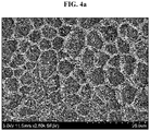
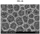
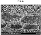
- the porous coating layer can be seen from SEM image.
- a separator having a porous coating layer is manufactured by the same method as example 1 except that a binder polymer solution is prepared using P(VDF-HFP-CTFE)terpolymer (vinylidene fluoride-trifluoroethylene-chlorofluoroethylene terpolymer) (weight average molecular weight: 500,000, containing 80 weight% of repeat units derived from vinylidenefluoride, 1 weight% of repeat units derived from hexafluoropropylene and 19 weight% of repeat units derived from chlorotrifluoroethylene).
- P(VDF-HFP-CTFE)terpolymer vinylene fluoride-trifluoroethylene-chlorofluoroethylene terpolymer
- weight average molecular weight 500,000, containing 80 weight% of repeat units derived from vinylidenefluoride, 1 weight% of repeat units derived from hexafluoropropylene and 19 weight% of repeat units derived from chlorotrifluoroethylene.
- a separator having a porous coating layer is manufactured by the same method as example 1 except that a binder polymer solution is prepared using P(VDF-HFP-CTFE)terpolymer (vinylidene fluoride-trifluoroethylene-chlorofluoroethylene terpolymer) (weight average molecular weight: 500,000, containing 73 weight% of repeat units derived from vinylidenefluoride, 1 weight% of repeat units derived from hexafluoropropylene and 26 weight% of repeat units derived from chlorotrifluoroethylene.
- P(VDF-HFP-CTFE)terpolymer vinylene fluoride-trifluoroethylene-chlorofluoroethylene terpolymer
- weight average molecular weight 500,000, containing 73 weight% of repeat units derived from vinylidenefluoride, 1 weight% of repeat units derived from hexafluoropropylene and 26 weight% of repeat units derived from chlorotrifluoroethylene.
- a separator having a porous coating layer is manufactured by the same method as example 1 except that a binder polymer solution is prepared using P(VDF-HFP-CTFE)terpolymer (vinylidene fluoride-trifluoroethylene-chlorofluoroethylene terpolymer) (weight average molecular weight: 500,000, containing 80 weight% of repeat units derived from vinylidenefluoride, 10 weight% of repeat units derived from hexafluoropropylene and 10 weight% of repeat units derived from chlorotrifluoroethylene).
- P(VDF-HFP-CTFE)terpolymer vinylene fluoride-trifluoroethylene-chlorofluoroethylene terpolymer
- weight average molecular weight 500,000, containing 80 weight% of repeat units derived from vinylidenefluoride, 10 weight% of repeat units derived from hexafluoropropylene and 10 weight% of repeat units derived from chlorotrifluoroethylene.
- a separator having a porous coating layer is manufactured by the same method as example 1 except that a binder polymer solution is prepared using P(VDF-HFP-CTFE)terpolymer (vinylidene fluoride-trifluoroethylene-chlorofluoroethylene terpolymer) (weight average molecular weight: 500,000, containing 80 weight% of repeat units derived from vinylidenefluoride, 15 weight% of repeat units derived from hexafluoropropylene and 5 weight% of repeat units derived from chlorotrifluoroethylene).
- P(VDF-HFP-CTFE)terpolymer vinylene fluoride-trifluoroethylene-chlorofluoroethylene terpolymer
- weight average molecular weight 500,000, containing 80 weight% of repeat units derived from vinylidenefluoride, 15 weight% of repeat units derived from hexafluoropropylene and 5 weight% of repeat units derived from chlorotrifluoroethylene.
- the binder polymer solution of example 1 is dip-coated on a 6 cm x 15 cm polyethylene porous substrate (thickness 9 ⁇ m, porosity 43%, air permeation time 110 sec, resistance 0.45 ⁇ ) at the rate of 2 cm/sec under the condition of 23 °C and 42% relative humidity.
- a separator is manufactured by the same method as example 1 except that instead of P(VDF-HFP-CTFE) terpolymer as binder polymer, a binder polymer solution is prepared using P(VDF-HFP) binder polymer (weight average molecular weight: 500,000) containing 15 weight% of repeat units derived from HFP and P(VDF-CTFE) binder polymer (weight average molecular weight: 450,000) containing 20 weight% of repeat units derived from CTFE, and adding P(VDF-HFP), P(VDF-CTFE), a dispersant and inorganic particles to a solvent at a weight ratio of 17:3:2:78.
- the binder polymer solution of comparative example 1 is dip-coated a 6 cm x 15 cm polyethylene porous substrate (thickness 9 ⁇ m, porosity 43%, air permeation time 110 sec, resistance 0.45 ⁇ ) at the rate of 2 cm/sec under the condition of 23°C and 42% relative humidity.
- a separator is manufactured by the same method as example 1 except that instead of P(VDF-HFP-CTFE), P(VDF-HFP) (weight average molecular weight: 450,000) containing 15 weight% of repeat units derived from HFP is used as the binder polymer.
- P(VDF-HFP-CTFE) weight average molecular weight: 450,000
- the binder polymer solution of comparative example 2 is dip-coated on a 6 cm x 15 cm polyethylene porous substrate (thickness 9 ⁇ m, porosity 43%, air permeation time 110 sec, resistance 0.45 ⁇ ) at the rate of 2 cm/sec under the condition of 23°C and 42% relative humidity.
- a separator is manufactured by the same method as example 1 except that instead of P(VDF-HFP-CTFE), P(VDF-HFP) containing 8 weight% of repeat units derived from HFP (weight average molecular weight: 450,000) is used as the binder polymer.
- the binder polymer solution of comparative example 3 is dip-coated on a 6 cm x 15 cm polyethylene porous substrate (thickness 9 ⁇ m, porosity 43%, air permeation time 110 sec, resistance 0.45 ⁇ ) at the rate of 2 cm/sec under the condition of 23°C and 42% relative humidity.
- a separator is manufactured by the same method as example 1 except that instead of P(VDF-HFP-CTFE), P(VDF-CTFE) containing 20 weight% of repeat units derived from CTFE (weight average molecular weight: 450,000) is used as the binder polymer.
- the binder polymer solution of comparative example 4 is dip-coated on a 6 cm x 15 cm polyethylene porous substrate (thickness 9 ⁇ m, porosity 43%, air permeation time 110 sec, resistance 0.45 ⁇ ) at the rate of 2 cm/sec under the condition of 23°C and 42% relative humidity.
- a separator having a porous coating layer is manufactured by the same method as example 1 except that a binder polymer solution is prepared using P(VDF-HFP-CTFE)terpolymer (vinylidene fluoride-trifluoroethylene-chlorofluoroethylene terpolymer) (weight average molecular weight: 450,000, containing 70 weight% of repeats unit derived from vinylidenefluoride, 1 weight% of repeats unit derived from hexafluoropropylene and 29 weight% of repeats unit derived from chlorotrifluoroethylene).
- P(VDF-HFP-CTFE)terpolymer vinylene fluoride-trifluoroethylene-chlorofluoroethylene terpolymer
- weight average molecular weight 450,000, containing 70 weight% of repeats unit derived from vinylidenefluoride, 1 weight% of repeats unit derived from hexafluoropropylene and 29 weight% of repeats unit derived from chlorotrifluor
- NMP N-methyl pyrrolidone
- a dispersant cyanoethyl polyvinylalcohol
- a ball mill method for 12 hours in total to prepare slurry for forming a porous coating layer.
- a ratio of solvents and solids is 9:1.
- the slurry for forming a porous coating layer is coated on two surfaces of a 6 cm x 15 cm polyethylene porous substrate (thickness 9 ⁇ m, porosity 43%, air permeation time 110 sec, resistance 0.45 ⁇ ) by dip coating under the condition of 23°C and 42% relative humidity such that the total coating amount on the two surfaces of the porous substrate is 13.5 g/m 2 , and immersed in a solution containing 50 vol% of a non-solvent, water, based on NMP for 30 seconds, followed by coagulation and washing. Subsequently, drying is performed with hot air using 100°C heat-gun to manufacture a separator.
- the porous coating layer of the separator has no interstitial volume, and the areas occupied by the solvent become pores by exchange between solvent and non-solvent.
- a separator having a porous coating layer is manufactured by the same method as comparative example 6 except that a binder polymer solution is prepared using P(VDF-HFP-CTFE)terpolymer (vinylidene fluoride-trifluoroethylene-chlorofluoroethylene terpolymer) (weight average molecular weight: 500,000, containing 80 weight% of repeats unit derived from vinylidenefluoride, 1 weight% of repeats unit derived from hexafluoropropylene and 19 weight% of repeats unit derived from chlorotrifluoroethylene).
- the porous coating layer of the separator has no interstitial volume, and the areas occupied by the solvent become pores by exchange between solvent and non-solvent.
- P(VDF-HFP-CTFE)terpolymer (vinylidene fluoride-trifluoroethylene-chlorofluoroethylene terpolymer) (weight average molecular weight: 500,000, containing 90 weight% of repeats unit derived from vinylidenefluoride, 5 weight% of repeats unit derived from hexafluoropropylene and 5 weight% of repeats unit derived from chlorotrifluoroethylene) is added to acetone and dissolved at 50°C for about 4 hours to prepare a binder polymer solution.
- a dispersant cyanoethyl polyvinylalcohol
- the inorganic particles are pulverized and dispersed using a ball mill method for 12 hours in total to prepare slurry for forming a porous coating layer.
- a ratio of solvents and solids is 4:1.
- the slurry for forming a porous coating layer is coated on two surfaces of a 6 cm x 15 cm polyethylene porous substrate (thickness 9 ⁇ m, porosity 43%, air permeation time 110 sec, resistance 0.45 ⁇ ) by dip coating under the condition of 23°C and 10% relative humidity such that the total coating amount on the two surfaces of the porous substrate is 13.5 g/m 2 and dried at 23°C for 1 minute to manufacture a separator. Some pores between adjacent inorganic particles of the separator are clogged by the binder, so the interstitial volumes are not uniformly formed.
- a separator having a porous coating layer is manufactured by the same method as example 1 except that a binder polymer solution is prepared using P(VDF-HFP-CTFE)terpolymer (vinylidene fluoride-trifluoroethylene-chlorofluoroethylene terpolymer) (weight average molecular weight: 500,000, containing 66 weight% of repeats unit derived from vinylidenefluoride, 29 weight% of repeats unit derived from hexafluoropropylene and 5 weight% of repeats unit derived from chlorotrifluoroethylene).
- P(VDF-HFP-CTFE)terpolymer vinylene fluoride-trifluoroethylene-chlorofluoroethylene terpolymer
- weight average molecular weight 500,000, containing 66 weight% of repeats unit derived from vinylidenefluoride, 29 weight% of repeats unit derived from hexafluoropropylene and 5 weight% of repeats unit derived from chlorotri
- Evaluation example 1 Observation of pore shape in porous coating layer
- the surface or cross section of the separator may be confirmed by imaging using a scanning electron microscopy (SEM).
- SEM scanning electron microscopy
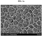
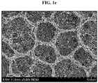
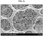
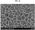
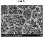
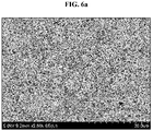
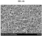
- reference example 1 and comparative reference examples 1 to 5 provide separators manufactured by coating and drying a coating composition containing no inorganic particle, a binder polymer solution, on a porous substrate. For each separator, image processing is performed on the pores present in the range of view width 60 ⁇ m, and a predetermined depth from the surface (for example, 1/5 to 1/100 of the thickness of the porous coating layer) to capture an image of the separator surface shape, and the results are shown in FIGS.
- FIGS. Id, 2d, 3c, 4c, 5c and 6c are shown in FIGS. Id, 2d, 3c, 4c, 5c and 6c.
- example 1 and reference example 1 using PVDF-HFP-CTFE terpolymer binder polymer has uniform micropores.
- the porous coating layer includes interstitial volumes between the inorganic particles corresponding to voids defined by substantial contact between adjacent inorganic particles.
- comparative example 1 and comparative reference example 1 using a combination of PVDF-HFP (HFP 15 wt%) and PVDF-CTFE (CTFE 20 wt%) as binder polymer have an irregular pore size.
- comparative example 2 and comparative reference example 2 using PVDF-HFP (HFP 15 wt%) alone as binder polymer have a relatively large pore size
- comparative example 3 and comparative reference example 3 using PVDF-HFP (HFP 8 wt%) alone as binder polymer have also a relatively large pore size.
- comparative example 4 and comparative reference example 4 using a combination of PVDF-HFP (HFP 8wt%) and PVDF-CTFE (CTFE 20 wt%) as binder polymer have an irregular pore size
- comparative example 5 using PVDF-CTFE (CTFE 20 wt%) alone as binder polymer fails to form appropriate pores since binder polymer precipitation occurs before internal pore formation due to the binder polymer being sensitive to phase separation.
- the separators manufactured in examples 1 to 5 and comparative examples 1 to 9 are tailored to the size of 25 mm x 70 mm.
- the prepared separator and the anode are overlapped with each other, interposed between a 100 ⁇ m PET film, and adhered using a flat plate press.
- the condition of the flat plate press is heat pressing at the temperature of 70°C and the pressure of 600 kgf for 1 second.
- the separator and the anode adhered to each other are attached to a slide glass using a double-sided tape.
- Part of the separator adhesive surface (10 mm or less from the end of the adhesive surface) is peeled off and adhered such that its longitudinal direction is connected to a 25 x 100 mm PET film using a single sided tape.
- a force is applied 180° at 300 mm/min with the slide glass being placed on a lower holder of UTM instrument (LLOYD Instrument LF Plus) and the PET film attached to the separator being placed on an upper holder of the UTM instrument, and a force required to separate the separator from the anode is measured.
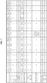
- the adhesiveness towards electrode is a value reflecting the adhesiveness level between the electrode and the coated separator, and the results are shown in FIG. 7 .
- EIS Electrochemical Impedance Spectroscopy
- air permeability is measured using a Gurley type air permeability tester.
- the time taken for 100 ml of air to pass through the separator is measured, and the results are shown in FIG. 7 .
- the separator samples obtained in each example or comparative example are cut to the size of 50 mm (length) x 50 mm (width) to prepare a test piece.
- the test piece is kept in an oven heated to 150°C for 30 minutes. Subsequently, the test piece is taken and its changed lengths in MD and TD are measured.
- Shrinkage % dimension before contraction ⁇ dimension after contraction / dimension before contraction ⁇ 100
- separators of examples 1 to 5 have good or excellent adhesiveness of 66 gf/24 mm or more towards negative electrode, and from this, it may be inferred that uniform micropores are formed on the surface of the separator of the present disclosure, and the separator has a wide specific surface area for contact with the electrode.
- comparative example 3 has the porous coating layer separated from the substrate due to the low adhesiveness with the substrate, and the separators of comparative examples 4 to 9 have low adhesiveness of 24 gf/24 mm or less towards negative electrode.
- separators of examples 1 to 5 have the resistance of 0.96 Ohm or less, whereas the separators of comparative examples 1 to 3, 8 and 9 have the resistance of 0.98 Ohm or more.
- separators of examples 1 to 5 have MD thermal shrinkage of 17% or less and TD thermal shrinkage of 16% or less
- the separators of comparative examples 2 and 4 to 8 have MD thermal shrinkage of 19% or more and TD thermal shrinkage of 18% or more.
- the separators of comparative example 6 to 8 including pores formed through phase transition and the separator of comparative example 9 having high HFP content in the terpolymer binder have high thermal shrinkage.
- the separator when the binder polymer of the present disclosure including repeat units derived from VDF-HFP-CTFE is used in the porous coating layer, the separator has good air permeability, adhesiveness towards electrode, resistance characteristics and thermal shrinkage.
- the surface region is defined as a region extending downwards from the surface to the bottom by 10% of the total thickness of the porous coating layer
- the bottom region is defined as a region extending upwards from the bottom of the porous coating layer to the surface by 10% of the total thickness of the porous coating layer.
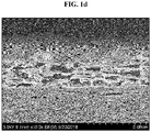
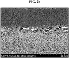
- the thickness of the porous coating layer of the separators of example 1 and comparative reference example 1 is divided into five region, the surface region extending downwards from the surface to the bottom by 10% of the total thickness of the porous coating layer is designated as Spectrum 1, the region extending upwards from the bottom of the porous coating layer to the surface by 10% of the total thickness of the porous coating layer is designated as Spectrum 5, Spectrum 1 and Spectrum 5 are equally divided into three in the thickness direction, and the three divisions are designated as Spectrum 2, Spectrum 3 and Spectrum 4 in an ascending order from Spectrum 1.
- the weight fraction of F (fluorine) and the weight fraction of Cl (chlorine) are determined by determining how much fluorine and chlorine are detected in the bottom region and the surface region of the separator cross section specimen having the porous coating layer using Energy Dispersive Spectrometer (EDS) attached to an electron microscope.
- EDS Energy Dispersive Spectrometer
- Example 1 Comparative example 1 F (wt%) Cl (wt% ) a a-b (a-b)/a x 100
- the Cl (chlorine) content in the surface region and the bottom region of the porous coating layer of example 1 is 34, showing uniform Cl (chlorine) distribution, namely uniform binder polymer distribution along the thickness of the porous coating layer, whereas the Cl (chlorine) content in the surface region and the bottom region of the porous coating layer of comparative example 1 amounts to 150, showing non-uniform Cl (chlorine) distribution, namely non-uniform binder polymer distribution along the thickness of the porous coating layer.
Landscapes
- Chemical & Material Sciences (AREA)
- Chemical Kinetics & Catalysis (AREA)
- Electrochemistry (AREA)
- General Chemical & Material Sciences (AREA)
- Engineering & Computer Science (AREA)
- Inorganic Chemistry (AREA)
- Manufacturing & Machinery (AREA)
- Composite Materials (AREA)
- Materials Engineering (AREA)
- Cell Separators (AREA)
- Ceramic Engineering (AREA)
Applications Claiming Priority (2)
| Application Number | Priority Date | Filing Date | Title |
|---|---|---|---|
| KR20180116543 | 2018-09-28 | ||
| PCT/KR2019/012770 WO2020067845A1 (fr) | 2018-09-28 | 2019-09-30 | Séparateur ayant une adhérence d'électrode et une propriété de résistance améliorées, pour batterie secondaire au lithium, et batterie secondaire au lithium comprenant ce séparateur |
Publications (3)
| Publication Number | Publication Date |
|---|---|
| EP3764426A1 true EP3764426A1 (fr) | 2021-01-13 |
| EP3764426A4 EP3764426A4 (fr) | 2021-05-26 |
| EP3764426B1 EP3764426B1 (fr) | 2024-07-24 |
Family
ID=69950689
Family Applications (1)
| Application Number | Title | Priority Date | Filing Date |
|---|---|---|---|
| EP19866774.3A Active EP3764426B1 (fr) | 2018-09-28 | 2019-09-30 | Séparateur pour batterie secondaire au lithium ayant une adhérence améliorée vis-à-vis d'électrode et des propriétés de résistance améliorées et batterie secondaire au lithium comprenant ce séparateur |
Country Status (7)
| Country | Link |
|---|---|
| US (2) | US11811093B2 (fr) |
| EP (1) | EP3764426B1 (fr) |
| KR (1) | KR102364467B1 (fr) |
| CN (1) | CN111566843B (fr) |
| ES (1) | ES2985877T3 (fr) |
| HU (1) | HUE067657T2 (fr) |
| WO (1) | WO2020067845A1 (fr) |
Families Citing this family (14)
| Publication number | Priority date | Publication date | Assignee | Title |
|---|---|---|---|---|
| US12142789B2 (en) * | 2019-02-28 | 2024-11-12 | Panasonic Intellectual Property Management Co., Ltd. | Non-aqueous electrolyte secondary battery |
| KR102814789B1 (ko) * | 2019-08-09 | 2025-05-28 | 주식회사 엘지에너지솔루션 | 다공성 분리막 및 이를 포함하는 전기화학소자 |
| US20230216145A1 (en) * | 2020-06-30 | 2023-07-06 | Lg Energy Solution, Ltd. | Separator for lithium secondary battery, manufacturing method therefor, and separator manufactured by same |
| CN115735298A (zh) * | 2020-07-01 | 2023-03-03 | 株式会社Lg新能源 | 制造隔板的方法和设备、和由其制造的隔板 |
| KR102825704B1 (ko) | 2020-08-13 | 2025-06-26 | 주식회사 엘지에너지솔루션 | PVAc-PMA 공중합체를 포함하는 전지용 고접착 분리막 및 이를 포함하는 이차전지 |
| WO2022224596A1 (fr) * | 2021-04-23 | 2022-10-27 | 株式会社村田製作所 | Batterie secondaire à électrolyte non aqueux |
| KR102626621B1 (ko) * | 2021-06-03 | 2024-01-17 | 성균관대학교산학협력단 | 리튬금속전지 및 이의 제조 방법 |
| KR20230115108A (ko) * | 2022-01-26 | 2023-08-02 | 주식회사 엘지화학 | 전기화학소자용 분리막 및 이를 포함하는 전기화학소자 |
| US20260074275A1 (en) * | 2022-08-10 | 2026-03-12 | Solvay Specialty Polymers Italy S.P.A. | Solid composite electrolyte |
| CN115566196B (zh) * | 2022-11-04 | 2025-12-19 | 无锡零一未来新材料技术研究院有限公司 | 一种锂电池硅负极用粘结剂、硅负极极片及锂电池 |
| CN116190910B (zh) * | 2022-12-23 | 2025-10-14 | 力神(青岛)新能源有限公司 | 涂布浆料及制备方法、隔膜、锂电池和用电设备 |
| KR102805563B1 (ko) * | 2023-04-04 | 2025-05-09 | 국립부경대학교 산학협력단 | 충전-방전성능 및 열 안정성을 향상시킨 리튬이온 이차전지용 분리막 및 그 제조방법 |
| CN116577392B (zh) * | 2023-05-10 | 2026-04-14 | 江苏海洋大学 | 一种可同时检测黄芩素和木犀草素的自支撑式柔性电极的制备方法及其应用 |
| JP2025536071A (ja) * | 2023-08-22 | 2025-10-30 | エルジー・ケム・リミテッド | リチウム二次電池用電極一体型分離膜およびその製造方法 |
Family Cites Families (29)
| Publication number | Priority date | Publication date | Assignee | Title |
|---|---|---|---|---|
| US3341366A (en) * | 1964-08-19 | 1967-09-12 | Gen Electric | Sulfonated polymers of alpha, beta, beta-trifluorostyrene, with applications to structures and cells |
| KR100367284B1 (ko) * | 1999-02-22 | 2003-01-09 | 티디케이가부시기가이샤 | 2차전지 및 그 제조방법 |
| JP5171150B2 (ja) | 2000-03-07 | 2013-03-27 | 帝人株式会社 | リチウムイオン二次電池用セパレータ |
| US6881438B2 (en) | 2000-03-07 | 2005-04-19 | Teijin Limited | Process for production of composite porous film |
| CA2373904C (fr) * | 2000-03-07 | 2010-01-26 | Teijin Limited | Batterie secondaire au lithium-ion, separateur, bloc-batterie et methode de charge |
| SG103298A1 (en) * | 2000-06-16 | 2004-04-29 | Nisshin Spinning | Polymer battery and method of manufacture |
| GB0018635D0 (en) * | 2000-07-31 | 2000-09-13 | Aea Technology Plc | Polymer electrolyte |
| FR2812294B1 (fr) * | 2000-07-31 | 2003-01-17 | Solvay | Polymeres du fluorure de vinylidene, procede pour les fabriquer et utilisation de ceux-ci |
| US20060134525A1 (en) * | 2002-09-27 | 2006-06-22 | Christian Kleijnen | Rechargeable lithium battery |
| JP5023649B2 (ja) * | 2006-10-13 | 2012-09-12 | ソニー株式会社 | リチウムイオン二次電池 |
| JP5369171B2 (ja) * | 2009-03-09 | 2013-12-18 | 旭化成イーマテリアルズ株式会社 | 積層セパレータ及びその製造方法 |
| EP2445041B1 (fr) * | 2009-06-17 | 2016-04-13 | Sony Corporation | Batterie à électrolyte non aqueux, électrode positive pour batterie à électrolyte non aqueux, électrode négative pour batterie à électrolyte non aqueux, séparateur pour batterie à électrolyte non aqueux, électrolyte pour batterie à électrolyte non aqueux et procédé de production de séparateur pour batterie à électrolyte non aqueux |
| WO2011096564A1 (fr) * | 2010-02-05 | 2011-08-11 | ダイキン工業株式会社 | Film composite d'électrolyte en gel pour batterie secondaire et batterie secondaire |
| EP2551293A4 (fr) * | 2010-03-24 | 2016-08-03 | Teijin Ltd | Membrane microporeuse en polyoléfines, l'une de ses méthodes de production, séparateur pour piles secondaires non aqueuses et pile secondaire non aqueuse |
| JP5699559B2 (ja) * | 2010-11-17 | 2015-04-15 | ソニー株式会社 | 非水電解質電池 |
| KR101981825B1 (ko) * | 2011-11-17 | 2019-05-23 | 솔베이 스페셜티 폴리머스 이태리 에스.피.에이. | 고분자 전해질 세퍼레이터의 제조 방법 및 그로부터의 고분자 전해질 세퍼레이터 |
| CN104396048B (zh) * | 2012-11-02 | 2018-08-14 | 阿科玛股份有限公司 | 用于锂离子电池的整合式电极隔膜组件 |
| CN105900262B (zh) * | 2013-05-15 | 2019-03-12 | 株式会社吴羽 | 非水电解质二次电池用结构体、非水电解质二次电池以及该结构体的制造方法 |
| JP6165036B2 (ja) * | 2013-11-27 | 2017-07-19 | 株式会社クレハ | フッ化ビニリデン系重合体水系組成物およびその用途 |
| KR101785263B1 (ko) | 2013-12-02 | 2017-10-16 | 삼성에스디아이 주식회사 | 바인더 조성물, 이에 의해 형성된 바인더를 포함하는 세퍼레이터, 상기 세퍼레이터를 포함하는 리튬 전지, 및 상기 바인더 조성물의 제조방법 |
| US9979011B2 (en) * | 2014-09-26 | 2018-05-22 | The United States Of America As Represented By The Secretary Of The Army | LixMn2O4-y(C1z) spinal cathode material, method of preparing the same, and rechargeable lithium and li-ion electrochemical systems containing the same |
| EP3866244A1 (fr) | 2014-12-05 | 2021-08-18 | Celgard, LLC | Séparateurs revêtus améliorés pour batteries au lithium, et procédés correspondants |
| US11643484B2 (en) * | 2015-03-16 | 2023-05-09 | Arkema Inc. | Modified fluoropolymers |
| KR101998832B1 (ko) * | 2015-08-25 | 2019-09-27 | 주식회사 엘지화학 | 접착층을 포함하는 전기화학소자용 복합 분리막 및 이를 포함하는 전기화학소자 |
| PL3376562T3 (pl) | 2015-11-11 | 2020-06-01 | Teijin Limited | Separator do bezwodnej dodatkowej baterii i bezwodna dodatkowa bateria |
| CN108352486A (zh) * | 2015-11-11 | 2018-07-31 | 帝人株式会社 | 非水系二次电池用隔膜及非水系二次电池 |
| KR102005870B1 (ko) | 2016-01-15 | 2019-07-31 | 삼성에스디아이 주식회사 | 이차 전지용 세퍼레이터 및 이를 포함하는 리튬 이차 전지 |
| KR102069354B1 (ko) | 2016-10-04 | 2020-01-22 | 주식회사 엘지화학 | 열 안전성이 개선된 전극조립체 |
| KR20180116543A (ko) | 2017-04-17 | 2018-10-25 | (주)아모레퍼시픽 | 신규한 하이퍼브랜치 형태의 폴리글리세롤계 화합물 및 이를 포함하는 화장료 조성물 |
-
2019
- 2019-09-30 ES ES19866774T patent/ES2985877T3/es active Active
- 2019-09-30 US US17/044,364 patent/US11811093B2/en active Active
- 2019-09-30 CN CN201980006935.1A patent/CN111566843B/zh active Active
- 2019-09-30 HU HUE19866774A patent/HUE067657T2/hu unknown
- 2019-09-30 EP EP19866774.3A patent/EP3764426B1/fr active Active
- 2019-09-30 WO PCT/KR2019/012770 patent/WO2020067845A1/fr not_active Ceased
- 2019-09-30 KR KR1020190121132A patent/KR102364467B1/ko active Active
-
2023
- 2023-09-25 US US18/372,682 patent/US12255354B2/en active Active
Also Published As
| Publication number | Publication date |
|---|---|
| ES2985877T3 (es) | 2024-11-07 |
| KR20200036803A (ko) | 2020-04-07 |
| US12255354B2 (en) | 2025-03-18 |
| KR102364467B1 (ko) | 2022-02-17 |
| CN111566843B (zh) | 2023-01-24 |
| US20210098847A1 (en) | 2021-04-01 |
| US20240021960A1 (en) | 2024-01-18 |
| HUE067657T2 (hu) | 2024-11-28 |
| EP3764426B1 (fr) | 2024-07-24 |
| CN111566843A (zh) | 2020-08-21 |
| US11811093B2 (en) | 2023-11-07 |
| WO2020067845A1 (fr) | 2020-04-02 |
| EP3764426A4 (fr) | 2021-05-26 |
Similar Documents
| Publication | Publication Date | Title |
|---|---|---|
| US12255354B2 (en) | Separator for lithium secondary battery with improved adhesiveness towards electrode and resistance characteristics and lithium secondary battery comprising the separator | |
| KR102086129B1 (ko) | 세퍼레이터 및 이를 포함하는 전기화학소자 | |
| EP3832758B1 (fr) | Séparateur pour accumulateur au lithium | |
| EP3734701A1 (fr) | Séparateur et dispositif électrochimique le comprenant | |
| US12255352B2 (en) | Lithium secondary battery separator having enhanced adhesive strength to electrode and improved resistance characteristics, and lithium secondary battery comprising lithium secondary battery separator | |
| JP7359937B2 (ja) | 改善された電極接着力及び抵抗特性を有するリチウム二次電池用分離膜及び該分離膜を含むリチウム二次電池 | |
| US10637028B2 (en) | Separator and electrochemical device comprising same | |
| EP3367465A1 (fr) | Séparateur et dispositif électrochimique le comprenant | |
| EP4050721B1 (fr) | Séparateur pour dispositif électrochimique, et dispositif électrochimique comprenant celui-ci | |
| KR20190069338A (ko) | 세퍼레이터 및 이를 포함하는 전기화학소자 | |
| EP3553869A1 (fr) | Ensemble d'électrodes et dispositif électrochimique le comprenant | |
| EP3832756B1 (fr) | Procédé de fabrication de séparateur destiné à un dispositif électrochimique | |
| EP3979355A1 (fr) | Séparateur et dispositif électrochimique le comprenant | |
| KR102684714B1 (ko) | 다공성 분리막 및 이를 포함하는 전기화학소자 | |
| KR20230172737A (ko) | 리튬 이차 전지용 세퍼레이터 및 이를 포함하는 리튬 이차 전지 |
Legal Events
| Date | Code | Title | Description |
|---|---|---|---|
| STAA | Information on the status of an ep patent application or granted ep patent |
Free format text: STATUS: THE INTERNATIONAL PUBLICATION HAS BEEN MADE |
|
| PUAI | Public reference made under article 153(3) epc to a published international application that has entered the european phase |
Free format text: ORIGINAL CODE: 0009012 |
|
| STAA | Information on the status of an ep patent application or granted ep patent |
Free format text: STATUS: REQUEST FOR EXAMINATION WAS MADE |
|
| 17P | Request for examination filed |
Effective date: 20201006 |
|
| AK | Designated contracting states |
Kind code of ref document: A1 Designated state(s): AL AT BE BG CH CY CZ DE DK EE ES FI FR GB GR HR HU IE IS IT LI LT LU LV MC MK MT NL NO PL PT RO RS SE SI SK SM TR |
|
| AX | Request for extension of the european patent |
Extension state: BA ME |
|
| A4 | Supplementary search report drawn up and despatched |
Effective date: 20210429 |
|
| RIC1 | Information provided on ipc code assigned before grant |
Ipc: H01M 50/446 20210101AFI20210422BHEP Ipc: H01M 10/052 20100101ALI20210422BHEP Ipc: H01M 50/417 20210101ALI20210422BHEP Ipc: H01M 50/426 20210101ALI20210422BHEP Ipc: H01M 50/431 20210101ALI20210422BHEP Ipc: H01M 50/449 20210101ALI20210422BHEP Ipc: H01M 50/466 20210101ALI20210422BHEP Ipc: H01M 50/457 20210101ALI20210422BHEP |
|
| DAV | Request for validation of the european patent (deleted) | ||
| DAX | Request for extension of the european patent (deleted) | ||
| RAP1 | Party data changed (applicant data changed or rights of an application transferred) |
Owner name: LG ENERGY SOLUTION LTD. |
|
| RAP3 | Party data changed (applicant data changed or rights of an application transferred) |
Owner name: LG ENERGY SOLUTION, LTD. |
|
| REG | Reference to a national code |
Ref country code: DE Free format text: PREVIOUS MAIN CLASS: H01M0002160000 Ref country code: DE Ref legal event code: R079 Ref document number: 602019055879 Country of ref document: DE Free format text: PREVIOUS MAIN CLASS: H01M0002160000 Ipc: H01M0050446000 |
|
| GRAP | Despatch of communication of intention to grant a patent |
Free format text: ORIGINAL CODE: EPIDOSNIGR1 |
|
| STAA | Information on the status of an ep patent application or granted ep patent |
Free format text: STATUS: GRANT OF PATENT IS INTENDED |
|
| RIC1 | Information provided on ipc code assigned before grant |
Ipc: H01M 50/443 20210101ALI20240211BHEP Ipc: H01M 50/457 20210101ALI20240211BHEP Ipc: H01M 50/466 20210101ALI20240211BHEP Ipc: H01M 50/449 20210101ALI20240211BHEP Ipc: H01M 50/431 20210101ALI20240211BHEP Ipc: H01M 50/426 20210101ALI20240211BHEP Ipc: H01M 50/417 20210101ALI20240211BHEP Ipc: H01M 10/052 20100101ALI20240211BHEP Ipc: H01M 50/446 20210101AFI20240211BHEP |
|
| INTG | Intention to grant announced |
Effective date: 20240229 |
|
| GRAS | Grant fee paid |
Free format text: ORIGINAL CODE: EPIDOSNIGR3 |
|
| GRAA | (expected) grant |
Free format text: ORIGINAL CODE: 0009210 |
|
| STAA | Information on the status of an ep patent application or granted ep patent |
Free format text: STATUS: THE PATENT HAS BEEN GRANTED |
|
| AK | Designated contracting states |
Kind code of ref document: B1 Designated state(s): AL AT BE BG CH CY CZ DE DK EE ES FI FR GB GR HR HU IE IS IT LI LT LU LV MC MK MT NL NO PL PT RO RS SE SI SK SM TR |
|
| P01 | Opt-out of the competence of the unified patent court (upc) registered |
Free format text: CASE NUMBER: APP_36512/2024 Effective date: 20240618 |
|
| REG | Reference to a national code |
Ref country code: GB Ref legal event code: FG4D |
|
| REG | Reference to a national code |
Ref country code: CH Ref legal event code: EP |
|
| REG | Reference to a national code |
Ref country code: IE Ref legal event code: FG4D Ref country code: DE Ref legal event code: R096 Ref document number: 602019055879 Country of ref document: DE |
|
| REG | Reference to a national code |
Ref country code: ES Ref legal event code: FG2A Ref document number: 2985877 Country of ref document: ES Kind code of ref document: T3 Effective date: 20241107 |
|
| REG | Reference to a national code |
Ref country code: LT Ref legal event code: MG9D |
|
| REG | Reference to a national code |
Ref country code: NL Ref legal event code: MP Effective date: 20240724 |
|
| REG | Reference to a national code |
Ref country code: HU Ref legal event code: AG4A Ref document number: E067657 Country of ref document: HU |
|
| PG25 | Lapsed in a contracting state [announced via postgrant information from national office to epo] |
Ref country code: PT Free format text: LAPSE BECAUSE OF FAILURE TO SUBMIT A TRANSLATION OF THE DESCRIPTION OR TO PAY THE FEE WITHIN THE PRESCRIBED TIME-LIMIT Effective date: 20241125 |
|
| REG | Reference to a national code |
Ref country code: AT Ref legal event code: MK05 Ref document number: 1707178 Country of ref document: AT Kind code of ref document: T Effective date: 20240724 |
|
| PG25 | Lapsed in a contracting state [announced via postgrant information from national office to epo] |
Ref country code: NL Free format text: LAPSE BECAUSE OF FAILURE TO SUBMIT A TRANSLATION OF THE DESCRIPTION OR TO PAY THE FEE WITHIN THE PRESCRIBED TIME-LIMIT Effective date: 20240724 |
|
| PG25 | Lapsed in a contracting state [announced via postgrant information from national office to epo] |
Ref country code: PT Free format text: LAPSE BECAUSE OF FAILURE TO SUBMIT A TRANSLATION OF THE DESCRIPTION OR TO PAY THE FEE WITHIN THE PRESCRIBED TIME-LIMIT Effective date: 20241125 Ref country code: NL Free format text: LAPSE BECAUSE OF FAILURE TO SUBMIT A TRANSLATION OF THE DESCRIPTION OR TO PAY THE FEE WITHIN THE PRESCRIBED TIME-LIMIT Effective date: 20240724 |
|
| PG25 | Lapsed in a contracting state [announced via postgrant information from national office to epo] |
Ref country code: NO Free format text: LAPSE BECAUSE OF FAILURE TO SUBMIT A TRANSLATION OF THE DESCRIPTION OR TO PAY THE FEE WITHIN THE PRESCRIBED TIME-LIMIT Effective date: 20241024 |
|
| PG25 | Lapsed in a contracting state [announced via postgrant information from national office to epo] |
Ref country code: GR Free format text: LAPSE BECAUSE OF FAILURE TO SUBMIT A TRANSLATION OF THE DESCRIPTION OR TO PAY THE FEE WITHIN THE PRESCRIBED TIME-LIMIT Effective date: 20241025 Ref country code: FI Free format text: LAPSE BECAUSE OF FAILURE TO SUBMIT A TRANSLATION OF THE DESCRIPTION OR TO PAY THE FEE WITHIN THE PRESCRIBED TIME-LIMIT Effective date: 20240724 Ref country code: PL Free format text: LAPSE BECAUSE OF FAILURE TO SUBMIT A TRANSLATION OF THE DESCRIPTION OR TO PAY THE FEE WITHIN THE PRESCRIBED TIME-LIMIT Effective date: 20240724 |
|
| PG25 | Lapsed in a contracting state [announced via postgrant information from national office to epo] |
Ref country code: BG Free format text: LAPSE BECAUSE OF FAILURE TO SUBMIT A TRANSLATION OF THE DESCRIPTION OR TO PAY THE FEE WITHIN THE PRESCRIBED TIME-LIMIT Effective date: 20240724 |
|
| PG25 | Lapsed in a contracting state [announced via postgrant information from national office to epo] |
Ref country code: LV Free format text: LAPSE BECAUSE OF FAILURE TO SUBMIT A TRANSLATION OF THE DESCRIPTION OR TO PAY THE FEE WITHIN THE PRESCRIBED TIME-LIMIT Effective date: 20240724 |
|
| PG25 | Lapsed in a contracting state [announced via postgrant information from national office to epo] |
Ref country code: IS Free format text: LAPSE BECAUSE OF FAILURE TO SUBMIT A TRANSLATION OF THE DESCRIPTION OR TO PAY THE FEE WITHIN THE PRESCRIBED TIME-LIMIT Effective date: 20241124 Ref country code: AT Free format text: LAPSE BECAUSE OF FAILURE TO SUBMIT A TRANSLATION OF THE DESCRIPTION OR TO PAY THE FEE WITHIN THE PRESCRIBED TIME-LIMIT Effective date: 20240724 |
|
| PG25 | Lapsed in a contracting state [announced via postgrant information from national office to epo] |
Ref country code: HR Free format text: LAPSE BECAUSE OF FAILURE TO SUBMIT A TRANSLATION OF THE DESCRIPTION OR TO PAY THE FEE WITHIN THE PRESCRIBED TIME-LIMIT Effective date: 20240724 |
|
| PG25 | Lapsed in a contracting state [announced via postgrant information from national office to epo] |
Ref country code: RS Free format text: LAPSE BECAUSE OF FAILURE TO SUBMIT A TRANSLATION OF THE DESCRIPTION OR TO PAY THE FEE WITHIN THE PRESCRIBED TIME-LIMIT Effective date: 20241024 |
|
| PG25 | Lapsed in a contracting state [announced via postgrant information from national office to epo] |
Ref country code: RS Free format text: LAPSE BECAUSE OF FAILURE TO SUBMIT A TRANSLATION OF THE DESCRIPTION OR TO PAY THE FEE WITHIN THE PRESCRIBED TIME-LIMIT Effective date: 20241024 Ref country code: PL Free format text: LAPSE BECAUSE OF FAILURE TO SUBMIT A TRANSLATION OF THE DESCRIPTION OR TO PAY THE FEE WITHIN THE PRESCRIBED TIME-LIMIT Effective date: 20240724 Ref country code: NO Free format text: LAPSE BECAUSE OF FAILURE TO SUBMIT A TRANSLATION OF THE DESCRIPTION OR TO PAY THE FEE WITHIN THE PRESCRIBED TIME-LIMIT Effective date: 20241024 Ref country code: LV Free format text: LAPSE BECAUSE OF FAILURE TO SUBMIT A TRANSLATION OF THE DESCRIPTION OR TO PAY THE FEE WITHIN THE PRESCRIBED TIME-LIMIT Effective date: 20240724 Ref country code: IS Free format text: LAPSE BECAUSE OF FAILURE TO SUBMIT A TRANSLATION OF THE DESCRIPTION OR TO PAY THE FEE WITHIN THE PRESCRIBED TIME-LIMIT Effective date: 20241124 Ref country code: HR Free format text: LAPSE BECAUSE OF FAILURE TO SUBMIT A TRANSLATION OF THE DESCRIPTION OR TO PAY THE FEE WITHIN THE PRESCRIBED TIME-LIMIT Effective date: 20240724 Ref country code: GR Free format text: LAPSE BECAUSE OF FAILURE TO SUBMIT A TRANSLATION OF THE DESCRIPTION OR TO PAY THE FEE WITHIN THE PRESCRIBED TIME-LIMIT Effective date: 20241025 Ref country code: FI Free format text: LAPSE BECAUSE OF FAILURE TO SUBMIT A TRANSLATION OF THE DESCRIPTION OR TO PAY THE FEE WITHIN THE PRESCRIBED TIME-LIMIT Effective date: 20240724 Ref country code: BG Free format text: LAPSE BECAUSE OF FAILURE TO SUBMIT A TRANSLATION OF THE DESCRIPTION OR TO PAY THE FEE WITHIN THE PRESCRIBED TIME-LIMIT Effective date: 20240724 Ref country code: AT Free format text: LAPSE BECAUSE OF FAILURE TO SUBMIT A TRANSLATION OF THE DESCRIPTION OR TO PAY THE FEE WITHIN THE PRESCRIBED TIME-LIMIT Effective date: 20240724 |
|
| PG25 | Lapsed in a contracting state [announced via postgrant information from national office to epo] |
Ref country code: RO Free format text: LAPSE BECAUSE OF FAILURE TO SUBMIT A TRANSLATION OF THE DESCRIPTION OR TO PAY THE FEE WITHIN THE PRESCRIBED TIME-LIMIT Effective date: 20240724 Ref country code: DK Free format text: LAPSE BECAUSE OF FAILURE TO SUBMIT A TRANSLATION OF THE DESCRIPTION OR TO PAY THE FEE WITHIN THE PRESCRIBED TIME-LIMIT Effective date: 20240724 Ref country code: SM Free format text: LAPSE BECAUSE OF FAILURE TO SUBMIT A TRANSLATION OF THE DESCRIPTION OR TO PAY THE FEE WITHIN THE PRESCRIBED TIME-LIMIT Effective date: 20240724 |
|
| PG25 | Lapsed in a contracting state [announced via postgrant information from national office to epo] |
Ref country code: MC Free format text: LAPSE BECAUSE OF FAILURE TO SUBMIT A TRANSLATION OF THE DESCRIPTION OR TO PAY THE FEE WITHIN THE PRESCRIBED TIME-LIMIT Effective date: 20240724 Ref country code: EE Free format text: LAPSE BECAUSE OF FAILURE TO SUBMIT A TRANSLATION OF THE DESCRIPTION OR TO PAY THE FEE WITHIN THE PRESCRIBED TIME-LIMIT Effective date: 20240724 |
|
| PG25 | Lapsed in a contracting state [announced via postgrant information from national office to epo] |
Ref country code: CZ Free format text: LAPSE BECAUSE OF FAILURE TO SUBMIT A TRANSLATION OF THE DESCRIPTION OR TO PAY THE FEE WITHIN THE PRESCRIBED TIME-LIMIT Effective date: 20240724 |
|
| REG | Reference to a national code |
Ref country code: DE Ref legal event code: R097 Ref document number: 602019055879 Country of ref document: DE |
|
| PG25 | Lapsed in a contracting state [announced via postgrant information from national office to epo] |
Ref country code: IT Free format text: LAPSE BECAUSE OF FAILURE TO SUBMIT A TRANSLATION OF THE DESCRIPTION OR TO PAY THE FEE WITHIN THE PRESCRIBED TIME-LIMIT Effective date: 20240724 Ref country code: SK Free format text: LAPSE BECAUSE OF FAILURE TO SUBMIT A TRANSLATION OF THE DESCRIPTION OR TO PAY THE FEE WITHIN THE PRESCRIBED TIME-LIMIT Effective date: 20240724 |
|
| REG | Reference to a national code |
Ref country code: CH Ref legal event code: PL |
|
| PG25 | Lapsed in a contracting state [announced via postgrant information from national office to epo] |
Ref country code: LU Free format text: LAPSE BECAUSE OF NON-PAYMENT OF DUE FEES Effective date: 20240930 |
|
| PLBE | No opposition filed within time limit |
Free format text: ORIGINAL CODE: 0009261 |
|
| STAA | Information on the status of an ep patent application or granted ep patent |
Free format text: STATUS: NO OPPOSITION FILED WITHIN TIME LIMIT |
|
| 26N | No opposition filed |
Effective date: 20250425 |
|
| PG25 | Lapsed in a contracting state [announced via postgrant information from national office to epo] |
Ref country code: CH Free format text: LAPSE BECAUSE OF NON-PAYMENT OF DUE FEES Effective date: 20240930 |
|
| PG25 | Lapsed in a contracting state [announced via postgrant information from national office to epo] |
Ref country code: IE Free format text: LAPSE BECAUSE OF NON-PAYMENT OF DUE FEES Effective date: 20240930 |
|
| PG25 | Lapsed in a contracting state [announced via postgrant information from national office to epo] |
Ref country code: SE Free format text: LAPSE BECAUSE OF FAILURE TO SUBMIT A TRANSLATION OF THE DESCRIPTION OR TO PAY THE FEE WITHIN THE PRESCRIBED TIME-LIMIT Effective date: 20240724 |
|
| PGFP | Annual fee paid to national office [announced via postgrant information from national office to epo] |
Ref country code: DE Payment date: 20250820 Year of fee payment: 7 |
|
| PGFP | Annual fee paid to national office [announced via postgrant information from national office to epo] |
Ref country code: HU Payment date: 20250929 Year of fee payment: 7 Ref country code: BE Payment date: 20250820 Year of fee payment: 7 Ref country code: GB Payment date: 20250820 Year of fee payment: 7 |
|
| PGFP | Annual fee paid to national office [announced via postgrant information from national office to epo] |
Ref country code: FR Payment date: 20250821 Year of fee payment: 7 |
|
| PG25 | Lapsed in a contracting state [announced via postgrant information from national office to epo] |
Ref country code: CY Free format text: LAPSE BECAUSE OF FAILURE TO SUBMIT A TRANSLATION OF THE DESCRIPTION OR TO PAY THE FEE WITHIN THE PRESCRIBED TIME-LIMIT; INVALID AB INITIO Effective date: 20190930 |
|
| PGFP | Annual fee paid to national office [announced via postgrant information from national office to epo] |
Ref country code: ES Payment date: 20251007 Year of fee payment: 7 |