EP3764561B1 - Verfahren zur übertragung eines sounding-referenzsignals, endgerät und computerlesbares speichermedium - Google Patents
Verfahren zur übertragung eines sounding-referenzsignals, endgerät und computerlesbares speichermedium Download PDFInfo
- Publication number
- EP3764561B1 EP3764561B1 EP18913470.3A EP18913470A EP3764561B1 EP 3764561 B1 EP3764561 B1 EP 3764561B1 EP 18913470 A EP18913470 A EP 18913470A EP 3764561 B1 EP3764561 B1 EP 3764561B1
- Authority
- EP
- European Patent Office
- Prior art keywords
- srs
- antenna
- sequence number
- sending
- antenna group
- Prior art date
- Legal status (The legal status is an assumption and is not a legal conclusion. Google has not performed a legal analysis and makes no representation as to the accuracy of the status listed.)
- Active
Links
Images










Classifications
-
- H—ELECTRICITY
- H04—ELECTRIC COMMUNICATION TECHNIQUE
- H04B—TRANSMISSION
- H04B7/00—Radio transmission systems, i.e. using radiation field
- H04B7/02—Diversity systems; Multi-antenna system, i.e. transmission or reception using multiple antennas
- H04B7/04—Diversity systems; Multi-antenna system, i.e. transmission or reception using multiple antennas using two or more spaced independent antennas
- H04B7/06—Diversity systems; Multi-antenna system, i.e. transmission or reception using multiple antennas using two or more spaced independent antennas at the transmitting station
- H04B7/0686—Hybrid systems, i.e. switching and simultaneous transmission
- H04B7/0691—Hybrid systems, i.e. switching and simultaneous transmission using subgroups of transmit antennas
-
- H—ELECTRICITY
- H04—ELECTRIC COMMUNICATION TECHNIQUE
- H04B—TRANSMISSION
- H04B7/00—Radio transmission systems, i.e. using radiation field
- H04B7/02—Diversity systems; Multi-antenna system, i.e. transmission or reception using multiple antennas
- H04B7/04—Diversity systems; Multi-antenna system, i.e. transmission or reception using multiple antennas using two or more spaced independent antennas
- H04B7/0413—MIMO systems
- H04B7/0456—Selection of precoding matrices or codebooks, e.g. using matrices antenna weighting
- H04B7/046—Selection of precoding matrices or codebooks, e.g. using matrices antenna weighting taking physical layer constraints into account
- H04B7/0473—Selection of precoding matrices or codebooks, e.g. using matrices antenna weighting taking physical layer constraints into account taking constraints in layer or codeword to antenna mapping into account
-
- H—ELECTRICITY
- H04—ELECTRIC COMMUNICATION TECHNIQUE
- H04B—TRANSMISSION
- H04B7/00—Radio transmission systems, i.e. using radiation field
- H04B7/02—Diversity systems; Multi-antenna system, i.e. transmission or reception using multiple antennas
- H04B7/04—Diversity systems; Multi-antenna system, i.e. transmission or reception using multiple antennas using two or more spaced independent antennas
- H04B7/06—Diversity systems; Multi-antenna system, i.e. transmission or reception using multiple antennas using two or more spaced independent antennas at the transmitting station
- H04B7/0602—Diversity systems; Multi-antenna system, i.e. transmission or reception using multiple antennas using two or more spaced independent antennas at the transmitting station using antenna switching
- H04B7/0604—Diversity systems; Multi-antenna system, i.e. transmission or reception using multiple antennas using two or more spaced independent antennas at the transmitting station using antenna switching with predefined switching scheme
-
- H—ELECTRICITY
- H04—ELECTRIC COMMUNICATION TECHNIQUE
- H04L—TRANSMISSION OF DIGITAL INFORMATION, e.g. TELEGRAPHIC COMMUNICATION
- H04L5/00—Arrangements affording multiple use of the transmission path
- H04L5/0001—Arrangements for dividing the transmission path
- H04L5/0003—Two-dimensional division
- H04L5/0005—Time-frequency
- H04L5/0007—Time-frequency the frequencies being orthogonal, e.g. OFDM(A) or DMT
- H04L5/0012—Hopping in multicarrier systems
-
- H—ELECTRICITY
- H04—ELECTRIC COMMUNICATION TECHNIQUE
- H04L—TRANSMISSION OF DIGITAL INFORMATION, e.g. TELEGRAPHIC COMMUNICATION
- H04L5/00—Arrangements affording multiple use of the transmission path
- H04L5/0001—Arrangements for dividing the transmission path
- H04L5/0014—Three-dimensional division
- H04L5/0023—Time-frequency-space
-
- H—ELECTRICITY
- H04—ELECTRIC COMMUNICATION TECHNIQUE
- H04L—TRANSMISSION OF DIGITAL INFORMATION, e.g. TELEGRAPHIC COMMUNICATION
- H04L5/00—Arrangements affording multiple use of the transmission path
- H04L5/003—Arrangements for allocating sub-channels of the transmission path
- H04L5/0048—Allocation of pilot signals, i.e. of signals known to the receiver
Definitions
- This application relates to the communications field, and more specifically, to a sounding reference signal transmission method, a terminal device, and a computer-readable storage medium.
- a sounding reference signal (sounding reference signal, SRS) is a signal for measuring channel state information (channel state information, CSI) between a terminal device and a network device.
- the terminal device sends an SRS on an antenna to obtain uplink channel state information corresponding to each antenna, and the network device estimates, based on the received SRS, an uplink channel state corresponding to each antenna.
- the terminal device When a plurality of receive antennas are configured for the terminal device, to obtain complete channel information corresponding to all the antennas, the terminal device needs to perform antenna switching (namely, antenna selection) between the plurality of antennas for SRS transmission.
- antenna switching namely, antenna selection
- An existing LTE protocol supports 1T2R antenna selection. To be specific, at a same moment, the terminal device selects one antenna from two antennas according to an antenna selection formula for SRS transmission.
- a terminal device supporting 2T4R needs to select two antennas (one antenna group) from four antennas at a same moment for SRS transmission.
- the four antennas may be grouped into two antenna groups, or may be grouped into three antenna groups.
- the 1T2R antenna selection formula supported by the existing LTE protocol is not applicable to SRS antenna selection for three antenna groups.
- From WO 2010/008897 A1 communication systems involving antenna selection based on frequency-hopped sounding reference signals are known.
- WO 2010/082756 A2 multi antenna communication systems involving transmitting sounding reference signals are known.
- This application provides a sounding reference signal transmission method, a terminal device, and a computer-readable storage medium, to support SRS antenna selection for three antenna groups. To that end, a sounding reference signal transmission method according to the independent claim is provided.
- Dependent claims provide preferred embodiments and a corresponding terminal device, a chip and a computer-readable storage medium, respectively.
- NB-IoT narrowband internet of things
- GSM global system for mobile communications
- CDMA code division multiple access
- WCDMA wideband code division multiple access
- general packet radio service general packet radio service, GPRS
- LTE long term evolution
- LTE frequency division duplex frequency division duplex
- FDD frequency division duplex
- TDD time division duplex
- UMTS universal mobile telecommunications system
- WiMAX worldwide interoperability for microwave access
- a type of a terminal device is not specifically limited in the embodiments of this application, and the terminal device may be any device configured to communicate with a network device.
- the terminal device may be, for example, user equipment, an access terminal, a terminal device, a subscriber unit, a subscriber station, a mobile station, a mobile station, a remote station, a remote terminal, a mobile device, a user terminal, a wireless network device, a user agent, or a user apparatus.
- the terminal may include but is not limited to a relay node (relay node), a mobile station (mobile station, MS), a mobile telephone (mobile telephone), user equipment (user equipment, UE), a handset (handset), portable equipment (portable equipment), a cellular phone, a cordless phone, a session initiation protocol (session initiation protocol, SIP) phone, a wireless local loop (wireless local loop, WLL) station, a personal digital assistant (personal digital assistant, PDA), a radio frequency identification (radio frequency identification, RFID) terminal device used for logistics, a handheld device having a wireless communication function, a computing device, another device connected to a wireless modem, a vehicle-mounted device, a wearable device, a terminal device in an internet of things or an internet of vehicles, a terminal device in a future 5G network, a terminal device in a future evolved public land mobile network (public land mobile network, PLMN), or the like.
- a relay node relay node
- MS mobile station
- MS mobile telephone
- the terminal device may alternatively be a wearable device.
- the wearable device may also be referred to as a wearable intelligent device, and is a general term of wearable devices such as glasses, gloves, watches, clothes, and shoes that are developed by applying wearable technologies in intelligent designs of daily wear.
- the wearable device is a portable device that can be directly worn on the body or integrated into clothes or an accessory of a user.
- the wearable device not only is a hardware device, but also implements a powerful function through software support, data exchange, and cloud interaction.
- Generalized wearable intelligent devices include full-featured and large-size devices that can implement complete or partial functions without depending on smartphones, for example, smart watches or smart glasses, and devices that focus on only one type of application function and need to work with other devices such as smartphones, for example, various smart bands or smart jewelry for monitoring physical signs.
- the network device may be any device configured to communicate with the terminal device.
- the network device may be a base transceiver station (base transceiver station, BTS) in global system for mobile communications (global system of mobile communication, GSM) or code division multiple access (code division multiple access, CDMA), a NodeB (NodeB, NB) in the wideband code division multiple access (wideband code division multiple access, WCDMA) system, an evolved NodeB (evolutional NodeB, eNB or eNodeB) in the long term evolution (long term evolution, LTE) system, or a radio controller in a cloud radio access network (cloud radio access network, CRAN) scenario.
- the network device may be, for example, a relay station, an access point, a vehicle-mounted device, a wearable device, a network device in the future 5G network, or a network device in the future evolved PLMN.
- the terminal device supporting 2T4R mentioned above means that the terminal device can support two transmit antennas (two transmit links) and four receive antennas. At a same moment, to obtain complete channel information corresponding to the four receive antennas, the terminal device may select two antennas from the four receive antennas at the same moment based on antenna ports indicated by an antenna selection formula, and may send an SRS on two selected antenna ports.
- the terminal device can flexibly group the four antenna ports in pairs, the four antenna ports may be grouped into two antenna groups by switching antenna switches.
- the terminal device may group the four antenna ports into two antenna groups.
- Antenna ports included in one antenna group may be (the antenna port 0 and the antenna port 1), and antenna ports included in the other antenna group may be (the antenna port 2 and the antenna port 3).
- the terminal device may randomly select antenna ports included in one of the two antenna groups to send the SRS.
- one transmit link of the terminal device may be always connected to one antenna port, one of the remaining three antenna ports may be selected for the other transmit link by switching the antenna switches.
- the terminal device may group the four antenna ports into three antenna groups. Antenna ports included in one antenna group may be (the antenna port 0 and the antenna port 1), antenna ports included in another antenna group may be (the antenna port 0 and the antenna port 2), and antenna ports included in still another antenna group may be (the antenna port 0 and the antenna port 3).
- the terminal device may randomly select antenna ports included in one of the three antenna groups to send the SRS.
- An existing LTE protocol can support antenna selection for two antenna groups, but cannot be applicable to antenna selection for three antenna groups (in other words, in an existing LTE system, one antenna group cannot be randomly selected from three antenna groups to send an SRS).
- the embodiments of this application provide a sounding reference signal transmission method, to implement antenna selection for three antenna groups.
- FIG. 1 is a schematic flowchart of a sounding reference signal transmission method according to an embodiment of this application.
- the method in FIG. 1 may include steps 110 and 120. The following separately describes steps 110 and 120 in detail.
- Step 110 A terminal device selects, based on a sequence number n SRS of a quantity of transmissions of a sounding reference signal SRS and a quantity ⁇ of antenna groups, an antenna group whose sequence number is a ( n SRS ) from the ⁇ antenna groups.
- the terminal device can support antenna selection.
- the terminal device may select the antenna group whose sequence number is a ( n SRS ) from the ⁇ antenna groups, and may send the SRS on the antenna group whose sequence number is a ( n SRS ), where a ( n SRS ) may be a positive integer greater than or equal to 0.
- the terminal device may select, from the ⁇ antenna groups, one antenna group for sending the SRS, so that in a process of sending the SRS for 2 ⁇ times, the SRS is sent through each of the ⁇ antenna groups at least once. For example, when ⁇ is 3, the terminal device may select an antenna group 0 from the three antenna groups to send the SRS, or may select an antenna group 1 from the three antenna groups to send the SRS, or may select an antenna group 2 from the three antenna groups to send the SRS.
- the quantity ⁇ of antenna groups is not specifically limited in this embodiment of this application, and may be any positive integer greater than or equal to 3.
- Each of the ⁇ antenna groups may include at least two different antenna ports, and a total set of antenna ports included in the ⁇ antenna groups may include all antenna ports.
- An allocation manner of the at least two antenna ports included in each of the antenna groups is not specifically limited in this embodiment of this application.
- all the antenna ports of the terminal device may be an antenna port 0, an antenna port 1, an antenna port 2, and an antenna port 3, and each of the ⁇ antenna groups may include at least two different antenna ports.
- the antenna group 0 (Antenna group 0) may include the antenna port 0 and the antenna port 1
- the antenna group 1 (Antenna group 1) may include the antenna port 0 and the antenna port 2
- the antenna group 2 (Antenna group 2) may include the antenna port 0 and the antenna port 3.
- the SRS may be sent through the ⁇ antenna groups equiprobably, and a difference between quantities of times of sending the SRS through the ⁇ antenna groups may not exceed 1, where K may be used to represent a quantity of SRS transmission sub-bandwidths included in a frequency hopping bandwidth for the SRS, and K may be a positive integer greater than 0.
- Step 110 may be implemented in many manners. This is not specifically limited in this embodiment of this application.
- the antenna group whose sequence number is a ( n SRS ) may be selected from the ⁇ antenna groups based on the sequence number n SRS of the quantity of transmissions of the SRS and the quantity ⁇ of antenna groups.
- the antenna group whose sequence number is a ( n SRS ) may be selected from the ⁇ antenna groups based on the sequence number n SRS of the quantity of transmissions of the SRS, the quantity ⁇ of antenna groups, and the quantity K of SRS transmission sub-bandwidths included in the frequency hopping bandwidth for the SRS.
- Step 120 During the n SRS th SRS transmission, the terminal device sends the SRS through antenna ports included in the antenna group whose sequence number is a ( n SRS ).
- the terminal device may select, from the ⁇ antenna groups based on the sequence number n SRS of the quantity of transmissions of the SRS and the quantity ⁇ of antenna groups, the antenna group for sending the SRS, so that the terminal device can support antenna selection for three antenna groups.
- the terminal device may select, from the three antenna groups according to the formula (1), a sequence number of one antenna group for sending the SRS, and may send the SRS on the antenna ports included in the antenna group whose sequence number is a ( n SRS ).
- the following describes in more detail a specific implementation of selecting, from the ⁇ antenna groups according to the antenna selection formula (1), a sequence number of one antenna group for sending the SRS in this embodiment of this application.
- the example below is merely intended to help a person skilled in the art understand the embodiments of this application, instead of limiting the embodiments of this application to a specific value or a specific scenario in the example. It is clear that a person skilled in the art can make various equivalent modifications or changes based on the example described above, and such modifications and changes also fall within the scope of the embodiments of this application.
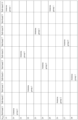
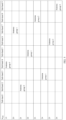
- FIG. 2 is a schematic structural diagram of a sounding reference signal transmission method according to another embodiment of this application. As shown in FIG. 2 , descriptions are provided by using an example in which the quantity ⁇ of antenna groups is 3 and the quantity K of SRS transmission sub-bandwidths included in the frequency hopping bandwidth for the SRS is 10.
- K 10
- the terminal device may measure the entire frequency hopping bandwidth for the SRS once by completing frequency hopping for 10 times.
- the four antenna ports may be grouped into three antenna groups.
- the three antenna groups may include an antenna group 0 (Antenna group 0), an antenna group 1 (Antenna group 1), and an antenna group 2 (Antenna group 2).
- the terminal device may select one antenna group from the antenna group 0, the antenna group 1, and the antenna group 2 according to the antenna selection formula (1) to send the SRS.
- the terminal device may select, from the three antenna groups according to the antenna selection formula (1), an antenna group for sending the SRS.
- the terminal device may choose to send the SRS in an SRS sub-bandwidth 1 (which may also be referred to as a sub-band 1 or a band 1) through antenna ports included in the antenna group 0 (Antenna group 0).
- the terminal device may choose to send the SRS in an SRS sub-bandwidth 6 (which may also be referred to as a sub-band 6 or a band 6) through antenna ports included in the antenna group 1 (Antenna group 1).
- the terminal device may choose to send the SRS in an SRS sub-bandwidth 3 (which may also be referred to as a sub-band 3 or a band 3) through antenna ports included in the antenna group 2 (Antenna group 2).
- an SRS resource may be sequentially sent through the ⁇ antenna groups in ascending order of sequence numbers of the antenna groups.
- the four antenna ports may be grouped into, for example, two antenna groups including an antenna group 0 (Antenna group 0) and an antenna group 1 (Antenna group 1).
- the terminal device may alternatively select either of the antenna group 0 (Antenna group 0) and the antenna group 1 (Antenna group 1) according to the antenna selection formula (1) to send the SRS.
- a selection sequence of the SRS transmission sub-bandwidths included in the frequency hopping bandwidth for the SRS, a total frequency hopping bandwidth for the SRS, and the quantity of SRS transmission sub-bandwidths included in the frequency hopping bandwidth for the SRS are not specifically limited in this embodiment of this application, and may be set based on an SRS configuration parameter.
- the terminal device may select the antenna group whose sequence number is a ( n SRS ) based on the sequence number n SRS of the quantity of transmissions of the SRS and the quantity ⁇ of antenna groups, so that the sequence number a ( n SRS ) of the antenna group for sending the SRS for the n SRS th time is different from a sequence number a ( n SRS + ⁇ ) of an antenna group for sending the SRS for the ( n SRS + ⁇ ) th time.
- the terminal device may select the antenna group whose sequence number is a ( n SRS ) based on the sequence number n SRS of the quantity of transmissions of the SRS and the quantity ⁇ of antenna groups, so that in a process of sending the SRS for K times, a sequence including the sequence number of the antenna group selected for sending the SRS for the n SRS time to the sequence number of the antenna group selected for sending the SRS for the ( n SRS + ⁇ ) time may be a result obtained by performing cyclic shift on a sequence including the sequence number of the antenna group selected for sending the SRS for the ( n SRS + ⁇ ) time to a sequence number of an antenna group selected for sending the SRS for the ( n SRS + 2 ⁇ ) time.
- a sequence including sequence numbers of antenna groups selected by the terminal device may have a cyclic shift feature.
- the sequence including the sequence number of the antenna group selected for sending the SRS for the n SRS time to the sequence number of the antenna group selected for sending the SRS for the ( n SRS + ⁇ ) time may be a result obtained by performing forward cyclic shift on the sequence including the sequence number of the antenna group selected for sending the SRS for the ( n SRS + ⁇ ) time to the sequence number of the antenna group selected for sending the SRS for the ( n SRS + 2 ⁇ ) time.
- the sequence including the sequence number of the antenna group selected for sending the SRS for the n SRS time to the sequence number of the antenna group selected for sending the SRS for the ( n SRS + ⁇ ) time may be a result obtained by performing backward cyclic shift on the sequence including the sequence number of the antenna group selected for sending the SRS for the ( n SRS + ⁇ ) time to the sequence number of the antenna group selected for sending the SRS for the ( n SRS + 2 ⁇ ) time.
- a value of the quantity K of SRS transmission sub-bandwidths included in the frequency hopping bandwidth for the SRS is not specifically limited in this embodiment of this application.
- the terminal device may select one antenna group from the ⁇ antenna groups according to the antenna selection formula (2) to send the SRS.
- a sequence number of one antenna group for sending the SRS is selected from the ⁇ antenna groups according to the antenna selection formula (2), so that the sequence number a ( n SRS ) of the antenna group for sending the SRS for the n SRS th time is different from the sequence number a ( n SRS + ⁇ ) of the antenna group for sending the SRS for the ( n SRS + ⁇ ) th time in this embodiment of this application.
- the example below is merely intended to help a person skilled in the art understand the embodiments of this application, instead of limiting the embodiments of this application to a specific value or a specific scenario in the example. It is clear that a person skilled in the art can make various equivalent modifications or changes based on the example described above, and such modifications and changes also fall within the scope of the embodiments of this application.
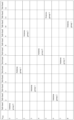
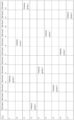
- FIG. 3 is a schematic structural diagram of a sounding reference signal transmission method according to another embodiment of this application.
- the terminal device may select one antenna group from an antenna group 0, an antenna group 1, and an antenna group 2 according to the antenna selection formula (2) to send the SRS.
- the terminal device may select, from the three antenna groups according to the antenna selection formula (2), the antenna group for sending the SRS.
- sequence numbers of antenna groups selected for sending the SRS are sequentially the antenna group 0, the antenna group 1, and the antenna group 2.
- sequence numbers of antenna groups selected for sending the SRS are sequentially the antenna group 1, the antenna group 2, and the antenna group 0.
- sequence numbers of antenna groups selected for sending the SRS are sequentially the antenna group 2, the antenna group 0, and the antenna group 1.
- the terminal device may alternatively select either of the antenna group 0 and the antenna group 1 according to the antenna selection formula (2) to send the SRS, so that the sequence number a ( n SRS ) of the antenna group for sending the SRS for the n SRS th time is different from the sequence number a ( n SRS + ⁇ ) of the antenna group for sending the SRS for the ( n SRS + ⁇ ) th time.
- a relatively large frequency spacing between two adjacent SRS sub-bandwidths occupied for sending the SRS through a same antenna group for example, the antenna group 1.
- SRS sub-bandwidths that are relatively discretely distributed are selected from the frequency hopping bandwidth for the same antenna group to send the SRS, so that channel sounding within a larger bandwidth range can be implemented for a relatively small quantity of SRS transmissions, thereby improving efficiency and accuracy of the channel sounding.
- FIG. 2 and FIG. 3 show that the antenna group for sending the SRS is selected based on the sequence number n SRS of the quantity of transmissions of the SRS and the quantity ⁇ of antenna groups.
- the terminal device may alternatively select, based on the sequence number n SRS of the quantity of transmissions of the SRS, the quantity ⁇ of antenna groups, and the quantity K of SRS transmission sub-bandwidths included in the frequency hopping bandwidth for the SRS, the antenna group for sending the SRS.
- the terminal device may alternatively select, based on the sequence number n SRS of the quantity of transmissions of the SRS, the quantity ⁇ of antenna groups, and the quantity K of SRS transmission sub-bandwidths included in the frequency hopping bandwidth for the SRS, the antenna group for sending the SRS.
- the terminal device may select, based on the sequence number n SRS of the quantity of transmissions of the SRS, the quantity ⁇ of antenna groups, and the quantity K of SRS transmission sub-bandwidths included in the frequency hopping bandwidth for the SRS, the antenna group for sending the SRS, so that in a process of completing measurement of the frequency hopping bandwidth for the SRS (in other words, in a process of sending the SRS for ⁇ K times), the SRS can be sent through each of the ⁇ antenna groups once in any SRS transmission sub-bandwidth included in the frequency hopping bandwidth for the SRS.
- the terminal device may select, based on the sequence number n SRS of the quantity of transmissions of the SRS, the quantity ⁇ of antenna groups, and the quantity K of SRS transmission sub-bandwidths included in the frequency hopping bandwidth for the SRS, the antenna group for sending the SRS, so that in the process of ⁇ K transmissions, a sequence number a ( n SRS + iK ) of an antenna group for sending the SRS for the ( n SRS + iK ) th time is different from a sequence number a ( n SRS + ( i - 1) K ) of an antenna group for sending the SRS for the ( n SRS + ( i - 1) K ) th time and/orthe sequence number a ( n SRS + iK ) of the antenna group for sending the SRS for the ( n SRS + iK ) th time is different from a sequence number a ( n SRS + ( i + 1 K ) of an antenna group for sending the
- the terminal device may select, based on n SRS , ⁇ , and K , the antenna group for sending the SRS, so that in the process of sending the SRS for ⁇ K times, a sequence including sequence numbers of antenna groups selected for sending the SRS for the first K times may be a result obtained by performing cyclic shift on a sequence including sequence numbers of antenna groups selected in a next process of sending the SRS for K times.
- the SRS in the process of sending the SRS for ⁇ K times, can be sent through each of the ⁇ antenna groups once in the K SRS transmission sub-bandwidths included in the frequency hopping bandwidth for the SRS, so that each of the ⁇ antenna groups can be traversed in the K sub-bandwidths, to obtain complete channel information of the K sub-bandwidths that corresponds to all the antenna ports.
- a value of the quantity K of SRS transmission sub-bandwidths included in the frequency hopping bandwidth for the SRS is not specifically limited in this embodiment of this application.
- the quantity K may be any positive integer greater than 0.
- the quantity K may be an integer multiple of the quantity ⁇ of antenna groups.
- the terminal device may select one antenna group from the ⁇ antenna groups according to the antenna selection formula (3) to send the SRS.
- the terminal device may select one antenna group from the ⁇ antenna groups according to the antenna selection formula (3) to send the SRS, so that in the process of completing measurement of the frequency hopping bandwidth for the SRS (in other words, in the process of sending the SRS for ⁇ K times), the SRS can be sent through each of the ⁇ antenna groups once in any SRS transmission sub-bandwidth included in the frequency hopping bandwidth for the SRS.
- a sequence number of one antenna group for sending the SRS may be selected from the ⁇ antenna groups according to the antenna selection formula (3), so that in the process of completing scanning of the frequency hopping bandwidth for the SRS (in other words, in the process of sending the SRS for ⁇ K times), the SRS can be sent through each of the ⁇ antenna groups once in any SRS transmission sub-bandwidth included in the frequency hopping bandwidth for the SRS in this embodiment of this application.
- the example below is merely intended to help a person skilled in the art understand the embodiments of this application, instead of limiting the embodiments of this application to a specific value or a specific scenario in the example. It is clear that a person skilled in the art can make various equivalent modifications or changes based on the example described above, and such modifications and changes also fall within the scope of the embodiments of this application.
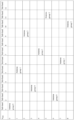
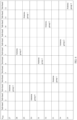
- FIG. 4 is a schematic structural diagram of a sounding reference signal transmission method according to another embodiment of this application.
- the terminal device may select one antenna group from an antenna group 0, an antenna group 1, and an antenna group 2 according to the antenna selection formula (3) to send the SRS.
- an SRS sub-bandwidth 1 (which may also be referred to as a sub-band 1 or a band 1)
- the SRS in the process of sending the SRS for K ⁇ times, can be sent through each of the ⁇ antenna groups once in a same sub-bandwidth (for example, the SRS sub-bandwidth 1). In other words, the SRS can be sent through each of the ⁇ antenna groups once in any SRS transmission sub-bandwidth included in the frequency hopping bandwidth for the SRS.
- a same sub-bandwidth for example, the SRS sub-bandwidth 1
- the SRS can be sent through each of the ⁇ antenna groups once in any SRS transmission sub-bandwidth included in the frequency hopping bandwidth for the SRS.
- the terminal device may alternatively select either of the antenna group 0 and the antenna group 1 according to the antenna selection formula (3) to send the SRS, so that in the process of completing measurement of the frequency hopping bandwidth for the SRS (in other words, in the process of sending the SRS for ⁇ K times), the SRS can be sent through each of the ⁇ antenna groups once in any SRS transmission sub-bandwidth included in the frequency hopping bandwidth for the SRS.
- the terminal device may alternatively select either of the antenna group 0 and the antenna group 1 according to the antenna selection formula (4) to send the SRS.
- a value of the quantity K of SRS transmission sub-bandwidths included in the frequency hopping bandwidth for the SRS is not specifically limited in this embodiment of this application. According to the invention, when K is an integer multiple of the quantity ⁇ of antenna groups, a value of the parameter ⁇ is 1; and when K is an integer multiple of the quantity ⁇ 2 of antenna groups, a value of the parameter ⁇ is 1.
- the sequence number a ( n SRS ) of the antenna group for sending the SRS may be selected from the ⁇ antenna groups according to the antenna selection formula (6), so that in the process of sending the SRS for K ⁇ times, the SRS can be sent through each of the ⁇ antenna groups once in any SRS transmission sub-bandwidth included in the frequency hopping bandwidth for the SRS; and in the process of sending the SRS for the limited quantity of times, for example, for K times, the SRS sub-bandwidths that are relatively discretely distributed can be selected from the frequency hopping bandwidth for the same antenna group to send the SRS, so that the channel sounding within the larger bandwidth range can be implemented for the relatively small quantity of SRS transmissions, thereby improving the efficiency and the accuracy of the channel sounding in this embodiment of this application.
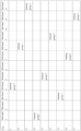
- FIG. 5 is a schematic structural diagram of a sounding reference signal transmission method according to another embodiment of this application.
- the terminal device may select one antenna group from the foregoing three antenna groups according to the antenna selection formula (6) to send the SRS, so that in the process of sending the SRS for K ⁇ times, the SRS can be sent through each of the ⁇ antenna groups in any SRS transmission sub-bandwidth included in the frequency hopping bandwidth for the SRS; and in the process of sending the SRS for the limited quantity of times, for example, for K times, the SRS sub-bandwidths that are relatively discretely distributed can be selected from the frequency hopping bandwidth for the same antenna group to send the SRS, so that the channel sounding within the larger bandwidth range can be implemented for the relatively small quantity of SRS transmissions, thereby improving the efficiency and the accuracy of the channel sounding.
- the terminal device may alternatively select either of the antenna group 0 and the antenna group 1 according to the antenna selection formula (2) to send the SRS, so that in the process of sending the SRS for K ⁇ times, the SRS can be sent through each of the ⁇ antenna groups once in any SRS transmission sub-bandwidth included in the frequency hopping bandwidth for the SRS; and in the process of sending the SRS for the limited quantity of times, for example, for K times, the SRS sub-bandwidths that are relatively discretely distributed can be selected from the frequency hopping bandwidth for the same antenna group to send the SRS, so that the channel sounding within the larger bandwidth range can be implemented for the relatively small quantity of SRS transmissions, thereby improving the efficiency and the accuracy of the channel sounding.
- the SRS in the process of sending the SRS for K ⁇ times, can be sent through each of the ⁇ antenna groups once in any SRS transmission sub-bandwidth included in the frequency hopping bandwidth for the SRS; and in the process of sending the SRS for the limited quantity of times, for example, for K times, the SRS sub-bandwidths that are relatively discretely distributed can be selected from the frequency hopping bandwidth for the same antenna group to send the SRS, so that the channel sounding within the larger bandwidth range can be implemented for the relatively small quantity of SRS transmissions, thereby improving the efficiency and the accuracy of the channel sounding.
- a value of the quantity K of SRS transmission sub-bandwidths included in the frequency hopping bandwidth for the SRS is not specifically limited in this embodiment of this application.
- a value of the parameter ⁇ may be 1; and when K is an integer multiple of the quantity ⁇ of antenna groups, a value of the parameter ⁇ may be 1.
- the sequence number a ( n SRS ) of the antenna group for sending the SRS may be selected from the ⁇ antenna groups according to the antenna selection formula (7), so that in the process of sending the SRS for K ⁇ times, the SRS can be sent through each of the ⁇ antenna groups once in any SRS transmission sub-bandwidth included in the frequency hopping bandwidth for the SRS; and in the process of sending the SRS for the limited quantity of times, for example, for K times, the SRS sub-bandwidths that are relatively discretely distributed can be selected from the frequency hopping bandwidth for the same antenna group to send the SRS, so that the channel sounding within the larger bandwidth range can be implemented for the relatively small quantity of SRS transmissions, thereby improving the efficiency and the accuracy of the channel sounding in this embodiment of this application.
- FIG. 6 is a schematic structural diagram of a sounding reference signal transmission method according to another embodiment of this application.
- the terminal device may select one antenna group from the foregoing three antenna groups according to the antenna selection formula (7) to send the SRS, so that in the process of sending the SRS for K ⁇ times, the SRS can be sent through each of the ⁇ antenna groups in any SRS transmission sub-bandwidth included in the frequency hopping bandwidth for the SRS; and in the process of sending the SRS for the limited quantity of times, for example, for K times, the SRS sub-bandwidths that are relatively discretely distributed can be selected from the frequency hopping bandwidth for the same antenna group to send the SRS, so that the channel sounding within the larger bandwidth range can be implemented for the relatively small quantity of SRS transmissions, thereby improving the efficiency and the accuracy of the channel sounding.
- the terminal device may alternatively select either of the antenna group 0 and the antenna group 1 according to the antenna selection formula (2) to send the SRS, so that in the process of sending the SRS for K ⁇ times, the SRS can be sent through each of the ⁇ antenna groups once in any SRS transmission sub-bandwidth included in the frequency hopping bandwidth for the SRS; and in the process of sending the SRS for the limited quantity of times, for example, for K times, the SRS sub-bandwidths that are relatively discretely distributed can be selected from the frequency hopping bandwidth for the same antenna group to send the SRS, so that the channel sounding within the larger bandwidth range can be implemented for the relatively small quantity of SRS transmissions, thereby improving the efficiency and the accuracy of the channel sounding.
- the SRS in the process of sending the SRS for K ⁇ times, can be sent through each of the ⁇ antenna groups once in any SRS transmission sub-bandwidth included in the frequency hopping bandwidth for the SRS; and in the process of sending the SRS for the limited quantity of times, for example, for K times, the SRS sub-bandwidths that are relatively discretely distributed can be selected from the frequency hopping bandwidth for the same antenna group to send the SRS, so that the channel sounding within the larger bandwidth range can be implemented for the relatively small quantity of SRS transmissions, thereby improving the efficiency and the accuracy of the channel sounding.
- FIG. 7 is a schematic structural diagram of a terminal device according to an embodiment of this application.
- the terminal device 700 in FIG. 7 may perform the sounding reference signal transmission method described in any one of the embodiments in FIG. 1 to FIG. 6 .
- the terminal device 700 in FIG. 7 may include a memory 710, a processor 720, and a transceiver 730.
- the memory 710 may be configured to store a program
- the processor 720 may be configured to execute the program stored in the memory 710.
- the processor 720 may perform, through the transceiver 730, the sounding reference signal transmission method described in any one of the foregoing embodiments.
- a and/or B may represent the following cases: only A exists, both A and B exist, and only B exists.
- the processor may be a central processing unit (central processing unit, CPU), a microprocessor, an application-specific integrated circuit (application-specific integrated circuit, ASIC), one or more integrated circuits for controlling program execution in the solutions of this application, or the like.
- the processor may include a digital signal processor device, a microprocessor device, an analog-to-digital converter, or a digital-to-analog converter.
- the processor may allocate control and signal processing functions of mobile devices between these devices based on respective functions of the devices.
- the processor may include functions for operating one or more software programs, and the software programs may be stored in the memory.
- the memory may be a read-only memory (read-only memory, ROM), another type of static storage device capable of storing static information and instructions, a random access memory (random access memory, RAM), or another type of dynamic storage device capable of storing information and instructions, or may be an electrically erasable programmable read-only memory (electrically erasable programmable read-only memory, EEPROM), a compact disc read-only memory (compact disc read-only memory, CD-ROM) or another compact disc storage, an optical disc storage (including a compact disc, a laser disc, an optical disc, a digital versatile disc, a Blu-ray disc, or the like), a magnetic disk storage medium or another magnetic storage device, or any other medium that can be configured to carry or store expected program code in a form of an instruction or a signal structure and that can be accessed by a computer.
- the memory is not limited thereto.
- the memory may exist alone, or may be integrated into the processor.
- the transceiver may include, for example, an infrared transceiver, an RF transceiver, a wireless universal serial bus (universal serial bus, USB) transceiver, or a Bluetooth transceiver.
- the terminal device and a network device may use a corresponding communications technology to send information (or a signal) through a transmitter, and/or receive information (a signal) through a receiver.
- All or some of the foregoing embodiments may be implemented through software, hardware, firmware, or any combination thereof.
- the embodiments may be implemented completely or partially in a form of a computer program product.
- the computer program product includes one or more computer instructions.
- the computer may be a general-purpose computer, a special-purpose computer, a computer network, or other programmable apparatuses.
- the computer instructions may be stored in a computer-readable storage medium or may be transmitted from a computer-readable storage medium to another computer-readable storage medium.
- the computer instructions may be transmitted from a website, computer, server, or data center to another website, computer, server, or data center in a wired (for example, a coaxial cable, an optical fiber, or a digital subscriber line (digital subscriber line, DSL)) or wireless (for example, infrared, radio, or microwave) manner.
- the computer-readable storage medium may be any usable medium accessible by the computer, or a data storage device, such as a server or a data center, integrating one or more usable media.
- the usable medium may be a magnetic medium (for example, a floppy disk, a hard disk, or a magnetic tape), an optical medium (for example, a digital video disc (digital video disc, DVD)), a semiconductor medium (for example, a solid-state drive (solid state disk, S SD)), or the like.
- a magnetic medium for example, a floppy disk, a hard disk, or a magnetic tape
- an optical medium for example, a digital video disc (digital video disc, DVD)
- a semiconductor medium for example, a solid-state drive (solid state disk, S SD)
- the disclosed system, apparatus, and method may be implemented in other manners.
- the described apparatus embodiment is merely an example.
- the unit division is merely logical function division and may be other division during actual implementation.
- a plurality of units or components may be combined or integrated into another system, or some features may be ignored or not performed.
- the displayed or discussed mutual couplings or direct couplings or communication connections may be implemented via some interfaces.
- the indirect couplings or communication connections between the apparatuses or units may be implemented in electronic, mechanical, or other forms.
- the units described as separate parts may or may not be physically separate, and parts displayed as units may or may not be physical units, may be located in one position, or may be distributed on a plurality of network units. Some or all of the units may be selected based on actual requirements to achieve the objectives of the solutions of the embodiments.
- the functions When the functions are implemented in the form of a software functional unit and sold or used as an independent product, the functions may be stored in a computer-readable storage medium. Based on such an understanding, the technical solutions of this application essentially, or the part contributing to the prior art, or some of the technical solutions may be implemented in a form of a software product.
- the computer software product is stored in a storage medium, and includes several instructions for instructing a computer device (which may be a personal computer, a server, a network device, or the like) to perform all or some of the steps of the methods described in the embodiments of this application.
- the foregoing storage medium includes: any medium that can store program code, such as a USB flash drive, a removable hard disk, a read-only memory (read-only memory, ROM), a random access memory (random access memory, RAM), a magnetic disk, or an optical disc.
- program code such as a USB flash drive, a removable hard disk, a read-only memory (read-only memory, ROM), a random access memory (random access memory, RAM), a magnetic disk, or an optical disc.
Landscapes
- Engineering & Computer Science (AREA)
- Signal Processing (AREA)
- Computer Networks & Wireless Communication (AREA)
- Mobile Radio Communication Systems (AREA)
Claims (7)
- Verfahren zur Übertragung eines Sounding-Referenzsignals, Folgendes umfassend:Auswählen (110), auf der Grundlage einer Sequenznummer nSRS einer Quantität von Übertragungen eines Sounding-Referenzsignals, SRS, und einer Quantität A von Antennengruppen, einer Antennengruppe, deren Sequenznummer a(nSRS ) ist, aus den A Antennengruppen, so dass in einem Prozess zum 2A-fachen Senden des SRS, das SRS durch jede der A Antennengruppen mindestens einmal gesendet wird, wobei nSRS eine ganze Zahl größer oder gleich 0 ist und A eine positive ganze Zahl größer oder gleich 3 ist; undSenden (120), während der nSRS-ten SRS-Übertragung, des SRS durch Antennenports, die in der Antennengruppe enthalten sind, deren Sequenznummer α(nSRS) ist;dadurch gekennzeichnet, dassdas Auswählen (110), auf der Grundlage einer Sequenznummer nSRS einer Quantität von Übertragungen eines Sounding-Referenzsignals SRS und einer Quantität A von Antennengruppen, einer Antennengruppe, deren Sequenznummer α(nSRS) ist, aus den A Antennengruppen Folgendes umfasst:Bestimmen, gemäß der folgenden Formel, der Sequenznummer α(nSRS) der Antennengruppe zum Senden (120) des SRS:

 wobei K die Anzahl von SRS-Übertragungsunterbandbreiten ist, die in einer Frequenzsprungbandbreite für das SRS enthalten sind, und wobei K eine positive ganze Zahl größer als 0 ist,und
 (nSRS + α[nSRS / A] + β[nSRS / K]) mod A verwendet wird, um einen Rest zu repräsentieren, der erhalten wird durch Dividieren von (nSRS + α[nSRS / A] + β[nSRS / K]) durch A.
 - Verfahren nach Anspruch 1, wobei das Auswählen (110), auf der Grundlage einer Sequenznummer nSRS einer Quantität von Übertragungen eines Sounding-Referenzsignals SRS und einer Quantität A von Antennengruppen, einer Antennengruppe, deren Sequenznummer α(nSRS) ist, aus den A Antennengruppen Folgendes umfasst:
Auswählen (110) der Antennengruppe, deren Sequenznummer α(nSRS) ist, aus den A Antennengruppen auf der Grundlage der Sequenznummer nSRS der Quantität von Übertragungen des SRS, der Quantität A der Antennengruppen und der Quantität K der SRS-Übertragungsunterbandbreiten, die in einer Frequenzsprungbandbreite für das SRS enthalten sind, so dass eine Sequenznummer a(nSRS + iK) einer Antennengruppe zum Senden (120) des SRS zum (nSRS + iK)-ten Mal verschieden ist von einer Sequenznummer a(nSRS + (i - 1)K) einer Antennengruppe zum Senden (120) des SRS zum (nSRS + (i - 1)K)-ten Mal und/oder die Sequenznummer α(nSRS + iK) der Antennengruppe zum Senden (120) des SRS zum (nSRS + iK)-ten Mal verschieden ist von einer Sequenznummer α(nSRS + (i + i)K) einer Antennengruppe zum Senden (120) des SRS zum (nSRS + (i + 1)K)-ten Mal, wobei 1 ≤ i ≤ (Λ - 2). - Verfahren nach Anspruch 1, wobei das Auswählen (110), auf der Grundlage einer Sequenznummer nSRS einer Quantität von Übertragungen eines Sounding-Referenzsignals SRS und einer Quantität A von Antennengruppen, einer Antennengruppe, deren Sequenznummer α(nSRS) ist, aus den A Antennengruppen Folgendes umfasst:
Auswählen (110) der Antennengruppe, deren Sequenznummer α(nSRS) ist, aus den A Antennengruppen auf der Grundlage der Sequenznummer nSRS der Quantität von Übertragungen des SRS und der Quantität A von Antennengruppen, so dass die Sequenznummer α(nSRS) der Antennengruppe zum Senden (120) des SRS zum nSRS-ten Mal verschieden ist von einer Sequenznummer α(nSRS + A) einer Antennengruppe zum Senden (120) des SRS zum (nSRS + A)-ten Mal. - Verfahren nach einem der Ansprüche 1 bis 3, wobei jede der A Antennengruppen mindestens zwei verschiedene Antennenports umfasst und die A Antennengruppen alle Antennenports eines Endgeräts (700) umfassen.
- Endgerät (700), einen Speicher (710), einen Prozessor (720) und einen Sendeempfänger (730) umfassend, wobeider Speicher (710) konfiguriert ist, ein Programm zu speichern; undder Prozessor (720) konfiguriert ist, das Programm auszuführen, das im Speicher (710) gespeichert ist, und, wenn das Programm ausgeführt wird, der Prozessor (720) das Verfahren nach einem der Ansprüche 1 bis 4 durch den Sendeempfänger (730) durchführt.
- Chip, einen Speicher (710), einen Prozessor (720) und einen Sendeempfänger (730) umfassend, wobei der Speicher (710) konfiguriert ist, ein Programm zu speichern; und
der Prozessor (720) konfiguriert ist, das Programm auszuführen, das im Speicher (710) gespeichert ist, und, wenn das Programm ausgeführt wird, der Prozessor (720) das Verfahren nach einem der Ansprüche 1 bis 4 durch den Sendeempfänger durchführt. - Computerlesbares Speichermedium, einen Computerbefehl umfassend, wobei, wenn der Computerbefehl auf einem Endgerät (700) abläuft, dem Endgerät (700) ermöglicht wird, das Verfahren nach einem der Ansprüche 1 bis 4 durchzuführen.
Applications Claiming Priority (1)
| Application Number | Priority Date | Filing Date | Title |
|---|---|---|---|
| PCT/CN2018/081804 WO2019191915A1 (zh) | 2018-04-04 | 2018-04-04 | 传输探测参考信号的方法、终端设备及计算机可读存储介质 |
Publications (3)
| Publication Number | Publication Date |
|---|---|
| EP3764561A1 EP3764561A1 (de) | 2021-01-13 |
| EP3764561A4 EP3764561A4 (de) | 2021-01-27 |
| EP3764561B1 true EP3764561B1 (de) | 2023-08-16 |
Family
ID=68099796
Family Applications (1)
| Application Number | Title | Priority Date | Filing Date |
|---|---|---|---|
| EP18913470.3A Active EP3764561B1 (de) | 2018-04-04 | 2018-04-04 | Verfahren zur übertragung eines sounding-referenzsignals, endgerät und computerlesbares speichermedium |
Country Status (5)
| Country | Link |
|---|---|
| US (1) | US11265062B2 (de) |
| EP (1) | EP3764561B1 (de) |
| JP (1) | JP7136916B2 (de) |
| CN (1) | CN111886810B (de) |
| WO (1) | WO2019191915A1 (de) |
Families Citing this family (3)
| Publication number | Priority date | Publication date | Assignee | Title |
|---|---|---|---|---|
| CN113839758B (zh) * | 2020-06-24 | 2022-11-04 | 大唐移动通信设备有限公司 | 一种载波相位定位参考信号的传输方法及装置 |
| WO2022217524A1 (en) * | 2021-04-15 | 2022-10-20 | Qualcomm Incorporated | Signaling user equipment antenna group preferences and antenna group correlation |
| CN118316484B (zh) * | 2024-03-29 | 2025-02-28 | 荣耀终端股份有限公司 | 通信方法、设备及存储介质 |
Citations (1)
| Publication number | Priority date | Publication date | Assignee | Title |
|---|---|---|---|---|
| EP2297980B1 (de) * | 2008-06-24 | 2018-08-29 | Mitsubishi Electric Corporation | Antennenauswahl mit klangreferenzsignalen mit wechselnder frequenz |
Family Cites Families (8)
| Publication number | Priority date | Publication date | Assignee | Title |
|---|---|---|---|---|
| KR101639810B1 (ko) | 2009-01-13 | 2016-07-25 | 엘지전자 주식회사 | 무선통신 시스템에서 사운딩 참조신호의 전송방법 |
| US8824584B2 (en) * | 2009-02-24 | 2014-09-02 | Lg Electronics Inc. | Method for transmitting sounding reference signal in MIMO wireless communication system and apparatus therefor |
| CN102223167B (zh) | 2010-04-16 | 2015-11-25 | 华为技术有限公司 | 多天线系统中的探测参考信号发送方法及装置 |
| CN102355293B (zh) * | 2011-08-15 | 2017-02-08 | 中兴通讯股份有限公司 | 测量参考信号发射方法及装置 |
| CN103905104B (zh) * | 2012-12-28 | 2017-12-19 | 中兴通讯股份有限公司 | 一种根据探测参考信号的多天线发送方法及终端及基站 |
| CN106559277A (zh) * | 2015-09-25 | 2017-04-05 | 中兴通讯股份有限公司 | 探测参考信号的发送方法及装置、信令配置方法及装置 |
| US11558161B2 (en) * | 2017-07-27 | 2023-01-17 | Lg Electronics Inc. | Method for transmitting SRS and terminal therefor |
| US10938529B2 (en) * | 2018-02-14 | 2021-03-02 | Qualcomm Incorporated | Sounding reference signal antenna switching in scheduled entities having at least four antennas |
-
2018
- 2018-04-04 CN CN201880091566.6A patent/CN111886810B/zh active Active
- 2018-04-04 JP JP2020554253A patent/JP7136916B2/ja active Active
- 2018-04-04 WO PCT/CN2018/081804 patent/WO2019191915A1/zh not_active Ceased
- 2018-04-04 EP EP18913470.3A patent/EP3764561B1/de active Active
-
2020
- 2020-10-02 US US17/062,139 patent/US11265062B2/en active Active
Patent Citations (1)
| Publication number | Priority date | Publication date | Assignee | Title |
|---|---|---|---|---|
| EP2297980B1 (de) * | 2008-06-24 | 2018-08-29 | Mitsubishi Electric Corporation | Antennenauswahl mit klangreferenzsignalen mit wechselnder frequenz |
Also Published As
| Publication number | Publication date |
|---|---|
| WO2019191915A1 (zh) | 2019-10-10 |
| EP3764561A4 (de) | 2021-01-27 |
| US11265062B2 (en) | 2022-03-01 |
| JP2021520132A (ja) | 2021-08-12 |
| JP7136916B2 (ja) | 2022-09-13 |
| EP3764561A1 (de) | 2021-01-13 |
| CN111886810B (zh) | 2021-12-24 |
| CN111886810A (zh) | 2020-11-03 |
| US20210021319A1 (en) | 2021-01-21 |
Similar Documents
| Publication | Publication Date | Title |
|---|---|---|
| JP7381622B2 (ja) | 無線通信方法及び装置 | |
| CN109587679B (zh) | 信息传输的方法、终端设备和网络设备 | |
| US11165607B2 (en) | Method for transmitting sounding reference signal, terminal device and network device | |
| US12574950B2 (en) | Method for configuring resources for physical downlink control channel transmission, terminal device and network device | |
| AU2017391788B2 (en) | Method for transmitting data, terminal device and network device | |
| CN109565840A (zh) | 探测参考信号传输方法、终端设备和网络设备 | |
| AU2016428454B2 (en) | Communication method, terminal, and network device | |
| CN113316122A (zh) | 侧行通信的方法和终端设备 | |
| JP6971321B2 (ja) | 送信方法、ネットワークデバイス、及び端末デバイス | |
| CN110786038B (zh) | 数据传输的方法、终端设备和网络设备 | |
| US11652670B2 (en) | Method for transmitting sounding reference signal and terminal device | |
| US11265062B2 (en) | Sounding reference signal transmission method, terminal device, and computer-readable storage medium | |
| WO2018228533A1 (zh) | 资源映射的方法和装置 | |
| US11711823B2 (en) | Wireless communication method, network device, and terminal device | |
| CN110870361A (zh) | 无线通信方法和设备 | |
| US12120642B2 (en) | Method for demodulating shared reference signal, terminal device, and network device | |
| JP2020522941A (ja) | 信号伝送方法、端末デバイスおよびネットワークデバイス | |
| EP3579630A1 (de) | Verfahren und system zur übertragung von downlink-steuerungsinformationen | |
| EP3764711B1 (de) | Verfahren und vorrichtung für ressourcenzuweisung |
Legal Events
| Date | Code | Title | Description |
|---|---|---|---|
| STAA | Information on the status of an ep patent application or granted ep patent |
Free format text: STATUS: THE INTERNATIONAL PUBLICATION HAS BEEN MADE |
|
| PUAI | Public reference made under article 153(3) epc to a published international application that has entered the european phase |
Free format text: ORIGINAL CODE: 0009012 |
|
| STAA | Information on the status of an ep patent application or granted ep patent |
Free format text: STATUS: REQUEST FOR EXAMINATION WAS MADE |
|
| 17P | Request for examination filed |
Effective date: 20201007 |
|
| AK | Designated contracting states |
Kind code of ref document: A1 Designated state(s): AL AT BE BG CH CY CZ DE DK EE ES FI FR GB GR HR HU IE IS IT LI LT LU LV MC MK MT NL NO PL PT RO RS SE SI SK SM TR |
|
| AX | Request for extension of the european patent |
Extension state: BA ME |
|
| A4 | Supplementary search report drawn up and despatched |
Effective date: 20210112 |
|
| RIC1 | Information provided on ipc code assigned before grant |
Ipc: H04B 7/0413 20170101ALI20201221BHEP Ipc: H04B 7/0456 20170101ALI20201221BHEP Ipc: H04L 12/26 20060101ALI20201221BHEP Ipc: H04B 7/06 20060101AFI20201221BHEP |
|
| DAV | Request for validation of the european patent (deleted) | ||
| DAX | Request for extension of the european patent (deleted) | ||
| GRAP | Despatch of communication of intention to grant a patent |
Free format text: ORIGINAL CODE: EPIDOSNIGR1 |
|
| STAA | Information on the status of an ep patent application or granted ep patent |
Free format text: STATUS: GRANT OF PATENT IS INTENDED |
|
| RIC1 | Information provided on ipc code assigned before grant |
Ipc: H04B 7/0456 20170101ALI20230222BHEP Ipc: H04B 7/0413 20170101ALI20230222BHEP Ipc: H04B 7/06 20060101AFI20230222BHEP |
|
| INTG | Intention to grant announced |
Effective date: 20230321 |
|
| GRAS | Grant fee paid |
Free format text: ORIGINAL CODE: EPIDOSNIGR3 |
|
| GRAA | (expected) grant |
Free format text: ORIGINAL CODE: 0009210 |
|
| STAA | Information on the status of an ep patent application or granted ep patent |
Free format text: STATUS: THE PATENT HAS BEEN GRANTED |
|
| AK | Designated contracting states |
Kind code of ref document: B1 Designated state(s): AL AT BE BG CH CY CZ DE DK EE ES FI FR GB GR HR HU IE IS IT LI LT LU LV MC MK MT NL NO PL PT RO RS SE SI SK SM TR |
|
| REG | Reference to a national code |
Ref country code: CH Ref legal event code: EP |
|
| REG | Reference to a national code |
Ref country code: DE Ref legal event code: R096 Ref document number: 602018055722 Country of ref document: DE |
|
| REG | Reference to a national code |
Ref country code: IE Ref legal event code: FG4D |
|
| REG | Reference to a national code |
Ref country code: LT Ref legal event code: MG9D |
|
| REG | Reference to a national code |
Ref country code: NL Ref legal event code: MP Effective date: 20230816 |
|
| REG | Reference to a national code |
Ref country code: AT Ref legal event code: MK05 Ref document number: 1601066 Country of ref document: AT Kind code of ref document: T Effective date: 20230816 |
|
| PG25 | Lapsed in a contracting state [announced via postgrant information from national office to epo] |
Ref country code: GR Free format text: LAPSE BECAUSE OF FAILURE TO SUBMIT A TRANSLATION OF THE DESCRIPTION OR TO PAY THE FEE WITHIN THE PRESCRIBED TIME-LIMIT Effective date: 20231117 |
|
| PG25 | Lapsed in a contracting state [announced via postgrant information from national office to epo] |
Ref country code: IS Free format text: LAPSE BECAUSE OF FAILURE TO SUBMIT A TRANSLATION OF THE DESCRIPTION OR TO PAY THE FEE WITHIN THE PRESCRIBED TIME-LIMIT Effective date: 20231216 |
|
| PG25 | Lapsed in a contracting state [announced via postgrant information from national office to epo] |
Ref country code: SE Free format text: LAPSE BECAUSE OF FAILURE TO SUBMIT A TRANSLATION OF THE DESCRIPTION OR TO PAY THE FEE WITHIN THE PRESCRIBED TIME-LIMIT Effective date: 20230816 Ref country code: RS Free format text: LAPSE BECAUSE OF FAILURE TO SUBMIT A TRANSLATION OF THE DESCRIPTION OR TO PAY THE FEE WITHIN THE PRESCRIBED TIME-LIMIT Effective date: 20230816 Ref country code: PT Free format text: LAPSE BECAUSE OF FAILURE TO SUBMIT A TRANSLATION OF THE DESCRIPTION OR TO PAY THE FEE WITHIN THE PRESCRIBED TIME-LIMIT Effective date: 20231218 Ref country code: NO Free format text: LAPSE BECAUSE OF FAILURE TO SUBMIT A TRANSLATION OF THE DESCRIPTION OR TO PAY THE FEE WITHIN THE PRESCRIBED TIME-LIMIT Effective date: 20231116 Ref country code: NL Free format text: LAPSE BECAUSE OF FAILURE TO SUBMIT A TRANSLATION OF THE DESCRIPTION OR TO PAY THE FEE WITHIN THE PRESCRIBED TIME-LIMIT Effective date: 20230816 Ref country code: LV Free format text: LAPSE BECAUSE OF FAILURE TO SUBMIT A TRANSLATION OF THE DESCRIPTION OR TO PAY THE FEE WITHIN THE PRESCRIBED TIME-LIMIT Effective date: 20230816 Ref country code: LT Free format text: LAPSE BECAUSE OF FAILURE TO SUBMIT A TRANSLATION OF THE DESCRIPTION OR TO PAY THE FEE WITHIN THE PRESCRIBED TIME-LIMIT Effective date: 20230816 Ref country code: IS Free format text: LAPSE BECAUSE OF FAILURE TO SUBMIT A TRANSLATION OF THE DESCRIPTION OR TO PAY THE FEE WITHIN THE PRESCRIBED TIME-LIMIT Effective date: 20231216 Ref country code: HR Free format text: LAPSE BECAUSE OF FAILURE TO SUBMIT A TRANSLATION OF THE DESCRIPTION OR TO PAY THE FEE WITHIN THE PRESCRIBED TIME-LIMIT Effective date: 20230816 Ref country code: GR Free format text: LAPSE BECAUSE OF FAILURE TO SUBMIT A TRANSLATION OF THE DESCRIPTION OR TO PAY THE FEE WITHIN THE PRESCRIBED TIME-LIMIT Effective date: 20231117 Ref country code: FI Free format text: LAPSE BECAUSE OF FAILURE TO SUBMIT A TRANSLATION OF THE DESCRIPTION OR TO PAY THE FEE WITHIN THE PRESCRIBED TIME-LIMIT Effective date: 20230816 Ref country code: AT Free format text: LAPSE BECAUSE OF FAILURE TO SUBMIT A TRANSLATION OF THE DESCRIPTION OR TO PAY THE FEE WITHIN THE PRESCRIBED TIME-LIMIT Effective date: 20230816 |
|
| PG25 | Lapsed in a contracting state [announced via postgrant information from national office to epo] |
Ref country code: PL Free format text: LAPSE BECAUSE OF FAILURE TO SUBMIT A TRANSLATION OF THE DESCRIPTION OR TO PAY THE FEE WITHIN THE PRESCRIBED TIME-LIMIT Effective date: 20230816 |
|
| PG25 | Lapsed in a contracting state [announced via postgrant information from national office to epo] |
Ref country code: ES Free format text: LAPSE BECAUSE OF FAILURE TO SUBMIT A TRANSLATION OF THE DESCRIPTION OR TO PAY THE FEE WITHIN THE PRESCRIBED TIME-LIMIT Effective date: 20230816 |
|
| PG25 | Lapsed in a contracting state [announced via postgrant information from national office to epo] |
Ref country code: SM Free format text: LAPSE BECAUSE OF FAILURE TO SUBMIT A TRANSLATION OF THE DESCRIPTION OR TO PAY THE FEE WITHIN THE PRESCRIBED TIME-LIMIT Effective date: 20230816 Ref country code: RO Free format text: LAPSE BECAUSE OF FAILURE TO SUBMIT A TRANSLATION OF THE DESCRIPTION OR TO PAY THE FEE WITHIN THE PRESCRIBED TIME-LIMIT Effective date: 20230816 Ref country code: ES Free format text: LAPSE BECAUSE OF FAILURE TO SUBMIT A TRANSLATION OF THE DESCRIPTION OR TO PAY THE FEE WITHIN THE PRESCRIBED TIME-LIMIT Effective date: 20230816 Ref country code: EE Free format text: LAPSE BECAUSE OF FAILURE TO SUBMIT A TRANSLATION OF THE DESCRIPTION OR TO PAY THE FEE WITHIN THE PRESCRIBED TIME-LIMIT Effective date: 20230816 Ref country code: DK Free format text: LAPSE BECAUSE OF FAILURE TO SUBMIT A TRANSLATION OF THE DESCRIPTION OR TO PAY THE FEE WITHIN THE PRESCRIBED TIME-LIMIT Effective date: 20230816 Ref country code: CZ Free format text: LAPSE BECAUSE OF FAILURE TO SUBMIT A TRANSLATION OF THE DESCRIPTION OR TO PAY THE FEE WITHIN THE PRESCRIBED TIME-LIMIT Effective date: 20230816 Ref country code: SK Free format text: LAPSE BECAUSE OF FAILURE TO SUBMIT A TRANSLATION OF THE DESCRIPTION OR TO PAY THE FEE WITHIN THE PRESCRIBED TIME-LIMIT Effective date: 20230816 |
|
| REG | Reference to a national code |
Ref country code: DE Ref legal event code: R097 Ref document number: 602018055722 Country of ref document: DE |
|
| PLBE | No opposition filed within time limit |
Free format text: ORIGINAL CODE: 0009261 |
|
| STAA | Information on the status of an ep patent application or granted ep patent |
Free format text: STATUS: NO OPPOSITION FILED WITHIN TIME LIMIT |
|
| REG | Reference to a national code |
Ref country code: GB Ref legal event code: 732E Free format text: REGISTERED BETWEEN 20240530 AND 20240605 |
|
| 26N | No opposition filed |
Effective date: 20240517 |
|
| REG | Reference to a national code |
Ref country code: DE Ref legal event code: R081 Ref document number: 602018055722 Country of ref document: DE Owner name: GODO KAISHA IP BRIDGE 1, JP Free format text: FORMER OWNER: HUAWEI TECHNOLOGIES CO., LTD., SHENZHEN, GUANGDONG, CN |
|
| PG25 | Lapsed in a contracting state [announced via postgrant information from national office to epo] |
Ref country code: IT Free format text: LAPSE BECAUSE OF FAILURE TO SUBMIT A TRANSLATION OF THE DESCRIPTION OR TO PAY THE FEE WITHIN THE PRESCRIBED TIME-LIMIT Effective date: 20230816 Ref country code: SI Free format text: LAPSE BECAUSE OF FAILURE TO SUBMIT A TRANSLATION OF THE DESCRIPTION OR TO PAY THE FEE WITHIN THE PRESCRIBED TIME-LIMIT Effective date: 20230816 |
|
| PG25 | Lapsed in a contracting state [announced via postgrant information from national office to epo] |
Ref country code: BG Free format text: LAPSE BECAUSE OF FAILURE TO SUBMIT A TRANSLATION OF THE DESCRIPTION OR TO PAY THE FEE WITHIN THE PRESCRIBED TIME-LIMIT Effective date: 20230816 |
|
| PG25 | Lapsed in a contracting state [announced via postgrant information from national office to epo] |
Ref country code: MC Free format text: LAPSE BECAUSE OF FAILURE TO SUBMIT A TRANSLATION OF THE DESCRIPTION OR TO PAY THE FEE WITHIN THE PRESCRIBED TIME-LIMIT Effective date: 20230816 |
|
| PG25 | Lapsed in a contracting state [announced via postgrant information from national office to epo] |
Ref country code: MC Free format text: LAPSE BECAUSE OF FAILURE TO SUBMIT A TRANSLATION OF THE DESCRIPTION OR TO PAY THE FEE WITHIN THE PRESCRIBED TIME-LIMIT Effective date: 20230816 Ref country code: BG Free format text: LAPSE BECAUSE OF FAILURE TO SUBMIT A TRANSLATION OF THE DESCRIPTION OR TO PAY THE FEE WITHIN THE PRESCRIBED TIME-LIMIT Effective date: 20230816 |
|
| REG | Reference to a national code |
Ref country code: CH Ref legal event code: PL |
|
| PG25 | Lapsed in a contracting state [announced via postgrant information from national office to epo] |
Ref country code: LU Free format text: LAPSE BECAUSE OF NON-PAYMENT OF DUE FEES Effective date: 20240404 |
|
| REG | Reference to a national code |
Ref country code: BE Ref legal event code: MM Effective date: 20240430 |
|
| PG25 | Lapsed in a contracting state [announced via postgrant information from national office to epo] |
Ref country code: LU Free format text: LAPSE BECAUSE OF NON-PAYMENT OF DUE FEES Effective date: 20240404 |
|
| PG25 | Lapsed in a contracting state [announced via postgrant information from national office to epo] |
Ref country code: BE Free format text: LAPSE BECAUSE OF NON-PAYMENT OF DUE FEES Effective date: 20240430 |
|
| PG25 | Lapsed in a contracting state [announced via postgrant information from national office to epo] |
Ref country code: FR Free format text: LAPSE BECAUSE OF NON-PAYMENT OF DUE FEES Effective date: 20240430 |
|
| PG25 | Lapsed in a contracting state [announced via postgrant information from national office to epo] |
Ref country code: FR Free format text: LAPSE BECAUSE OF NON-PAYMENT OF DUE FEES Effective date: 20240430 Ref country code: BE Free format text: LAPSE BECAUSE OF NON-PAYMENT OF DUE FEES Effective date: 20240430 Ref country code: CH Free format text: LAPSE BECAUSE OF NON-PAYMENT OF DUE FEES Effective date: 20240430 |
|
| PG25 | Lapsed in a contracting state [announced via postgrant information from national office to epo] |
Ref country code: IE Free format text: LAPSE BECAUSE OF NON-PAYMENT OF DUE FEES Effective date: 20240404 |
|
| PGFP | Annual fee paid to national office [announced via postgrant information from national office to epo] |
Ref country code: DE Payment date: 20250422 Year of fee payment: 8 |
|
| PGFP | Annual fee paid to national office [announced via postgrant information from national office to epo] |
Ref country code: GB Payment date: 20250423 Year of fee payment: 8 |
|
| PG25 | Lapsed in a contracting state [announced via postgrant information from national office to epo] |
Ref country code: CY Free format text: LAPSE BECAUSE OF FAILURE TO SUBMIT A TRANSLATION OF THE DESCRIPTION OR TO PAY THE FEE WITHIN THE PRESCRIBED TIME-LIMIT; INVALID AB INITIO Effective date: 20180404 |
|
| PG25 | Lapsed in a contracting state [announced via postgrant information from national office to epo] |
Ref country code: HU Free format text: LAPSE BECAUSE OF FAILURE TO SUBMIT A TRANSLATION OF THE DESCRIPTION OR TO PAY THE FEE WITHIN THE PRESCRIBED TIME-LIMIT; INVALID AB INITIO Effective date: 20180404 |
|
| PG25 | Lapsed in a contracting state [announced via postgrant information from national office to epo] |
Ref country code: TR Free format text: LAPSE BECAUSE OF FAILURE TO SUBMIT A TRANSLATION OF THE DESCRIPTION OR TO PAY THE FEE WITHIN THE PRESCRIBED TIME-LIMIT Effective date: 20230816 |