EP3764744A1 - Dispositif d'éclairage - Google Patents
Dispositif d'éclairage Download PDFInfo
- Publication number
- EP3764744A1 EP3764744A1 EP19763303.5A EP19763303A EP3764744A1 EP 3764744 A1 EP3764744 A1 EP 3764744A1 EP 19763303 A EP19763303 A EP 19763303A EP 3764744 A1 EP3764744 A1 EP 3764744A1
- Authority
- EP
- European Patent Office
- Prior art keywords
- light source
- vehicle
- power supply
- cabin
- electric power
- Prior art date
- Legal status (The legal status is an assumption and is not a legal conclusion. Google has not performed a legal analysis and makes no representation as to the accuracy of the status listed.)
- Granted
Links
Images


Classifications
-
- B—PERFORMING OPERATIONS; TRANSPORTING
- B60—VEHICLES IN GENERAL
- B60Q—ARRANGEMENT OF SIGNALLING OR LIGHTING DEVICES, THE MOUNTING OR SUPPORTING THEREOF OR CIRCUITS THEREFOR, FOR VEHICLES IN GENERAL
- B60Q3/00—Arrangement of lighting devices for vehicle interiors; Lighting devices specially adapted for vehicle interiors
- B60Q3/40—Arrangement of lighting devices for vehicle interiors; Lighting devices specially adapted for vehicle interiors specially adapted for specific vehicle types
- B60Q3/41—Arrangement of lighting devices for vehicle interiors; Lighting devices specially adapted for vehicle interiors specially adapted for specific vehicle types for mass transit vehicles, e.g. buses
- B60Q3/47—Circuits; Control arrangements
-
- B—PERFORMING OPERATIONS; TRANSPORTING
- B60—VEHICLES IN GENERAL
- B60Q—ARRANGEMENT OF SIGNALLING OR LIGHTING DEVICES, THE MOUNTING OR SUPPORTING THEREOF OR CIRCUITS THEREFOR, FOR VEHICLES IN GENERAL
- B60Q3/00—Arrangement of lighting devices for vehicle interiors; Lighting devices specially adapted for vehicle interiors
- B60Q3/40—Arrangement of lighting devices for vehicle interiors; Lighting devices specially adapted for vehicle interiors specially adapted for specific vehicle types
- B60Q3/41—Arrangement of lighting devices for vehicle interiors; Lighting devices specially adapted for vehicle interiors specially adapted for specific vehicle types for mass transit vehicles, e.g. buses
- B60Q3/43—General lighting
-
- B—PERFORMING OPERATIONS; TRANSPORTING
- B61—RAILWAYS
- B61D—BODY DETAILS OR KINDS OF RAILWAY VEHICLES
- B61D29/00—Lighting
-
- H—ELECTRICITY
- H05—ELECTRIC TECHNIQUES NOT OTHERWISE PROVIDED FOR
- H05B—ELECTRIC HEATING; ELECTRIC LIGHT SOURCES NOT OTHERWISE PROVIDED FOR; CIRCUIT ARRANGEMENTS FOR ELECTRIC LIGHT SOURCES, IN GENERAL
- H05B47/00—Circuit arrangements for operating light sources in general, i.e. where the type of light source is not relevant
- H05B47/10—Controlling the light source
- H05B47/17—Operational modes, e.g. switching from manual to automatic mode or prohibiting specific operations
Definitions
- the present invention relates to a lighting device that is loaded in a vehicle for illuminating the inside of a cabin thereof, and particularly to the same that is applied to a railroad vehicle.
- the conventional lighting device for use in a railroad vehicle as a plurality of indoor lamps for illuminating the inside of a cabin thereof, there has been provided a standby lamp that is lighted up with a drive circuit being switched over to an on-vehicle battery, in addition to a general lamp that is turned off in an emergency in which power fed to the vehicle is cut off.
- the standby lamp plays a role for clearly indicating the evacuation route.
- the standby lamp is generally installed in the vicinity of a door, and as shown in Figure 4(b) , in a limited express train, such as the Shinkansen line, it is installed only in the vicinity of a cabin entrance at a vehicle end. Therefore, as shown in Figure 5(a) , in an emergency with a limited express train, the area in the vicinity of the vehicle end is bright, while, the areas other than that are dark, thus the difference in illuminance between the location where a standby lamp is provided and that where it is not provided is large, the passengers in the dark area being not capable of looking their feet at the time of evacuation, thereby the conventional lighting device having had room for improvement of the safety thereof.
- a limited express train such as the Shinkansen line
- the applicant of the present invention has already proposed a system that comprises at least one battery for each two indoor lamps (a general lamp and a standby lamp) in the different electrical systems, and that, in an emergency, driving of all the indoor lamps is switched over to that from the respective batteries.
- a system that comprises at least one battery for each two indoor lamps (a general lamp and a standby lamp) in the different electrical systems, and that, in an emergency, driving of all the indoor lamps is switched over to that from the respective batteries.
- Patent Document 1 With such a system, by increasing the brightness of the cabin in an emergency, the sense of insecurity of the passengers can be reduced.
- Patent Document 1 Japanese Unexamined Patent Application Publication No. 2016-203879
- each one indoor lamp in the two electrical systems is separately provided with a battery, and an extra wiring for connecting the respective batteries is needed. Therefore, the wiring space in the spatially limited cabin is increased, resulting in the possibility of causing an increase in weight and cost, thereby a further measure for improvement having been demanded.
- the present invention has been made in view of the above-mentioned problems that are associated with the conventional technology, and is intended to provide a lighting device that is capable of easily securing the required brightness throughout the vehicle in an emergency with a simple and convenient configuration, and is capable of further improving the safety at the time of evacuation with no need for increasing the cost.
- the lighting fixture is provided in order to wholly irradiate the inside of the cabin over the longitudinal direction of the vehicle.
- the lighting fixture includes the first light source and the second light source, which is lighted at an illuminance lower than that at which the first light source is lighted, and the irradiation from each light source is executed in order to wholly illuminate the inside of the cabin over the longitudinal direction of the vehicle as with that from a conventional general lamp, rather than to locally illuminate the inside of the cabin as with that from a conventional standby lamp.
- the first light source is supplied with electric power from the power supply not through the storage battery, while the second light source being supplied with electric power from the power supply through the storage battery.
- the circuit and wiring for such lighting fixture in an emergency, when the power fed from the power supply is shut off, the supply of electric power to the first light source is interrupted, the first light source being extinguished.
- the second light source is supplied with electric power from the battery, thereby the second light source being continued to be lighted at a low illuminance without being extinguished.
- the second light source can be continued to be lighted without performing a special switching operation or control.
- the second light source functions as a standby lamp to wholly irradiate the inside of the cabin over the longitudinal direction of the vehicle, whereby the passengers can safely evacuate if they are in any location in the inside of the cabin.
- the second light source is specified to be one, being lighted at a low illuminance also at the normal time, and of a type, consuming less power, compared to the first light source, thus the lighting thereof can be maintained over a period of time as long as possible within the predetermined range of capacity of the battery.
- the parts of the wirings just ahead of the AC-DC conversion circuit can be unified into one for common use. Since the first light source and the second light source are included in the same lighting fixture, the length of the wiring can be reduced by the shortened distance between them, whereby the cost can be reduced with a substantial increase in weight being suppressed.
- the irradiation direction of light from the first light source as a main illuminator is specified to be a certain direction
- the irradiation direction of light from the second light source as an auxiliary illuminator is specified to be a direction different from the direction specified for the first light source.
- the irradiation direction for each light source is not particularly limited, so long as it allows wholly illuminating the inside of the cabin over the longitudinal direction of the vehicle, however, by making the irradiation direction for one light source different from that for the other, illuminators having different applications can be realized even in a single lighting fixture.
- the power supply supplies electric power obtained from the outside of the vehicle to loads including the lighting fixture.
- the power supply it is possible to continuously and stably supply a predetermined quantity of electric power with no need for increasing the capacity in particular, always charging the battery, and the power supply can be widely used also as a power supply for supplying power to the loads other than the lighting fixture.
- the lighting device includes a conversion circuit, converting AC electric power from the power supply to output DC power, and the storage battery is charged with a DC voltage from the conversion circuit. Further, the second light source is lighted with the DC voltage applied by the storage battery. In this way, even if the electric current from the power supply is an alternating current, a storage battery, which is charged with a DC voltage, can be readily accommodated.
- the lighting fixture has a shape, allowing extension thereof in the longitudinal direction thereof, and a plurality of the lighting fixtures are disposed in parallel with the longitudinal direction of the vehicle on the ceiling of the cabin in a state of one being extended to another.
- a plurality of the lighting fixtures can be easily arranged so as to wholly irradiate the inside of the cabin over the longitudinal direction of the vehicle.
- the first light source is disposed on one side thereof, extending in the longitudinal direction thereof, and the second light source is disposed on the other side thereof.
- both the first light source and the second light source can be easily disposed such that different irradiation directions can be provided in any locations over the longitudinal direction of the vehicle.
- the brightness required for the entire vehicle in an emergency can be easily secured throughout the vehicle with a simple and convenient configuration, and the safety at the time of evacuation can be further improved with no need for increasing the cost.
- a lighting device 10 according to the present embodiment is a lighting device that is loaded in a vehicle for illuminating a cabin thereof.
- the vehicle refers to a variety of vehicles such as a railroad vehicle running on a track, a monorail vehicle, and a bus, however, hereinafter, a case where a lighting device 10 is loaded in a railroad vehicle 1 will be taken as an example for explanation.
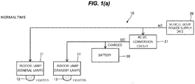
- Figure 1 is a block diagram schematically showing one example of a lighting device 10 that is loaded in a railroad vehicle 1.
- the railroad vehicle 1 is normally formed by a plurality of vehicles, consisting of a first vehicle having a crew room, and intermediate vehicles, however, the lighting device 10 that is loaded in one vehicle is taken as a representative for explanation.
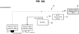
- Figure 2 is a cross sectional view schematically showing a top portion of the cabin of the railroad vehicle 1.
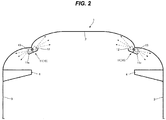
- Figure 3 is a schematic diagram schematically showing an arrangement of the seats, the doors, and the lighting device 10 on a ceiling 2 in the cabin of the railroad vehicle 1.
- the lighting device 10 is disposed on the ceiling 2 in the cabin of the railroad vehicle 1, including a plurality of indoor lamps 11 as lighting fixtures.
- the indoor lamp 11 has a shape that allows extension thereof in the longitudinal direction thereof, as later described, and the plurality of indoor lamps 11 are arranged on the ceiling 2 from one end thereof to the other in parallel with the longitudinal direction of the vehicle, being linearly connected with one another. Thereby, the indoor lamps 11 are arranged so as to wholly irradiate the inside of the cabin over the longitudinal direction of the vehicle.
- the arrangement of the seats, etc. in the cabin of the railroad vehicle 1 varies, depending upon the type of vehicle, such as the commuter train or the limited express train, as described in connection with the background art.
- the indoor lamps 11 are disposed in such a way that they are arranged in two rows on the right and left sides about the center line of the vehicle that extends along the longitudinal direction thereof, each in a location closer to a side wall 3 on the ceiling 2.
- the indoor lamps 11 are disposed such that the required illuminance can be secured in the cabin also in a crosswise direction of the vehicle.
- the lighting device 10 in addition to a plurality of indoor lamps 11, which are arranged so as to wholly irradiate the inside of the cabin over the longitudinal direction of the vehicle, the lighting device 10 includes such components as a vehicle body power supply (power supply) 20, which supplies electric power to the respective indoor lamps 11, and a battery (storage battery) 30, which is charged with a voltage applied by the vehicle body power supply 20.
- a vehicle body power supply power supply
- the indoor lamps 11 and the battery 30 are disposed in the same manner in each vehicle, however, it is enough that the vehicle body power supply 20 is provided only for one vehicle, such as the first vehicle.
- one unit that constitutes each individual lighting fixture includes a general lamp light source 12 as a first light source, and a standby lamp light source 13 as a second light source, which is lighted at an illuminance lower than that at which the general lamp light source 12 is lighted.
- the general lamp light source 12 and the standby lamp light source 13 in the indoor lamp 11 are illustrated separately for convenience, however, those light sources 12 and 13 are collectively incorporated in each indoor lamp 11 provided as one unit.
- the indoor lamp 11 includes a casing 11a, having a shape allowing extension in the longitudinal direction thereof, and as described above, a plurality of the respective indoor lamps 11 are disposed in parallel with the longitudinal direction of the vehicle on the ceiling 2 of the cabin in a state of one being extended to another.
- the general lamp light source 12 is disposed on one side of the casing 11a that extends in the longitudinal direction thereof, being located closer to the inside of the cabin than the center line of the casing 11a, while the standby lamp light source 13 of the indoor lamps 11 being disposed on the other side of the casing 11a that extends in the longitudinal direction thereof, being located closer to the outside of the cabin than the center line of the casing 11a.
- the irradiation direction of the general lamp light source 12 is established to be a direction toward the center of the ceiling 2, which is a predetermined irradiation direction therefor.
- the irradiation direction of the standby lamp light source 13 is specified to be a direction toward the upper portion of the side wall 3, which is a direction different from that for the general lamp light source 12.
- the general lamp light source 12 illuminates the whole of the inside of the cabin with indirect light from the ceiling 2 as a main illuminator.
- the standby lamp light source 13 illuminates the inside of a luggage rack 4, which is provided in the upper portion of the side wall 3, with direct light as an auxiliary illuminator.
- the indoor lamp 11 shown in Figure 2 gives only one example of lighting fixture, however, any lighting fixture with any configuration is disposed in order to wholly irradiate the inside of the cabin over the longitudinal direction of the vehicle.
- "in order to wholly irradiate the inside of the cabin over the longitudinal direction of the vehicle” it is not always necessary for a plurality of the indoor lamps 11 to be disposed in a state in which one is extended to another, and even if a plurality of the indoor lamps 11 were disposed at a predetermined interval, a state in which the light from the plurality of the indoor lamps 11 irradiates almost uniformly in a contiguous manner in the inside of the cabin over the longitudinal direction of the vehicle can be achieved.
- the particular number of indoor lamps 11 is a design matter to be determined in accordance with the size of the individual unit and the size of the vehicle.
- one general lamp light source 12 and one standby lamp light source 13 are shown for convenience of explanation, however, as described above, actually, a plurality of indoor lamps 11, the number thereof having been determined as appropriate, are arranged in each vehicle in the same manner.
- a control device (not shown) is connected such that a variety of signals can be transmitted thereto or received therefrom.
- the control device executes lighting control, such as dimming, of the light sources 12 and 13.
- the illuminance of the standby lamp light source 13 may be lower than that of the general lamp light source 12 to such a degree that, in an emergency, the light emitted from the standby lamp light source 13 toward the floor allows the passengers to identify their feet.
- the standby lamp 13 is not such a one like a conventional standby lamp, which is installed only in the vicinity of the door, and in an emergency, locally illuminates only the area near the door brightly, but a one that, even if darker, can wholly irradiate the inside of the cabin over the longitudinal direction of the vehicle. Assuming that the illuminance of the general lamp light source 12 at the normal time is 100%, for example, the illuminance of the standby lamp light source 13 can be set at as low as 10 to 20%.
- the LED is suitable for use.
- the LED offers such advantages as not only it being easy to be controlled for dimming and color matching, but also it being compact, consuming less power, and having a long service life.
- the light sources 12 and 13 are configured by mounting a plurality of them on a narrow substrate at equal intervals, for example.
- the LED emits light within a predetermined angular range of irradiation about the optical axis thereof, and the orientation of the optical axis determines the irradiation direction.
- the light sources 12 and 13 are not always limited to the LED, but as them, such a part as a small-sized electric bulb may be adopted.
- the vehicle body power supply 20 supplies electric power to the indoor lamps 11, being normally loaded in one vehicle, such as the first one, with a wiring for supplying electric power to each vehicle being extended therefrom.
- the vehicle body power supply 20 is configured such that it is supplied with electric power from outside, for example, from an overhead contact line through a pantograph, or the like, and supplies electric power not only to the indoor lamps 11, but also to the other loads.
- the loads other than the indoor lamps 11 refer to such components as door opening and closing apparatuses and information displays (monitors).
- the vehicle body power supply 20 supplies an alternating current to the loads including the indoor lamps 11, and with the wiring for the lighting device 10, the alternating current is supplied to the general lamp light source 12 as it is, while, to the standby lamp light source 13, a direct current, which is provided as a result of converting the alternating current by the later-described AC-DC conversion circuit 21, being supplied through the battery 30.
- a direct current which is provided as a result of converting the alternating current by the later-described AC-DC conversion circuit 21, being supplied through the battery 30.
- the configuration shown in Figure 1 will be altered depending upon the condition for supply of the direct current.
- the battery 30 is, for example, a storage battery that is provided by connecting a plurality of battery cells in series, and thereto, an AC-DC conversion circuit 21 is attached. To or from the battery 30, a direct current at a low voltage that is obtained as a result of conversion by the AC-DC conversion circuit 21 is inputted or outputted.
- the AC-DC conversion circuit 21 is a circuit that converts the alternating current supplied from the vehicle body power supply 20 into a direct current at a low voltage, and outputs it for charging the battery 30.
- the battery 30 is disposed under the floor of each vehicle, for example.
- the circuit and wiring for the indoor lamp 11 is configured such that, to the general lamp light source 12 of the indoor lamp 11, electric power is supplied from the vehicle body power supply 20 not through the battery 30, while, to the standby lamp light source 13, electric power is supplied from the vehicle body power supply 20 through the battery 30.
- components such as a switch for switching over the power feeding to that from the battery 30, and a circuit for dimming control of the light sources 12 and 13, are not provided in particular.
- the indoor lamp 11 which illuminates the inside of the cabin of the railroad vehicle 1, is provided in order to wholly irradiate the inside of the cabin over the longitudinal direction of the vehicle.
- the indoor lamp 11 can be extended to a desired length by linearly connecting a plurality of the casings 11a, extending in the longitudinal direction thereof, one with another, whereby the indoor lamps 11 can be disposed on the ceiling 2 in parallel with the longitudinal direction of the vehicle from one end thereof to the other. Thereby, the indoor lamps 11 can irradiate the entire inside of the cabin over the longitudinal direction of the vehicle.
- the indoor lamps 11 are arranged in two rows such that they are symmetrically disposed about the center line of the ceiling 2, whereby they can illuminate the inside of the cabin in a wide range with a good balance from both right and left sides.
- the indoor lamp 11 includes the general lamp light source 12 and the standby lamp light source 13, which is lighted at an illuminance lower than that at which the general lamp light source 12 is lighted.
- the irradiation by the general lamp light source 12 and that by the standby lamp light source 13 are both executed in order to wholly illuminate the inside of the cabin over the longitudinal direction of the vehicle as with that by the conventional general lamp, and are not executed to locally illuminate only the area in the vicinity of the door inside of the cabin as with that by the conventional standby lamp.
- the illuminance of the standby lamp light source 13 can be as low as, for example, 10 to 20% of that of the general lamp light source 12, in other words, it may be low to such a degree that the light emitted from the standby lamp light source 13 toward the floor allows the passengers to identify their feet in an emergency.
- the irradiation direction for the general lamp light source 12 is specified to be a direction toward the center of the ceiling 2, and at the normal time, the general lamp light source 12 illuminates the whole of the inside of the cabin with indirect light from the ceiling 2 as a main illuminator.
- the irradiation direction for the standby lamp light source 13 differs from that for the general lamp light source 12, being specified to be a direction toward the upper portion of the side wall 3, and the standby lamp light source 13 illuminates the inside of the luggage rack 4 installed in the upper portion of the side wall 3 with direct light as an auxiliary illuminator. In this way, by providing the light from the light source 12 and that from the light source 13 with different irradiation directions, illuminators having different applications can be realized even in a single indoor lamp 11.
- the general lamp light source 12 is supplied with electric power from the vehicle body power supply 20 not through the battery 30.
- the standby lamp light source 13 is supplied with electric power from the vehicle body power supply 20 through the battery 30.
- the standby lamp light source 13 is supplied with electric power from the battery 30, thereby the standby lamp light source 13 being continued to be lighted at a low illuminance without being extinguished.
- the standby lamp is disposed only at the vehicle end. Therefore, as can been seen from Figure 5(a) , which indicates the illuminance distribution (that in the vehicle section along the direction of the rail) for the conventional lighting device, the illuminance in the inside of the cabin along the longitudinal direction in an emergency with the conventional lighting device has been bright only in the area in the vicinity of the cabin entrance at the vehicle end, while, in the area especially at the center of the vehicle, the illuminance has been dark, thereby the difference in illuminance between the area at the vehicle end and the areas other than that at the vehicle end having been great.
- the illuminance difference between the area in the vicinity of the vehicle end, where the standby lamp is installed, and the area at the center of the vehicle, which is away from the standby lamp, has been great, thereby the passengers in the dark area being difficult to identify their feet when they make evacuation, and thus there has been a room for improvement of the safety at the time of evacuation.
- the standby lamp light source 13 which is included in every indoor lamp 11 in any vehicle, will function as a standby lamp in an emergency to wholly irradiate the inside of the cabin over the longitudinal direction of the vehicle even though at a low illuminance.
- the uniformity in illuminance in the inside of the cabin in an emergency is improved as compared to that with the conventional lighting device, whereby a minimum illuminance that is required for the passengers to evacuate from the inside of the cabin can be secured over the longitudinal direction of the vehicle, and the passengers, even if being in any location in the inside of the cabin, can evacuate safely.
- the standby lamp light source 13 is supplied with power from the battery 30 in an emergency, the duration of illumination is limited by the capacity of the battery, and in the case where the supply of power from the vehicle body power supply 20 is shut off for a long period of time, there is the possibility that the lighting of the standby lamp light source 13 may not be able to be maintained.
- the standby lamp light source 13 is specified to be of a power saving type, which provides lighting at a low illuminance also at the normal time, whereby the lighting thereof can be maintained over a period of time as long as possible within the predetermined range of capacity of the battery 30. For example, both in the case where two general lamp light sources 12 are lighted at 100% and in the case where twenty standby lamp light sources 13 are lighted at 10%, it can be considered that the power consumption is the same in both cases.
- the relation between the capacity of the battery 30 and the illuminance of the standby lamp light source 13 can be established such that, in the event that the supply of power from the vehicle body power supply 20 is suddenly shut off, the lighting of the standby lamp light source 13 can be maintained for a period of 30 minutes with the power supplied from the battery 30, which is always charged to 100% at the normal time. Even in an emergency, the condition of power feeding from the battery 30 to the standby lamp light source 13 will not be subjected to any change or switched over. If it is possible to be implemented only with the configuration of the circuit itself with no need for performing a special control with the control device, the illuminance may be automatically changed over to, for example, a further low one in an emergency.
- the wiring for supplying power from the vehicle body power supply 20 to the general lamp light source 12 and the wiring for supplying power from the vehicle body power supply 20 to the standby lamp light source 13 can be unified into one for common use. Since the general lamp light source 12 and the standby lamp light source 13 are included in the same indoor lamp 11, the length of the wiring can be reduced by the shortened distance between them, whereby the cost can be reduced with a substantial increase in weight being suppressed.
- the vehicle body power supply 20 supplies electric power obtained from the outside of the vehicle to the loads including the indoor lamp 11.
- the vehicle body power supply 20 it is possible to continuously and stably supply a predetermined quantity of electric power with no need for increasing the capacity in particular, always charging the battery 30, and the vehicle body power supply 20 can be widely used also as a vehicle body power supply for supplying power to the loads other than the indoor lamp 11.
- the wiring and circuit for the standby lamp light source 13 includes the AC-DC conversion circuit 21, which converts the alternating current from the vehicle body power supply 20 to output a direct current, the battery 30 being charged with a DC voltage from the AC-DC conversion circuit 21. Then, the standby lamp light source 13 is lighted with the DC voltage applied by the battery 30. In this way, even if the electric current from the vehicle body power supply 20 is an alternating current, a storage battery, which is charged with a DC voltage, can be readily accommodated.
- the indoor lamp 11 of the lighting device 10 is that which is installed on the ceiling 2 in the inside of the cabin of the railroad vehicle 1, however, it may be that which is installed as an illuminator in the inside of the cabin of any other vehicle, such as a monorail car or a bus.
- the specific geometry of the indoor lamp 11 is not limited to the example which is shown.
- the present invention is widely applicable to a lighting device that is loaded in vehicles, such as the railroad vehicle, and is used to illuminate the inside of the cabin of the vehicle.
- Reference numeral 1 denotes a railroad vehicle; 2 a ceiling; 3 a side wall; 4 a luggage rack; 10 a lighting device; 11 an indoor lamp (lighting fixture); 11a a casing; 12 a general lamp light source (first light source); 13 a standby lamp light source (second light source); 20 a vehicle body power supply (power supply); 21 an AC-DC conversion circuit (conversion circuit); and 30 a battery (storage battery).
Landscapes
- Engineering & Computer Science (AREA)
- Mechanical Engineering (AREA)
- Arrangements Of Lighting Devices For Vehicle Interiors, Mounting And Supporting Thereof, Circuits Therefore (AREA)
- Circuit Arrangement For Electric Light Sources In General (AREA)
Applications Claiming Priority (2)
| Application Number | Priority Date | Filing Date | Title |
|---|---|---|---|
| JP2018043637A JP7239270B2 (ja) | 2018-03-09 | 2018-03-09 | 照明装置 |
| PCT/JP2019/009410 WO2019172435A1 (fr) | 2018-03-09 | 2019-03-08 | Dispositif d'éclairage |
Publications (3)
| Publication Number | Publication Date |
|---|---|
| EP3764744A1 true EP3764744A1 (fr) | 2021-01-13 |
| EP3764744A4 EP3764744A4 (fr) | 2021-04-14 |
| EP3764744B1 EP3764744B1 (fr) | 2024-07-03 |
Family
ID=67846692
Family Applications (1)
| Application Number | Title | Priority Date | Filing Date |
|---|---|---|---|
| EP19763303.5A Active EP3764744B1 (fr) | 2018-03-09 | 2019-03-08 | Dispositif d'éclairage |
Country Status (6)
| Country | Link |
|---|---|
| US (1) | US11665805B2 (fr) |
| EP (1) | EP3764744B1 (fr) |
| JP (1) | JP7239270B2 (fr) |
| CN (1) | CN111989987A (fr) |
| TW (1) | TWI800611B (fr) |
| WO (1) | WO2019172435A1 (fr) |
Cited By (1)
| Publication number | Priority date | Publication date | Assignee | Title |
|---|---|---|---|---|
| EP4064795A1 (fr) * | 2021-03-25 | 2022-09-28 | Schmitz Cargobull AG | Commande de l'éclairage intérieur d'un véhicule utilitaire |
Family Cites Families (13)
| Publication number | Priority date | Publication date | Assignee | Title |
|---|---|---|---|---|
| JPS4875487U (fr) * | 1971-12-22 | 1973-09-19 | ||
| US7956490B2 (en) * | 2009-09-16 | 2011-06-07 | Jack Sotnikow | Battery backup for vehicle emergency communicator |
| CN201657420U (zh) * | 2010-03-19 | 2010-11-24 | 南车青岛四方机车车辆股份有限公司 | 轨道车辆客室照明控制系统 |
| SK50532010A3 (sk) * | 2010-12-15 | 2012-07-03 | S Power Export-Import, S. R. O. | Involvement of the main and emergency lighting |
| KR101320670B1 (ko) * | 2012-02-06 | 2013-10-23 | 박성훈 | 엘이디 조명의 충전시스템 및 정전감지 장치 |
| CN102991363B (zh) * | 2012-12-07 | 2015-08-05 | 南车株洲电力机车有限公司 | 一种城轨车辆的蓄电池与受电弓牵引供电系统 |
| JP6118550B2 (ja) | 2012-12-17 | 2017-04-19 | 川重車両テクノ株式会社 | 照明装置、及び照明システム |
| US8941311B2 (en) * | 2013-04-09 | 2015-01-27 | Bombardier Transportation Gmbh | Control of the intensity of a LED lighting system |
| US9877374B2 (en) * | 2014-11-25 | 2018-01-23 | Cree, Inc. | Lighting apparatus and methods providing variable illumination characteristics based on object detection |
| TWM515984U (zh) * | 2014-12-31 | 2016-01-21 | wen-tian Cai | 具多組電池的電動車供電系統 |
| JP6570868B2 (ja) | 2015-04-27 | 2019-09-04 | コイト電工株式会社 | 鉄道車両用室内照明システム及び室内灯ユニット |
| JP6807156B2 (ja) | 2016-01-29 | 2021-01-06 | コイト電工株式会社 | 電源システム及び鉄道用車両 |
| CN107734739A (zh) * | 2017-08-31 | 2018-02-23 | 今创集团股份有限公司 | 地铁车辆自调光led照明灯具控制系统 |
-
2018
- 2018-03-09 JP JP2018043637A patent/JP7239270B2/ja active Active
-
2019
- 2019-03-07 TW TW108107532A patent/TWI800611B/zh active
- 2019-03-08 CN CN201980017774.6A patent/CN111989987A/zh active Pending
- 2019-03-08 WO PCT/JP2019/009410 patent/WO2019172435A1/fr not_active Ceased
- 2019-03-08 US US16/979,286 patent/US11665805B2/en active Active
- 2019-03-08 EP EP19763303.5A patent/EP3764744B1/fr active Active
Cited By (1)
| Publication number | Priority date | Publication date | Assignee | Title |
|---|---|---|---|---|
| EP4064795A1 (fr) * | 2021-03-25 | 2022-09-28 | Schmitz Cargobull AG | Commande de l'éclairage intérieur d'un véhicule utilitaire |
Also Published As
| Publication number | Publication date |
|---|---|
| WO2019172435A1 (fr) | 2019-09-12 |
| CN111989987A (zh) | 2020-11-24 |
| US20200398744A1 (en) | 2020-12-24 |
| EP3764744B1 (fr) | 2024-07-03 |
| EP3764744A4 (fr) | 2021-04-14 |
| TW201945222A (zh) | 2019-12-01 |
| JP7239270B2 (ja) | 2023-03-14 |
| US11665805B2 (en) | 2023-05-30 |
| JP2019160499A (ja) | 2019-09-19 |
| TWI800611B (zh) | 2023-05-01 |
Similar Documents
| Publication | Publication Date | Title |
|---|---|---|
| EP2790471B1 (fr) | Commande de l'intensité d'un système d'éclairage à del | |
| US20110163697A1 (en) | Cabin illuminating device of aircraft | |
| EP2444294A1 (fr) | Wagon de train équipé d'un système d'éclairage par LED et procédé de commande du système d'éclairage par LED dans un wagon de train | |
| JP6118550B2 (ja) | 照明装置、及び照明システム | |
| US11665805B2 (en) | Lighting device | |
| US20050141226A1 (en) | Emergency lighting arrangement with decentralized emergency power supply for an aircraft | |
| EP2803551B1 (fr) | Système d'éclairage à DEL pour véhicule ferroviaire | |
| KR101816348B1 (ko) | 철도차량 객실의 led 조명등 설치시 배선을 최소화하는 전기회로를 구비한 철도차량의 조명제어 시스템 | |
| JP2015024740A (ja) | 移動体の車内表示器及び車内情報表示装置 | |
| CA2803193C (fr) | Eclairage de secours de vehicule sur rails | |
| CN206781761U (zh) | 一种城市轨道交通车辆客室照明系统及城市轨道交通车辆 | |
| US10668811B2 (en) | Power supply system and railroad car | |
| US20070069657A1 (en) | Elevator lights | |
| KR20110012755A (ko) | Led 조명을 이용한 패널 | |
| FI114195B (fi) | Järjestely valaisimen yhteydessä | |
| JP2004277111A (ja) | エレベータ電源システム | |
| ES2550944T3 (es) | Módulo luminoso de un vehículo ferroviario | |
| CN207246959U (zh) | 一种高速列车车厢led灯光照明灯具 | |
| BG2830U1 (bg) | Контролирана светодиодна осветителна система за железопътни превозни средства | |
| HK1170715B (en) | Emergency lighting for an elevator cab | |
| HK1170715A1 (en) | Emergency lighting for an elevator cab |
Legal Events
| Date | Code | Title | Description |
|---|---|---|---|
| STAA | Information on the status of an ep patent application or granted ep patent |
Free format text: STATUS: THE INTERNATIONAL PUBLICATION HAS BEEN MADE |
|
| PUAI | Public reference made under article 153(3) epc to a published international application that has entered the european phase |
Free format text: ORIGINAL CODE: 0009012 |
|
| STAA | Information on the status of an ep patent application or granted ep patent |
Free format text: STATUS: REQUEST FOR EXAMINATION WAS MADE |
|
| 17P | Request for examination filed |
Effective date: 20201007 |
|
| AK | Designated contracting states |
Kind code of ref document: A1 Designated state(s): AL AT BE BG CH CY CZ DE DK EE ES FI FR GB GR HR HU IE IS IT LI LT LU LV MC MK MT NL NO PL PT RO RS SE SI SK SM TR |
|
| AX | Request for extension of the european patent |
Extension state: BA ME |
|
| REG | Reference to a national code |
Ref legal event code: R079 Ipc: B60Q0003430000 Ref country code: DE Ref legal event code: R079 Ref document number: 602019054617 Country of ref document: DE Free format text: PREVIOUS MAIN CLASS: H05B0037020000 Ipc: B60Q0003430000 |
|
| A4 | Supplementary search report drawn up and despatched |
Effective date: 20210312 |
|
| RIC1 | Information provided on ipc code assigned before grant |
Ipc: B60Q 3/43 20170101AFI20210305BHEP Ipc: B60Q 3/47 20170101ALI20210305BHEP Ipc: B61D 29/00 20060101ALI20210305BHEP Ipc: H05B 47/17 20200101ALI20210305BHEP |
|
| DAV | Request for validation of the european patent (deleted) | ||
| DAX | Request for extension of the european patent (deleted) | ||
| STAA | Information on the status of an ep patent application or granted ep patent |
Free format text: STATUS: EXAMINATION IS IN PROGRESS |
|
| 17Q | First examination report despatched |
Effective date: 20220721 |
|
| GRAP | Despatch of communication of intention to grant a patent |
Free format text: ORIGINAL CODE: EPIDOSNIGR1 |
|
| STAA | Information on the status of an ep patent application or granted ep patent |
Free format text: STATUS: GRANT OF PATENT IS INTENDED |
|
| INTG | Intention to grant announced |
Effective date: 20230921 |
|
| GRAJ | Information related to disapproval of communication of intention to grant by the applicant or resumption of examination proceedings by the epo deleted |
Free format text: ORIGINAL CODE: EPIDOSDIGR1 |
|
| STAA | Information on the status of an ep patent application or granted ep patent |
Free format text: STATUS: EXAMINATION IS IN PROGRESS |
|
| INTC | Intention to grant announced (deleted) | ||
| GRAP | Despatch of communication of intention to grant a patent |
Free format text: ORIGINAL CODE: EPIDOSNIGR1 |
|
| STAA | Information on the status of an ep patent application or granted ep patent |
Free format text: STATUS: GRANT OF PATENT IS INTENDED |
|
| INTG | Intention to grant announced |
Effective date: 20240313 |
|
| GRAS | Grant fee paid |
Free format text: ORIGINAL CODE: EPIDOSNIGR3 |
|
| GRAA | (expected) grant |
Free format text: ORIGINAL CODE: 0009210 |
|
| STAA | Information on the status of an ep patent application or granted ep patent |
Free format text: STATUS: THE PATENT HAS BEEN GRANTED |
|
| AK | Designated contracting states |
Kind code of ref document: B1 Designated state(s): AL AT BE BG CH CY CZ DE DK EE ES FI FR GB GR HR HU IE IS IT LI LT LU LV MC MK MT NL NO PL PT RO RS SE SI SK SM TR |
|
| REG | Reference to a national code |
Ref country code: CH Ref legal event code: EP |
|
| REG | Reference to a national code |
Ref country code: DE Ref legal event code: R096 Ref document number: 602019054617 Country of ref document: DE |
|
| REG | Reference to a national code |
Ref country code: LT Ref legal event code: MG9D |
|
| REG | Reference to a national code |
Ref country code: NL Ref legal event code: MP Effective date: 20240703 |
|
| PG25 | Lapsed in a contracting state [announced via postgrant information from national office to epo] |
Ref country code: PT Free format text: LAPSE BECAUSE OF FAILURE TO SUBMIT A TRANSLATION OF THE DESCRIPTION OR TO PAY THE FEE WITHIN THE PRESCRIBED TIME-LIMIT Effective date: 20241104 |
|
| REG | Reference to a national code |
Ref country code: AT Ref legal event code: MK05 Ref document number: 1699509 Country of ref document: AT Kind code of ref document: T Effective date: 20240703 |
|
| PG25 | Lapsed in a contracting state [announced via postgrant information from national office to epo] |
Ref country code: NL Free format text: LAPSE BECAUSE OF FAILURE TO SUBMIT A TRANSLATION OF THE DESCRIPTION OR TO PAY THE FEE WITHIN THE PRESCRIBED TIME-LIMIT Effective date: 20240703 |
|
| PG25 | Lapsed in a contracting state [announced via postgrant information from national office to epo] |
Ref country code: PT Free format text: LAPSE BECAUSE OF FAILURE TO SUBMIT A TRANSLATION OF THE DESCRIPTION OR TO PAY THE FEE WITHIN THE PRESCRIBED TIME-LIMIT Effective date: 20241104 Ref country code: NL Free format text: LAPSE BECAUSE OF FAILURE TO SUBMIT A TRANSLATION OF THE DESCRIPTION OR TO PAY THE FEE WITHIN THE PRESCRIBED TIME-LIMIT Effective date: 20240703 |
|
| PG25 | Lapsed in a contracting state [announced via postgrant information from national office to epo] |
Ref country code: NO Free format text: LAPSE BECAUSE OF FAILURE TO SUBMIT A TRANSLATION OF THE DESCRIPTION OR TO PAY THE FEE WITHIN THE PRESCRIBED TIME-LIMIT Effective date: 20241003 |
|
| PG25 | Lapsed in a contracting state [announced via postgrant information from national office to epo] |
Ref country code: FI Free format text: LAPSE BECAUSE OF FAILURE TO SUBMIT A TRANSLATION OF THE DESCRIPTION OR TO PAY THE FEE WITHIN THE PRESCRIBED TIME-LIMIT Effective date: 20240703 Ref country code: GR Free format text: LAPSE BECAUSE OF FAILURE TO SUBMIT A TRANSLATION OF THE DESCRIPTION OR TO PAY THE FEE WITHIN THE PRESCRIBED TIME-LIMIT Effective date: 20241004 Ref country code: PL Free format text: LAPSE BECAUSE OF FAILURE TO SUBMIT A TRANSLATION OF THE DESCRIPTION OR TO PAY THE FEE WITHIN THE PRESCRIBED TIME-LIMIT Effective date: 20240703 |
|
| PG25 | Lapsed in a contracting state [announced via postgrant information from national office to epo] |
Ref country code: BG Free format text: LAPSE BECAUSE OF FAILURE TO SUBMIT A TRANSLATION OF THE DESCRIPTION OR TO PAY THE FEE WITHIN THE PRESCRIBED TIME-LIMIT Effective date: 20240703 |
|
| PG25 | Lapsed in a contracting state [announced via postgrant information from national office to epo] |
Ref country code: LV Free format text: LAPSE BECAUSE OF FAILURE TO SUBMIT A TRANSLATION OF THE DESCRIPTION OR TO PAY THE FEE WITHIN THE PRESCRIBED TIME-LIMIT Effective date: 20240703 |
|
| PG25 | Lapsed in a contracting state [announced via postgrant information from national office to epo] |
Ref country code: IS Free format text: LAPSE BECAUSE OF FAILURE TO SUBMIT A TRANSLATION OF THE DESCRIPTION OR TO PAY THE FEE WITHIN THE PRESCRIBED TIME-LIMIT Effective date: 20241103 Ref country code: AT Free format text: LAPSE BECAUSE OF FAILURE TO SUBMIT A TRANSLATION OF THE DESCRIPTION OR TO PAY THE FEE WITHIN THE PRESCRIBED TIME-LIMIT Effective date: 20240703 |
|
| PG25 | Lapsed in a contracting state [announced via postgrant information from national office to epo] |
Ref country code: HR Free format text: LAPSE BECAUSE OF FAILURE TO SUBMIT A TRANSLATION OF THE DESCRIPTION OR TO PAY THE FEE WITHIN THE PRESCRIBED TIME-LIMIT Effective date: 20240703 Ref country code: CZ Free format text: LAPSE BECAUSE OF FAILURE TO SUBMIT A TRANSLATION OF THE DESCRIPTION OR TO PAY THE FEE WITHIN THE PRESCRIBED TIME-LIMIT Effective date: 20240703 |
|
| PG25 | Lapsed in a contracting state [announced via postgrant information from national office to epo] |
Ref country code: ES Free format text: LAPSE BECAUSE OF FAILURE TO SUBMIT A TRANSLATION OF THE DESCRIPTION OR TO PAY THE FEE WITHIN THE PRESCRIBED TIME-LIMIT Effective date: 20240703 Ref country code: RS Free format text: LAPSE BECAUSE OF FAILURE TO SUBMIT A TRANSLATION OF THE DESCRIPTION OR TO PAY THE FEE WITHIN THE PRESCRIBED TIME-LIMIT Effective date: 20241003 |
|
| PG25 | Lapsed in a contracting state [announced via postgrant information from national office to epo] |
Ref country code: RS Free format text: LAPSE BECAUSE OF FAILURE TO SUBMIT A TRANSLATION OF THE DESCRIPTION OR TO PAY THE FEE WITHIN THE PRESCRIBED TIME-LIMIT Effective date: 20241003 Ref country code: PL Free format text: LAPSE BECAUSE OF FAILURE TO SUBMIT A TRANSLATION OF THE DESCRIPTION OR TO PAY THE FEE WITHIN THE PRESCRIBED TIME-LIMIT Effective date: 20240703 Ref country code: NO Free format text: LAPSE BECAUSE OF FAILURE TO SUBMIT A TRANSLATION OF THE DESCRIPTION OR TO PAY THE FEE WITHIN THE PRESCRIBED TIME-LIMIT Effective date: 20241003 Ref country code: LV Free format text: LAPSE BECAUSE OF FAILURE TO SUBMIT A TRANSLATION OF THE DESCRIPTION OR TO PAY THE FEE WITHIN THE PRESCRIBED TIME-LIMIT Effective date: 20240703 Ref country code: IS Free format text: LAPSE BECAUSE OF FAILURE TO SUBMIT A TRANSLATION OF THE DESCRIPTION OR TO PAY THE FEE WITHIN THE PRESCRIBED TIME-LIMIT Effective date: 20241103 Ref country code: HR Free format text: LAPSE BECAUSE OF FAILURE TO SUBMIT A TRANSLATION OF THE DESCRIPTION OR TO PAY THE FEE WITHIN THE PRESCRIBED TIME-LIMIT Effective date: 20240703 Ref country code: GR Free format text: LAPSE BECAUSE OF FAILURE TO SUBMIT A TRANSLATION OF THE DESCRIPTION OR TO PAY THE FEE WITHIN THE PRESCRIBED TIME-LIMIT Effective date: 20241004 Ref country code: FI Free format text: LAPSE BECAUSE OF FAILURE TO SUBMIT A TRANSLATION OF THE DESCRIPTION OR TO PAY THE FEE WITHIN THE PRESCRIBED TIME-LIMIT Effective date: 20240703 Ref country code: ES Free format text: LAPSE BECAUSE OF FAILURE TO SUBMIT A TRANSLATION OF THE DESCRIPTION OR TO PAY THE FEE WITHIN THE PRESCRIBED TIME-LIMIT Effective date: 20240703 Ref country code: CZ Free format text: LAPSE BECAUSE OF FAILURE TO SUBMIT A TRANSLATION OF THE DESCRIPTION OR TO PAY THE FEE WITHIN THE PRESCRIBED TIME-LIMIT Effective date: 20240703 Ref country code: BG Free format text: LAPSE BECAUSE OF FAILURE TO SUBMIT A TRANSLATION OF THE DESCRIPTION OR TO PAY THE FEE WITHIN THE PRESCRIBED TIME-LIMIT Effective date: 20240703 Ref country code: AT Free format text: LAPSE BECAUSE OF FAILURE TO SUBMIT A TRANSLATION OF THE DESCRIPTION OR TO PAY THE FEE WITHIN THE PRESCRIBED TIME-LIMIT Effective date: 20240703 |
|
| REG | Reference to a national code |
Ref country code: DE Ref legal event code: R097 Ref document number: 602019054617 Country of ref document: DE |
|
| PG25 | Lapsed in a contracting state [announced via postgrant information from national office to epo] |
Ref country code: DK Free format text: LAPSE BECAUSE OF FAILURE TO SUBMIT A TRANSLATION OF THE DESCRIPTION OR TO PAY THE FEE WITHIN THE PRESCRIBED TIME-LIMIT Effective date: 20240703 Ref country code: SM Free format text: LAPSE BECAUSE OF FAILURE TO SUBMIT A TRANSLATION OF THE DESCRIPTION OR TO PAY THE FEE WITHIN THE PRESCRIBED TIME-LIMIT Effective date: 20240703 Ref country code: RO Free format text: LAPSE BECAUSE OF FAILURE TO SUBMIT A TRANSLATION OF THE DESCRIPTION OR TO PAY THE FEE WITHIN THE PRESCRIBED TIME-LIMIT Effective date: 20240703 |
|
| PG25 | Lapsed in a contracting state [announced via postgrant information from national office to epo] |
Ref country code: EE Free format text: LAPSE BECAUSE OF FAILURE TO SUBMIT A TRANSLATION OF THE DESCRIPTION OR TO PAY THE FEE WITHIN THE PRESCRIBED TIME-LIMIT Effective date: 20240703 |
|
| PG25 | Lapsed in a contracting state [announced via postgrant information from national office to epo] |
Ref country code: IT Free format text: LAPSE BECAUSE OF FAILURE TO SUBMIT A TRANSLATION OF THE DESCRIPTION OR TO PAY THE FEE WITHIN THE PRESCRIBED TIME-LIMIT Effective date: 20240703 Ref country code: SK Free format text: LAPSE BECAUSE OF FAILURE TO SUBMIT A TRANSLATION OF THE DESCRIPTION OR TO PAY THE FEE WITHIN THE PRESCRIBED TIME-LIMIT Effective date: 20240703 |
|
| PLBE | No opposition filed within time limit |
Free format text: ORIGINAL CODE: 0009261 |
|
| STAA | Information on the status of an ep patent application or granted ep patent |
Free format text: STATUS: NO OPPOSITION FILED WITHIN TIME LIMIT |
|
| 26N | No opposition filed |
Effective date: 20250404 |
|
| PG25 | Lapsed in a contracting state [announced via postgrant information from national office to epo] |
Ref country code: SE Free format text: LAPSE BECAUSE OF FAILURE TO SUBMIT A TRANSLATION OF THE DESCRIPTION OR TO PAY THE FEE WITHIN THE PRESCRIBED TIME-LIMIT Effective date: 20240703 |
|
| PG25 | Lapsed in a contracting state [announced via postgrant information from national office to epo] |
Ref country code: MC Free format text: LAPSE BECAUSE OF FAILURE TO SUBMIT A TRANSLATION OF THE DESCRIPTION OR TO PAY THE FEE WITHIN THE PRESCRIBED TIME-LIMIT Effective date: 20240703 |
|
| REG | Reference to a national code |
Ref country code: CH Ref legal event code: H13 Free format text: ST27 STATUS EVENT CODE: U-0-0-H10-H13 (AS PROVIDED BY THE NATIONAL OFFICE) Effective date: 20251024 |
|
| PG25 | Lapsed in a contracting state [announced via postgrant information from national office to epo] |
Ref country code: LU Free format text: LAPSE BECAUSE OF NON-PAYMENT OF DUE FEES Effective date: 20250308 |
|
| REG | Reference to a national code |
Ref country code: BE Ref legal event code: MM Effective date: 20250331 |
|
| PG25 | Lapsed in a contracting state [announced via postgrant information from national office to epo] |
Ref country code: BE Free format text: LAPSE BECAUSE OF NON-PAYMENT OF DUE FEES Effective date: 20250331 |
|
| PG25 | Lapsed in a contracting state [announced via postgrant information from national office to epo] |
Ref country code: CH Free format text: LAPSE BECAUSE OF NON-PAYMENT OF DUE FEES Effective date: 20250331 |
|
| PG25 | Lapsed in a contracting state [announced via postgrant information from national office to epo] |
Ref country code: IE Free format text: LAPSE BECAUSE OF NON-PAYMENT OF DUE FEES Effective date: 20250308 |
|
| PGFP | Annual fee paid to national office [announced via postgrant information from national office to epo] |
Ref country code: GB Payment date: 20260324 Year of fee payment: 8 |
|
| PGFP | Annual fee paid to national office [announced via postgrant information from national office to epo] |
Ref country code: DE Payment date: 20260319 Year of fee payment: 8 |
|
| PGFP | Annual fee paid to national office [announced via postgrant information from national office to epo] |
Ref country code: FR Payment date: 20260323 Year of fee payment: 8 |