EP3764910B1 - Balayage entrelacé généralisé au moyen d'une sonde ultrasonore - Google Patents
Balayage entrelacé généralisé au moyen d'une sonde ultrasonore Download PDFInfo
- Publication number
- EP3764910B1 EP3764910B1 EP19716600.2A EP19716600A EP3764910B1 EP 3764910 B1 EP3764910 B1 EP 3764910B1 EP 19716600 A EP19716600 A EP 19716600A EP 3764910 B1 EP3764910 B1 EP 3764910B1
- Authority
- EP
- European Patent Office
- Prior art keywords
- scan
- motor
- plane
- planes
- interlacing
- Prior art date
- Legal status (The legal status is an assumption and is not a legal conclusion. Google has not performed a legal analysis and makes no representation as to the accuracy of the status listed.)
- Active
Links
Images








Classifications
-
- A—HUMAN NECESSITIES
- A61—MEDICAL OR VETERINARY SCIENCE; HYGIENE
- A61B—DIAGNOSIS; SURGERY; IDENTIFICATION
- A61B8/00—Diagnosis using ultrasonic, sonic or infrasonic waves
- A61B8/44—Constructional features of the ultrasonic, sonic or infrasonic diagnostic device
- A61B8/4444—Constructional features of the ultrasonic, sonic or infrasonic diagnostic device related to the probe
- A61B8/4461—Features of the scanning mechanism, e.g. for moving the transducer within the housing of the probe
-
- A—HUMAN NECESSITIES
- A61—MEDICAL OR VETERINARY SCIENCE; HYGIENE
- A61B—DIAGNOSIS; SURGERY; IDENTIFICATION
- A61B8/00—Diagnosis using ultrasonic, sonic or infrasonic waves
- A61B8/08—Clinical applications
- A61B8/0833—Clinical applications involving detecting or locating foreign bodies or organic structures
- A61B8/085—Clinical applications involving detecting or locating foreign bodies or organic structures for locating body or organic structures, e.g. tumours, calculi, blood vessels, nodules
-
- A—HUMAN NECESSITIES
- A61—MEDICAL OR VETERINARY SCIENCE; HYGIENE
- A61B—DIAGNOSIS; SURGERY; IDENTIFICATION
- A61B8/00—Diagnosis using ultrasonic, sonic or infrasonic waves
- A61B8/44—Constructional features of the ultrasonic, sonic or infrasonic diagnostic device
- A61B8/4444—Constructional features of the ultrasonic, sonic or infrasonic diagnostic device related to the probe
- A61B8/4461—Features of the scanning mechanism, e.g. for moving the transducer within the housing of the probe
- A61B8/4466—Features of the scanning mechanism, e.g. for moving the transducer within the housing of the probe involving deflection of the probe
-
- A—HUMAN NECESSITIES
- A61—MEDICAL OR VETERINARY SCIENCE; HYGIENE
- A61B—DIAGNOSIS; SURGERY; IDENTIFICATION
- A61B8/00—Diagnosis using ultrasonic, sonic or infrasonic waves
- A61B8/44—Constructional features of the ultrasonic, sonic or infrasonic diagnostic device
- A61B8/4444—Constructional features of the ultrasonic, sonic or infrasonic diagnostic device related to the probe
- A61B8/4472—Wireless probes
-
- A—HUMAN NECESSITIES
- A61—MEDICAL OR VETERINARY SCIENCE; HYGIENE
- A61B—DIAGNOSIS; SURGERY; IDENTIFICATION
- A61B8/00—Diagnosis using ultrasonic, sonic or infrasonic waves
- A61B8/48—Diagnostic techniques
- A61B8/483—Diagnostic techniques involving the acquisition of a 3D volume of data
-
- A—HUMAN NECESSITIES
- A61—MEDICAL OR VETERINARY SCIENCE; HYGIENE
- A61B—DIAGNOSIS; SURGERY; IDENTIFICATION
- A61B8/00—Diagnosis using ultrasonic, sonic or infrasonic waves
- A61B8/48—Diagnostic techniques
- A61B8/486—Diagnostic techniques involving arbitrary m-mode
-
- A—HUMAN NECESSITIES
- A61—MEDICAL OR VETERINARY SCIENCE; HYGIENE
- A61B—DIAGNOSIS; SURGERY; IDENTIFICATION
- A61B8/00—Diagnosis using ultrasonic, sonic or infrasonic waves
- A61B8/48—Diagnostic techniques
- A61B8/488—Diagnostic techniques involving Doppler signals
-
- A—HUMAN NECESSITIES
- A61—MEDICAL OR VETERINARY SCIENCE; HYGIENE
- A61B—DIAGNOSIS; SURGERY; IDENTIFICATION
- A61B8/00—Diagnosis using ultrasonic, sonic or infrasonic waves
- A61B8/52—Devices using data or image processing specially adapted for diagnosis using ultrasonic, sonic or infrasonic waves
- A61B8/5207—Devices using data or image processing specially adapted for diagnosis using ultrasonic, sonic or infrasonic waves involving processing of raw data to produce diagnostic data, e.g. for generating an image
-
- A—HUMAN NECESSITIES
- A61—MEDICAL OR VETERINARY SCIENCE; HYGIENE
- A61B—DIAGNOSIS; SURGERY; IDENTIFICATION
- A61B8/00—Diagnosis using ultrasonic, sonic or infrasonic waves
- A61B8/52—Devices using data or image processing specially adapted for diagnosis using ultrasonic, sonic or infrasonic waves
- A61B8/5269—Devices using data or image processing specially adapted for diagnosis using ultrasonic, sonic or infrasonic waves involving detection or reduction of artifacts
- A61B8/5276—Devices using data or image processing specially adapted for diagnosis using ultrasonic, sonic or infrasonic waves involving detection or reduction of artifacts due to motion
-
- A—HUMAN NECESSITIES
- A61—MEDICAL OR VETERINARY SCIENCE; HYGIENE
- A61B—DIAGNOSIS; SURGERY; IDENTIFICATION
- A61B8/00—Diagnosis using ultrasonic, sonic or infrasonic waves
- A61B8/54—Control of the diagnostic device
-
- A—HUMAN NECESSITIES
- A61—MEDICAL OR VETERINARY SCIENCE; HYGIENE
- A61B—DIAGNOSIS; SURGERY; IDENTIFICATION
- A61B8/00—Diagnosis using ultrasonic, sonic or infrasonic waves
- A61B8/08—Clinical applications
-
- A—HUMAN NECESSITIES
- A61—MEDICAL OR VETERINARY SCIENCE; HYGIENE
- A61B—DIAGNOSIS; SURGERY; IDENTIFICATION
- A61B8/00—Diagnosis using ultrasonic, sonic or infrasonic waves
- A61B8/44—Constructional features of the ultrasonic, sonic or infrasonic diagnostic device
- A61B8/4427—Device being portable or laptop-like
-
- A—HUMAN NECESSITIES
- A61—MEDICAL OR VETERINARY SCIENCE; HYGIENE
- A61B—DIAGNOSIS; SURGERY; IDENTIFICATION
- A61B8/00—Diagnosis using ultrasonic, sonic or infrasonic waves
- A61B8/44—Constructional features of the ultrasonic, sonic or infrasonic diagnostic device
- A61B8/4433—Constructional features of the ultrasonic, sonic or infrasonic diagnostic device involving a docking unit
Definitions
- An ultrasound probe may generate ultrasound signals using a transducer, such as, for example, a piezoelectric transducer or a capacitive transducer, which converts electrical signals into ultrasound energy and which converts ultrasound echoes back into electrical signals.
- Ultrasound probes are typically used to identify a target organ or other structures in the body and/or determine features associated with the target organ/structure, such as the size of the organ/structure or the volume of fluid in the organ.
- the ultrasound probe may need to perform scans in multiple planes to generate a volume scan. Performing scans in multiple planes may present various challenges.
- US2013/303913 discloses a method for three-dimensional ultrasonic imaging conducting a first group of line scans on a scanning object at a first group of scanning positions.
- US2016/192904 discloses an apparatus for measuring an amount of urine in a bladder using ultrasonic signals.
- An ultrasound probe may be positioned on a patient's body to perform a volume scan (e.g., a three-dimensional (3D) scan) of an area of interest, such as a body organ, joint, blood vessel, and/or another type of area of a patient's body.
- a volume scan may include a set of ultrasound images captured in different planes transecting the area of interest.
- a volume scan may include planar ultrasound images taken at particular angular intervals in a circle around a center of the area of interest.
- the ultrasound probe may include a single element ultrasound transducer.
- the ultrasound probe may include a first motor, referred to herein as a "phi” motor, configured to rotate around a horizontal plane to move the ultrasound transducer along a sector of a particular ultrasound imaging plane to scan the plane.
- the ultrasound probe may further include a second motor, referred to herein as a "theta” motor, configured to rotate around a vertical plane to move the ultrasound transducer to a different ultrasound imaging plane.
- a volume scan may be performed by moving the theta motor to a first plane, moving the phi motor to sweep out a sector of the first plane, moving the theta motor to a second plane, moving the phi motor to sweep out a sector of the second plane, moving the theta motor to a third plane, and so on until all the planes are scanned to complete one volume scan.
- a volume scan may be performed with theta homing.
- theta motor returns to the initial theta motor position after a volume scan is completed, in order to start the next volume scan.
- a volume scan may also be performed with phi homing.
- the phi motor In phi homing, the phi motor only performs scans in one direction. Thus, in phi homing, the phi motor returns back to an initial position after scanning a plane and the theta motor needs to wait for the phi motor to return before moving to the next plane.
- Theta homing and phi homing slow down scanning and reduce image quality. For example, theta homing may produce a large delay between consecutive volume scans and phi homing may increase the amount of time required to perform each individual volume scan. Furthermore, such slow volume scan rates may produce significant motion blur and reduce image quality.
- the interlaced scanning may include interlaced theta motor motion and bidirectional phi motor motion.
- the interlaced scanning may be performed without theta homing and without phi homing and generates a smooth continuous volume scan without homing delay, improved volume scan rate, and reduced motion blur.
- An interlaced scan may be defined by a number of scan planes.
- the scan planes may be distributed around a circle and separated by angles corresponding to 180° divided by the number of scan planes.
- the interlaced scan may further be defined by an interlacing factor k and the scan planes may be divided into k groups.
- the interlaced scan may follow a set of rules. The rules may include that the phi motor changes direction every plane, that the theta motor changes directions with every group of planes, and that the theta motor does not change directions within a group of planes. Furthermore, since no theta homing is performed, a first volume scan may be performed with the theta motor starting in a particular plane and followed by a second volume scan with the theta motor starting in a different plane.
- An ultrasound system may be configured to select a number of scan planes for an interlacing scan to scan a volume of an area of interest in a patient's body using an ultrasound transducer, select an interlacing factor for the interlacing scan, divide the scan planes into groups of scan planes based on the interlacing factor, and perform the interlacing scan by controlling a phi motor to scan a plane and a theta motor to move to a different plane, wherein the phi motor moves in a forward direction for at least some of the scan planes and in a backward direction for other ones of the scan planes. Furthermore, the theta motor may move in a forward direction for at least some of the groups of scan planes and in a backward direction for other ones of the groups of scan planes.
- dividing the scan planes into groups of scan planes based on the interlacing factor may include sequentially numbering the scan planes, dividing the scan planes into a number of groups of scan planes corresponding to the interlacing factor, and sequentially distributing the numbered scan planes into the groups of scan planes.
- performing the interlacing scan may include scanning a particular plane by moving the phi motor in a direction that is opposite to the direction the phi motor moved when scanning the previous plane; moving to a next plane by moving the theta motor by a number of planes corresponding to the interlacing factor, wherein the direction of the theta motor changes if the next plane is in a different group than the previously scanned plane.
- an ultrasound probe may include a one-dimensional (1D) linear or curved array of ultrasound transducers and a theta motor, instead of a single ultrasound transducer with a theta motor and a phi motor.
- movement of the phi motor to scan a plane may be replaced by electronically controlling the 1D array of ultrasound transducers to scan a plane.
- performing an interlacing scan may include controlling the 1D array of ultrasound transducers to scan a plane and controlling a motor configured to rotate the 1D array of ultrasound transducers around a vertical axis to move to a different plane, with the motor changing directions for every group of scan planes without changing directions within a group of scan planes.
- the interlacing scan may include scanning a particular plane by electronically controlling the 1D array of transducers, moving to a next plane by moving the theta motor a number of planes corresponding to the interlacing factor, wherein the direction of the theta motor changes if the next plane is in a different group than the previously scanned plane
- a particular implementation may include an interlacing scan with two scan planes and with the interlacing factor k being set to two. Such an implementation may result in continuous bi-plane scanning.
- Implementations described herein further relate to overlapping the motion of the phi motor and the theta motor.
- the arc of movement of a phi motor may include a region of acceleration, a region of constant speed, and a region of deceleration. Ultrasound image data collection may be performed within the region of constant speed while the theta motor remains still. However, since no data collection is performed during the acceleration or deceleration of the phi motor, movement of the theta motor during the time that the phi motor is accelerating or decelerating may improve the volume scan rate by reducing delays from phi motor acceleration/deceleration and/or theta motor movement.
- performing an interlacing scan may include controlling the theta motor to rotate while the phi motor is in the acceleration or deceleration region of the range of motion of the phi motor.
- the theta motor may move from a first plane to a second plane while the phi motor is in the acceleration or deceleration region of the range of motion.
- An ultrasound probe may include wiring, such as wiring to an ultrasound transducer.
- the wiring may limit the range of motion of the theta motor.
- the wiring may prevent the theta motor from continuously rotating in one direction, as such rotation may cause the wiring to wrap around a spindle attaching the ultrasound transducer to a base or may cause the wiring to break.
- An ultrasound probe may be configured to enable continuous theta motor movement.
- the wiring may be replaced with an electrically conducting slip ring.
- the wiring may be replaced with a wireless communication connection to the ultrasound transducer, such as a Bluetooth connection, a Bluetooth Low Energy connection, a Near Field Communication (NFC) connection, and/or another type of short-range wireless communication connection.
- performing an interlacing scan may include controlling the theta motor to move in a same direction for all the groups of scan planes.
- Fig. 1A is a diagram illustrating an exemplary ultrasound system 100 according to an implementation described herein.
- ultrasound system 100 may include an ultrasound probe 110, a base unit 120, and a cable 130.
- Ultrasound probe 110 may house one or more ultrasound transducers configured to generate ultrasound energy at a particular frequency and/or pulse repetition rate and to receive reflected ultrasound energy (e.g., ultrasound echoes) and convert the reflected ultrasound energy into electrical signals.
- ultrasound probe 110 may be configured to transmit ultrasound signals in a range that extends from approximately about two megahertz (MHz) to approximately 10 or more MHz (e.g., 18 MHz). In other implementations, ultrasound probe 110 may be configured to transmit ultrasound signals in a different range.
- ultrasound probe 110 may house one or more motors for controlling the movement of the ultrasound transducer.
- Ultrasound probe 110 may include a handle 112, a trigger 114, and a dome 118 (also referred to as a "nose").
- a user e.g., a medical practitioner, etc.
- probe 110 may be positioned on a pelvic area of a patient and over the patient's bladder.
- Handle 112 enables a user to move probe 110 relative to a patient's area of interest.
- Activation of trigger 114 initiates an ultrasound scan of a selected anatomical portion while dome 118 is in contact with a surface portion of a patient's body when the patient's area of interest is scanned.
- trigger 114 may include a toggle switch 116. Toggle switch 116 may be used to toggle between different aiming planes during an aiming mode of ultrasound system 100.
- Dome 118 may enclose one or more ultrasound transducers and may be formed from a material that provides an appropriate acoustical impedance match to the anatomical portion and/or permits ultrasound energy to be properly focused as it is projected into the anatomical portion. Dome 118 may also include transceiver circuitry that includes a transmitter and a receiver to transmit and receive ultrasound signals. Probe 110 may communicate with base unit 120 via a wired connection, such as via cable 130. In other implementations, probe 110 may communicate with base unit 120 via a wireless connection (e.g., Bluetooth, WiFi, etc.).
- a wireless connection e.g., Bluetooth, WiFi, etc.
- Base unit 120 may house and include one or more processors or processing logic configured to process reflected ultrasound energy that is received by probe 110 to produce an image of the scanned anatomical region. Furthermore, base unit 120 may include display 122 to enable a user to view images from an ultrasound scan, and/or to enable operational interaction with respect to the user during operation of probe 110.
- display 122 may include an output display/screen, such as a liquid crystal display (LCD), light emitting diode (LED) based display, touchscreen, and/or another type of display that provides text and/or image data to a user.
- LCD liquid crystal display
- LED light emitting diode
- display 122 may provide instructions for positioning probe 110 relative to a selected anatomical portion of a patient.
- ultrasound probe 110 may include a small display (e.g., in handle 112) that provides instructions for positioning ultrasound probe 110.
- Display 122 may also display two-dimensional or three-dimensional images of the selected anatomical region.
- display 122 may include a graphical user interface (GUI) that allows the user to select various features associated with an ultrasound scan.
- GUI graphical user interface
- selection items e.g., buttons, dropdown menu items, checkboxes, etc.
- display 122 may include selection items to select particular types of ultrasound images to be obtained, such as B-mode ultrasound images, probability mode (P-mode) ultrasound images, Doppler mode ultrasound images, harmonic mode ultrasound images, M-mode ultrasound images, and/or other types of ultrasound images.
- P-mode probability mode
- Doppler mode ultrasound images Doppler mode ultrasound images
- harmonic mode ultrasound images harmonic mode ultrasound images
- M-mode ultrasound images and/or other types of ultrasound images.
- Fig. 1B is a diagram illustrating an exemplary environment 150 for ultrasound system 100 according to an implementation described herein.
- Environment 150 illustrates the operation of ultrasound system 100 with respect to a patient 160.
- patient 160 may be positioned so that a patient's area of interest may be scanned.
- the area of interest corresponds to the patient's bladder 165.
- ultrasound probe 110 may be positioned against a surface portion of patient 160 that is proximate to the anatomical portion to be scanned.
- the user may apply acoustic gel 170 (or gel pads) to the skin of patient 160 over the area of bladder 165 to provide an acoustical impedance match when dome 118 is placed against the skin.
- acoustic gel 170 or gel pads
- ultrasound probe 110 may transmit ultrasound signals 180 through bladder 165 and may receive reflected ultrasound signals.
- the reflected ultrasound signals may be processed into images that are displayed on display 122.
- ultrasound system 100 may include fewer components, different components, additional components, or differently arranged components than depicted in Figs. 1A and 1B . Additionally or alternatively, one or more components of ultrasound system 100 may perform one or more tasks described as being performed by one or more other components of ultrasound system 100.
- ultrasound probe 110 may correspond to a self-contained device that includes a microprocessor housed within ultrasound probe 110, configured to operably control the one or more ultrasound transducers, and to process the reflected ultrasound energy to generate ultrasound images.
- a display on ultrasound probe 110 may be used to display the generated images and/or to view other information associated with the operation of ultrasound probe 110.
- ultrasound probe 110 may be coupled to a general-purpose computer, such as a laptop, tablet, and/or a desktop computer (via a wired or wireless connection) that includes software that at least partially controls the operation of ultrasound probe 110 and/or that includes software to process information received from ultrasound probe 110 to generate ultrasound images.
- Fig. 2A is a diagram of a first exemplary implementation of ultrasound probe 110 according to an implementation described herein.
- ultrasound probe 110 may include a single transducer element coupled to two rotational motors.
- ultrasound probe 110 may include a base 210 connected to dome 118, a theta motor 220, a spindle 230, a phi motor 240, and a transducer bucket 250 with a transducer 260.
- Theta motor 220, phi motor 240, and/or transducer 260 may include wired or wireless electrical connections that electrically connect theta motor 220, phi motor 240, and/or transducer 260 to base unit 120 via cable 130 (not shown in Fig. 2A ).
- Base 210 may house theta motor 220 and provide structural support to ultrasound probe 110.
- Base 210 may connect to dome 118 and may form a seal with dome 118 to protect the components of ultrasound probe 110 from the external environment.
- Theta motor 220 may rotate spindle 230 with respect to base 210 in a longitudinal direction with respect to transducer 260, by rotating around a vertical axis referred to herein as a theta ( ⁇ ) rotational plane 225.
- Spindle 230 may terminate in a shaft 235 and phi motor 240 may be mounted onto shaft 235.
- Phi motor 240 may rotate around an axis orthogonal to the theta rotational plane 225 around a horizontal axis referred to herein as a phi ( ⁇ ) rotational plane 245.
- Transducer bucket 250 may be mounted to phi motor 240 and may move with phi motor 240.
- Transducer 260 may be mounted to transducer bucket 250.
- Transducer 260 may include a piezoelectric transducer, a capacitive transducer, and/or another type of ultrasound transducer.
- Transducer 260 along with transceiver circuitry associated with transducer 260, converts electrical signals to ultrasound signals at a particular ultrasound frequency or range of ultrasound frequencies, receives reflected ultrasound signals (e.g., echoes, etc.), and converts the received ultrasound signals to electrical signals.
- Transducer 260 may transmit and receive ultrasound signals in a signal direction 265 that is substantially perpendicular to the surface of transducer 260.
- Signal direction 265 may be controlled by the movement of phi motor 240 and the orientation of phi motor may be controlled by theta motor 220.
- phi motor 240 may rotate back and forth across an angle that is less than 180 degrees to generate ultrasound image data for a particular plane and theta motor 220 may rotate to particular positions to obtain ultrasound image data for different planes.
- theta motor 220 may remain stationary while phi motor 240 rotates back and forth to obtain ultrasound image data for a particular aiming plane.
- theta motor 220 may move back and forth between multiple aiming planes and phi motor 240 may rotate back and forth to obtain ultrasound image data.
- theta motor 220 may move between two orthogonal planes while the aiming mode is selected.
- theta motor 220 may sequentially rotate through three planes at 120 degrees to each other during the aiming mode.
- theta motor 220 may cycle through a set of planes one or more times to obtain a full 3D scan of an area of interest.
- phi motor 240 may rotate to obtain ultrasound image data for the particular plane.
- the movement of theta motor 220 and phi motor 240 may be interlaced in the 3D scan mode. For example, the movement of phi motor 240 in a first direction may be followed by a movement of theta motor 220 from a first plane to a second plane, followed by the movement of phi motor 240 in a second direction opposite to the first direction, followed by movement of theta motor 220 from the second plane to a third plane, etc.
- Such interlaced movement may enable ultrasound probe 110 to obtain smooth continuous volume scanning as well as improve the rate at which the scan data is obtained.
- the ultrasound plane images comprising the 3D scan may include B-mode ultrasound images, P-mode ultrasound images, Doppler mode images (e.g., Power Doppler, Continuous Wave Doppler, Pulsed Wave Doppler, etc.), harmonic mode ultrasound images, motion mode (M-mode) ultrasound images, and/or other types of ultrasound images.
- Doppler mode images e.g., Power Doppler, Continuous Wave Doppler, Pulsed Wave Doppler, etc.
- harmonic mode ultrasound images e.g., Power Doppler, Continuous Wave Doppler, Pulsed Wave Doppler, etc.
- M-mode motion mode ultrasound images
- ultrasound probe 110 may be configured to enable continuous movement of theta motor 220.
- wiring from base 210 to phi motor 240 and/or to ultrasound transducer 260 may limit the movement of theta motor 220 in a particular direction.
- theta motor 220 may need to alternate rotating forward and backwards to move ultrasound transducer 260 to particular scan planes to prevent binding or breaking of wires.
- the wiring may be replaced with an electrical connection that does not limit such movement of theta motor 220 and that enables theta motor 220 to continue to rotate in one direction.
- the wiring may be replaced with one or more conductive slip rings on spindle 230 and/or on shaft 235.
- a conductive slip ring may maintain an electrical connection with two conductive surfaces that maintain contact while rotating around each other.
- a conductive lubricant may be present between the two conductive surfaces to reduce friction.
- the wiring may be replaced with one or more wireless connections.
- base 210 may include a first wireless transceiver and transducer bucket 250 may include a second wireless transducer.
- the two wireless transducers may exchange wireless signals to control ultrasound transducer 260.
- the wireless transducers may communicate via a short-range wireless communication method, such as, for example, a Bluetooth connection, a Bluetooth Low Energy connection, an NFC connection, and/or another type of short-range wireless communication method.
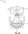
- Fig. 2B is a diagram of a second exemplary implementation of ultrasound probe 110 according to an implementation described herein.
- ultrasound probe 110 may include a 1D array of transducer elements coupled to a rotation motor.
- ultrasound probe 110 may include a base 210 connected to dome 118, a theta motor 220, a spindle 230, and a transducer bucket 270 with a 1D transducer array 275.
- Theta motor 220 and/or 1D transducer array 275 may include wired or wireless electrical connections that electrically connect theta motor 220 and/or 1D transducer array 275 to base unit 120 via cable 130 (not shown in Fig. 2B ).
- Base 210 may house theta motor 220 and provide structural support to ultrasound probe 110.
- Base 210 may connect to dome 118 and may form a seal with dome 118 to protect the components of ultrasound probe 110 from the external environment.
- Theta motor 220 may rotate spindle 230 with respect to base 210 in longitudinal direction with respect to 1D transducer array 275 by rotating around theta rotational plane 225.
- Spindle 230 may terminate in transducer bucket 270.
- 1D transducer array 275 may be mounted to transducer bucket 270.
- 1D transducer array 275 may include a curved or phased 1D array of piezoelectric transducers, capacitive transducers, and/or other types of ultrasound transducers.
- 1D transducer array 275 may convert electrical signals to ultrasound signals at a particular ultrasound frequency or range of ultrasound frequencies, may receive reflected ultrasound signals (e.g., echoes, etc.), and may convert the received ultrasound signals to electrical signals.
- One or more elements of 1D transducer array 275 may transmit and receive ultrasound signals in a particular direction of a set of directions, illustrated as item 276 in Fig. 2B .
- the elements of 1D transducer array 275 may generate ultrasound image data for a particular plane by electronically controlling the elements of 1D transducer array 275.
- 1D transducer array 275 may be controlled to tilt the ultrasound beam electronically in a phi direction, either by selectively firing a subset of transducers in 1D transducer array 275 or by controlling a firing delay between the individual transducer elements, resulting in 1D transducer array 275 to electronically sweep an ultrasound beam in an arc in either a forward or backward direction.
- the transducers of 1D transducer array 275 may be fired substantially simultaneously to obtain ultrasound image data for a plane in which 1D transducer array 275 is positioned.
- theta motor 220 may cycle through a set of planes one or more times to obtain a full 3D scan of an area of interest.
- 1D transducer array 275 may obtain ultrasound image data by controlling the transducers of 1D transducer array 275.
- the movement of theta motor 220 and the firing of 1D transducer array 275 may be interlaced in the 3D scan mode.
- the firing of 1D transducer array 275 may be followed by a movement of theta motor 220 from a first plane to a second plane, followed by the another firing of 1D transducer array 275, followed by movement of theta motor 220 from the second plane to a third plane, etc.
- Such interlaced movement may enable ultrasound probe 110 to obtain smooth continuous volume scanning as well as improve the rate at which the scan data is obtained.
- ultrasound probe 110 of Fig. 2B may be configured to enable continuous movement of theta motor 220.
- wiring from base 210 to 1D transducer array 275 may limit the movement of theta motor 220 in a particular direction.
- theta motor 220 may need to alternate rotating forward and backwards to move 1D transducer array 275 to particular scan planes to prevent binding or breaking of wires.
- the wiring may be replaced with an electrical connection that does not limit such movement of theta motor 220 and that enables theta motor 220 to continue to rotate in one direction.
- the wiring may be replaced with one or more conductive slip rings on spindle 230 and/or on shaft 235, and/or one or more wireless connections, as explained above with reference to Fig. 2A .
- Fig. 2C is a diagram of a third exemplary implementation of ultrasound probe 110 according to an implementation described herein.
- ultrasound probe 110 may be configured with spindle 230 positioned perpendicularly to shaft 235 and signal direction 265.
- the arrangement of ultrasound probe 110 shown in Fig. 2C may result in theta motor 220 moving the scan planes scanned by phi motor 240 in a rotational plane 225 around spindle 230.
- Fig. 2D is a diagram of a fourth exemplary implementation of ultrasound probe 110 according to an implementation described herein.
- ultrasound probe 110 may include transducer bucket 270 and 1D transducer array 275 with spindle 230 positioned perpendicularly to the center of set of directions 276.
- the arrangement of ultrasound probe 11 shown in Fig. 2D may result in theta motor 220 moving the scan planes scanned by 1D transducer array 275 in a rotational plane 225 around spindle 230.
- phi motor 240 rotates around a horizontal axis and theta motor 220 rotates around a vertical axis
- phi motor 240 rotates around a first horizontal axis
- theta motor 220 rotates around a second horizontal axis that is perpendicular to the first horizontal axis.
- Configurations of ultrasound probe 110 shown in Figs. 2C and 2D enable the execution of a fan scan by moving the scan planes scanned by phi motor 240 along a cylindrical curved surface, as compared with moving the scan planes within a plane (e.g., a horizontal plane) using the configuration of ultrasound probe 110 shown in Figs. 2A and 2B .
- a fan scan may be used when the patient's area of interest corresponds to a concave surface (e.g., the front of the neck, the flexing surface of a joint, the lower back, etc.) and/or when the target organ has an elongated shape (e.g., scanning the aorta, the large intestine, etc.).
- the interlaced scans described herein may also be implemented using the configurations of ultrasound probe 110 shown in Figs. 2C and 2D .
- ultrasound probe 110 may include fewer components, different components, additional components, or differently arranged components than depicted in Figs. 2A and 2B . Additionally or alternatively, one or more components of ultrasound probe 110 may perform one or more tasks described as being performed by one or more other components of ultrasound probe 110.
- Fig. 3 is a diagram illustrating example components of a device 300 according to an implementation described herein.
- Ultrasound probe 110 and/or base unit 120 may each include one or more devices 300.
- device 300 may include a bus 310, a processor 320, a memory 330, an input device 340, an output device 350, and a communication interface 360.
- Bus 310 may include a path that permits communication among the components of device 300.
- Processor 320 may include any type of single-core processor, multi-core processor, microprocessor, latch-based processor, and/or processing logic (or families of processors, microprocessors, and/or processing logics) that interprets and executes instructions.
- processor 320 may include an application-specific integrated circuit (ASIC), a field-programmable gate array (FPGA), and/or another type of integrated circuit or processing logic.
- ASIC application-specific integrated circuit
- FPGA field-programmable gate array
- Memory 330 may include any type of dynamic storage device that may store information and/or instructions, for execution by processor 320, and/or any type of nonvolatile storage device that may store information for use by processor 320.
- memory 330 may include a random access memory (RAM) or another type of dynamic storage device, a read-only memory (ROM) device or another type of static storage device, a content addressable memory (CAM), a magnetic and/or optical recording memory device and its corresponding drive (e.g., a hard disk drive, optical drive, etc.), and/or a removable form of memory, such as a flash memory.
- RAM random access memory
- ROM read-only memory
- CAM content addressable memory
- magnetic and/or optical recording memory device and its corresponding drive e.g., a hard disk drive, optical drive, etc.
- a removable form of memory such as a flash memory.
- Input device 340 may allow an operator to input information into device 300.
- Input device 340 may include, for example, a keyboard, a mouse, a pen, a microphone, a remote control, an audio capture device, an image and/or video capture device, a touch-screen display, and/or another type of input device.
- device 300 may be managed remotely and may not include input device 340. In other words, device 300 may be "headless" and may not include a keyboard, for example.
- Output device 350 may output information to an operator of device 300.
- Output device 350 may include a display, a printer, a speaker, and/or another type of output device.
- device 300 may include a display, which may include a liquid-crystal display (LCD) for displaying content to the customer.
- LCD liquid-crystal display
- device 300 may be managed remotely and may not include output device 350. In other words, device 300 may be "headless" and may not include a display, for example.
- Communication interface 360 may include a transceiver that enables device 300 to communicate with other devices and/or systems via wireless communications (e.g., radio frequency, infrared, and/or visual optics, etc.), wired communications (e.g., conductive wire, twisted pair cable, coaxial cable, transmission line, fiber optic cable, and/or waveguide, etc.), or a combination of wireless and wired communications.
- Communication interface 360 may include a transmitter that converts baseband signals to radio frequency (RF) signals and/or a receiver that converts RF signals to baseband signals.
- Communication interface 360 may be coupled to an antenna for transmitting and receiving RF signals.
- Communication interface 360 may include a logical component that includes input and/or output ports, input and/or output systems, and/or other input and output components that facilitate the transmission of data to other devices.
- communication interface 360 may include a network interface card (e.g., Ethernet card) for wired communications and/or a wireless network interface (e.g., a WiFi) card for wireless communications.
- Communication interface 360 may also include a universal serial bus (USB) port for communications over a cable, a Bluetooth TM wireless interface, a radio-frequency identification (RFID) interface, a near-field communications (NFC) wireless interface, and/or any other type of interface that converts data from one form to another form.
- USB universal serial bus
- device 300 may perform certain operations relating to performing an interlaced scan. Device 300 may perform these operations in response to processor 320 executing software instructions contained in a computer-readable medium, such as memory 330.
- a computer-readable medium may be defined as a non-transitory memory device.
- a memory device may be implemented within a single physical memory device or spread across multiple physical memory devices.
- the software instructions may be read into memory 330 from another computer-readable medium or from another device.
- the software instructions contained in memory 330 may cause processor 320 to perform processes described herein.
- hardwired circuitry may be used in place of, or in combination with, software instructions to implement processes described herein. Thus, implementations described herein are not limited to any specific combination of hardware circuitry and software.
- Fig. 3 shows exemplary components of device 300
- device 300 may include fewer components, different components, additional components, or differently arranged components than depicted in Fig. 3 . Additionally or alternatively, one or more components of device 300 may perform one or more tasks described as being performed by one or more other components of device 300.
- Fig. 4 is a diagram illustrating exemplary functional components of ultrasound system 100.
- the functional components of ultrasound system 100 may be implemented, for example, via processor 320 executing instructions from memory 330. Alternatively, some or all of the functional components of ultrasound system 100 may be implemented via hard-wired circuitry.
- ultrasound system 100 may include a user interface 410, an interlaced scan manager 420, a scanning order tables database (DB) 425, an image generator 430, and a data collector 450.
- DB scanning order tables database
- User interface 410 may generate a user interface (e.g., a graphical user interface) that displays ultrasound images to a user via display 122 and that is configured to receive selections and/or commands from the user via a touchscreen associated with display 122, via one or more control keys located on base unit 120 and/or on ultrasound probe 110, via a microphone included in base unit 120, and/or via another type of input method.
- a user may select a type of ultrasound image, an aiming mode via user interface 410, may select one or more aiming mode planes, and/or may select to perform a 3D scan once the user is satisfied with the position of ultrasound probe 110 during an aiming mode.
- Interlaced scan manager 420 may generate a 3D scan for an area of interest in a patient's body. For example, in response to a user selecting to perform the 3D scan, interlaced scan manager 420 may instruct image generator 430 to generate ultrasound images for a particular set of planes in a particular sequence with an interlaced movement of theta motor 220 and phi motor 240 based on information stored in scanning order tables DB 425. Scanning order tables DB 425 may store one or more scanning order tables.
- a particular scanning order table may include, for a particular number of planes and a particular interlacing factor k, information identifying a scanning order for a set of planes and a corresponding movement direction for theta motor 220 and phi motor 240 for each plane.
- a particular scanning order table may be selected by a user. In other implementations, a particular scanning order table may be selected based on one or more scan parameters. Exemplary scanning order tables are described below with reference to Figs. 6A, 6B, and 6C .
- interlaced scan manager 420 may be configured to enable a user to select, and then to perform, particular types of interlaced scans. For example, interlaced scan manager 420 may select and perform a continuous bi-plane scanning, to perform scanning with overlap of phi motor and theta motor movement (e.g., moving theta motor 220 from a first plane to a second pane while phi motor 240 is in the acceleration or deceleration region of its range of motion), to perform continuous theta motor movement in one direction, and/or other types of interlaced scans.
- phi motor e.g., moving theta motor 220 from a first plane to a second pane while phi motor 240 is in the acceleration or deceleration region of its range of motion
- Image generator 430 may generate ultrasound images in particular planes. For example, image generator 430 may instruct data collector to obtain a particular type of ultrasound image, to move to a particular plane (e.g., a particular position of theta motor 220), and to generate an ultrasound image of a particular type for the particular plane (e.g., using phi motor 240 and transducer 260).
- a particular plane e.g., a particular position of theta motor 220
- an ultrasound image of a particular type for the particular plane e.g., using phi motor 240 and transducer 260.
- Data collector 450 may be configured to collect ultrasound image data from ultrasound probe 110.
- Data collector 450 may include a phi motor controller 460, a theta motor controller 470, and a transducer controller 480.
- Phi motor controller 460 may control phi motor 240.
- Theta motor controller 470 may control theta motor 220.
- Transducer controller 480 may control transducer 260.
- ultrasound system 100 may include fewer components, different components, additional components, or differently arranged components than depicted in Fig. 4 . Additionally or alternatively, one or more components of ultrasound system 100 may perform one or more tasks described as being performed by one or more other components of ultrasound system 100.
- Fig. 5 is a flowchart of a process for interlaced scanning according to an implementation described herein.
- the process of Fig. 5 may be performed by ultrasound system 100.
- some or all of the process of Fig. 5 may be performed by another device or a group of devices separate from ultrasound system 100.
- the process of Fig. 5 may include defining a number of planes N, an interlacing factor k, and a permutation set ⁇ b 1 ,...,b k ⁇ of the set of integers ⁇ 1,...,k ⁇ (block 510).
- the interlacing factor k may determine the number of groups of scan planes and the permutation set may define a sequence in which the groups of scan planes are scanned.
- b i refers to the i-th group of scan planes.
- a user may select the number of planes N, the interlacing factor k, and the permutation set ⁇ b 1 ,...,b k ⁇ from a list of options displayed on display 122 when an interlacing scan is selected.
- ultrasound system 100 may automatically select a particular number of scan planes, interlacing factor, and/or permutation set based on one or more parameters associated with a scan to be performed, such as the area of interest, image size, type of ultrasound images selected, and/or another type of parameter.
- the variables may be initialized (block 520).
- the current index i may be set to 1
- the current theta motor direction d may be set to either forward or backward
- the current scan plane n may be set to b i if theta motor direction d is set to "forward”
- N-k+b i if theta motor direction d is set to "backward.
- a "forward" direction for theta motor 220 may be defined as moving along a circle in the direction of increasing plane numbers and a "backward” direction may be defined as moving along the circle in the direction of decreasing plane numbers.
- "forward" and “backward” directions for theta motor 220 may be defined differently.
- "forward" for theta motor 220 may be defined as counterclockwise and "backward” for theta motor 220 may be defined as clockwise.
- "forward" for phi motor 240 may be defined as moving along a plane from the position along the circle at which the plane is numbered and "backward” for phi motor 240 may be defined as moving along a plane toward the position along the circle at which the plane is numbered.
- “forward” and “backward” directions for phi motor 240 may be defined differently.
- "forward” for phi motor 240 may be defined as clockwise and "backward” for theta motor 220 may be defined as counterclockwise.
- the n-th plane may then be scanned (block 530).
- Transducer 260 or 1D transducer array 275 may perform a B-mode ultrasound scan, a P-mode ultrasound scan, a Doppler mode ultrasound scan, a harmonic mode ultrasound scan, and/or another type of ultrasound scan of the n-th plane.
- the n-th plane may be scanned by moving phi motor 240 in a direction that is opposite to the direction phi motor 240 moved in when scanning the previous plane.
- phi motor 240 may move in a forward direction for the previous plane, and if phi motor 240 moved in a backward direction for the previous plane, phi motor 240 may move in a forward direction.
- phi motor 240 may move in a default first direction (e.g., forward in some implementation, backward in other implementations, etc.).
- the n-th plane may be scanned by electronically controlling the transducers of 1D transducer array 275 to scan the n-the by firing the transducers in a particular sequence.
- the transducers of 1D transducer array 275 may be fired without a time delay by firing the transducers substantially simultaneously or in a random order.
- Theta motor 220 may then be moved to the n-th scan plane (block 590) and processing may return to block 530 to scan the n-th scan plane by moving phi motor 240 in the direction that is opposite to the last direction phi motor 240 moved in (or by electronically controlling 1D transducer array 275 to scan the n-th plane).
- processing may proceed to block 590 to move the theta motor 220 to the n-th scan plane and processing may return to block 530 to scan the n-th scan plane by moving phi motor 240 in the direction that is opposite to the last direction phi motor 240 moved in (or by electronically controlling 1D transducer array 275 to scan the n-th plane).
- n may be set to n - k (block 555). In other words, the current scan plane may be decreased by the interlacing factor. A determination may be made as to whether n is set to less than 1 (block 565). If n ⁇ 1 (block 565 - YES), the current index i may be set to mod(i,k)+1 and n may be set to b i (block 575), and the theta motor direction may be set to forward (block 585).
- Theta motor 220 may then be moved to the n-th scan plane (block 590) and processing may return to block 530 to scan the n-th scan plane by moving phi motor 240 in the direction that is opposite to the last direction phi motor 240 moved in (or by electronically controlling 1D transducer array 275 to scan the n-th plane).
- processing may proceed to block 590 to move the theta motor 220 to the n-th scan plane and processing may return to block 530 to scan the n-th scan plane by moving phi motor 240 in the direction that is opposite to the last direction phi motor 240 moved in (or by electronically controlling 1D transducer array 275 to scan the n-th plane).
- the process of Fig. 5 may continue until a user selects to stop performing volume scan, until a selected number of volume scans have been performed, and/or until a different type of trigger condition is satisfied.
- Figs. 6A, 6B, 6C , and 6D are diagrams of exemplary scanning order tables.
- Fig. 6A illustrates a scanning order table 601 for an interlacing scan with 12 planes and an interlacing factor k of 2.
- Scanning order table 601 may include a scanning order row 610, a plane number row 620, a phi motor direction row 630, and a theta motor direction row 640.
- Scanning order row 610 may include information identifying the order in which the planes are scanned.
- Plane number row 620 may include information identifying the plane number based on a sequential numbering of the planes from a starting plane around a circle (see, for example, Fig. 7A ).
- Phi motor direction row 630 may include information identifying the movement direction of phi motor 240 for each plane ("FW" corresponds to forward motion with respect to the plane numbering and "BW" corresponds to backward motion with respect to the plane numbering).
- Theta motor direction row 640 may include information identifying the movement direction of theta motor 220 for each group of planes.
- the scanning order of the planes for one volume scan for an interlacing scan for 12 planes and an interlacing factor of 2, and a permutation set of ⁇ 1,2 ⁇ is 1, 3, 5, 7, 9, 11, followed by 12, 10, 8, 6, 4, 2.
- the direction of phi motor 240 changes with each plane and the direction of theta motor 220 changes with each group of planes. Since the interlacing factor is 2, the number of groups of planes is 2.
- Fig. 6B illustrates a scanning order table 602 for an interlacing scan with 12 planes, an interlacing factor k of 4, and a permutation set of ⁇ 1,2,3,4 ⁇ .
- the scanning order of the planes for one volume scan for an interlacing scan for 12 planes and an interlacing factor of 4 is 1, 5, 9, followed by 10, 6, 2, followed by 3, 7, 11, and followed by 12, 8, 4.
- the direction of phi motor 240 changes with each plane and the direction of theta motor 220 changes with each group of planes. Since the interlacing factor is 4, the number of groups of planes is 4.
- Fig. 6C illustrates a scanning order table 603 for another interlacing scan with 12 planes and an interlacing factor k of 4, and a permuation set of ⁇ 3, 2, 4, 1 ⁇ .
- the scanning order for scanning order table 603 for one volume scan is 3, 7, 11, followed by 10, 6, 2, followed by 4, 8, 12, followed by 9, 5, 1.
- Scanning order table 603 differs from scanning order table 602 by having a different permutation set.
- Fig. 6D illustrates a scanning order table 604 for an interlacing scan with 12 planes an interlacing factor k of 2, and a permutation set of ⁇ 2, 1 ⁇ .
- the scanning order for scanning order table 604 is 11, 9, 7, 5, 3, 1, followed by 2, 4, 6, 8, 10, and 12.
- Scanning order table 604 differs from scanning order table 601 by having a different permutation set and illustrates that theta motor direction row 640 does not need to start with a "forward" direction.
- Figs. 7A , 7B , 7C , and 7D are diagrams of exemplary ultrasound transducer trajectories for volume scans based on 12 planes.
- Fig. 7A illustrates a trajectory 701 of ultrasound transducer 260 for an interlaced scan based on 12 planes and an interlacing factor of one for a first volume scan 710 and a second volume scan 712.
- Fig. 7A identifies phi motor movement 714 for plane 9 to demonstrate that phi motor 240 moves across particular planes and theta motor movement 716 from plane 2 to plane 3 to demonstrate that theta motor 220 moves from plane to plane.
- Fig. 7B illustrates a trajectory 702 of ultrasound transducer 260 for an interlaced scan based on 12 planes and an interlacing factor of two for first volume scan (items 720 and 722) and a second volume scan (items 724 and 726).
- Fig. 7C illustrates a trajectory 703 of ultrasound transducer for an interlaced scan based on 12 planes and an interlacing factor of 3 for first volume scan (items 730, 731, and 732) and a second volume scan (items 733, 734, and 735).
- Fig. 7B illustrates a trajectory 702 of ultrasound transducer 260 for an interlaced scan based on 12 planes and an interlacing factor of two for first volume scan (items 720 and 722) and a second volume scan (items 724 and 726).
- Fig. 7C illustrates a trajectory 703 of ultrasound transducer for an interlaced scan based on 12 planes and an interlacing factor of 3
- FIG. 7D illustrates a trajectory 704 of ultrasound transducer for an interlaced scan based on 12 planes and an interlacing factor of four for first volume scan (items 740, 741, 742, and 743) and a second volume scan (items 744, 745, 746, and 747).
- Figs. 8A , 8B , 8C , and 8D are diagrams of exemplary ultrasound transducer trajectories for volume scans based on 24 planes.
- Fig. 8A illustrates a trajectory 801 of ultrasound transducer 260 for an interlaced scan based on 24 planes and an interlacing factor of one for a first volume scan 810 and a second volume scan 812.
- Fig. 8B illustrates a trajectory 802 of ultrasound transducer 260 for an interlaced scan based on 24 planes and an interlacing factor of two for a first volume scan (items 820 and 822) and a second volume scan (items 824 and 826).
- Fig. 8A illustrates a trajectory 801 of ultrasound transducer 260 for an interlaced scan based on 24 planes and an interlacing factor of one for a first volume scan 810 and a second volume scan 812.
- Fig. 8B illustrates a trajectory 802 of ultrasound transducer 260 for
- FIG. 8C illustrates a trajectory 803 of ultrasound transducer for an interlaced scan based on 24 planes and an interlacing factor of 3 for first volume scan (items 830, 831, and 832) and a second volume scan (items 833, 834, and 835).
- Fig. 8D illustrates a trajectory 804 of ultrasound transducer for an interlaced scan based on 24 planes and an interlacing factor of 4 for first volume scan (items 840, 841, 842, and 843) and a second volume scan (items 844, 845, 846, and 847).
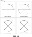
- Figs. 9A and 9B are diagrams of exemplary ultrasound transducer trajectories for volume scans based on four planes.
- Fig. 9A illustrates a trajectory 901 of ultrasound transducer 260 for an interlaced scan based on four planes and an interlacing factor of one for a first volume scan 910 and a second volume scan 912.
- Fig. 9B illustrates a trajectory 902 of ultrasound transducer 260 for an interlaced scan based on four planes and an interlacing factor of two for first volume scan (items 920 and 922) and a second volume scan (items 924 and 926).
- Figs. 10A and 10B are diagrams of exemplary ultrasound transducer trajectories for volume scans based on two planes.
- Fig. 10A illustrates a trajectory 1001 of ultrasound transducer 260 for an interlaced scan based on two planes and an interlacing factor of one for first bi-plane scan 1010 and a second bi-plane scan 1012.
- Fig. 10B illustrates a trajectory 1002 of ultrasound transducer 260 for an interlaced scan based on two planes and an interlacing factor of two for first bi-plane scan (items 1020 and 1022) and a second bi-plane scan (items 1024 and 1026).
- An interlaced scan based on 2 planes and an interlacing factor of two corresponds to the case of continuous bi-plane scanning.
- Fig. 11 illustrates a continuous bi-plane scanning trajectory 1100.
- ultrasound transducer 260 may collect two orthogonal ultrasound images (e.g., B-mode images). If the speed of phi motor 240 and theta motor 220 is sufficiently fast, continuous bi-plane scanning may be used for real-time, or near real-time, bi-plane ultrasound imaging. Continuous bi-plane scanning may be useful, for example, for obtaining a real-time transverse and longitudinal view of an area of interest in a patient's body.
- Figs. 7A , 7B , 7C , and 7D ; 8A , 8B , 8C , and 8D ; 9A and 9B ; 10A and 10B ; and 11 illustrate ultrasound transducer trajectories for volume scans using ultrasound probe 110 of Fig. 2A , which includes movement of theta motor 220 and phi motor 240.
- the illustrated ultrasound transducer trajectories may also be applied for volume scans using ultrasound probe 110 of Fig. 2B with theta motor 220 and 1D transducer array 275, if phi motor movement 714 is replaced with an electronically controlled scan using 1D transducer array 275, which does not include any physical motor movement but rather represents the particular plane being scanned.
- the arrows representing the direction of phi motor movement 714 in each plane may be ignored.
- Fig. 12 is a diagram 1200 of the range of motion of phi motor 240.
- a range of motion 1210 for phi motor 240 may include a sector of a circle.
- range of motion 1210 may span less than 180°, such as approximately 150°.
- Range of motion 1210 may include two acceleration/deceleration regions 1220 and a constant speed region 1230.
- constant speed region 1230 may span approximately 120°.
- Ultrasound transducer 260 may then initiate scanning the plane and may continue to scan the plane as phi motor 240 moves across constant speed region 1230.
- Ultrasound transducer 260 may stop scanning at the end of constant speed region 1230 and phi motor 240 may start to decelerate, reaching a stationary position at the end of acceleration/deceleration region 1220, which also corresponds to the end of range of motion 1210.
- phi motor 240 may scan a sector corresponding to constant speed region 1230 and resulting in an ultrasound image with a viewing angle corresponding to the angle of constant speed region 1230 (e.g., 120°).
- a volume scan speed may be improved by taking advantage of the time phi motor 240 is moving through one of the acceleration/deceleration regions 1220 by moving theta motor 220 from a previous plane (during acceleration) or to a next plane (during deceleration) of the interlaced scan.
- the movement of theta motor 220 and phi motor 240 may overlap.
- Fig. 13A is a diagram 1301 illustrating the motion trajectories and positions of motors for a two plane volume scan without overlap and with overlap.
- a motion trajectory without overlap 1310 results in motion profile without overlap 1315, which is shown in Fig. 13A for five consecutive volume scans.
- a motion trajectory with overlap 1320 which results in motion profile with overlap 1325, also shown for five consecutive volume scans.
- theta motor 220 starts to move to the next plane while phi motor 240 is decelerating and phi motor 240 starts to accelerate for the scan of the next plane while theta motor 220 is still moving and before theta motor 220 completes the movement to the next plane.
- Motion profile with overlap 1325 illustrates that in this exemplary interlaced scan, overlap yields a time savings of, for example, greater than 0.2 seconds for five volume scans, resulting in faster volume scans closer to real-time and reduced motion blur.
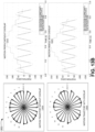
- Fig. 13B is a diagram illustrating the motion trajectories and positions of motors for a 12 plane volume scan without overlap and with overlap.
- a motion trajectory without overlap 1350 results in motion profile without overlap 1355, which is shown in Fig. 13B for one volume scan.
- a motion trajectory with overlap 1360 which results in motion profile with overlap 1365, also shown for one volume scan.
- Motion profile with overlap 1365 illustrates that in this exemplary interlaced scan with 12 scan planes, overlap yields a time savings of, for example, greater than 0.2 seconds for a single volume scan.
- ultrasound probe 110 may be configured to enable continuous motion of theta motor 220 in one direction.
- Continuous motion of theta motor 220 may be enabled by, for example, replacing wiring to ultrasound transducer 260 with a conductive slip ring and/or a wireless connection.
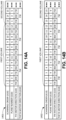
- Figs. 14A and 14B are diagrams of exemplary scanning order tables with continuous theta motor movement.
- the rules for an interlaced scan may be replaced with the following rules: the direction of phi motor 240 changed with every plane during a volume scan and the direction of theta motor 220 does not change.
- Fig. 14A illustrates a scanning order table 1401 for an interlacing scan with 12 planes, an interlacing factor k of 2, and continuous motion of theta motor 220.
- the direction of phi motor 240 changes with each plane and the direction of theta motor 220 does not change.
- Fig. 14B illustrates a scanning order table 1402 for an interlacing scan with 12 planes, an interlacing factor k of four, and continuous motion of theta motor 220.
- the direction of phi motor 240 changes with each plane and the direction of theta motor 220 does not change.
- Figs. 15A , 15B , and 15C are diagrams of exemplary ultrasound transducer trajectories for volume scans based on 12 planes with continuous theta motor movement.
- Fig. 15A illustrates a trajectory 1501 of ultrasound transducer 260 for an interlaced scan based on 12 planes and an interlacing factor of two for first volume scan (items 1510 and 1512) and a second volume scan (items 1514 and 1516).
- Fig. 15A illustrates a trajectory 1501 of ultrasound transducer 260 for an interlaced scan based on 12 planes and an interlacing factor of two for first volume scan (items 1510 and 1512) and a second volume scan (items 1514 and 1516).
- FIG. 15B illustrates a trajectory 1502 of ultrasound transducer for an interlaced scan based on two planes and an interlacing factor of two (i.e., a bi-plane scan) for first volume scan (items 1520 and 1521), a second volume scan (items 1522 and 1523), and a third volume scan (items 1524 and 1525).
- Fig. 15C illustrates a diagram 1503 comparing trajectories of ultrasound transducer 260 for continuous bi-plane scanning with continuous theta motor movement without overlap (1530) and with overlap (item 1535).
- embodiments described above refer to scanning a bladder, other organs, joints, vessels, and/or body areas, such as an aorta, prostate, kidney, uterus, ovaries, heart, etc., could scanned and/or imaged in other implementations.
- selection of the number of planes and/or the interlacing factor may be automatic based on a size of an image, the area of interest, and/or another parameter.
- a component may include hardware, such as a processor, an ASIC, or a FPGA, or a combination of hardware and software (e.g., a processor executing software).
- logic may refer to a combination of one or more processors configured to execute instructions stored in one or more memory devices, may refer to hardwired circuitry, and/or may refer to a combination thereof. Furthermore, a logic may be included in a single device or may be distributed across multiple, and possibly remote, devices.
- the term “substantially” is utilized herein to represent the inherent degree of uncertainty that may be attributed to any quantitative comparison, value, measurement, or other representation.
- the term “substantially” is also utilized herein to represent the degree by which a quantitative representation may vary from a stated reference without resulting in a change in the basic function of the subject matter at issue.
Landscapes
- Health & Medical Sciences (AREA)
- Life Sciences & Earth Sciences (AREA)
- Engineering & Computer Science (AREA)
- Medical Informatics (AREA)
- Surgery (AREA)
- Pathology (AREA)
- Radiology & Medical Imaging (AREA)
- Biophysics (AREA)
- Biomedical Technology (AREA)
- Heart & Thoracic Surgery (AREA)
- Physics & Mathematics (AREA)
- Molecular Biology (AREA)
- Nuclear Medicine, Radiotherapy & Molecular Imaging (AREA)
- Animal Behavior & Ethology (AREA)
- General Health & Medical Sciences (AREA)
- Public Health (AREA)
- Veterinary Medicine (AREA)
- Computer Vision & Pattern Recognition (AREA)
- Computer Networks & Wireless Communication (AREA)
- Vascular Medicine (AREA)
- Ultra Sonic Daignosis Equipment (AREA)
Claims (15)
- Procédé réalisé par un dispositif (100), le procédé étant caractérisé en ce qu'il comprend :la sélection, au moyen du dispositif (100), d'un certain nombre de plans de balayage pour un balayage entrelacé afin de balayer un volume d'une zone d'intérêt dans le corps d'un patient à l'aide d'un transducteur à ultrasons (260) ;la sélection, par le dispositif (100), d'un facteur d'entrelacement pour le balayage entrelacé ;la division, par le dispositif (100), des plans de balayage en groupes de plans de balayage sur la base du facteur d'entrelacement ; etla réalisation, par le dispositif (100), du balayage entrelacé en commandant un premier moteur (240) configuré pour faire tourner le transducteur à ultrasons (260) autour d'un axe horizontal pour balayer un plan et un second moteur (220) configuré pour faire tourner le transducteur à ultrasons (260) autour d'un axe vertical pour se déplacer vers un plan différent, et dans lequel le premier moteur (240) se déplace dans une première direction pour au moins certains des plans de balayage et dans une deuxième direction, opposée à la première direction, pour d'autres des plans de balayage.
- Procédé selon la revendication 1, dans lequel le second moteur (220) se déplace dans une troisième direction pour au moins certains des groupes de plans de balayage et dans une quatrième direction, opposée à la troisième direction, pour d'autres des groupes de plans de balayage.
- Procédé selon la revendication 1, dans lequel le premier moteur (240) change de direction à chaque plan et dans lequel le second moteur (220) change de direction à chaque groupe sans changer de direction au sein d'un groupe.
- Procédé selon la revendication 1, dans lequel les plans de balayage sont séparés d'un angle correspondant à cent quatre-vingts degrés divisé par le nombre de plans de balayage.
- Procédé selon la revendication 1, dans lequel la division des plans de balayage en groupes de plans de balayage sur la base du facteur d'entrelacement comprend :la numérotation séquentielle des plans de balayage ;la division des plans de balayage en un certain nombre de groupes de plans de balayage correspondant au facteur d'entrelacement ; etla distribution séquentielle des plans de balayage numérotés dans les groupes de plans de balayage.
- Procédé selon la revendication 1, dans lequel la réalisation du balayage entrelacé comprend :le balayage d'un plan particulier en déplaçant le premier moteur (240) dans une direction qui est opposée à une direction dans laquelle le premier moteur (240) s'est déplacé lors du balayage d'un plan précédent ;le déplacement vers un plan suivant en déplaçant le second moteur (220) d'un certain nombre de plans correspondant au facteur d'entrelacement, dans lequel la direction du second moteur (220) change si le plan suivant se trouve dans un autre des groupes de plans de balayage que le plan précédent.
- Procédé selon la revendication 1, dans lequel le nombre de plans de balayage correspond à deux, dans lequel le facteur d'entrelacement correspond à deux, et dans lequel la réalisation du balayage entrelacé comprend :
la réalisation d'un balayage biplan continu. - Procédé selon la revendication 1, dans lequel une plage de mouvement du premier moteur (240) comprend une région d'accélération ou de décélération et une région de vitesse constante, et dans lequel la réalisation du balayage entrelacé comprend :
la commande de la rotation du second moteur (220) pendant que le premier moteur (240) se trouve dans la région d'accélération ou de décélération de la plage de mouvement. - Procédé selon la revendication 1, dans lequel le second moteur (220) se déplace dans une même direction pour tous les groupes de plans de balayage.
- Procédé selon la revendication 1, dans lequel la réalisation du balayage entrelacé comprend :la réalisation d'un premier balayage de volume avec le second moteur (220) démarrant dans un premier plan ; etla réalisation d'un second balayage de volume avec le second moteur (220) démarrant dans un second plan, dans lequel le second plan est différent du premier plan.
- Système (100) comprenant :
une sonde à ultrasons (110) comprenant :un transducteur à ultrasons (260) ; etune unité de dispositif de commande (120) ;
caractérisé en ce que la sonde à ultrasons (110) comprend également :un premier moteur (240) configuré pour faire tourner le transducteur à ultrasons (260) autour d'un axe horizontal pour balayer un plan ; etun second moteur (220) configuré pour faire tourner le transducteur à ultrasons (260) autour d'un axe vertical, ou autour d'un autre axe horizontal perpendiculaire à l'axe horizontal du premier moteur (240), pour se déplacer vers un plan différent ;et dans lequel l'unité de dispositif de commande (120) est configurée pour :sélectionner un certain nombre de plans de balayage pour un balayage entrelacé afin de balayer un volume d'une zone d'intérêt dans le corps d'un patient à l'aide de la sonde à ultrasons ;sélectionner un facteur d'entrelacement pour le balayage d'entrelacement ;diviser les plans de balayage en groupes de plans de balayage sur la base du facteur d'entrelacement ; etréaliser le balayage entrelacé en commandant le premier moteur (240) et le second moteur (220), et dans lequel le premier moteur (240) se déplace dans une première direction pour au moins certains des plans de balayage et dans une deuxième direction, opposée à la première direction, pour d'autres des plans de balayage. - Système (100) selon la revendication 11, dans lequel le premier moteur (240) change de direction à chaque plan et dans lequel le second moteur (220) change de direction à chaque groupe sans changer de direction au sein d'un groupe.
- Système (100) selon la revendication 11, dans lequel, lors de la réalisation du balayage entrelacé, l'unité de dispositif de commande est en outre configurée pour :balayer un plan particulier en déplaçant le premier moteur (240) dans une direction qui est opposée à une direction dans laquelle le premier moteur (240) s'est déplacé lors du balayage d'un plan précédent ;déplacer vers un plan suivant en déplaçant le second moteur (220) d'un certain nombre de plans correspondant au facteur d'entrelacement, dans lequel la direction du second moteur (220) change si le plan suivant se trouve dans un autre des groupes de plans de balayage que le plan précédent.
- Système (100) selon la revendication 11, dans lequel le nombre de plans de balayage correspond à deux, dans lequel le facteur d'entrelacement correspond à deux, et dans lequel, lors de la réalisation du balayage entrelacé, l'unité de dispositif de commande est en outre configurée pour :
réaliser un balayage biplan continu. - Système (100) selon la revendication 11, dans lequel une plage de mouvement du premier moteur (240) comprend une région d'accélération ou de décélération et une région de vitesse constante, et dans lequel, lors de la réalisation du balayage entrelacé, l'unité de dispositif de commande est en outre configurée pour :
commander la rotation du second moteur (220) pendant que le premier moteur (240) se trouve dans la région d'accélération ou de décélération de la plage de mouvement.
Applications Claiming Priority (2)
| Application Number | Priority Date | Filing Date | Title |
|---|---|---|---|
| US201862642193P | 2018-03-13 | 2018-03-13 | |
| PCT/US2019/019800 WO2019177773A1 (fr) | 2018-03-13 | 2019-02-27 | Balayage entrelacé généralisé au moyen d'une sonde ultrasonore |
Publications (3)
| Publication Number | Publication Date |
|---|---|
| EP3764910A1 EP3764910A1 (fr) | 2021-01-20 |
| EP3764910C0 EP3764910C0 (fr) | 2023-11-15 |
| EP3764910B1 true EP3764910B1 (fr) | 2023-11-15 |
Family
ID=66102177
Family Applications (1)
| Application Number | Title | Priority Date | Filing Date |
|---|---|---|---|
| EP19716600.2A Active EP3764910B1 (fr) | 2018-03-13 | 2019-02-27 | Balayage entrelacé généralisé au moyen d'une sonde ultrasonore |
Country Status (7)
| Country | Link |
|---|---|
| US (1) | US11564656B2 (fr) |
| EP (1) | EP3764910B1 (fr) |
| JP (1) | JP7043622B2 (fr) |
| KR (1) | KR102493717B1 (fr) |
| CN (1) | CN111885960B (fr) |
| CA (1) | CA3092799C (fr) |
| WO (1) | WO2019177773A1 (fr) |
Families Citing this family (1)
| Publication number | Priority date | Publication date | Assignee | Title |
|---|---|---|---|---|
| CN114025281B (zh) * | 2021-09-24 | 2025-01-24 | 中国船舶重工集团公司第七一五研究所 | 一种全空间扫描式圆环换能器结构 |
Family Cites Families (63)
| Publication number | Priority date | Publication date | Assignee | Title |
|---|---|---|---|---|
| US3509341A (en) * | 1966-06-01 | 1970-04-28 | Picker Corp | Multiple detector radiation scanning device |
| US4034744A (en) * | 1975-11-13 | 1977-07-12 | Smith Kline Instruments, Inc. | Ultrasonic scanning system with video recorder |
| JPS54112587A (en) | 1978-02-23 | 1979-09-03 | Tokyo Shibaura Electric Co | Ultrasonic wave diagnosis device |
| JPS54128187A (en) * | 1978-03-29 | 1979-10-04 | Tokyo Shibaura Electric Co | Ultrasonic wave reflection device |
| US4271706A (en) | 1978-05-03 | 1981-06-09 | Georgetown University | Ultrasonic scanner |
| US4375818A (en) | 1979-03-12 | 1983-03-08 | Olympus Optical Company Ltd. | Ultrasonic diagnosis system assembled into endoscope |
| NL7905405A (nl) | 1979-07-11 | 1981-01-13 | Philips Nv | Televisieschakeling voor het veranderen van een interlinieeringsverhouding. |
| US4341120A (en) | 1979-11-09 | 1982-07-27 | Diasonics Cardio/Imaging, Inc. | Ultrasonic volume measuring system |
| JPS56128147A (en) * | 1980-03-12 | 1981-10-07 | Fujitsu Ltd | Ultrasonic probe |
| US4637256A (en) | 1983-06-23 | 1987-01-20 | Matsushita Electric Industrial Co., Ltd. | Ultrasonic probe having dual-motion transducer |
| DE3778179D1 (de) | 1986-01-30 | 1992-05-21 | Matsushita Electric Industrial Co Ltd | Ultraschallwandler fuer medizinische diagnostik. |
| US4841979A (en) | 1988-01-25 | 1989-06-27 | Capistrano Labs, Inc. | Ultrasonic prostate probe assembly |
| DE69027284T2 (de) | 1989-12-14 | 1996-12-05 | Aloka Co Ltd | Dreidimensionaler Ultraschallabtaster |
| JPH03215252A (ja) * | 1990-01-22 | 1991-09-20 | Toshiba Corp | メカニカル超音波診断装置 |
| US5181514A (en) | 1991-05-21 | 1993-01-26 | Hewlett-Packard Company | Transducer positioning system |
| CA2110148C (fr) | 1992-12-24 | 1999-10-05 | Aaron Fenster | Systeme d'echographie tridimensionnelle |
| US5589870A (en) * | 1994-10-31 | 1996-12-31 | Xerox Corporation | Spot profile control using fractional interlace factors in a polygon ROS |
| US5487388A (en) | 1994-11-01 | 1996-01-30 | Interspec. Inc. | Three dimensional ultrasonic scanning devices and techniques |
| US5740804A (en) * | 1996-10-18 | 1998-04-21 | Esaote, S.P.A | Multipanoramic ultrasonic probe |
| US6080108A (en) | 1998-11-17 | 2000-06-27 | Atl Ultrasound, Inc. | Scanning aid for quantified three dimensional ultrasonic diagnostic imaging |
| JP3696000B2 (ja) | 1999-08-04 | 2005-09-14 | オリンパス株式会社 | 超音波プローブ |
| JP2001149372A (ja) | 1999-11-26 | 2001-06-05 | Matsushita Electric Ind Co Ltd | 超音波探触子 |
| US6709394B2 (en) * | 2000-08-17 | 2004-03-23 | Koninklijke Philips Electronics N.V. | Biplane ultrasonic imaging |
| US6544175B1 (en) | 2000-09-15 | 2003-04-08 | Koninklijke Philips Electronics N.V. | Ultrasound apparatus and methods for display of a volume using interlaced data |
| US7556602B2 (en) * | 2000-11-24 | 2009-07-07 | U-Systems, Inc. | Breast cancer screening with adjunctive ultrasound mammography |
| US6780153B2 (en) | 2001-06-25 | 2004-08-24 | Angelsen Bjoern A. J. | Mechanism and system for 3-dimensional scanning of an ultrasound beam |
| US8137279B2 (en) | 2001-10-16 | 2012-03-20 | Envisioneering, Llc | Scanning probe |
| US6709397B2 (en) | 2001-10-16 | 2004-03-23 | Envisioneering, L.L.C. | Scanning probe |
| US7128711B2 (en) | 2002-03-25 | 2006-10-31 | Insightec, Ltd. | Positioning systems and methods for guided ultrasound therapy systems |
| US7520857B2 (en) * | 2002-06-07 | 2009-04-21 | Verathon Inc. | 3D ultrasound-based instrument for non-invasive measurement of amniotic fluid volume |
| US7744534B2 (en) * | 2002-06-07 | 2010-06-29 | Verathon Inc. | 3D ultrasound-based instrument for non-invasive measurement of amniotic fluid volume |
| US6733457B2 (en) | 2002-06-11 | 2004-05-11 | Vermon | Motorized multiplane transducer tip apparatus with transducer locking |
| US6905468B2 (en) | 2002-09-18 | 2005-06-14 | Diagnostic Ultrasound Corporation | Three-dimensional system for abdominal aortic aneurysm evaluation |
| US7280435B2 (en) * | 2003-03-06 | 2007-10-09 | General Electric Company | Switching circuitry for reconfigurable arrays of sensor elements |
| JP2005040204A (ja) | 2003-07-23 | 2005-02-17 | Olympus Corp | 超音波内視鏡装置 |
| US20070088213A1 (en) * | 2003-11-20 | 2007-04-19 | Koninklijke Philips Electronics N.V. | Ultrasonic diagnostic imaging with automatic adjustment of beamforming parameters |
| CN1882982A (zh) * | 2003-11-21 | 2006-12-20 | 皇家飞利浦电子股份有限公司 | 使用具有波束扫描反转的机械探针的三维超声波成像 |
| JP2007020908A (ja) * | 2005-07-19 | 2007-02-01 | Toshiba Corp | 超音波診断装置及び超音波診断装置の制御プログラム |
| KR100763453B1 (ko) | 2006-01-09 | 2007-10-08 | (주) 엠큐브테크놀로지 | 방광 진단용 초음파 진단 장치 및 초음파 진단 방법 |
| US8652047B2 (en) * | 2006-01-09 | 2014-02-18 | Mcube Technology Co., Ltd. | Apparatus and method for automatically measuring the volume of urine in a bladder using ultrasound signals |
| US20110137172A1 (en) | 2006-04-25 | 2011-06-09 | Mcube Technology Co., Ltd. | Apparatus and method for measuring an amount of urine in a bladder |
| KR100779548B1 (ko) * | 2006-04-25 | 2007-11-27 | (주) 엠큐브테크놀로지 | 방광 진단용 초음파 진단 장치 및 초음파 진단 방법 |
| US20140024937A1 (en) | 2006-04-25 | 2014-01-23 | Mcube Technology Co., Ltd. | Apparatus and method for measuring an amount of urine in a bladder |
| US8147414B2 (en) * | 2006-10-12 | 2012-04-03 | Innoscion, Llc | Image guided catheter having remotely controlled surfaces-mounted and internal ultrasound transducers |
| US8167803B2 (en) * | 2007-05-16 | 2012-05-01 | Verathon Inc. | System and method for bladder detection using harmonic imaging |
| JP5095304B2 (ja) * | 2007-08-21 | 2012-12-12 | 株式会社東芝 | 超音波診断装置 |
| US20160192904A1 (en) | 2008-03-10 | 2016-07-07 | Mcube Technology Co., Ltd. | Apparatus and method for measuring an amount of urine in a bladder |
| JP5658151B2 (ja) * | 2008-08-07 | 2015-01-21 | ベラソン インコーポレイテッドVerathon Inc. | 腹部大動脈瘤の直径を測定するための装置、システム、方法 |
| WO2011085135A1 (fr) * | 2010-01-07 | 2011-07-14 | Verathon Inc. | Dispositif, système et procédé d'accès à un vaisseau sanguin |
| JP5649083B2 (ja) * | 2010-07-14 | 2015-01-07 | 株式会社日立メディコ | 超音波画像の画像復元方法およびその装置並びに超音波診断装置 |
| JP5688197B2 (ja) * | 2010-08-31 | 2015-03-25 | ビー−ケー メディカル エーピーエス | 2次元超音波画像の3次元表示 |
| US9668716B2 (en) * | 2010-12-10 | 2017-06-06 | General Electric Company | Ultrasound imaging system and method for ultrasound imaging a three dimensional volume |
| CN102579071B (zh) * | 2011-01-14 | 2015-11-25 | 深圳迈瑞生物医疗电子股份有限公司 | 一种三维超声成像的方法及系统 |
| EP2781192A4 (fr) * | 2011-11-17 | 2015-08-12 | Hitachi Aloka Medical Ltd | Dispositif de diagnostic échographique et procédé de génération d'image échographique |
| JP6139184B2 (ja) * | 2012-04-05 | 2017-05-31 | 東芝メディカルシステムズ株式会社 | 超音波診断装置及び制御方法 |
| US9924923B2 (en) * | 2012-06-13 | 2018-03-27 | University Of Virginia Patent Foundation | Ultrasound imaging of specular-reflecting target |
| AU2013329043B2 (en) * | 2012-10-12 | 2018-01-18 | Muffin Incorporated | Devices and methods for three-dimensional internal ultrasound usage |
| WO2014107427A1 (fr) | 2013-01-04 | 2014-07-10 | Muffin Incorporated | Dispositif ultrasonore à mouvement alternatif |
| JP5800324B2 (ja) * | 2013-01-22 | 2015-10-28 | 富士フイルム株式会社 | 超音波診断装置、超音波画像生成方法およびプログラム |
| JP2014221119A (ja) | 2013-05-13 | 2014-11-27 | 株式会社東芝 | 超音波診断装置及び制御プログラム |
| JP6363229B2 (ja) * | 2014-02-05 | 2018-07-25 | ベラソン インコーポレイテッドVerathon Inc. | 超音波データ収集 |
| JP2016016022A (ja) * | 2014-07-04 | 2016-02-01 | 株式会社東芝 | 超音波診断装置 |
| CN109219394B (zh) * | 2016-03-21 | 2023-02-03 | 伊索诺健康公司 | 可穿戴式超声系统及方法 |
-
2019
- 2019-02-27 KR KR1020207029235A patent/KR102493717B1/ko active Active
- 2019-02-27 EP EP19716600.2A patent/EP3764910B1/fr active Active
- 2019-02-27 WO PCT/US2019/019800 patent/WO2019177773A1/fr not_active Ceased
- 2019-02-27 CA CA3092799A patent/CA3092799C/fr active Active
- 2019-02-27 JP JP2020548660A patent/JP7043622B2/ja active Active
- 2019-02-27 US US16/287,118 patent/US11564656B2/en active Active
- 2019-02-27 CN CN201980018637.4A patent/CN111885960B/zh active Active
Also Published As
| Publication number | Publication date |
|---|---|
| KR102493717B1 (ko) | 2023-01-30 |
| JP2021517036A (ja) | 2021-07-15 |
| US11564656B2 (en) | 2023-01-31 |
| EP3764910C0 (fr) | 2023-11-15 |
| CN111885960A (zh) | 2020-11-03 |
| EP3764910A1 (fr) | 2021-01-20 |
| JP7043622B2 (ja) | 2022-03-29 |
| WO2019177773A1 (fr) | 2019-09-19 |
| CA3092799C (fr) | 2023-03-14 |
| CN111885960B (zh) | 2023-10-13 |
| CA3092799A1 (fr) | 2019-09-19 |
| US20190282206A1 (en) | 2019-09-19 |
| KR20200130726A (ko) | 2020-11-19 |
Similar Documents
| Publication | Publication Date | Title |
|---|---|---|
| JP7284337B2 (ja) | 超音波プローブの照準合わせ中のターゲットの表現 | |
| JP7605893B2 (ja) | 超音波プローブの照準中の当該領域のマルチプレーン及びマルチモード可視化 | |
| US11596381B2 (en) | Multiple frequency scanning using an ultrasound probe | |
| EP3173025B1 (fr) | Procédé et appareil à ultrasons pour fournir une image à ultrasons | |
| JP6662578B2 (ja) | 超音波プローブ及び超音波診断装置 | |
| WO2013027571A1 (fr) | Équipement de diagnostic ultrasonore, équipement de traitement d'image médicale et procédé de traitement d'image médicale | |
| EP3552554B1 (fr) | Appareil de diagnostic à ultrasons et procédé de commande d'un appareil de diagnostic à ultrasons | |
| CN112367921A (zh) | 声波诊断装置及声波诊断装置的控制方法 | |
| EP3764910B1 (fr) | Balayage entrelacé généralisé au moyen d'une sonde ultrasonore | |
| US20250152133A1 (en) | Ultrasound diagnostic support device, ultrasound diagnostic device, ultrasound diagnostic support method, and computer-readable non-transitory recording medium storing program |
Legal Events
| Date | Code | Title | Description |
|---|---|---|---|
| STAA | Information on the status of an ep patent application or granted ep patent |
Free format text: STATUS: UNKNOWN |
|
| STAA | Information on the status of an ep patent application or granted ep patent |
Free format text: STATUS: THE INTERNATIONAL PUBLICATION HAS BEEN MADE |
|
| PUAI | Public reference made under article 153(3) epc to a published international application that has entered the european phase |
Free format text: ORIGINAL CODE: 0009012 |
|
| STAA | Information on the status of an ep patent application or granted ep patent |
Free format text: STATUS: REQUEST FOR EXAMINATION WAS MADE |
|
| 17P | Request for examination filed |
Effective date: 20200911 |
|
| AK | Designated contracting states |
Kind code of ref document: A1 Designated state(s): AL AT BE BG CH CY CZ DE DK EE ES FI FR GB GR HR HU IE IS IT LI LT LU LV MC MK MT NL NO PL PT RO RS SE SI SK SM TR |
|
| AX | Request for extension of the european patent |
Extension state: BA ME |
|
| DAV | Request for validation of the european patent (deleted) | ||
| DAX | Request for extension of the european patent (deleted) | ||
| STAA | Information on the status of an ep patent application or granted ep patent |
Free format text: STATUS: EXAMINATION IS IN PROGRESS |
|
| 17Q | First examination report despatched |
Effective date: 20211104 |
|
| GRAP | Despatch of communication of intention to grant a patent |
Free format text: ORIGINAL CODE: EPIDOSNIGR1 |
|
| STAA | Information on the status of an ep patent application or granted ep patent |
Free format text: STATUS: GRANT OF PATENT IS INTENDED |
|
| INTG | Intention to grant announced |
Effective date: 20230606 |
|
| P01 | Opt-out of the competence of the unified patent court (upc) registered |
Effective date: 20230527 |
|
| GRAS | Grant fee paid |
Free format text: ORIGINAL CODE: EPIDOSNIGR3 |
|
| GRAA | (expected) grant |
Free format text: ORIGINAL CODE: 0009210 |
|
| STAA | Information on the status of an ep patent application or granted ep patent |
Free format text: STATUS: THE PATENT HAS BEEN GRANTED |
|
| AK | Designated contracting states |
Kind code of ref document: B1 Designated state(s): AL AT BE BG CH CY CZ DE DK EE ES FI FR GB GR HR HU IE IS IT LI LT LU LV MC MK MT NL NO PL PT RO RS SE SI SK SM TR |
|
| REG | Reference to a national code |
Ref country code: CH Ref legal event code: EP Ref country code: GB Ref legal event code: FG4D |
|
| REG | Reference to a national code |
Ref country code: DE Ref legal event code: R096 Ref document number: 602019041445 Country of ref document: DE |
|
| REG | Reference to a national code |
Ref country code: IE Ref legal event code: FG4D |
|
| P04 | Withdrawal of opt-out of the competence of the unified patent court (upc) registered |
Effective date: 20231206 |
|
| U01 | Request for unitary effect filed |
Effective date: 20231204 |
|
| U07 | Unitary effect registered |
Designated state(s): AT BE BG DE DK EE FI FR IT LT LU LV MT NL PT SE SI Effective date: 20231208 |
|
| PG25 | Lapsed in a contracting state [announced via postgrant information from national office to epo] |
Ref country code: GR Free format text: LAPSE BECAUSE OF FAILURE TO SUBMIT A TRANSLATION OF THE DESCRIPTION OR TO PAY THE FEE WITHIN THE PRESCRIBED TIME-LIMIT Effective date: 20240216 |
|
| PG25 | Lapsed in a contracting state [announced via postgrant information from national office to epo] |
Ref country code: IS Free format text: LAPSE BECAUSE OF FAILURE TO SUBMIT A TRANSLATION OF THE DESCRIPTION OR TO PAY THE FEE WITHIN THE PRESCRIBED TIME-LIMIT Effective date: 20240315 |
|
| PG25 | Lapsed in a contracting state [announced via postgrant information from national office to epo] |
Ref country code: ES Free format text: LAPSE BECAUSE OF FAILURE TO SUBMIT A TRANSLATION OF THE DESCRIPTION OR TO PAY THE FEE WITHIN THE PRESCRIBED TIME-LIMIT Effective date: 20231115 |
|
| PG25 | Lapsed in a contracting state [announced via postgrant information from national office to epo] |
Ref country code: IS Free format text: LAPSE BECAUSE OF FAILURE TO SUBMIT A TRANSLATION OF THE DESCRIPTION OR TO PAY THE FEE WITHIN THE PRESCRIBED TIME-LIMIT Effective date: 20240315 Ref country code: GR Free format text: LAPSE BECAUSE OF FAILURE TO SUBMIT A TRANSLATION OF THE DESCRIPTION OR TO PAY THE FEE WITHIN THE PRESCRIBED TIME-LIMIT Effective date: 20240216 Ref country code: ES Free format text: LAPSE BECAUSE OF FAILURE TO SUBMIT A TRANSLATION OF THE DESCRIPTION OR TO PAY THE FEE WITHIN THE PRESCRIBED TIME-LIMIT Effective date: 20231115 |
|
| U21 | Renewal fee for the european patent with unitary effect paid with additional fee |
Year of fee payment: 6 Effective date: 20240417 |
|
| PG25 | Lapsed in a contracting state [announced via postgrant information from national office to epo] |
Ref country code: RS Free format text: LAPSE BECAUSE OF FAILURE TO SUBMIT A TRANSLATION OF THE DESCRIPTION OR TO PAY THE FEE WITHIN THE PRESCRIBED TIME-LIMIT Effective date: 20231115 Ref country code: PL Free format text: LAPSE BECAUSE OF FAILURE TO SUBMIT A TRANSLATION OF THE DESCRIPTION OR TO PAY THE FEE WITHIN THE PRESCRIBED TIME-LIMIT Effective date: 20231115 Ref country code: NO Free format text: LAPSE BECAUSE OF FAILURE TO SUBMIT A TRANSLATION OF THE DESCRIPTION OR TO PAY THE FEE WITHIN THE PRESCRIBED TIME-LIMIT Effective date: 20240215 Ref country code: HR Free format text: LAPSE BECAUSE OF FAILURE TO SUBMIT A TRANSLATION OF THE DESCRIPTION OR TO PAY THE FEE WITHIN THE PRESCRIBED TIME-LIMIT Effective date: 20231115 |
|
| PG25 | Lapsed in a contracting state [announced via postgrant information from national office to epo] |
Ref country code: CZ Free format text: LAPSE BECAUSE OF FAILURE TO SUBMIT A TRANSLATION OF THE DESCRIPTION OR TO PAY THE FEE WITHIN THE PRESCRIBED TIME-LIMIT Effective date: 20231115 |
|
| PG25 | Lapsed in a contracting state [announced via postgrant information from national office to epo] |
Ref country code: SK Free format text: LAPSE BECAUSE OF FAILURE TO SUBMIT A TRANSLATION OF THE DESCRIPTION OR TO PAY THE FEE WITHIN THE PRESCRIBED TIME-LIMIT Effective date: 20231115 |
|
| PG25 | Lapsed in a contracting state [announced via postgrant information from national office to epo] |
Ref country code: SM Free format text: LAPSE BECAUSE OF FAILURE TO SUBMIT A TRANSLATION OF THE DESCRIPTION OR TO PAY THE FEE WITHIN THE PRESCRIBED TIME-LIMIT Effective date: 20231115 Ref country code: SK Free format text: LAPSE BECAUSE OF FAILURE TO SUBMIT A TRANSLATION OF THE DESCRIPTION OR TO PAY THE FEE WITHIN THE PRESCRIBED TIME-LIMIT Effective date: 20231115 Ref country code: RO Free format text: LAPSE BECAUSE OF FAILURE TO SUBMIT A TRANSLATION OF THE DESCRIPTION OR TO PAY THE FEE WITHIN THE PRESCRIBED TIME-LIMIT Effective date: 20231115 Ref country code: CZ Free format text: LAPSE BECAUSE OF FAILURE TO SUBMIT A TRANSLATION OF THE DESCRIPTION OR TO PAY THE FEE WITHIN THE PRESCRIBED TIME-LIMIT Effective date: 20231115 |
|
| REG | Reference to a national code |
Ref country code: DE Ref legal event code: R097 Ref document number: 602019041445 Country of ref document: DE |
|
| PLBE | No opposition filed within time limit |
Free format text: ORIGINAL CODE: 0009261 |
|
| STAA | Information on the status of an ep patent application or granted ep patent |
Free format text: STATUS: NO OPPOSITION FILED WITHIN TIME LIMIT |
|
| PG25 | Lapsed in a contracting state [announced via postgrant information from national office to epo] |
Ref country code: MC Free format text: LAPSE BECAUSE OF FAILURE TO SUBMIT A TRANSLATION OF THE DESCRIPTION OR TO PAY THE FEE WITHIN THE PRESCRIBED TIME-LIMIT Effective date: 20231115 |
|
| REG | Reference to a national code |
Ref country code: CH Ref legal event code: PL |
|
| PG25 | Lapsed in a contracting state [announced via postgrant information from national office to epo] |
Ref country code: CH Free format text: LAPSE BECAUSE OF NON-PAYMENT OF DUE FEES Effective date: 20240229 |
|
| 26N | No opposition filed |
Effective date: 20240819 |
|
| PG25 | Lapsed in a contracting state [announced via postgrant information from national office to epo] |
Ref country code: CH Free format text: LAPSE BECAUSE OF NON-PAYMENT OF DUE FEES Effective date: 20240229 |
|
| P05 | Withdrawal of opt-out of the competence of the unified patent court (upc) changed |
Free format text: CASE NUMBER: APP_591443/2023 Effective date: 20231208 |
|
| PG25 | Lapsed in a contracting state [announced via postgrant information from national office to epo] |
Ref country code: IE Free format text: LAPSE BECAUSE OF NON-PAYMENT OF DUE FEES Effective date: 20240227 |
|
| PG25 | Lapsed in a contracting state [announced via postgrant information from national office to epo] |
Ref country code: IE Free format text: LAPSE BECAUSE OF NON-PAYMENT OF DUE FEES Effective date: 20240227 |
|
| U20 | Renewal fee for the european patent with unitary effect paid |
Year of fee payment: 7 Effective date: 20250224 |
|
| PG25 | Lapsed in a contracting state [announced via postgrant information from national office to epo] |
Ref country code: CY Free format text: LAPSE BECAUSE OF FAILURE TO SUBMIT A TRANSLATION OF THE DESCRIPTION OR TO PAY THE FEE WITHIN THE PRESCRIBED TIME-LIMIT; INVALID AB INITIO Effective date: 20190227 |
|
| PG25 | Lapsed in a contracting state [announced via postgrant information from national office to epo] |
Ref country code: HU Free format text: LAPSE BECAUSE OF FAILURE TO SUBMIT A TRANSLATION OF THE DESCRIPTION OR TO PAY THE FEE WITHIN THE PRESCRIBED TIME-LIMIT; INVALID AB INITIO Effective date: 20190227 |
|
| PG25 | Lapsed in a contracting state [announced via postgrant information from national office to epo] |
Ref country code: TR Free format text: LAPSE BECAUSE OF FAILURE TO SUBMIT A TRANSLATION OF THE DESCRIPTION OR TO PAY THE FEE WITHIN THE PRESCRIBED TIME-LIMIT Effective date: 20231115 |
|
| U1N | Appointed representative for the unitary patent procedure changed after the registration of the unitary effect |
Representative=s name: HAMER, THOMAS DANIEL; GB |
|
| U20 | Renewal fee for the european patent with unitary effect paid |
Year of fee payment: 8 Effective date: 20260218 |
|
| PGFP | Annual fee paid to national office [announced via postgrant information from national office to epo] |
Ref country code: GB Payment date: 20260218 Year of fee payment: 8 |