EP3765205B1 - Tête de distribution et distributeur - Google Patents
Tête de distribution et distributeur Download PDFInfo
- Publication number
- EP3765205B1 EP3765205B1 EP19711886.2A EP19711886A EP3765205B1 EP 3765205 B1 EP3765205 B1 EP 3765205B1 EP 19711886 A EP19711886 A EP 19711886A EP 3765205 B1 EP3765205 B1 EP 3765205B1
- Authority
- EP
- European Patent Office
- Prior art keywords
- dispensing device
- bellows
- actuating
- actuating lever
- arm
- Prior art date
- Legal status (The legal status is an assumption and is not a legal conclusion. Google has not performed a legal analysis and makes no representation as to the accuracy of the status listed.)
- Active
Links
Images


Classifications
-
- B—PERFORMING OPERATIONS; TRANSPORTING
- B05—SPRAYING OR ATOMISING IN GENERAL; APPLYING FLUENT MATERIALS TO SURFACES, IN GENERAL
- B05B—SPRAYING APPARATUS; ATOMISING APPARATUS; NOZZLES
- B05B11/00—Single-unit hand-held apparatus in which flow of contents is produced by the muscular force of the operator at the moment of use
- B05B11/0005—Components or details
- B05B11/0027—Means for neutralising the actuation of the sprayer ; Means for preventing access to the sprayer actuation means
- B05B11/0029—Valves not actuated by pressure
-
- B—PERFORMING OPERATIONS; TRANSPORTING
- B05—SPRAYING OR ATOMISING IN GENERAL; APPLYING FLUENT MATERIALS TO SURFACES, IN GENERAL
- B05B—SPRAYING APPARATUS; ATOMISING APPARATUS; NOZZLES
- B05B11/00—Single-unit hand-held apparatus in which flow of contents is produced by the muscular force of the operator at the moment of use
- B05B11/01—Single-unit hand-held apparatus in which flow of contents is produced by the muscular force of the operator at the moment of use characterised by the means producing the flow
- B05B11/10—Pump arrangements for transferring the contents from the container to a pump chamber by a sucking effect and forcing the contents out through the dispensing nozzle
- B05B11/1028—Pumps having a pumping chamber with a deformable wall
- B05B11/1035—Pumps having a pumping chamber with a deformable wall the pumping chamber being a bellow
-
- B—PERFORMING OPERATIONS; TRANSPORTING
- B05—SPRAYING OR ATOMISING IN GENERAL; APPLYING FLUENT MATERIALS TO SURFACES, IN GENERAL
- B05B—SPRAYING APPARATUS; ATOMISING APPARATUS; NOZZLES
- B05B11/00—Single-unit hand-held apparatus in which flow of contents is produced by the muscular force of the operator at the moment of use
- B05B11/0005—Components or details
- B05B11/0027—Means for neutralising the actuation of the sprayer ; Means for preventing access to the sprayer actuation means
- B05B11/0032—Manually actuated means located downstream the discharge nozzle for closing or covering it, e.g. shutters
-
- B—PERFORMING OPERATIONS; TRANSPORTING
- B05—SPRAYING OR ATOMISING IN GENERAL; APPLYING FLUENT MATERIALS TO SURFACES, IN GENERAL
- B05B—SPRAYING APPARATUS; ATOMISING APPARATUS; NOZZLES
- B05B11/00—Single-unit hand-held apparatus in which flow of contents is produced by the muscular force of the operator at the moment of use
- B05B11/0005—Components or details
- B05B11/0037—Containers
- B05B11/0039—Containers associated with means for compensating the pressure difference between the ambient pressure and the pressure inside the container, e.g. pressure relief means
- B05B11/0044—Containers associated with means for compensating the pressure difference between the ambient pressure and the pressure inside the container, e.g. pressure relief means compensating underpressure by ingress of atmospheric air into the container, i.e. with venting means
-
- B—PERFORMING OPERATIONS; TRANSPORTING
- B05—SPRAYING OR ATOMISING IN GENERAL; APPLYING FLUENT MATERIALS TO SURFACES, IN GENERAL
- B05B—SPRAYING APPARATUS; ATOMISING APPARATUS; NOZZLES
- B05B11/00—Single-unit hand-held apparatus in which flow of contents is produced by the muscular force of the operator at the moment of use
- B05B11/01—Single-unit hand-held apparatus in which flow of contents is produced by the muscular force of the operator at the moment of use characterised by the means producing the flow
- B05B11/10—Pump arrangements for transferring the contents from the container to a pump chamber by a sucking effect and forcing the contents out through the dispensing nozzle
- B05B11/1028—Pumps having a pumping chamber with a deformable wall
- B05B11/1029—Pumps having a pumping chamber with a deformable wall actuated by a lever
- B05B11/103—Pumps having a pumping chamber with a deformable wall actuated by a lever without substantial movement of the nozzle in the direction of the pressure stroke
-
- B—PERFORMING OPERATIONS; TRANSPORTING
- B05—SPRAYING OR ATOMISING IN GENERAL; APPLYING FLUENT MATERIALS TO SURFACES, IN GENERAL
- B05B—SPRAYING APPARATUS; ATOMISING APPARATUS; NOZZLES
- B05B11/00—Single-unit hand-held apparatus in which flow of contents is produced by the muscular force of the operator at the moment of use
- B05B11/01—Single-unit hand-held apparatus in which flow of contents is produced by the muscular force of the operator at the moment of use characterised by the means producing the flow
- B05B11/10—Pump arrangements for transferring the contents from the container to a pump chamber by a sucking effect and forcing the contents out through the dispensing nozzle
- B05B11/1028—Pumps having a pumping chamber with a deformable wall
- B05B11/1033—Pumps having a pumping chamber with a deformable wall the deformable wall, the inlet and outlet valve elements being integrally formed, e.g. moulded
-
- B—PERFORMING OPERATIONS; TRANSPORTING
- B05—SPRAYING OR ATOMISING IN GENERAL; APPLYING FLUENT MATERIALS TO SURFACES, IN GENERAL
- B05B—SPRAYING APPARATUS; ATOMISING APPARATUS; NOZZLES
- B05B11/00—Single-unit hand-held apparatus in which flow of contents is produced by the muscular force of the operator at the moment of use
- B05B11/01—Single-unit hand-held apparatus in which flow of contents is produced by the muscular force of the operator at the moment of use characterised by the means producing the flow
- B05B11/10—Pump arrangements for transferring the contents from the container to a pump chamber by a sucking effect and forcing the contents out through the dispensing nozzle
- B05B11/1042—Components or details
- B05B11/1052—Actuation means
- B05B11/1056—Actuation means comprising rotatable or articulated levers
- B05B11/1057—Triggers, i.e. actuation means consisting of a single lever having one end rotating or pivoting around an axis or a hinge fixedly attached to the container, and another end directly actuated by the user
-
- B—PERFORMING OPERATIONS; TRANSPORTING
- B05—SPRAYING OR ATOMISING IN GENERAL; APPLYING FLUENT MATERIALS TO SURFACES, IN GENERAL
- B05B—SPRAYING APPARATUS; ATOMISING APPARATUS; NOZZLES
- B05B11/00—Single-unit hand-held apparatus in which flow of contents is produced by the muscular force of the operator at the moment of use
- B05B11/01—Single-unit hand-held apparatus in which flow of contents is produced by the muscular force of the operator at the moment of use characterised by the means producing the flow
- B05B11/10—Pump arrangements for transferring the contents from the container to a pump chamber by a sucking effect and forcing the contents out through the dispensing nozzle
- B05B11/1042—Components or details
- B05B11/1059—Means for locking a pump or its actuation means in a fixed position
-
- B—PERFORMING OPERATIONS; TRANSPORTING
- B05—SPRAYING OR ATOMISING IN GENERAL; APPLYING FLUENT MATERIALS TO SURFACES, IN GENERAL
- B05B—SPRAYING APPARATUS; ATOMISING APPARATUS; NOZZLES
- B05B11/00—Single-unit hand-held apparatus in which flow of contents is produced by the muscular force of the operator at the moment of use
- B05B11/01—Single-unit hand-held apparatus in which flow of contents is produced by the muscular force of the operator at the moment of use characterised by the means producing the flow
- B05B11/10—Pump arrangements for transferring the contents from the container to a pump chamber by a sucking effect and forcing the contents out through the dispensing nozzle
- B05B11/1042—Components or details
- B05B11/1066—Pump inlet valves
- B05B11/1067—Pump inlet valves actuated by pressure
- B05B11/1069—Pump inlet valves actuated by pressure the valve being made of a resiliently deformable material or being urged in a closed position by a spring
-
- B—PERFORMING OPERATIONS; TRANSPORTING
- B05—SPRAYING OR ATOMISING IN GENERAL; APPLYING FLUENT MATERIALS TO SURFACES, IN GENERAL
- B05B—SPRAYING APPARATUS; ATOMISING APPARATUS; NOZZLES
- B05B11/00—Single-unit hand-held apparatus in which flow of contents is produced by the muscular force of the operator at the moment of use
- B05B11/01—Single-unit hand-held apparatus in which flow of contents is produced by the muscular force of the operator at the moment of use characterised by the means producing the flow
- B05B11/10—Pump arrangements for transferring the contents from the container to a pump chamber by a sucking effect and forcing the contents out through the dispensing nozzle
- B05B11/1095—Pump arrangements for transferring the contents from the container to a pump chamber by a sucking effect and forcing the contents out through the dispensing nozzle with movable suction side
-
- A—HUMAN NECESSITIES
- A45—HAND OR TRAVELLING ARTICLES
- A45D—HAIRDRESSING OR SHAVING EQUIPMENT; EQUIPMENT FOR COSMETICS OR COSMETIC TREATMENTS, e.g. FOR MANICURING OR PEDICURING
- A45D2200/00—Details not otherwise provided for in A45D
- A45D2200/05—Details of containers
- A45D2200/054—Means for supplying liquid to the outlet of the container
-
- A—HUMAN NECESSITIES
- A45—HAND OR TRAVELLING ARTICLES
- A45D—HAIRDRESSING OR SHAVING EQUIPMENT; EQUIPMENT FOR COSMETICS OR COSMETIC TREATMENTS, e.g. FOR MANICURING OR PEDICURING
- A45D34/00—Containers or accessories specially adapted for handling liquid toiletry or cosmetic substances, e.g. perfumes
-
- B—PERFORMING OPERATIONS; TRANSPORTING
- B05—SPRAYING OR ATOMISING IN GENERAL; APPLYING FLUENT MATERIALS TO SURFACES, IN GENERAL
- B05B—SPRAYING APPARATUS; ATOMISING APPARATUS; NOZZLES
- B05B11/00—Single-unit hand-held apparatus in which flow of contents is produced by the muscular force of the operator at the moment of use
- B05B11/0005—Components or details
- B05B11/0008—Sealing or attachment arrangements between sprayer and container
Definitions
- the present invention relates to a dispensing device for dispensing a fluid and a dispenser for dispensing a fluid.
- the present invention relates to a dispenser for the storage and discharge of cleaning agents or pharmaceutical or cosmetic fluids, in particular liquids.
- a fluid can be accommodated in a container of the dispenser, which can be conveyed out of the container by means of a dispensing device attached to the container and can be dispensed from the dispenser by means of the dispensing device.
- the fluid can be delivered in various delivery forms, for example as a spray or aerosol or as a foam.
- the following invention is versatile and can be used in any technical field in which a fluid is dispensed from a container.
- the WO 2015/106868 A1 discloses a dispenser for liquids with a liquid reservoir in which the liquid is stored before discharge, with an outlet channel through which the liquid can be released into an environment, and with a pump chamber that can be volumetrically reduced by means of an operating handle.
- An inlet valve of the pump chamber is formed by a ring-shaped sealing lip, which is prestressed against a counter surface and thus lies sealingly against the counter surface.
- the US 2012/0024904 A1 discloses a liquid dispenser with a pump device which is formed by a flexible bellows and with which liquid can be pumped out of a container of the dispenser.
- the pump device is actuated or the bellows is compressed by pressing down an axially movable actuation handle, which also has an outlet opening for the fluid.
- An inlet and outlet valve open automatically.
- the US 5,114,052 concerns a hand-operated trigger pump.
- An operating lever is formed integrally with a main body of a spray cap by a film hinge.
- the operating lever engages with two button-like guide elements Guide rails arranged on a bellows form-fittingly, so that the bellows can be compressed with the actuating lever for fluid delivery.
- the US 3,840,157 relates to a hand-operated spray device for dispensing a liquid with an operating lever.
- a cylinder-piston arrangement for conveying or dispensing the liquid can be actuated by means of the actuating lever.
- the cylinder-piston arrangement is lifted from an associated seat so that air can pass between the seat and the cylinder-piston arrangement into the container.
- the DE 198 03 693 A1 relates to a spray pump with a flexible bellows which is actuated by an operating lever.
- the bellows is formed in one piece with a base.
- a valve element of a valve is formed by a ball.
- the DE 44 11 031 A1 relates to a pump that can be operated with a hand lever and is formed by a cylinder-piston arrangement.
- the US 4,278,187 A1 relates to a pump arrangement with a securing mechanism for securing an operating lever.
- the operating lever has a hook that is hooked into a lip to secure the operating lever.
- the US 2006/0113329 A1 relates to a dispenser that has a locking sleeve.
- the locking sleeve can be rotated between a first position in which operation of the dispenser is prevented and a second position in which operation of the dispenser is permitted.
- the US 5,303,867 A relates to a lever-operated dispensing device for dispensing fluids, in particular as a spray.
- a flexible pump is preferably designed as a bellows and oriented in the delivery direction.
- the US 6,279,784 B1 relates to a lever-operated pump spray head.
- the spray head includes a component with a collapsible fluid chamber portion and an expandable spring portion.
- the actuating lever is coupled to this component, with pivoting of the lever causing the spring section to stretch and the fluid chamber section to compress.
- the JP 2007 244937 A relates to a pump dispenser with an elastically deformable dome and a lever. A lower end of the dome is in a dome base fitted. When the lever is actuated, the dome base is pushed upward by the lever so that the dome deforms to release fluid within it.
- a dispensing device is designed to dispense a fluid, in particular contained in an assigned container and/or connected to the dispensing device.
- the dispensing device has a pump device with a flexible bellows for conveying the fluid.
- the fluid can be conveyed into the bellows by an expansion of the bellows or a negative pressure created by the expansion and can be released from the bellows by compressing the bellows.
- the pump device has a base connected to the bellows on an inlet side of the bellows.
- the base has or forms a supply channel for the fluid.
- the dispensing device has an operating lever for actuating the pumping device or dispensing device.
- a base element of the base of the pump device has or forms an actuation surface designed as a counter surface for the actuation lever. This is conducive to simple and reliable actuation of the pumping device or delivery device and/or compression of the bellows.
- a line of the base that forms or has the feed channel is held sealingly in a seat or a guide.
- the line preferably has a particularly conical taper on the outside, so that the line is lifted off the seat or the guide when the dispensing device is actuated or the base moves axially, and in this way a ventilation gap is created between the guide and the line for ventilation of a container is formed.
- This enables easy ventilation of the container with a simple construction of the dispensing device.
- an additional ventilation valve or the like can be dispensed with.
- the dispensing device has an inlet valve with a valve element for sealingly covering an end opening of the feed channel.
- the valve element is preferably formed in one piece with the bellows and held via one or more flexible arms of the bellows. This is conducive to reliable sealing of the feed channel and/or allows a simple structure with few parts.
- the operating lever has a manually operable operating arm.
- the actuating arm can preferably be secured against (unwanted) actuation, in particular in a securing position, by folding it down and/or on a spray head of the dispensing device. In this way, it can be prevented that fluid accidentally escapes from the dispenser during the delivery or transport of a dispenser that is filled with a liquid and has a dispensing device according to the proposal. In particular, no additional transport security or one separate from the dispenser or the dispensing device needs to be provided or attached to the dispensing device or the dispenser. This enables cost-effective production and/or delivery, since in particular there is no need for additional fuses or security parts. In particular, the proposed solution is also particularly environmentally friendly because less waste is produced.
- the actuating lever or actuating arm can be secured against actuation in a securing position and, in particular with the actuating lever in the securing position, an outlet opening of the dispensing device can be closed. In this way, double security can be achieved or an unwanted leakage of fluid can be effectively prevented.
- the actuating lever or actuating arm can be secured or locked against actuation by a movable locking element.
- the locking element is preferably arranged or can be arranged between the actuating lever or actuating arm and a housing of the dispensing device, in particular so that the locking element blocks the actuating lever or actuating arm against unwanted actuation and/or the position of the actuating lever is fixed relative to the housing. In this way, the actuating lever can be reliably secured or locked in a simple manner.
- the actuating lever is designed in particular to move the base axially and/or to compress the bellows. This is conducive to simple and reliable operation.
- the actuating lever is pivotally mounted on the dispensing device. This is conducive to simple construction and/or cost-effective production.
- the operating lever has or is formed by the operating arm for manual operation and a lifting arm for moving the base.
- the lifting arm is preferably arranged or can be arranged transversely, in particular at right angles, to the actuating arm, at least in a use position of the actuating lever.
- the actuating arm is preferably movably connected to the lifting arm by a film hinge. This allows the actuating arm to be folded away from the lifting arm in a simple and cost-effective manner.
- the actuating arm can be fixed in a position of use on the lifting arm, in particular by means of a latching connection. This enables simple and reliable operation or actuation of the foldable actuation arm.
- a closure of the dispensing head or the outlet opening is preferably designed to secure the actuating lever or actuating arm against actuation - at least in a closed position. This enables transport security in a simple manner without additional components.
- the actuating lever or actuating arm can preferably be secured in a form-fitting and/or latching manner with the closure of the dispensing head or the outlet opening. This is conducive to reliable backup.
- the present invention relates to a dispenser for dispensing a fluid with the dispensing device and a container.
- the fluid can be conveyed out of the container using the dispensing device and can be dispensed from the dispenser by means of the dispensing device.
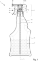
- Fig. 1 shows a proposed dispenser 1 with a proposed dispensing device 2 and a container 3.
- a fluid F can be contained in the dispenser 1 or container 3.
- the dispensing device 2 is designed to convey the fluid F from the container 3 and to discharge or dispense the fluid F.
- the fluid F is preferably a (low-viscosity) liquid, in particular a cleaning liquid or similar, but can also have a viscous to pasty consistency or a high viscosity.
- the fluid F is dispensed with the dispensing device 2 preferably as a spray or aerosol or as foam.
- the dispensing device 2 preferably as a spray or aerosol or as foam.
- other solutions are also possible here.
- the dispenser 1 is preferably marketed as a disposable item and filled with the fluid F and/or sold to an end customer.
- the dispenser 1 is particularly suitable for cleaning liquids such as glass cleaner or the like, but can also be used for any other fluids.
- the dispenser 1 and/or the dispensing device 2 preferably has or forms a housing 2A.
- the housing 2A is preferably designed in several parts.
- the container 3 preferably forms a part or portion of the housing 2A of the dispenser.
- the housing 2A has the container 3.
- the proposed dispensing device 2 has a pump device 4 for conveying the fluid F, in particular from the container 3.
- the pump device 4 has a bellows 5 or the pump device 4 is formed by the bellows 5.
- the pump device 4 and/or the bellows 5 are preferably arranged at least partially within the housing 2A or accommodated in the housing 2A.
- the bellows 5 is flexible.
- the bellows 5 is elastically deformable or the bellows 5 consists of a flexible and/or elastically deformable material.
- the bellows 5 is preferably designed to return after deformation to a starting position or unactuated position or rest position that was assumed before the deformation. This will be discussed in more detail later.
- the bellows 5 is preferably installed or arranged in the dispenser 1 or the dispensing device 2 or the pumping device 4 in a prestressed and/or (slightly) compressed manner. This particularly supports reliable delivery of fluid F.
- the bellows 5 is preferably at least essentially cylindrical or hollow cylindrical.
- a lateral surface or side wall 6 of the bellows 5 is preferably wavy or corrugated. This preferably increases the flexibility and/or elastic restoring force that drives or moves the bellows 5 back into the starting position or rest position. Furthermore, the wavy design preferably avoids damage if the bellows 5 is deformed and/or increases the stability of the bellows 5.
- the bellows 5 or the side wall 6 preferably runs coaxially to a central or longitudinal axis L of the dispenser 1 or the dispensing device 2.
- the axis L is preferably aligned at least substantially perpendicularly (vertically) in a usual storage position and/or use position of the dispenser 1, as also shown in the figures.
- the dispensing device 2 or its dispensing head 14 is usually at the top and the container 3 at the bottom.
- the axis L at least in the storage position, runs parallel to gravity.
- the dispenser 1 In the storage position, the dispenser 1 preferably stands on a bottom of the container 3.
- an “axial” direction or movement is preferably understood to mean a direction or movement that runs along or parallel to the axis L.
- the term “radial” preferably also refers to the axis L.
- top and bottom as well as modifications thereof and similar terms in the present invention preferably have the usual general language meaning with regard to the preferred orientation or position of use and in the present invention preferably refer to the storage position of the dispenser shown in the figures 1 or the delivery facility 2.
- the pump device 4 or the bellows 5 preferably has an inlet 5A for the fluid F, an outlet 5B for the fluid F and a pump chamber or interior 5C for receiving the fluid F.
- the interior 5C is preferably formed between the inlet 5A and the outlet 5B and/or delimited laterally or radially by the side wall 6.
- the pump device 4 or the bellows 5 preferably has an inlet valve 7 at the inlet 5A and an outlet valve 8 at the outlet 5B.
- the inlet valve 7 and the outlet valve 8 are preferably each designed as a one-way valve.
- the inlet valve 7 enables or controls a supply of the fluid F to the bellows 5.
- the outlet valve 8 enables or controls a delivery of the fluid F from the outlet 5B of the bellows 5.
- the inlet valve 7 and the outlet valve 8 open and/or close preferably under pressure control or automatically, in particular by a pressure difference present at the respective valve 7, 8.
- the specific design of the valves 7, 8 will be discussed in more detail later.
- the pump device 4 has a base 9.
- the base 9 is designed as a separate or separately manufactured component from the bellows 5.
- the base 9 is preferably axially movable and/or arranged within the housing 2A.
- the base 9 is connected to the bellows 5 on the inlet side.
- the bellows 5 preferably has a fastening section 5D, via which the bellows 5 is connected to the base 9.
- the fastening section 5D is preferably at least essentially hollow cylindrical, ring-like or conical.
- the fastening section 5D can be non-positively or frictionally and/or cohesively connected to the base 9 or attached to the base 9, in particular locked, glued, welded and/or sprayed on.
- the fastening section 5D preferably runs coaxially to the axis L.
- the base 9 has a floor element 10.
- the base element 10 is preferably designed like a plate and/or preferably forms a (lower) end surface or a (lower or end) closure of the pump device 4 or the bellows 5 or the interior 5C.
- the base element 10 is preferably designed at least substantially like a circular disk and/or forms an annular surface.
- the floor element 10 preferably has a ring section 10A, in particular complementary to the fastening section 5D, which is in particular arranged coaxially to the axis L and/or the fastening section 5D.
- the attachment portion 5D is attached to or connected to the ring portion 10A.
- the base 9 has or forms a supply channel 11 for the fluid F, which runs in particular axially or parallel to the axis L.
- the feed channel 11 preferably opens into the inlet 5A of the bellows 5.
- the feed channel 11 is formed or limited by a line 12 of the base 9.
- the line 12 and the base element 10 are formed in one piece.
- the base 9 with the base element 10 and the supply line 12 can be designed or manufactured, for example, as an injection molded component and/or made of plastic.
- the base element 10 is preferably arranged at a distance from the upper or the bellows 5 facing and/or the lower or the container 3 facing axial end of the line 12.
- the line 12 particularly preferably forms a connection and/or projects downwards or into the container 3.
- the fastening section 5D is preferably arranged or fastened on an upper axial end of the line 12 or the bellows 5 facing.
- the dispenser 1 or the dispensing device 2 or the pump device 4 preferably has a riser 13 for the fluid F.
- the riser 13 is preferably connected to the bellows 5 or the base 9, in particular to the feed channel 11 or the line 12, and / or a lower end or to an end of the base facing away from the floor element 10 and / or the bellows 5 9 or line 12 arranged.
- the riser 13 can be inserted into the line 12 or attached to the line 12 or connected to the line 12 in some other way.
- the riser 13 preferably forms an extension of the line 12 or the feed channel 11.
- the line 12 and the riser 13 together form and/or delimit the feed channel 11.
- the dispenser 1 or the dispensing device 2 preferably has a spray head or dispensing head 14 for discharging or dispensing the fluid F.
- the dispensing head 14 forms a part or section of the housing 2A or the housing 2A has the dispensing head 14.
- the dispensing head 14 is preferably arranged on the outlet side on the bellows 5 or the pump device 4 and/or fluidly connected or connectable to the bellows 5 or the outlet 5B.
- the dispensing head 14 preferably has a fastening part 14A for connecting or fastening the pump device 4 or the bellows 5 to/on the dispensing head 14.
- the fastening part 14A is preferably a separate or separately manufactured component from the dispensing head 14.
- other solutions are also possible here.
- the fastening part 14A preferably has one or more openings 14B for the fluid F, which are preferably designed like slots.
- the dispensing head 14 preferably has or forms an outlet channel 15 which runs in particular transversely or perpendicular to the axis L.
- the outlet channel 15 is preferably fluidly connected or connectable to the outlet 5B, in particular through the opening(s) 14B in the fastening part 14A, and opens into an outlet opening 16.
- the fluid F can preferably flow via the outlet channel 15 and the outlet opening 16 emerge from the dispensing head 14 or are dispensed by the dispenser 1 or the dispensing device 2.
- the fluid F is dispensed from the dispenser 1 or the dispensing device 2 preferably by actuating the pump device 4 or the bellows 5, in particular by means of an actuating lever 21.
- the actuating lever 21 will be discussed in more detail later.
- the fluid F preferably passes from the container 3 via the feed channel 11 or the line 12 and/or the riser line 13 into the delivery device 2 or the pump device 4 or the bellows 5.
- the inlet valve 7 is preferably designed in such a way that it opens when the fluid F is delivered with the pump device 4 or when the fluid pressure is present on the supply channel side and thus enables the fluid F to be delivered from the supply channel 11 through the inlet valve 7 into the interior 5C of the bellows 5 .
- the bellows 5 is preferably in an unactuated position or rest position, which is in Fig. 1 is shown, and in an actuated or compressed position, which is shown in Fig. 3 is shown, can be positioned or arranged or deformed into these positions.
- the bellows 5 is preferably designed to automatically assume or return to the rest position, in particular by elastic resetting, if no force deforming the bellows 5 from the rest position acts on the bellows 5.
- the bellows 5 is compressed axially or along the axis L in the actuated position. The compression of the bellows 5 takes place in particular axially or parallel to the axis L and/or by pushing or folding the corrugated side wall 6 together.
- the bellows 5 is preferably held or fastened in a stationary or immovable manner on the outlet side, in particular by or on the dispensing head 14.
- the outlet 5B and/or the dispensing head 14 change their (axial) position relative to the housing 2A and/or the container 3 does not occur when the bellows 5 is compressed or deformed or when the dispensing device 2 or the dispenser 1 is actuated.
- the bellows 5 is preferably movably held or fastened on the inlet side, in particular by or on the base 9.
- the inlet 5A and/or the base 9 preferably change their (axial) position relative to the housing 2A and/or the container 3 at a time Compression or deformation of the bellows 5 or when the dispensing device 2 or the dispenser 1 is actuated.
- the compression or volume reduction of the bellows 5 causes an increased pressure of the fluid F located in the interior 5C of the bellows 5, so that the fluid F is present at the outlet valve 8 at an increased pressure, through which the outlet valve 8 preferably opens.
- the compression of the bellows 5 therefore preferably causes the fluid F to enter the outlet channel 15 through the outlet valve 8 and to leave it via the outlet opening 16 and thus to be discharged from or by the dispensing device 2.
- the bellows 5 When the operation of the pump device 4 is ended or no compressive force (any longer) acts on the bellows 5, the bellows 5 preferably returns to the rest position, in particular by elastic resetting.
- the expansion of the bellows 5 from the compressed or actuated position into the rest position reduces the pressure in the interior 5C of the bellows or creates a negative pressure in the bellows 5 or its interior 5C during the expansion, through which preferably the outlet valve 8 closes.
- the inlet valve 7 is preferably opened by the negative pressure, so that fluid F present in the supply channel 11 at the inlet valve 7 flows or can flow through the inlet valve 7 into the interior 5C of the bellows 5.
- the inlet valve 7 is preferably formed by the line 12 and the bellows 5.
- the inlet valve 7 or the bellows 5 has a valve element 7A formed in one piece with the bellows 5.
- the valve element 7A preferably closes
- an end opening 11A of the feed channel 11 or the line 12, which opens into the interior 5C, is fluid-tight.
- the opening 11A is sealingly covered by the valve element 7A - at least in the closed position.
- the valve element 7A is preferably held by one or more, in particular flexible, arms 7B of the bellows 5, in particular in the closed position.
- the arms 7B are preferably designed like a web.
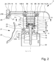
- the arms 7B are particularly in Fig. 4 shown.
- valve element 7A is preferably biased against the opening 11A or the feed channel 11, in particular by means of the arms 7B.
- the arms 7B are preferably arranged between the fixing portion 5D of the bellows 5 and the valve element 7A.
- the valve element 7A is preferably arranged coaxially with and/or centrally in the fastening section 5D.
- the arms 7B preferably lie in a plane running transversely, in particular perpendicularly, to the axis L.
- one end of an arm 7B is arranged on the valve element 7A and/or one end of an arm 7B is arranged on the fastening section 5D.
- the arms 7B can project radially or tangentially from or extend to the valve element 7A.
- the arms 7B are curved or the arms 7B run at least essentially radially at their ends and in a central section or spaced from the ends in a circular arc-like manner and/or coaxially to the axis L, in particular parallel to the outer contour of the valve element 7A and/or to the inner edge of the attachment section 5D.
- the curved arms 7B are extended compared to radially extending or arranged arms 7B, so that opening the inlet valve 7 is easier.
- the outlet valve 8 is preferably formed by a particularly ring-like sealing lip 8A, which - at least in the closed state of the outlet valve 8 - rests sealingly on a counter surface 8B, which is preferably designed like a ring and/or is arranged coaxially to the axis L, and is in particular biased against the counter surface 8B .
- a counter surface 8B which is preferably designed like a ring and/or is arranged coaxially to the axis L, and is in particular biased against the counter surface 8B .
- the sealing lip 8A In an open position of the outlet valve 8, the sealing lip 8A is lifted off the counter surface 8B, so that a gap is formed between the sealing lip 8A and the counter surface 8B, through which the fluid F emerges from the interior 5C of the bellows 5 and into the outlet channel 15 can occur.
- the fastening part 14A has or forms the counter surface 8B.
- the dispenser 1 or the dispensing device 2 is designed in such a way that when the pump device 4 is actuated, the container 3 is automatically ventilated, so that during or through the conveying and/or dispensing of the fluid F from the Container 3 no (too high) negative pressure is created in the dispenser 1 or the container 3.
- a negative pressure could lead to a deformation of the container 3 and/or prevent or make it more difficult (further) delivery of the fluid F from the container 3, which is undesirable.
- the dispenser 1 or the dispensing device 2 is preferably designed so that when the pump device 4 is actuated, in particular when the bellows 5 or the base 9 moves axially, a ventilation gap 17 is formed, through which ventilation of the container 3 is made possible or . he follows.
- the dispensing device 2 preferably has or forms a seat or a guide 18 for the base 9 or the line 12.
- the ventilation gap 17 can be formed between the line 12 and the guide 18.
- the ventilation gap 17 is preferably designed like a ring.
- the guide 18 is preferably designed to be ring-like and/or hollow cylindrical, at least in sections.
- the guide 18 is in particular arranged coaxially to the axis L.
- the line 12 is preferably held by the guide 18 or within the guide 18 and / or arranged or can be arranged in the guide 18.
- the ventilation gap 17 is formed in particular by the line 12 being lifted or spaced apart from the guide 18 during an axial movement.
- the ventilation gap 17 is formed between the guide 18 and the line 12 when the pump device 4 is actuated, in particular when the bellows 5 is compressed or is deformed from the rest position into the compressed position and/or when the base 9 moves axially upwards or is moved in the direction of the dispensing head 14.
- the ventilation gap 17 is preferably formed during the axial movement of the base 9 or line 12 in that the line 12 has or forms a (conically) tapered section or a particularly conical taper 19 on the outside.
- the taper 19 is preferably arranged in the area of the guide 18 on the line 12.
- the outer diameter of the line 12 is preferably changed, in particular reduced downwards or with increasing distance from the bellows 5.
- the distance between the line 12 or taper 19 and the guide 18 is changed, in particular increased, in particular when the base 9 or line 12 moves axially (in the direction of the bellows 5 or upwards), so that the ventilation gap 17 is formed.
- the guide 18 preferably forms and/or has a seat and/or stop 18A for the line 12.
- the stop 18A is preferably designed to prevent and/or block an axial movement of the base 9 or line 12 downwards or in the direction of the container 3.
- the stop 18A is preferably designed as a projection projecting radially inwards from the guide 18 or its inside, in particular as an annular bead.
- the dispensing device 2 has a connecting part 20.
- the connecting part 20 preferably forms a part or section of the housing 2A or the housing 2A has the connecting part 20.
- the connecting part 20 preferably has the guide 18 or forms it.
- the dispensing device 2 is attached to the container 3 with or through the connecting part 20.
- the connecting part 20 can, for example, be screwed onto the container 3 and/or connected to the container 3 in a latching manner.
- other solutions are also possible here.
- the connecting part 20 is preferably arranged axially between the container 3 and the bellows 5 and/or the dispensing head 14.
- the dispenser 1 or the dispensing device 2 or the housing 2A preferably has a housing part 2B.
- the housing part 2B forms a part or section of the housing 2A.
- the housing part 2B is preferably at least essentially sleeve- or ring-like or hollow cylindrical and/or arranged coaxially to the axis L.
- the housing part 2B is preferably arranged (axially) between the connecting part 20 and the dispensing head 14 or connects them to one another.
- the bellows 5 is preferably arranged within the housing part 2B and/or coaxially therewith.
- the dispensing head 14, the fastening part 14A, the housing part 2B and/or the connecting part 20 can each be connected to one another in a force-fitting, form-fitting and/or fluid manner, in particular locked, screwed, glued, welded or molded on. It is also possible for one or more of the parts 14, 14A, 2B, 20 mentioned to be formed in one piece or to form different sections of a single component.
- the dispensing device 2 or pumping device 4 has an operating lever 21 for manual actuation of the dispensing device 2 or the pumping device 4.
- the pumping device 4 is actuated or the bellows 5 is compressed to deliver the fluid F (exclusively) by (manually) actuating the actuating lever 21 by a user (not shown).
- the pump device 4 or delivery device 2 also can be realized without the actuating lever 21 or can be actuated in a different way than with the actuating lever 21 described in more detail below. Solutions are conceivable here, for example, in which the pumping device 4 is actuated or the bellows 5 is compressed by an axial movement or a dispensing head is pressed down, for example in FIG WO 2015/106868 A1 or the US 2012/0024904 A1 described.
- the properties and features of the actuating lever 21 described below, in particular with regard to securing against actuation, are carried out independently of the implementation of the pump device 4 by or with a flexible bellows .
- a cylinder-piston arrangement is also conceivable, for example similar to that in the US 3,840,157 cylinder-piston arrangement described.
- the actuating lever 21 is pivotably arranged or mounted on the dispensing device 2, in particular the housing 2A.
- the actuating lever 21 has an actuating arm 22 and a lifting arm 23 coupled to the actuating arm 22 or is formed by them.
- the actuating arm 22 is preferably arranged outside the housing 2A or housing part 2B.
- the lifting arm 23 is preferably arranged at least in sections or predominantly within the housing 2A or housing part 2B or protrudes into it.
- the housing 2A or housing part 2B preferably has a recess or opening through which the actuating lever 21 or lifting arm 23 can be carried out or carried out.
- the actuating lever 21 is in particular Fig. 5 shown.
- the actuation arm 22 is designed for manual actuation by a user, not shown.
- the actuating arm 22 can be curved or curved and/or ergonomically shaped. This is conducive to easy and comfortable operation.
- the lifting arm 23 is designed to drive the pump device 4, in particular to actuate or compress the bellows 5 and/or to axially move the base 9, in particular upwards or in the direction of the outlet 5B and/or dispensing head 14.
- the lifting arm 23 is preferably arranged at an end section of the actuating arm 22, in particular so that the greatest possible leverage can be generated during actuation via the actuating arm 22.
- actuating lever 21 is in a first or unactuated pivot position and in Fig. 3 shown in a second or actuated pivot position.
- the actuating lever 21 can be pivoted between the first or unactuated and the second or actuated pivot position.
- the movement from the first to the second pivoting position is preferably carried out by manual actuation or pivoting of the actuating lever 21 by a user, not shown.
- the base element 10 of the base 9 forms or has a counter surface or actuating surface for the actuating lever 21 or lifting arm 23.
- the actuating lever 21 or lifting arm 23 preferably rests on the base element 10 or the actuating surface formed thereby and/or acts on it and/or exerts a force thereon, in particular when pivoting from the first to the second pivoting position.
- the bellows 5 is preferably actuated or compressed and / or deformed or moved from the rest position to the compressed position. This is done in particular by the fact that during the actuation or pivoting movement of the lifting arm 23 rotates about a pivot axis or a bearing part 24, so that an end of the lifting arm 23 assigned or facing the base 9 is raised or moved in the direction of the bellows 5.
- an actuation of the actuation lever 21 or a pivoting of the actuation lever 21 from the first to the second pivot position causes compression of the bellows 5 and/or discharge of the fluid F.
- a movement of the actuating lever 21 from the second or actuated pivot position (back) into the first or unactuated pivot position occurs automatically or no active movement or actuation of the actuating lever 21 is required for this.
- a movement from the second to the first pivot position can preferably be carried out by a user releasing the actuating arm 22.
- the expansion of the bellows 5 and/or the movement of the actuating lever 21 from the second to the first pivot position, in particular caused by the expansion, is preferably carried out by the (elastic) restoring force, which is caused by the previous elastic deformation or compression of the bellows 5 becomes.
- the base 9 or the base element 10 or the actuating surface formed thereby preferably acts on the actuating lever 21 or lifting arm 23 or exerts a force on the actuating lever 21 or lifting arm 23, so that the actuating lever 21 is moved or pivoted from the second pivot position into the first pivot position.
- the lifting arm 23 is formed by two mutually parallel, in particular arm-like or web-like elements 23A, which are connected to or arranged on the actuating arm 22 on one side and on the end side opposite the actuating arm 22 by a further element 23B, which is transverse or . Arranged at right angles to the elements 23A, are rigidly connected to one another. In this way, a lifting arm 23 that is both stable and saves material is formed.
- arm-like or web-like elements 23A Arranged at right angles to the elements 23A, are rigidly connected to one another. In this way, a lifting arm 23 that is both stable and saves material is formed.
- other solutions are also possible here.
- a particularly rounded or cylindrical bearing part 24 is arranged or fastened between the elements 23A.
- the bearing part 24 preferably runs transversely, in particular vertically, between the elements 23A.
- the bearing part 24 is preferably formed in one piece with the lifting arm 23 and/or the actuating arm 22.
- the actuating lever 21, the actuating arm 22 and/or the lifting arm 23 can be formed by a (one-piece) injection molded component.
- other solutions are also possible.
- the actuating lever 21 is pivotally mounted on the dispensing device 2, in particular the housing 2A or the connecting part 20, by means of the bearing part 24.
- the bearing part 24 preferably forms a rotation axis or pivot axis about which the actuating lever 21 can be pivoted or is pivoted when actuated.
- the connecting part 20 has a bearing 25 for the bearing part 24 which is complementary to the bearing part 24.
- the bearing 25 is designed in particular for the preferably rotatable holding or mounting of the bearing part 24 or actuating lever 21.
- the bearing part 24 can be arranged or fastened, preferably in a latching manner, in the bearing 25, in particular with the bearing 25 holding the bearing part 24 in a form-fitting manner and/or at least partially surrounding it.
- actuating lever 21 is shown in a position of use.
- the position of use is preferably that position or relative arrangement of the actuating arm 22 and lifting arm 23 to one another in which an actuation of the actuating lever 22 for dispensing the fluid F takes place or can take place.
- position of use refers to a relative arrangement of the actuating arm 22 and the lifting arm 23 to one another, but not a pivoting position of the actuating lever 21.
- the lifting arm 23 and the actuating arm 22 are preferably arranged transversely, in particular at least substantially perpendicularly, to one another - at least in the position of use.
- the actuating arm 22 can be folded down, in particular from the lifting arm 23, and/or the actuating arm 22 is movable relative to the lifting arm 23, in particular foldable or pivotable. This functionality is particularly important in the Fig. 6 to 8 illustrated embodiments realized.
- the actuating arm 22 can preferably be secured by folding down or folding up or up, and/or on the dispensing head 14 against actuation and/or in a securing position.
- the actuating lever 21 or actuating arm 22 can preferably be arranged in a securing position or folded into a securing position, so that the operating lever 21 is secured or can be secured against actuation in the securing position.
- actuating lever 21 is shown in the securing position or with the actuating arm 22 folded down.
- actuating lever 21 or operating arm 22 Various implementations are possible for securing the operating lever 21 or operating arm 22.
- Fig. 6 to 8 show two preferred embodiments, which can also be combined with one another.
- Fig. 6 shows a (second) exemplary embodiment in which the actuating arm 22 can be secured to the dispensing head 14 in a form-fitting manner.
- the dispensing head 14 preferably has a closure 26 for this purpose.
- the closure 26 is preferably implemented or designed separately or as a component separate from the dispensing head 14.
- the closure 26 preferably forms a securing part or securing element for the actuating arm 22 or actuating lever 21.
- the closure 26 can be connected to the dispensing head 14 and/or can be separated or removed from the dispensing head 14.
- the closure 26 is held or arranged or can be arranged on the dispensing head 14 in a form-fitting and/or latching manner.
- the closure 26 is preferably designed to close or cover the outlet channel 15 or the outlet opening 16 (fluid-tight) and/or to secure or hold the actuating lever 21 or actuating arm 22 in the securing position, in particular in a form-fitting manner.
- the outlet channel 15 or the outlet opening 16 is simultaneously closed and the actuating arm 22 is held in a form-fitting manner in the securing position or secured against actuation.
- the closure 26 preferably forms, at least in the figure Fig. 6 position shown, a stop for the actuating arm 22, against which the actuating arm 22 rests in the securing position and through which a movement of the actuating arm 22, in particular into the use position, is blocked.
- the closure 26 is movably arranged on or connected to the dispensing head 14 in such a way that the outlet channel 15 or the outlet opening 16 and/or the actuating arm 22 can be released or unlocked.
- a release or unlocking of the actuating arm 22 is preferably carried out by rotating the closure 26 into an unlocking position, in particular by at least substantially approximately 90 ° starting from the in Fig. 6 shown closure position of the closure 26.
- the unlocking position of the shutter 26 is in Fig. 7 shown.
- the closure 26 is preferably elongated, so that by rotating it from the locking position into the unlocking position or by approximately 90° from the locking position, the positive locking or blocking of the actuating arm 22 is released or the lock is pivoted away from the actuating arm 22.
- the outlet channel 15 or the outlet opening 16 is preferably released for fluid delivery.
- the outlet opening 16 or the outlet channel 15 preferably opens into a delivery opening 28 of the closure 26 or the delivery opening 28 is fluidly connected to the outlet channel 15.
- the delivery opening 28 preferably forms an extension or part of the outlet channel 15.
- the delivery opening 28 and/or outlet opening 16 can be designed as a nozzle or nozzle-like and/or designed in such a way that a desired delivery form of the fluid F is achieved or effected through the delivery opening 28 and/or outlet opening 16 or its shape, for example as Spray or aerosol or foam.
- the closure 26 can preferably be arranged on a connecting element 27 of the dispensing head 14 or can be connected to the connecting element 27, in particular by plugging or sliding onto the connecting element 27.
- the closure 26 is positively locking or latching on the connecting element 27, in particular movable or rotatable , held.
- the connecting element 27 is preferably designed as a part protruding from the closure 26 or an end face 26A of the closure 26.
- the connecting element 27 preferably has an elongated, in particular cylindrical, section 27A arranged on the end face 26A.
- the connecting element 27A or the section 27A preferably has a head 27B, which is widened in particular compared to the section 27A or projects radially beyond the section 27A, so that the closure is positively or latching on the connecting element 27 or .
- the head 27B can be arranged or connected to it.
- the closure 26 is preferably rotatable about the connecting element 27, in particular in such a way that the connecting element 27 has or forms an axis of rotation D for the closure 26.
- the axis of rotation D preferably runs transversely, in particular perpendicular, to the axis L.
- the actuating arm 22 can be secured in a latching manner by or with the closure 26.
- the actuating arm 22 and the closure 26 can have mutually assigned or mutually complementary elements for producing a locking connection, for example locking cams or the like.
- the locking connection between the actuating arm 22 and the closure 26 - in contrast to that in Fig. 6 illustrated embodiment - on the side facing away from the dispensing head 14, i.e. in the left side of the closure 26 in Fig. 6 , is provided or is manufactured.
- the actuating lever 21 or actuating arm 22 can be secured or arranged in a securing position on the dispensing head 14 without the additional closure 26 or which is manufactured separately from the dispensing head.
- the dispensing head 14 preferably has or forms a stop or a shoulder 14C, particularly in the area of the outlet opening 16 or at the end.
- the shoulder 14C can in particular be similar or at least essentially like that in Fig. 6 indicated shoulder 14C may be formed.
- the free end of the actuating arm 22 is preferably analogous to that in Fig. 6 illustrated embodiment with the closure 26 - can be secured by the shoulder 14C or secured or clamped in a form-fitting manner behind the shoulder 14C.
- the length of the actuating arm 22 is preferably selected or adjusted accordingly, so that the free end can be secured in a form-fitting manner by the shoulder 14C.
- the actuating arm 22 and/or the shoulder 14C are designed to be flexible or deformable in such a way that the actuating arm 22 can be moved past the shoulder 14C with slight, increased effort starting from the securing position, preferably the shoulder 14C and/or the actuating arm 22 be easily deformed and thus enable movement or unlocking.
- Fig. 8 shows a third embodiment or a further variant for securing the actuating arm 22 on the dispensing head 14 and / or closing the outlet channel 15 or the outlet opening 16 by the actuating lever 21 or actuating arm 22.
- the dispensing head 14 preferably does not have an additional closure 26 or can be dispensed with.
- the actuating lever 21 or actuating arm 22 or one end 22A thereof is designed directly to close or seal the outlet channel 15 or the outlet opening 16.
- the end 22A of the actuating arm 22 can be arranged or fastened on the dispensing head 14, in particular can be placed or pushed over the outlet opening 16.
- the end 22A of the actuating lever 21 or actuating arm 22 assigned to the outlet opening 16 is preferably designed like a sleeve or has a sleeve for covering or closing the outlet opening 16 or the outlet channel 15.
- Elements, not shown, can be arranged to produce a locking connection between the actuating arm 22 and the dispensing head 14 or the actuating arm 22 and the dispensing head 14 can have corresponding elements assigned to one another or complementary, for example locking cams or the like.
- the actuating arm 22 and the lifting arm 23 are preferably movable relative to one another, in particular pivotable. As already explained previously, the actuating arm 22 can be folded down in particular from the lifting arm 23.
- the actuating arm 22 or actuating lever 21 is preferably in a position of use which is in the Fig. 1 to 5 is shown, and in a securing position, which is in the Fig. 6 to 8 is shown, positionable.
- the actuating arm 22 is preferably connected to the lifting arm 23 by a solid joint or film hinge 29.
- the film hinge 29 preferably consists of the same material as the lifting arm 23 and/or the actuating arm 22, in particular made of plastic.
- the film hinge 29 is preferably flexible and/or deformable, in particular due to a correspondingly small thickness or material thickness.
- the actuating lever 21 can preferably be secured or arranged in a form-fitting and/or latching manner in the position of use.
- the actuating arm 22 and the lifting arm 23 have a latching connection or corresponding and/or mutually corresponding latching elements 30, which are in the position of use engage in a form-fitting or latching manner and/or hold or secure or fix the actuating arm 22 in the position of use on the lifting arm 23.
- the latching connection or the latching elements 30 are designed such that when the actuating arm 22 moves from the securing position to the use position at the end of the movement, the latching connection is automatically established or the latching elements 30 are automatically connected to one another or snap into one another.
- the latching connection or the latching elements 30 can be designed in such a way that after a first or one-time movement of the actuating arm 22 (from the securing position) into the use position or after a one-time or first-time connection, they can no longer be locked or only with great effort and / or can be separated from each other with damage to the operating lever 21.
- the locking connection can be released or separated again, so that the actuating lever 21 can be secured again and / or the actuating arm 22 can be repeatedly moved from the securing position to the use position and secured in the respective position or vice versa.
- the movement or folding of the actuating arm 22 from the use position to the securing position can be limited and/or a further movement can be blocked after a certain movement path or folding or pivoting angle, in particular if the actuating arm 22 has reached the safety position.
- movement of the actuating arm 22 beyond the securing position is blocked, in particular in a form-fitting manner.
- a movement of the actuating arm 22 beyond the securing position can be blocked in that an end section or region of the actuating arm 22 - in particular the upper section of the actuating arm 22 in the figures - is in the securing position or another end position on the lifting arm 23 or its The top comes to rest and thus further movement or pivoting is blocked.
- the actuating arm 22 and/or the lifting arm 23 can also have correspondingly designed projections, shoulders, stops or other suitable sections, areas or parts.
- the actuating arm 22 or actuating lever 21 can be secured against unwanted actuation or in the securing position by the actuating arm 22 (in the securing position) engaging on the lifting arm 23.
- the actuating arm 22 and/or the lifting arm 23 preferably have corresponding locking elements for this purpose.
- the locking connection formed in this way is preferably releasable.
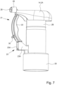
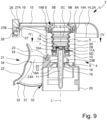
- a fourth embodiment of the present invention is described below in particular with reference to Fig. 9 and 10 explained.
- differences from the first, second and third embodiments are primarily explained. Unless any deviations or differences between the embodiments are explained, the above statements preferably also apply to the fourth embodiment described below.
- the dispensing device 2 according to the fourth embodiment has a locking element 31, in particular in addition to the other parts and components already described above.
- the locking element 31 is preferably designed to be movable.
- the locking element 31 is arranged to be movable or movable relative to the actuating lever 21 or actuating arm 22 and/or relative to the housing 2A.
- the actuating lever 21 is not rotatable relative to the housing 2A or about the axis L.
- the actuating lever 21 or actuating arm 22 preferably has the locking element 31.
- the locking element 31 is preferably arranged or attached to the actuating lever 21, in particular actuating arm 22, in particular on a side facing the housing 2A. In principle, however, it is also possible to arrange or fasten the locking element 31 on the housing 2A. The following statements then apply in reverse.
- the locking element 31 is arranged on the actuating lever 21 or actuating arm 22 in a pivotable or pivotable manner relative to the actuating lever 21 or actuating arm 22, in particular by means of a flexible and/or articulated connecting piece 32.
- the connecting piece 32 can be formed, for example, by a film hinge or the like be.
- the locking element 31 is preferably elongated and/or rod-like.
- Fig. 9 the operating lever 21 is shown in a secured or locked position or locking position.
- locked position and “locked position” are used interchangeably.
- the locking element 31 is preferably arranged between the actuating lever 21 or actuating arm 22 and the housing 2A, in particular housing part 2B, in particular transversely to the housing 2A, in particular housing part 2B, and / or the actuating arm 22.
- the locking element is preferably located 31 in the locked position on the housing 2A and/or the locking element 31 is clamped in the locked position between the actuating arm 22 and the housing 2A or housing part 2B.
- the locking element 31 is preferably designed to be flexible and/or elastic.
- the locking element 31 is elastically deformed in the locked position and/or the locking element 31 is under tension in the locked position, in particular compressive tension, so that the actuating lever 21 or actuating arm 22 is reliably blocked against actuation and/or pushed into the locked position or . is biased.
- the locking element 31 can preferably be clamped on several sides, in particular between the actuating lever 21 or actuating arm 22 and the housing 2A or housing part 2B.
- the locking element 31 is preferably curved. This enables or facilitates tension or pre-tension in a defined direction.
- the locking element 31 is arranged or fixed in the locked position between the housing 2A or housing part 2B and the actuation arm 22, so that the actuation arm 22 cannot be moved out of the locked position or is blocked against actuation.
- the housing 2A or housing part 2B can have a fixing device 33.
- the fixing device 33 preferably has or consists of one or more locking elements, so that the locking element 31, in particular a free end of the locking element 31 or an end on a side of the locking element 31 facing away from the connecting piece 32, in which the fixing device 33 can be snapped and thus fixed.
- the fixing device 33 is designed in particular for releasably fixing or fastening the locking element 31.
- the locking element 31 is not damaged when released from the fixing device 33.
- the locking element 31 can preferably be used multiple times or can be arranged or fixed again in the fixing device 33 after being released from the fixing device 33.
- the actuating lever 21 or actuating arm 22 is preferably pivoted away from the housing 2A or housing part 2B or held or fixed by the locking element 31 in a position pivoted away from the housing 2A or housing part 2B.
- the actuating lever 21 or lifting arm 23 preferably rests on the connecting part 20 or an upper section of the guide 18. In this way, the actuating lever 21 is secured in two directions against movement out of the locking position.
- the locking element 31 can be pivoted or folded out of the locked position and/or into a second position or can be moved into the second position in some other way.
- the second position of the locking element 31 is in Fig. 10 shown.
- the locking element 31 can preferably be released from the fixing device 33 and/or moved into the second position by applying a force transversely to the main extension direction of the locking element 31.
- the locking element 31 is preferably arranged such that the actuating lever 21 or the dispensing device 2 can be freely actuated, in particular without restriction or hindrance to actuation by the locking element 31.
- the actuating lever 21 or the actuating arm 22 is preferred Approved.
- the locking element 31 In the second position, the locking element 31 preferably rests on the actuating arm 22 and/or is embedded in the actuating arm 22.
- the locking element 31 can be folded onto the actuating arm 22 or in the second position folded onto the actuating arm 22 and/or folded into the actuating arm 22 or folded into the actuating arm 22 in the second position.
- the locking element 31 does not protrude from the actuating arm 22 in the second position.
- the locking element 31 can be folded away from the actuating arm 22 or folded out of the actuating arm 22. In particular, this makes it possible to secure or lock the actuating lever 21 or actuating arm 22 again.
- the actuating lever 21 or actuating arm 22 preferably has a fixing device 34 for fixing the locking element 31 in the second position.
- the fixing device 34 of the actuating lever 21 is preferably designed similarly or identically to the fixing device 33 of the housing 2A. The above statements regarding the fixing device 33 of the housing 2A therefore preferably apply correspondingly to the fixing device 34 of the actuating lever 21.
Landscapes
- Containers And Packaging Bodies Having A Special Means To Remove Contents (AREA)
- Reciprocating Pumps (AREA)
- Closures For Containers (AREA)
Claims (12)
- Dispositif de distribution (2) pour distribuer un fluide (F),le dispositif de distribution (2) présentant une partie de connexion (20) pour fixer le dispositif de distribution (2) à un récipient (3), un dispositif de pompage (4) avec un soufflet (5) flexible pour transporter le fluide (F) et un levier d'actionnement (21) pour actionner le dispositif de pompage (4),le dispositif de pompage (4) présentant une base (9) reliée au soufflet (5) du côté de l'admission, avec un canal d'alimentation (11) pour le fluide (F),la base (9) étant réalisée sous forme de composant fabriqué séparément du soufflet (5) et présentant un élément de fond (10) et une conduite (12) formant et/ou délimitant le canal d'alimentation (11),la conduite (12) et l'élément de fond (10) étant formés d'une seule pièce et l'élément de fond (10) présentant ou formant une contre-surface pour le levier d'actionnement (21),le levier d'actionnement (21) présentant un bras d'actionnement (22) pouvant être actionné manuellement et un bras de levage (23) couplé à celui-ci pour entraîner le dispositif de pompage (4),le bras de levage (23) étant formé par deux éléments (23A) s'étendant parallèlement l'un à l'autre,le levier d'actionnement (21) étant monté pivotant sur le dispositif de distribution (2) au moyen d'une partie de palier (24) disposée entre les deux éléments (23A) du bras de levage (23) s'étendant parallèlement l'un à l'autre, etla partie de connexion (20) présentant un palier (25) complémentaire de la partie de palier (24) du levier d'actionnement (21) pour le maintien en rotation du levier d'actionnement (21).
- Dispositif de distribution (2) selon la revendication 1, caractérisé en ce que la conduite (12) est maintenue de manière étanche dans un guidage (18) et présente à l'extérieur un rétrécissement (19), de sorte que la conduite (12) est soulevée du guidage (18) lors d'un actionnement du dispositif de distribution (2) et/ou d'un mouvement axial et qu'une fente d'aération (17) est ainsi formée entre le guidage (18) et la conduite (12) pour l'aération d'un récipient (3).
- Dispositif de distribution (2) selon la revendication 1 ou 2, caractérisé en ce que le dispositif de distribution (2) comprend une soupape d'admission (7) avec un élément de soupape (7A) pour couvrir de manière étanche une ouverture d'extrémité (11A) du canal d'alimentation (11), l'élément de soupape (7A) étant formé d'une seule pièce avec le soufflet (5) et étant maintenu par un ou plusieurs bras flexibles (7B) du soufflet (5), en particulier les bras (7B) étant incurvés et s'étendant à leurs extrémités au moins sensiblement radialement et, dans une section espacée des extrémités, en arc de cercle et/ou parallèlement au contour extérieur de l'élément de soupape (7A).
- Dispositif de distribution (2) selon l'une des revendications précédentes, caractérisé en ce que l'élément de fond (10) est réalisé en forme de plaque et/ou de disque circulaire et/ou forme une surface annulaire.
- Dispositif de distribution (2) selon l'une des revendications précédentes, caractérisé en ce que le soufflet (5) présente une section de fixation (5D) qui est reliée à la base (9) par adhérence et/ou par friction et/ou est encliquetée, collée et/ou soudée sur la base (9).
- Dispositif de distribution (2) selon l'une quelconque des revendications précédentes, caractérisé en ce que le soufflet (5) comprend une section de fixation (5D) et l'élément de fond (10) comprend une section annulaire (10A) complémentaire de la section de fixation (5D), la section de fixation (5D) étant fixée ou reliée à la section annulaire (10A).
- Dispositif de distribution (2) selon l'une des revendications précédentes, caractérisé en ce que le levier d'actionnement (21) est conçu pour déplacer axialement la base (9) et/ou pour comprimer le soufflet (5), le levier d'actionnement (21) étant en contact avec l'élément de fond (10) et/ou la contre-surface formée par celui-ci et agissant et/ou exerçant une force sur celui-ci.
- Dispositif de distribution (2) selon l'une des revendications précédentes, caractérisé en ce que le levier d'actionnement (21) et/ou le bras d'actionnement (22) peut être bloqué contre un actionnement par un élément de blocage (31) mobile, l'élément de blocage (31) étant disposé entre le levier d'actionnement (21) et/ou le bras d'actionnement (22) et un boîtier (2A) du dispositif de distribution (2) et étant conçu pour bloquer le levier d'actionnement (21) et/ou le bras d'actionnement (22) contre un actionnement non souhaité.
- Dispositif de distribution (2) selon la revendication 8, caractérisé en ce que l'élément de blocage (31) peut pivoter par rapport au levier d'actionnement (21) et/ou au bras d'actionnement (22).
- Dispositif de distribution (2) selon la revendication 8 ou 9, caractérisé en ce que l'élément de blocage (31) est disposé sur le levier d'actionnement (21) et/ou le bras d'actionnement (22) au moyen d'une pièce de liaison (32) flexible et/ou articulée, qui est formée par une charnière à film.
- Dispositif de distribution selon l'une des revendications 8 à 10, caractérisé en ce que, dans une position de blocage, le bras d'actionnement (22) est maintenu et/ou bloqué dans une position pivotée à l'écart du boîtier (2A) au moyen de l'élément de blocage (31).
- Distributeur (1) pour la distribution d'un fluide (F) avec un dispositif de distribution (2) et un récipient (3), le fluide (F) pouvant être transporté hors du récipient (3) avec le dispositif de distribution (2) et pouvant être distribué au moyen du dispositif de distribution (2),
caractérisé
en ce que le dispositif de distribution (2) est réalisé selon l'une des revendications précédentes.
Applications Claiming Priority (2)
| Application Number | Priority Date | Filing Date | Title |
|---|---|---|---|
| DE102018002101.8A DE102018002101B4 (de) | 2018-03-15 | 2018-03-15 | Abgabespeicher und Spender |
| PCT/EP2019/056488 WO2019175349A1 (fr) | 2018-03-15 | 2019-03-14 | Dispositif de distribution et distributeur |
Publications (2)
| Publication Number | Publication Date |
|---|---|
| EP3765205A1 EP3765205A1 (fr) | 2021-01-20 |
| EP3765205B1 true EP3765205B1 (fr) | 2023-10-18 |
Family
ID=65818010
Family Applications (1)
| Application Number | Title | Priority Date | Filing Date |
|---|---|---|---|
| EP19711886.2A Active EP3765205B1 (fr) | 2018-03-15 | 2019-03-14 | Tête de distribution et distributeur |
Country Status (8)
| Country | Link |
|---|---|
| US (1) | US11548022B2 (fr) |
| EP (1) | EP3765205B1 (fr) |
| JP (1) | JP2021518315A (fr) |
| CN (1) | CN111867737A (fr) |
| CA (1) | CA3092178A1 (fr) |
| DE (1) | DE102018002101B4 (fr) |
| ES (1) | ES2968408T3 (fr) |
| WO (1) | WO2019175349A1 (fr) |
Families Citing this family (8)
| Publication number | Priority date | Publication date | Assignee | Title |
|---|---|---|---|---|
| US10676259B1 (en) | 2018-11-15 | 2020-06-09 | Silgan Dispensing Systems Corporation | Two-part dispensing closure system with internal seal and methods of using the same |
| EP4008442B1 (fr) | 2020-12-04 | 2024-07-17 | Aptar Dortmund GmbH | Agencement de distribution et distributeur |
| DE102020007396A1 (de) | 2020-12-04 | 2022-06-09 | Aptar Dortmund Gmbh | Abgabeeinrichtung und Spender |
| DE102021000632A1 (de) * | 2021-02-08 | 2022-08-11 | Büning & Partner Kommanditgesellschaft | Flüssigkeitsspender, Zapfanlage mit Flüssigkeitsspender und Flüssigkeitsbehälter und Verfahren zum Bereitstellen der Zapfanlage |
| US11701676B2 (en) * | 2021-06-21 | 2023-07-18 | Market Ready, Inc. | Trigger sprayer assembly with dual action piston |
| CN118660765A (zh) * | 2021-11-19 | 2024-09-17 | 里克包装系统有限公司 | 用于泡沫产品的单一聚合物往复分配器 |
| EP4469210A1 (fr) | 2022-01-24 | 2024-12-04 | Aptar Dortmund GmbH | Ressort de soupape, pompe, unité de distribution et distributeur |
| JP7696304B2 (ja) * | 2022-01-31 | 2025-06-20 | 株式会社吉野工業所 | トリガー式液体噴出器 |
Citations (1)
| Publication number | Priority date | Publication date | Assignee | Title |
|---|---|---|---|---|
| JP2007244937A (ja) * | 2006-03-13 | 2007-09-27 | Canyon Corp | スポイド式ポンプディスペンサ |
Family Cites Families (45)
| Publication number | Priority date | Publication date | Assignee | Title |
|---|---|---|---|---|
| US3840157A (en) | 1972-10-16 | 1974-10-08 | J Hellenkamp | Hand operated sprayer |
| JPS5823414Y2 (ja) * | 1976-10-19 | 1983-05-19 | 株式会社吉野工業所 | トリガ−式噴霧器 |
| DK426978A (da) | 1977-09-27 | 1979-03-28 | Unilever Nv | Haandbetjent pumpeforstoever |
| US4278187A (en) * | 1979-12-13 | 1981-07-14 | Security Plastics, Inc. | Trigger lock system for pump |
| FR2528328B1 (fr) | 1982-06-11 | 1985-11-22 | Valve Precision Sarl | Dispositif de pulverisation pour liquides |
| US4558821A (en) * | 1983-03-03 | 1985-12-17 | Canyon Corporation | Trigger-type sprayer with integrally formed housing, trigger, nozzle and cylinder |
| DE8713891U1 (de) * | 1987-10-16 | 1989-02-16 | Wella Ag, 6100 Darmstadt | Handpumpe für eine dosierte Entnahme eines fließfähigen Stoffes aus einem Vorratsbehälter |
| US5114052A (en) | 1988-08-25 | 1992-05-19 | Goody Products, Inc. | Manually actuated trigger sprayer |
| DE3837704C2 (de) * | 1988-11-07 | 1994-03-24 | Andris Raimund Gmbh & Co Kg | Pastenspender |
| US4946074A (en) * | 1989-06-15 | 1990-08-07 | Calmar, Inc. | Tamper evident manually actuated pump sprayer |
| JPH03229660A (ja) * | 1990-02-02 | 1991-10-11 | Goody Prod Inc | 噴霧キヤップ |
| DE4041136C2 (de) * | 1990-12-21 | 1994-06-30 | Andris Raimund Gmbh & Co Kg | Dosier- und Spraypumpe zur Abgabe flüssiger, niederviskoser und pastöser Stoffe |
| US5303867A (en) * | 1993-06-24 | 1994-04-19 | The Procter & Gamble Company | Trigger operated fluid dispensing device |
| DE4411031A1 (de) * | 1993-07-22 | 1995-01-26 | Meckenstock Fritz Gmbh | Handhebelbetätigte Pumpe |
| US5561901A (en) * | 1994-10-06 | 1996-10-08 | The Procter & Gamble Company | Assembly process including severing part of integral collapsible pump chamber |
| US5476195A (en) * | 1994-10-06 | 1995-12-19 | Procter & Gamble Company | Pump device with collapsible pump chamber and including dunnage means |
| US5560545A (en) * | 1994-10-31 | 1996-10-01 | Calmar Inc. | Dual in-line trigger sprayer |
| JPH09291879A (ja) * | 1996-04-26 | 1997-11-11 | Canyon Corp | ポンプディスペンサー |
| US5722569A (en) | 1996-07-19 | 1998-03-03 | Contico International, Inc. | Trigger sprayer with discharge port blocking mechanism |
| ID18608A (id) * | 1996-10-22 | 1998-04-23 | Yoshino Kogyosho Co Ltd | Dispenser cairan jenis-picu |
| ES2117470T3 (es) * | 1996-10-24 | 1998-08-01 | Calmar Albert Gmbh | Enganche de seguridad infantil para pulverizador de gatillo. |
| JPH10174914A (ja) * | 1996-12-18 | 1998-06-30 | Yoshino Kogyosho Co Ltd | トリガー式液体噴出器 |
| DE19803693A1 (de) | 1998-01-30 | 1999-08-05 | Trw Automotive Electron & Comp | Stockschalter, insbesondere Lenkstockschalter für Kraftfahrzeuge |
| DE19803696A1 (de) * | 1998-01-30 | 1999-08-05 | Alfred Von Schuckmann | Auf Flaschen o. dgl. zu befestigende Sprühpumpe |
| JP3730018B2 (ja) * | 1998-06-26 | 2005-12-21 | 株式会社吉野工業所 | トリガー式液体噴出ポンプ |
| JP2000042458A (ja) * | 1998-07-30 | 2000-02-15 | Yoshino Kogyosho Co Ltd | トリガー式液体噴出ポンプ |
| JP3805549B2 (ja) * | 1999-02-15 | 2006-08-02 | 株式会社吉野工業所 | トリガー式液体噴出容器 |
| SE9902672D0 (sv) * | 1999-07-12 | 1999-07-12 | Astra Ab | Delivery device |
| US6279784B1 (en) * | 1999-09-27 | 2001-08-28 | O'neill Richard K. | Trigger activated pump sprayer having a combination dual action spring and fluid chamber |
| US6286723B1 (en) * | 2000-03-06 | 2001-09-11 | Saint-Gobain Calmar Inc. | Self-resetting child-resistant trigger sprayer |
| US6669058B1 (en) * | 2002-10-29 | 2003-12-30 | Saint-Gobain Calmar Inc. | Trigger sprayer with nozzle trigger lock |
| US20060113329A1 (en) * | 2004-11-29 | 2006-06-01 | Seaquisperfect Dispensing Foreign, Inc. | Dispenser with lock |
| DE102006005954A1 (de) | 2006-02-02 | 2007-08-16 | Ing. Erich Pfeiffer Gmbh | Dosiereinrichtung mit Arretierung |
| JP5025279B2 (ja) * | 2007-02-14 | 2012-09-12 | 花王株式会社 | トリガー式液体噴出器 |
| WO2009141511A1 (fr) * | 2008-05-20 | 2009-11-26 | Francis Poizot | Amelioration d'une pompe pour distributeur a reservoir sans air |
| FR2943324B1 (fr) | 2009-03-18 | 2011-05-27 | Promens Sa | Dispositif de distribution d'un produit liquide a pateux par pompe de dosage a faible volume mort |
| DE102009044280A1 (de) * | 2009-10-16 | 2011-05-05 | Lindal Dispenser Gmbh | Produktspender |
| CN102464133A (zh) | 2010-11-03 | 2012-05-23 | 余姚晟祺塑业有限公司 | 全塑乳液泵 |
| JP6021222B2 (ja) * | 2012-12-28 | 2016-11-09 | 株式会社吉野工業所 | トリガー式液体噴出器 |
| DE102014009155A1 (de) | 2013-10-18 | 2015-04-23 | Aptar Dortmund Gmbh | Pumpe |
| DE102014200867A1 (de) | 2014-01-17 | 2015-08-06 | Aptar Radolfzell Gmbh | Spender für Flüssigkeiten |
| US9610598B2 (en) * | 2014-04-18 | 2017-04-04 | The Clorox Company | Trigger-dispensing device for two or more liquids |
| DE102015104288A1 (de) | 2015-03-23 | 2016-09-29 | Megaplast Gmbh | Spender zur Ausgabe flüssiger bis pastöser Massen |
| WO2016177997A1 (fr) | 2015-05-06 | 2016-11-10 | Leafgreen Limited | Distributeur de fluide |
| US9913561B1 (en) | 2016-09-14 | 2018-03-13 | Perkin & Perkin LLC | Portable 2-in-1 hand cleanser |
-
2018
- 2018-03-15 DE DE102018002101.8A patent/DE102018002101B4/de active Active
-
2019
- 2019-03-14 US US16/976,831 patent/US11548022B2/en active Active
- 2019-03-14 JP JP2020572622A patent/JP2021518315A/ja active Pending
- 2019-03-14 ES ES19711886T patent/ES2968408T3/es active Active
- 2019-03-14 EP EP19711886.2A patent/EP3765205B1/fr active Active
- 2019-03-14 CN CN201980019203.6A patent/CN111867737A/zh active Pending
- 2019-03-14 CA CA3092178A patent/CA3092178A1/fr active Pending
- 2019-03-14 WO PCT/EP2019/056488 patent/WO2019175349A1/fr not_active Ceased
Patent Citations (1)
| Publication number | Priority date | Publication date | Assignee | Title |
|---|---|---|---|---|
| JP2007244937A (ja) * | 2006-03-13 | 2007-09-27 | Canyon Corp | スポイド式ポンプディスペンサ |
Also Published As
| Publication number | Publication date |
|---|---|
| US20210001361A1 (en) | 2021-01-07 |
| US11548022B2 (en) | 2023-01-10 |
| CN111867737A (zh) | 2020-10-30 |
| DE102018002101A1 (de) | 2019-09-19 |
| ES2968408T3 (es) | 2024-05-09 |
| DE102018002101B4 (de) | 2026-04-30 |
| JP2021518315A (ja) | 2021-08-02 |
| WO2019175349A1 (fr) | 2019-09-19 |
| EP3765205A1 (fr) | 2021-01-20 |
| CA3092178A1 (fr) | 2019-09-19 |
Similar Documents
| Publication | Publication Date | Title |
|---|---|---|
| EP3765205B1 (fr) | Tête de distribution et distributeur | |
| DE60133073T2 (de) | Abgabeeinheit für die gleichzeitige Abgabe von zwei Produkten | |
| DE69418673T2 (de) | Abgabevorrichtung mit gesteuertem Luftansaugung | |
| EP3104980B1 (fr) | Dispositif distributeur | |
| DE69426626T2 (de) | Pumpvorrichtung mit faltbarer pumpenkammer mit mehreren funktionen | |
| EP3094414B1 (fr) | Dispositif de distribution | |
| DE20006099U1 (de) | Dosierpumpenspender mit wenigstens zwei Dosierpumpen | |
| EP2223749A1 (fr) | Pompe de pulvérisation à gâchette | |
| EP0284907B1 (fr) | Distributeur de produits visqueux | |
| EP0301135A1 (fr) | Fermeture de réceptacle avec bec rétractible rotatif | |
| DE20308170U1 (de) | Bodenreinigungsgerät mit Reinigungsmittelversorgung | |
| DE3124441A1 (de) | Pumpe fuer stroemungsmittelbehaelter | |
| EP4008442B1 (fr) | Agencement de distribution et distributeur | |
| DE3225911A1 (de) | Dosier- oder zerstaeuberpumpe mit einem pumpengehaeuse und einem betaetigungsdruecker | |
| DE20201742U1 (de) | Spender für fließfähige Produkte | |
| EP3552989B1 (fr) | Adaptateur pour le distributeur de produit et distributeur de produit | |
| DE102009018528A1 (de) | Spender zur Ausgabe eines Materials aus einem Behälter | |
| WO2010009910A2 (fr) | Système distributeur | |
| WO2014128007A1 (fr) | Dispositif de distribution à l'épreuve des enfants | |
| EP1871539A1 (fr) | Distributeur utilise pour extraire des masses fluides et pateuses | |
| DE69805180T2 (de) | Druckknopf mit einer beweglichen düse zum austragen von unter druck stehenden flüssigkeiten | |
| WO2019072945A1 (fr) | Distributeur de matières liquides ou pâteuses | |
| DE19756090A1 (de) | Spender für Medien | |
| EP1514608A1 (fr) | Dispositif de dosage comprenant un actionneur élastique | |
| DE112021006321T5 (de) | Abgabeeinrichtung und Spender |
Legal Events
| Date | Code | Title | Description |
|---|---|---|---|
| STAA | Information on the status of an ep patent application or granted ep patent |
Free format text: STATUS: UNKNOWN |
|
| STAA | Information on the status of an ep patent application or granted ep patent |
Free format text: STATUS: THE INTERNATIONAL PUBLICATION HAS BEEN MADE |
|
| PUAI | Public reference made under article 153(3) epc to a published international application that has entered the european phase |
Free format text: ORIGINAL CODE: 0009012 |
|
| STAA | Information on the status of an ep patent application or granted ep patent |
Free format text: STATUS: REQUEST FOR EXAMINATION WAS MADE |
|
| 17P | Request for examination filed |
Effective date: 20200727 |
|
| AK | Designated contracting states |
Kind code of ref document: A1 Designated state(s): AL AT BE BG CH CY CZ DE DK EE ES FI FR GB GR HR HU IE IS IT LI LT LU LV MC MK MT NL NO PL PT RO RS SE SI SK SM TR |
|
| AX | Request for extension of the european patent |
Extension state: BA ME |
|
| DAV | Request for validation of the european patent (deleted) | ||
| DAX | Request for extension of the european patent (deleted) | ||
| STAA | Information on the status of an ep patent application or granted ep patent |
Free format text: STATUS: EXAMINATION IS IN PROGRESS |
|
| 17Q | First examination report despatched |
Effective date: 20220707 |
|
| REG | Reference to a national code |
Ref legal event code: R079 Free format text: PREVIOUS MAIN CLASS: B05B0011000000 Ipc: B05B0011100000 Ref country code: DE Ref legal event code: R079 Ref document number: 502019009702 Country of ref document: DE Free format text: PREVIOUS MAIN CLASS: B05B0011000000 Ipc: B05B0011100000 |
|
| GRAP | Despatch of communication of intention to grant a patent |
Free format text: ORIGINAL CODE: EPIDOSNIGR1 |
|
| STAA | Information on the status of an ep patent application or granted ep patent |
Free format text: STATUS: GRANT OF PATENT IS INTENDED |
|
| RIC1 | Information provided on ipc code assigned before grant |
Ipc: B05B 11/10 20230101AFI20230522BHEP |
|
| INTG | Intention to grant announced |
Effective date: 20230606 |
|
| GRAS | Grant fee paid |
Free format text: ORIGINAL CODE: EPIDOSNIGR3 |
|
| GRAA | (expected) grant |
Free format text: ORIGINAL CODE: 0009210 |
|
| STAA | Information on the status of an ep patent application or granted ep patent |
Free format text: STATUS: THE PATENT HAS BEEN GRANTED |
|
| AK | Designated contracting states |
Kind code of ref document: B1 Designated state(s): AL AT BE BG CH CY CZ DE DK EE ES FI FR GB GR HR HU IE IS IT LI LT LU LV MC MK MT NL NO PL PT RO RS SE SI SK SM TR |
|
| REG | Reference to a national code |
Ref country code: GB Ref legal event code: FG4D Free format text: NOT ENGLISH |
|
| REG | Reference to a national code |
Ref country code: CH Ref legal event code: EP |
|
| REG | Reference to a national code |
Ref country code: DE Ref legal event code: R096 Ref document number: 502019009702 Country of ref document: DE |
|
| REG | Reference to a national code |
Ref country code: IE Ref legal event code: FG4D Free format text: LANGUAGE OF EP DOCUMENT: GERMAN |
|
| REG | Reference to a national code |
Ref country code: LT Ref legal event code: MG9D |
|
| REG | Reference to a national code |
Ref country code: NL Ref legal event code: MP Effective date: 20231018 |
|
| PG25 | Lapsed in a contracting state [announced via postgrant information from national office to epo] |
Ref country code: NL Free format text: LAPSE BECAUSE OF FAILURE TO SUBMIT A TRANSLATION OF THE DESCRIPTION OR TO PAY THE FEE WITHIN THE PRESCRIBED TIME-LIMIT Effective date: 20231018 |
|
| PG25 | Lapsed in a contracting state [announced via postgrant information from national office to epo] |
Ref country code: GR Free format text: LAPSE BECAUSE OF FAILURE TO SUBMIT A TRANSLATION OF THE DESCRIPTION OR TO PAY THE FEE WITHIN THE PRESCRIBED TIME-LIMIT Effective date: 20240119 |
|
| PG25 | Lapsed in a contracting state [announced via postgrant information from national office to epo] |
Ref country code: IS Free format text: LAPSE BECAUSE OF FAILURE TO SUBMIT A TRANSLATION OF THE DESCRIPTION OR TO PAY THE FEE WITHIN THE PRESCRIBED TIME-LIMIT Effective date: 20240218 |
|
| PG25 | Lapsed in a contracting state [announced via postgrant information from national office to epo] |
Ref country code: LT Free format text: LAPSE BECAUSE OF FAILURE TO SUBMIT A TRANSLATION OF THE DESCRIPTION OR TO PAY THE FEE WITHIN THE PRESCRIBED TIME-LIMIT Effective date: 20231018 |
|
| PG25 | Lapsed in a contracting state [announced via postgrant information from national office to epo] |
Ref country code: LT Free format text: LAPSE BECAUSE OF FAILURE TO SUBMIT A TRANSLATION OF THE DESCRIPTION OR TO PAY THE FEE WITHIN THE PRESCRIBED TIME-LIMIT Effective date: 20231018 Ref country code: IS Free format text: LAPSE BECAUSE OF FAILURE TO SUBMIT A TRANSLATION OF THE DESCRIPTION OR TO PAY THE FEE WITHIN THE PRESCRIBED TIME-LIMIT Effective date: 20240218 Ref country code: GR Free format text: LAPSE BECAUSE OF FAILURE TO SUBMIT A TRANSLATION OF THE DESCRIPTION OR TO PAY THE FEE WITHIN THE PRESCRIBED TIME-LIMIT Effective date: 20240119 Ref country code: BG Free format text: LAPSE BECAUSE OF FAILURE TO SUBMIT A TRANSLATION OF THE DESCRIPTION OR TO PAY THE FEE WITHIN THE PRESCRIBED TIME-LIMIT Effective date: 20240118 Ref country code: PT Free format text: LAPSE BECAUSE OF FAILURE TO SUBMIT A TRANSLATION OF THE DESCRIPTION OR TO PAY THE FEE WITHIN THE PRESCRIBED TIME-LIMIT Effective date: 20240219 |
|
| REG | Reference to a national code |
Ref country code: ES Ref legal event code: FG2A Ref document number: 2968408 Country of ref document: ES Kind code of ref document: T3 Effective date: 20240509 |
|
| PG25 | Lapsed in a contracting state [announced via postgrant information from national office to epo] |
Ref country code: SE Free format text: LAPSE BECAUSE OF FAILURE TO SUBMIT A TRANSLATION OF THE DESCRIPTION OR TO PAY THE FEE WITHIN THE PRESCRIBED TIME-LIMIT Effective date: 20231018 Ref country code: RS Free format text: LAPSE BECAUSE OF FAILURE TO SUBMIT A TRANSLATION OF THE DESCRIPTION OR TO PAY THE FEE WITHIN THE PRESCRIBED TIME-LIMIT Effective date: 20231018 Ref country code: PL Free format text: LAPSE BECAUSE OF FAILURE TO SUBMIT A TRANSLATION OF THE DESCRIPTION OR TO PAY THE FEE WITHIN THE PRESCRIBED TIME-LIMIT Effective date: 20231018 Ref country code: NO Free format text: LAPSE BECAUSE OF FAILURE TO SUBMIT A TRANSLATION OF THE DESCRIPTION OR TO PAY THE FEE WITHIN THE PRESCRIBED TIME-LIMIT Effective date: 20240118 Ref country code: LV Free format text: LAPSE BECAUSE OF FAILURE TO SUBMIT A TRANSLATION OF THE DESCRIPTION OR TO PAY THE FEE WITHIN THE PRESCRIBED TIME-LIMIT Effective date: 20231018 Ref country code: HR Free format text: LAPSE BECAUSE OF FAILURE TO SUBMIT A TRANSLATION OF THE DESCRIPTION OR TO PAY THE FEE WITHIN THE PRESCRIBED TIME-LIMIT Effective date: 20231018 |
|
| PG25 | Lapsed in a contracting state [announced via postgrant information from national office to epo] |
Ref country code: DK Free format text: LAPSE BECAUSE OF FAILURE TO SUBMIT A TRANSLATION OF THE DESCRIPTION OR TO PAY THE FEE WITHIN THE PRESCRIBED TIME-LIMIT Effective date: 20231018 |
|
| REG | Reference to a national code |
Ref country code: DE Ref legal event code: R097 Ref document number: 502019009702 Country of ref document: DE |
|
| PG25 | Lapsed in a contracting state [announced via postgrant information from national office to epo] |
Ref country code: CZ Free format text: LAPSE BECAUSE OF FAILURE TO SUBMIT A TRANSLATION OF THE DESCRIPTION OR TO PAY THE FEE WITHIN THE PRESCRIBED TIME-LIMIT Effective date: 20231018 |
|
| PG25 | Lapsed in a contracting state [announced via postgrant information from national office to epo] |
Ref country code: SK Free format text: LAPSE BECAUSE OF FAILURE TO SUBMIT A TRANSLATION OF THE DESCRIPTION OR TO PAY THE FEE WITHIN THE PRESCRIBED TIME-LIMIT Effective date: 20231018 |
|
| PG25 | Lapsed in a contracting state [announced via postgrant information from national office to epo] |
Ref country code: SM Free format text: LAPSE BECAUSE OF FAILURE TO SUBMIT A TRANSLATION OF THE DESCRIPTION OR TO PAY THE FEE WITHIN THE PRESCRIBED TIME-LIMIT Effective date: 20231018 Ref country code: SK Free format text: LAPSE BECAUSE OF FAILURE TO SUBMIT A TRANSLATION OF THE DESCRIPTION OR TO PAY THE FEE WITHIN THE PRESCRIBED TIME-LIMIT Effective date: 20231018 Ref country code: RO Free format text: LAPSE BECAUSE OF FAILURE TO SUBMIT A TRANSLATION OF THE DESCRIPTION OR TO PAY THE FEE WITHIN THE PRESCRIBED TIME-LIMIT Effective date: 20231018 Ref country code: EE Free format text: LAPSE BECAUSE OF FAILURE TO SUBMIT A TRANSLATION OF THE DESCRIPTION OR TO PAY THE FEE WITHIN THE PRESCRIBED TIME-LIMIT Effective date: 20231018 Ref country code: DK Free format text: LAPSE BECAUSE OF FAILURE TO SUBMIT A TRANSLATION OF THE DESCRIPTION OR TO PAY THE FEE WITHIN THE PRESCRIBED TIME-LIMIT Effective date: 20231018 Ref country code: CZ Free format text: LAPSE BECAUSE OF FAILURE TO SUBMIT A TRANSLATION OF THE DESCRIPTION OR TO PAY THE FEE WITHIN THE PRESCRIBED TIME-LIMIT Effective date: 20231018 |
|
| PLBE | No opposition filed within time limit |
Free format text: ORIGINAL CODE: 0009261 |
|
| STAA | Information on the status of an ep patent application or granted ep patent |
Free format text: STATUS: NO OPPOSITION FILED WITHIN TIME LIMIT |
|
| 26N | No opposition filed |
Effective date: 20240719 |
|
| PG25 | Lapsed in a contracting state [announced via postgrant information from national office to epo] |
Ref country code: SI Free format text: LAPSE BECAUSE OF FAILURE TO SUBMIT A TRANSLATION OF THE DESCRIPTION OR TO PAY THE FEE WITHIN THE PRESCRIBED TIME-LIMIT Effective date: 20231018 |
|
| PG25 | Lapsed in a contracting state [announced via postgrant information from national office to epo] |
Ref country code: SI Free format text: LAPSE BECAUSE OF FAILURE TO SUBMIT A TRANSLATION OF THE DESCRIPTION OR TO PAY THE FEE WITHIN THE PRESCRIBED TIME-LIMIT Effective date: 20231018 |
|
| REG | Reference to a national code |
Ref country code: CH Ref legal event code: PL |
|
| PG25 | Lapsed in a contracting state [announced via postgrant information from national office to epo] |
Ref country code: LU Free format text: LAPSE BECAUSE OF NON-PAYMENT OF DUE FEES Effective date: 20240314 |
|
| PG25 | Lapsed in a contracting state [announced via postgrant information from national office to epo] |
Ref country code: MC Free format text: LAPSE BECAUSE OF FAILURE TO SUBMIT A TRANSLATION OF THE DESCRIPTION OR TO PAY THE FEE WITHIN THE PRESCRIBED TIME-LIMIT Effective date: 20231018 |
|
| PG25 | Lapsed in a contracting state [announced via postgrant information from national office to epo] |
Ref country code: MC Free format text: LAPSE BECAUSE OF FAILURE TO SUBMIT A TRANSLATION OF THE DESCRIPTION OR TO PAY THE FEE WITHIN THE PRESCRIBED TIME-LIMIT Effective date: 20231018 Ref country code: LU Free format text: LAPSE BECAUSE OF NON-PAYMENT OF DUE FEES Effective date: 20240314 |
|
| REG | Reference to a national code |
Ref country code: BE Ref legal event code: MM Effective date: 20240331 |
|
| PG25 | Lapsed in a contracting state [announced via postgrant information from national office to epo] |
Ref country code: BE Free format text: LAPSE BECAUSE OF NON-PAYMENT OF DUE FEES Effective date: 20240331 |
|
| PG25 | Lapsed in a contracting state [announced via postgrant information from national office to epo] |
Ref country code: IE Free format text: LAPSE BECAUSE OF NON-PAYMENT OF DUE FEES Effective date: 20240314 |
|
| PG25 | Lapsed in a contracting state [announced via postgrant information from national office to epo] |
Ref country code: IE Free format text: LAPSE BECAUSE OF NON-PAYMENT OF DUE FEES Effective date: 20240314 Ref country code: BE Free format text: LAPSE BECAUSE OF NON-PAYMENT OF DUE FEES Effective date: 20240331 Ref country code: CH Free format text: LAPSE BECAUSE OF NON-PAYMENT OF DUE FEES Effective date: 20240331 |
|
| REG | Reference to a national code |
Ref country code: AT Ref legal event code: MM01 Ref document number: 1621939 Country of ref document: AT Kind code of ref document: T Effective date: 20240314 |
|
| PGFP | Annual fee paid to national office [announced via postgrant information from national office to epo] |
Ref country code: ES Payment date: 20250429 Year of fee payment: 7 |
|
| PG25 | Lapsed in a contracting state [announced via postgrant information from national office to epo] |
Ref country code: AT Free format text: LAPSE BECAUSE OF NON-PAYMENT OF DUE FEES Effective date: 20240314 |
|
| PG25 | Lapsed in a contracting state [announced via postgrant information from national office to epo] |
Ref country code: CY Free format text: LAPSE BECAUSE OF FAILURE TO SUBMIT A TRANSLATION OF THE DESCRIPTION OR TO PAY THE FEE WITHIN THE PRESCRIBED TIME-LIMIT; INVALID AB INITIO Effective date: 20190314 |
|
| PG25 | Lapsed in a contracting state [announced via postgrant information from national office to epo] |
Ref country code: HU Free format text: LAPSE BECAUSE OF FAILURE TO SUBMIT A TRANSLATION OF THE DESCRIPTION OR TO PAY THE FEE WITHIN THE PRESCRIBED TIME-LIMIT; INVALID AB INITIO Effective date: 20190314 |
|
| PG25 | Lapsed in a contracting state [announced via postgrant information from national office to epo] |
Ref country code: FI Free format text: LAPSE BECAUSE OF FAILURE TO SUBMIT A TRANSLATION OF THE DESCRIPTION OR TO PAY THE FEE WITHIN THE PRESCRIBED TIME-LIMIT Effective date: 20231019 |
|
| PG25 | Lapsed in a contracting state [announced via postgrant information from national office to epo] |
Ref country code: TR Free format text: LAPSE BECAUSE OF FAILURE TO SUBMIT A TRANSLATION OF THE DESCRIPTION OR TO PAY THE FEE WITHIN THE PRESCRIBED TIME-LIMIT Effective date: 20231018 |
|
| PGFP | Annual fee paid to national office [announced via postgrant information from national office to epo] |
Ref country code: GB Payment date: 20260324 Year of fee payment: 8 |
|
| PGFP | Annual fee paid to national office [announced via postgrant information from national office to epo] |
Ref country code: DE Payment date: 20260323 Year of fee payment: 8 |
|
| PGFP | Annual fee paid to national office [announced via postgrant information from national office to epo] |
Ref country code: IT Payment date: 20260324 Year of fee payment: 8 |
|
| PGFP | Annual fee paid to national office [announced via postgrant information from national office to epo] |
Ref country code: FR Payment date: 20260323 Year of fee payment: 8 |