EP3765207B1 - Procédé de surveillance automatique de la délivrance de colle depuis une soupape - Google Patents
Procédé de surveillance automatique de la délivrance de colle depuis une soupape Download PDFInfo
- Publication number
- EP3765207B1 EP3765207B1 EP19711575.1A EP19711575A EP3765207B1 EP 3765207 B1 EP3765207 B1 EP 3765207B1 EP 19711575 A EP19711575 A EP 19711575A EP 3765207 B1 EP3765207 B1 EP 3765207B1
- Authority
- EP
- European Patent Office
- Prior art keywords
- glue
- capacitor
- measurement signal
- outlet nozzle
- field
- Prior art date
- Legal status (The legal status is an assumption and is not a legal conclusion. Google has not performed a legal analysis and makes no representation as to the accuracy of the status listed.)
- Active
Links
Images


Classifications
-
- B—PERFORMING OPERATIONS; TRANSPORTING
- B05—SPRAYING OR ATOMISING IN GENERAL; APPLYING FLUENT MATERIALS TO SURFACES, IN GENERAL
- B05B—SPRAYING APPARATUS; ATOMISING APPARATUS; NOZZLES
- B05B12/00—Arrangements for controlling delivery; Arrangements for controlling the spray area
- B05B12/08—Arrangements for controlling delivery; Arrangements for controlling the spray area responsive to condition of liquid or other fluent material to be discharged, of ambient medium or of target ; responsive to condition of spray devices or of supply means, e.g. pipes, pumps or their drive means
- B05B12/082—Arrangements for controlling delivery; Arrangements for controlling the spray area responsive to condition of liquid or other fluent material to be discharged, of ambient medium or of target ; responsive to condition of spray devices or of supply means, e.g. pipes, pumps or their drive means responsive to a condition of the discharged jet or spray, e.g. to jet shape, spray pattern or droplet size
-
- B—PERFORMING OPERATIONS; TRANSPORTING
- B05—SPRAYING OR ATOMISING IN GENERAL; APPLYING FLUENT MATERIALS TO SURFACES, IN GENERAL
- B05B—SPRAYING APPARATUS; ATOMISING APPARATUS; NOZZLES
- B05B15/00—Details of spraying plant or spraying apparatus not otherwise provided for; Accessories
- B05B15/50—Arrangements for cleaning; Arrangements for preventing deposits, drying-out or blockage; Arrangements for detecting improper discharge caused by the presence of foreign matter
-
- B—PERFORMING OPERATIONS; TRANSPORTING
- B05—SPRAYING OR ATOMISING IN GENERAL; APPLYING FLUENT MATERIALS TO SURFACES, IN GENERAL
- B05C—APPARATUS FOR APPLYING FLUENT MATERIALS TO SURFACES, IN GENERAL
- B05C11/00—Component parts, details or accessories not specifically provided for in groups B05C1/00 - B05C9/00
- B05C11/10—Storage, supply or control of liquid or other fluent material; Recovery of excess liquid or other fluent material
- B05C11/1002—Means for controlling supply, i.e. flow or pressure, of liquid or other fluent material to the applying apparatus, e.g. valves
- B05C11/1007—Means for controlling supply, i.e. flow or pressure, of liquid or other fluent material to the applying apparatus, e.g. valves responsive to condition of liquid or other fluent material
-
- B—PERFORMING OPERATIONS; TRANSPORTING
- B05—SPRAYING OR ATOMISING IN GENERAL; APPLYING FLUENT MATERIALS TO SURFACES, IN GENERAL
- B05C—APPARATUS FOR APPLYING FLUENT MATERIALS TO SURFACES, IN GENERAL
- B05C5/00—Apparatus in which liquid or other fluent material is projected, poured or allowed to flow on to the surface of the work
- B05C5/02—Apparatus in which liquid or other fluent material is projected, poured or allowed to flow on to the surface of the work the liquid or other fluent material being discharged through an outlet orifice by pressure, e.g. from an outlet device in contact or almost in contact, with the work
- B05C5/0225—Apparatus in which liquid or other fluent material is projected, poured or allowed to flow on to the surface of the work the liquid or other fluent material being discharged through an outlet orifice by pressure, e.g. from an outlet device in contact or almost in contact, with the work characterised by flow controlling means, e.g. valves, located proximate the outlet
-
- B—PERFORMING OPERATIONS; TRANSPORTING
- B05—SPRAYING OR ATOMISING IN GENERAL; APPLYING FLUENT MATERIALS TO SURFACES, IN GENERAL
- B05B—SPRAYING APPARATUS; ATOMISING APPARATUS; NOZZLES
- B05B12/00—Arrangements for controlling delivery; Arrangements for controlling the spray area
- B05B12/004—Arrangements for controlling delivery; Arrangements for controlling the spray area comprising sensors for monitoring the delivery, e.g. by displaying the sensed value or generating an alarm
Definitions
- the present invention relates to a method for automatically monitoring a glue valve during operation thereof.
- the invention further relates to a device for gluing products or material, in particular blanks or material webs for the production and/or packaging of cigarettes or other smokable articles, which can be monitored using such a monitoring method.
- Glue valves or gluing devices and gluing systems with glue valves are used in the packaging industry.
- glue valves During operation of the glue valves, i.e. while they generally apply glue portions to the respective substrates (package blanks, etc.) at intervals, their glue outlet nozzles can become dirty or clogged. This can have an impact on the quality of the glue portions and can go so far that, in extreme cases, the delivery of the glue portions is completely interrupted.
- the WO 2017/060336 A1 describes a drop detection device in which a drop emerging from a nozzle of a metering valve can be detected based on a modulated signal generated by the drop, the modulated signal 5 being able to be generated by modulating the capacitance of a capacitor due to the drop flight.
- a coating device and an associated method in which coating agent jets from the nozzle of a print head pass through a capacitor field in order to be able to prevent and/or detect whether a nozzle is clogged.
- an electrical capacitor field which is oriented in particular transversely or essentially transversely to the direction of movement of the glue portion, is built up below the outlet nozzle of the glue valve using a particularly stationary capacitor.
- glue portions emerging from the glue valve must pass through or move through this capacitor field on their way from the glue valve outlet nozzle to the substrate or to the product to which they are to be applied.
- measurement is used to monitor whether a disturbance in the capacitor field that changes the capacitance of the capacitor occurs or not.
- the method according to the invention is preferably used to detect contamination of the outlet nozzle of the glue valve. It is based on the surprising discovery of the applicant that a portion of glue located within an electrical capacitor field or penetrating into such a field influences the capacitor field in such a way that a measurable change in the capacitance of the capacitor making up the capacitor field occurs.
- the aforementioned metrological monitoring of the glue output of the glue valve takes place after one or every transmission of an opening signal intended to open the glue valve to the glue valve, in particular within a predetermined period of time after the opening signal.
- an error signal is generated. This is because the absence of such a fault indicates that - for example due to contamination of the glue valve - no amount of glue has erroneously escaped from the glue valve despite the opening signal or opening of the glue valve, which could have triggered such a capacitor field fault.
- the function of the glue valve is disturbed, in particular its (proper) glue delivery.
- at least one parameter characterizing the respective glue portion or the respective glue portion release is determined. For example, the length of the glue portion dispensed or the speed, the direction of movement or the quality of such a glue portion.
- a measurement signal generated by changes in the capacitance of the capacitor or a measurement signal that can be influenced by such changes in capacitance is expediently recorded and evaluated within the scope of the metrological monitoring.
- an (electrical) (measurement) voltage applied to the capacitor is expediently recorded and evaluated within the scope of the metrological monitoring.
- an (electrical) (measurement) voltage applied to the capacitor is expediently recorded and evaluated within the scope of the metrological monitoring.
- an alternating voltage that can be influenced by changes in the capacity of the capacitor can be applied to the capacitor, the changes in which are determined by measuring the glue portion.
- the measurement signal can be filtered according to a further preferred idea of the invention as part of the evaluation of the same using a suitable electronic filter device.
- a characteristic measurement signal change is contained in the measurement signal, which can be assigned to a portion of glue that influences the capacitance of the capacitor (emitted from the glue valve due to the opening signal). This is preferably done within a predetermined period of time, which begins after the transmission of an opening signal intended to open the glue valve to the glue valve, preferably within 3 milliseconds. In the event that such a characteristic measurement signal change is not contained in the measurement signal, an error signal is then generated.
- the time period between an opening signal for opening the glue valve and a characteristic measurement signal change attributable to the entry of a glue portion (released from the glue valve due to the opening signal) into the capacitor field can be determined alternatively or additionally.
- the speed of the glue portion can then be calculated.
- the time period can alternatively or additionally be determined between a first, characteristic measurement signal change that can be assigned to the entry of the glue portion into the capacitor field and a second, characteristic measurement signal change that can be assigned to the exit of the glue portion from the capacitor field.
- the length of the same can then be calculated.
- At least one measurement signal value of a characteristic measurement signal change in the measurement signal which can be assigned to a portion of glue influencing the capacitance of the capacitor, is compared with a limit value (stored in a memory) for such a measurement signal change. If this limit value is exceeded or not reached, an error signal can then be generated.
- an inhomogeneous capacitor field generated by a ring capacitor is built up below the glue valve outlet nozzle, so that glue portions emerging from the glue valve have to pass through these two capacitor fields.
- the ring capacitor is aligned such that its center axis is aligned with the center axis of the glue outlet nozzle of the glue valve.
- At least two inhomogeneous capacitor fields which are generated by pairs of (flat) capacitor plates and are successive in the direction of movement of the glue portions emerging from the glue valve outlet nozzle, are constructed below the glue valve outlet nozzle, so that glue portions emerging from the glue valve have to pass through these two capacitor fields, the two capacitor fields being at an angle run to each other, especially at an angle of 90°.
- the aforementioned capacitor field/fields can/can be constructed in such a way that portions of glue that erroneously emerge obliquely from the glue valve outlet nozzle and pass through the capacitor field/fields correspondingly obliquely cause a significantly different characteristic measurement signal change than coaxial or parallel to the (longitudinal) central axis of the Glue valve outlet nozzle with glue portions emerging from this and passing vertically through the capacitor field(s).
- the capacitor fields of the two pairs of capacitor plates can also be constructed in such a way that the electric field strength of both capacitor fields increases perpendicular to the central axis of the glue valve outlet nozzle, but in mutually perpendicular directions.
- the capacitor field of the ring capacitor is preferably constructed such that the electric field strength increases from the (longitudinal) central axis of the ring capacitor in every radial direction perpendicular to this central axis.
- any trajectory of a glue portion that runs obliquely to the central axis of the glue valve outlet nozzle can then be determined.
- a characteristic target measurement signal change stored in a memory
- an error signal can then be generated.
- the capacitor field below the glue outlet nozzle runs transversely to the direction of movement of the glue portion and is constructed inhomogeneously in such a way that the field strength of the capacitor field is in the direction of movement of the glue portions or parallel to it (from top to bottom or from bottom to top) in particular continuously becomes stronger or weaker, so that glue portions passing through the capacitor field cause different characteristic measurement signal changes depending on the depth of penetration into the capacitor field.
- the penetration depth of the assigned or causing glue portion that has emerged from the glue outlet nozzle into the capacitor field is determined.
- a reference capacitor field of a reference capacitor assigned to the capacitor or the capacitor field below the glue outlet nozzle is set up adjacent to the glue outlet nozzle of the glue valve, in such a way that no glue portions can pass through the reference capacitor field from the glue outlet nozzle.
- the reference capacitor field is monitored by measurement technology to determine whether an environmental disturbance in the reference capacitor field that changes the capacity of the reference capacitor occurs. In the event that such an environmental disturbance is detected, this environmental disturbance is filtered out from a measurement signal which is recorded at the time the environmental disturbance occurs as part of the metrological monitoring of the capacitor or the capacitor field arranged below the glue outlet nozzle.
- a device for gluing products or material has, according to claim 16, at least one glue valve for applying glue portions to the respective product or material and a monitoring device for automatically monitoring the glue delivery of a glue valve during its operation. This in particular to detect contamination of the outlet nozzle of the glue valve.
- the monitoring device has a capacitor arranged below the outlet nozzle of the glue valve, with which an electrical capacitor field can be set up, which is arranged in particular transversely or essentially transversely to the glue portion movement direction of the glue valve, so that glue portions emerging from the glue valve have to pass through the capacitor field.
- the monitoring device can be used to monitor whether a disturbance in the capacitor field that changes the capacitance of the capacitor occurs.
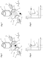
- a gluing device 10 which serves to apply individual portions of glue to substrates not shown, such as blanks or material webs for the production and/or packaging of cigarettes or other smokable articles.
- the gluing device 10 comprises (at least) one glue valve 11 with glue valve outlet nozzle 12, which can be controlled by means of a control device (not shown), is usually but not necessarily designed as a solenoid valve and is known in the art.
- Individual glue portions can be dispensed downwards onto the respective substrate from the glue valve outlet nozzle 12.
- (electrical) opening signals are sent to the glue valve 11 at certain times, which result in a closure member of the glue valve 11 that can be moved - for example by means of an electromagnet - from a closed position in which it closes a (lower) nozzle opening 12a of the glue valve outlet nozzle 12, to an open position in which it releases the nozzle opening so that individual glue portions 13 can be dispensed downwards from the opening.
- the closure element By means of a return element, for example by means of a spring or by means of repelling permanent magnets, the closure element is then automatically moved back into the closed position and held there.
- a return element for example by means of a spring or by means of repelling permanent magnets, the closure element is then automatically moved back into the closed position and held there.
- the exact design of the glue valve is not important.
- the gluing device 10 is usually integrated into a higher-level production process, for example in a packaging process. Accordingly, the glue valve opening signals are synchronized with the packaging process. For example, the glue valve 11 is opened or closed again synchronously with or in a higher-level machine cycle of a machine to which the glue valve 11 is assigned.
- the gluing device 10 often includes several glue valves 11 arranged next to one another. However, this does not have to be the case.
- the glue valve 11 may malfunction.
- the glue valve outlet nozzle may gradually become contaminated with glue residue.
- the dispensed glue portions 13 may also gradually change accordingly. In extreme cases, the contamination may lead to no more glue portions 13 being able to be dispensed.
- the gluing device 10 has a monitoring device 14 with which the respective glue delivery during the production process is automatically monitored in a special way.
- the monitoring device 14 has, on the one hand, a capacitor 15 arranged below the glue outlet nozzle 12 (open from top to bottom), which can build up a capacitor field 16 that runs transversely to the glue outlet direction or is oriented horizontally.
- the capacitor 15 has two (flat) capacitor plates 15a and 15b arranged at a distance from one another, parallel or in parallel vertical planes.
- the capacitor 15 or its capacitor plates 15a, 15b are positioned in such a way that the capacitor field 16 is arranged between them in such a way that glue portions 13, which properly emerge from the glue valve 11 or from the glue outlet nozzle 12, on their way down to the substrate must necessarily enter the capacitor field 16, pass through it and exit it again before they then fall onto the substrate arranged below the capacitor plates 15a, 15b or below the capacitor field 16.
- the capacitor field 16 is preferably aligned transversely to the direction of movement of the glue portion.
- the monitoring device 14 also has suitable measuring electronics 17, which is connected to the capacitor 15.
- a measuring voltage U can be applied to the capacitor plates 15a, 15b.
- a suitable alternating voltage is applied for this purpose so that the orientation of the capacitor field 16 changes accordingly.
- the measuring electronics in this case comprise a frequency generator 17a.
- the actual voltage between the capacitor plates 15a, 15b, which can be influenced by the glue portions 16 passing through the capacitor field 16, is recorded as the actual measurement signal.
- the measuring electronics 17 further comprises a filter circuit 17b, which processes the actual measurement signal in a suitable manner, in particular freeing it from alternating voltage components generated by the frequency generator 17a.
- the measuring electronics 17 can also be designed differently.
- a frequency generator 17a could be dispensed with and operation could be carried out with direct current.
- the filter circuit 17b could also be omitted.
- the monitoring device 14 in particular the capacitor field 16 and the measuring electronics 17, is designed in such a way that portions of glue 13 that pass through the field 16 lead to a characteristic change in the measuring signal recorded by the measuring electronics or generate a characteristic measuring signal.
- a control signal 19 or an opening signal for opening the glue valve 11 is shown in the diagram.
- the opening signal 19 of the glue valve 11 at time t 1 causes a characteristic signal change S 1 in the measurement signal 18.
- the background is that the electromagnetic field of the electromagnet of the glue valve 11 leads to a first disturbance of the capacitor field 16, which is reflected in a change in the capacitance of the capacitor 15 and, as a result, in the characteristic signal change S 1 .
- a characteristic signal change S 2 can be seen in the measurement signal 18, which is due to the disturbance of the capacitor field 16 by the glue portion 13 passing through the capacitor field 16. According to the invention, this disturbance or the characteristic signal change S 2 is recognized as part of the (automatic) evaluation of the measurement signal U.
- the measurement signal U can be evaluated, for example, using appropriate evaluation electronics (or a corresponding evaluation computer) of the monitoring device 14.
- the characteristic signal disturbance S 2 occurred within a predetermined time window that is set in the monitoring device 14.
- the monitoring device generates an error signal that can be displayed on a screen, for example.
- the gluing device 10 is opposite the Fig.1 has been modified somewhat. Namely, in that the condenser 15 arranged under the glue outlet nozzle 12 has been moved closer to the glue valve outlet nozzle 12.
- the distance between the glue valve outlet nozzle 12 or the nozzle opening 12a on the one hand and the capacitor 15 or the capacitor field 16 on the other hand is smaller than in Fig.1 .
- the glue portion 13 is in this case connected to the same electrical reference potential as the frequency generator 17a. This results in a capacitive coupling which causes a stronger disturbance of the capacitor field 16 and thus a stronger or more pronounced characteristic signal change S 2 than in the embodiment according to Fig.1 .
- the signal change S 2 naturally also occurs at an earlier time t 2 than in the embodiment Fig. 1 , since the drop of glue 13 enters the capacitor field 16 earlier.
- the gluing device 10 in the 5 and 7 corresponds to that of Fig. 3 . It is easy to see that different, in the Fig. 5 or 7 shown spatial positions of the dispensed glue portion 13 relative to the capacitor field 16 correspond to different measurement signal values at corresponding assigned times t 2 : In Fig. 5 At time t 2 , the drop of glue 13 arrives essentially in the middle of the capacitor field 16 on its way through the capacitor field 16 (from top to bottom). Based on the measurement signal 18, this corresponds to a position at the end of the rising edge of the characteristic signal change S2.
- Fig.7 In contrast, the glue drop 13 has already completely passed through the capacitor field 16 at the time t 2 and has exited the capacitor field 16 below it. This corresponds to a correspondingly later position on the measuring signal 18 and a measuring signal value that corresponds to a measuring signal value in an undisturbed state of the capacitor 15 (outside the characteristic signal change S 2 ).
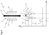
- Fig.9 symbolizes that a or the measuring signal 18 can be evaluated in different ways according to the invention.
- the characteristic signal change S 2 comprises in Fig.9
- t s and t 3 there are two low points, which correspond to the beginning (t 2 ) of a rising side edge of the signal change S 2 or the end (t 3 ) of a falling side edge.
- the time t 2 corresponds to the time at which the glue portion 13 enters the capacitor field 16
- the time t 3 corresponds to the time at which the glue portion 13 exits the capacitor field 16.
- envelope curves 20a, 20b are used for this purpose, with which the measurement signal 18 and in particular the characteristic signal change S 2 are compared.
- a signal curve 18 which is located between one or the upper envelope 20a and one or the lower envelope 20b, cf. Fig.9 , is evaluated by the monitoring device 14 as correct or error-free.
- the measurement signal 18 or the characteristic measurement signal change S 2 leaves the area between the envelope limit curves 20a, 20b or exceeds the upper envelope limit curve 20a or falls below the lower envelope limit curve 20b, this could be evaluated by the monitoring device as an error and an error signal could be generated.
- Such an error could, for example, indicate poor quality of the glue portion 13. For example, due to contamination of the glue outlet nozzle 12, which reduces the quality of the glue portion 13 dispensed, but does not lead to the glue dispensing of glue drops 13 coming to a complete standstill.
- the length of the respective glue portion 13 could be calculated from the time difference between entry t 2 and exit t 3 of the glue portion 13 from the capacitor field 16.
- the speed of the glue portion 13 would first have to be determined. This would be possible without any problems since the distance between the glue valve outlet nozzle 12 and the capacitor field 16 is known.
- the time difference t 1 -t 2 is known between the actuation of the glue valve 11 and the entry of the glue portion 13 into the capacitor field 16. The speed of the glue portion 13 can then be calculated from this.
- the respective length of the glue portion 13 can then be determined.
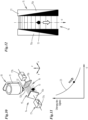
- a gluing device 10 is shown as an example, in which the capacitor field 16 is inhomogeneous, namely decreasing in strength from top to bottom.
- the capacitor plates 15a, 15b are not aligned in parallel, spaced-apart vertical planes, but are placed at an angle to one another, so that the distance between them - in the present case - increases from top to bottom.
- the distance decreases from top to bottom, so that the capacitor field strength increases accordingly from top to bottom.
- capacitor 15, as shown in Fig. 12 is shown.
- the capacitor plates 15a, 15b are arranged in parallel. However, they are made of a composite material.
- An electrically active capacitor material 21 of the capacitor plates 15a, 15b continuously decreases in its respective strength from top to bottom (or, if necessary, conversely, from top to bottom), so that the result is the same field that becomes weaker from top to bottom as at the capacitor 15 the Fig. 10 results.
- the illustrated inhomogeneity of the capacitor field 16 results in characteristic signal changes of the respective measuring signal 18 when passing the respective glue portion 13, which are position-dependent.
- the curve 23 represents the strength of the respective characteristic measurement signal change 18 or the strength of the disturbance of the capacitor field 16 as a function of the coordinate z or the penetration depth of the glue portion 13 into the capacitor field 16 (from top to bottom). Based on these relationships, it is possible according to the invention to determine the respective current position of the respective glue portion 13 within the capacitor field 16 (in this case uniaxial).
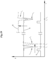
- FIG. 13 An embodiment of the gluing device 10 is shown, in which two capacitor fields 16a, 16b are constructed below the glue outlet nozzle 12 of the glue valve 11 for the biaxial determination of the position of the glue portion 13 dispensed.
- the capacitor field 16a is generated by a capacitor 15 with capacitor plates 15a, 15b.
- the capacitor field 16b through a capacitor 24 with capacitor plates 24a, 24b.
- the first capacitor field 16a runs above the second capacitor field 16b, in this case transversely to the capacitor field 16b.
- Both capacitor fields 16a, 16b are constructed inhomogeneously. In such a way that the electric field strength of both capacitor fields 16a, 16b increases perpendicular to the center axis of the glue valve outlet nozzle 12, but in directions perpendicular to each other.
- This structure can be used to detect the respective flight direction of the respective glue portion 13 after exiting the glue valve outlet nozzle 12. In particular, deviations of the flight direction from a/the target flight direction, which coincides with the center axis of the glue valve outlet nozzle 12, can be detected.
- Fig. 14 shows an example of a variant of a capacitor field 16, in which a pair of rings 15a ', 15b' of a ring capacitor 15 arranged in parallel, spaced planes (one above the other) is used to construct the same.
- the capacitor rings 15a ', 15b' lie one above the other in the z direction in horizontal planes spaced apart from one another and are each arranged with their longitudinal central axes coaxial or parallel to the longitudinal central axis of the glue outlet nozzle 12.
- the rings 15a', 15b' each have a conical geometry, whereby the material thickness thereof increases towards the outer edge.
- the strength of the electric field 16 reaches a maximum at the edge because of the larger mass there.
- a portion of glue 13 that penetrates such a field 16 causes a disturbance of the field 16 depending on the radial position within the two capacitor rings 15a', 15b'.
- the strength of such a disturbance or a corresponding characteristic measurement signal change is shown as a function of the radial distance r from the center of the respective capacitor rings 15a' or 15b'.
- a measurement signal 18 is shown, as it can be measured without such a reference capacitor in the respective capacitor 15 or 24 arranged under the glue valve 11.
- a measurement signal 18' is shown as it would be measured at the same time in a corresponding, neighboring reference capacitor or possibly in several reference capacitors.
- the measurement signal 18 ' represents the disturbing influences of the environment.
- glue residue can be deposited on the glue valve outlet nozzle 12. This can result in individual glue portions 13 detaching from or emerging from the glue valve outlet nozzle 12 at a later time than would be the case if the glue valve outlet nozzle 12 was free of errors or if the glue valve outlet nozzle 12 was not contaminated.
- the value of this time delay depends on the degree of contamination of the glue outlet nozzle.
- a first characteristic measurement signal change S 2 at time t 2 is shown, as it can occur in cycles when the glue valve 11 is working properly and is not dirty.
- a signal change S 2' is shown in dashed lines, which would occur at time t 2' after the glue valve 11 has been in operation for a certain time. From the time difference between t 2 and t 2' , the degree of contamination of the glue valve 11 can be determined using stored calibration values.
- Another scenario concerns the deposition of glue residues during operation of the monitoring device 14 on the respective capacitor plates/capacitor rings 15a, 15b; 15a', 15b' or 24a, 24b. Due to the relative proximity of the capacitor plates/capacitor rings 15a, 15b; 15a', 15b' or 24a, 24b to the glue valve outlet nozzle 12, glue splashes can reach the respective capacitor plate/capacitor ring 15a, 15b; 15a', 15b' or 24a, 24b. In particular, due to an oblique flight direction of the respective glue portion 13.
Landscapes
- Coating Apparatus (AREA)
Claims (15)
- Procédé de surveillance automatique d'une valve d'encollage (11) pendant le fonctionnement de celle-ci, de préférence dans le cadre du processus de fabrication et/ou d'emballage de cigarettes ou d'autres objets fumables, notamment afin de détecter une contamination de la buse de sortie de la valve d'encollage (11), procédé dans lequel, au-dessous de la buse de sortie de la valve d'encollage (11), un champ de condensateur électrique, qui est orienté en particulier transversalement ou sensiblement transversalement à la direction de déplacement de portion de colle, est constitué à l'aide d'un condensateur (15, 24) notamment stationnaire de sorte que des portions de colle (13) qui sortent de la valve d'encollage (11) doivent traverser le champ du condensateur et dans lequel une surveillance est effectuée par des techniques de mesure quant à la survenance d'une perturbation du champ de condensateur qui modifie la capacité du condensateur (15, 24), une détermination étant effectuée dans le cadre de la surveillance par des techniques de mesure quant à la perturbation du fonctionnement de la valve d'encollage (11), en particulier le débit d'encollage de celle-ci, au moins un paramètre caractérisant la portion de colle respective (13) ou la sortie de portion de colle respective, en particulier la longueur de la portion de colle (13), la vitesse de la portion de colle (13), la direction de déplacement de la portion de colle (13) ou la qualité de la portion de colle (13), étant déterminé dans le cadre de la surveillance par des techniques de mesure, caractérisé en ce qu'un champ de condensateur non homogène généré par un condensateur annulaire (15) est formé au-dessous de la buse de sortie de la valve d'encollage (12) de sorte que des portions de colle sortant de la valve d'encollage doivent traverser ce champ de condensateurs ou en ce que des champs de condensateurs non homogènes générés par des paires de plaques de condensateur et successifs dans la direction de déplacement des au moins deux portions de colle qui sortent de la buse de sortie de la valve d'encollage sont produits au-dessous de la buse de sortie de la valve d'encollage, de sorte que les portions de colle qui sortent de la valve d'encollage doivent traverser ces deux champs de condensateur, les deux champs de condensateurs s'étendant angulairement l'un par rapport à l'autre, en particulier suivant un angle de 90°.
- Procédé selon la revendication 1, caractérisé en ce que la surveillance par des techniques de mesure est effectuée après une ou chaque transmission d'un signal d'ouverture, destiné à ouvrir la valve d'encollage (11), à la valve d'encollage (11), notamment dans un intervalle de temps prédéterminé après le signal d'ouverture, et en ce que, dans le cas où aucune perturbation de ce type n'est détectée, un signal d'erreur est généré.
- Procédé selon la revendication 1 ou 2, caractérisé en ce que, dans le cadre de la surveillance par des techniques de mesure, un signal de mesure généré par les variations de capacité du condensateur (15, 24) ou un signal de mesure pouvant être influencé par de telles variation de capacité est détecté et évalué, en particulier une tension (électrique) appliquée au condensateur (15, 24).
- Procédé selon la revendication 3, caractérisé en ce qu'une tension alternative pouvant être influencée par les variations de capacité du condensateur (15, 24) est appliquée au condensateur (15, 24) et/ou en ce que le signal de mesure est filtré dans le cadre de son évaluation au moyen d'un module de filtrage électronique approprié.
- Procédé selon une ou plusieurs des revendications précédentes 3 à 4, caractérisé en ce que, dans le cadre de l'évaluation du signal de mesure, une détermination est effectuée, en particulier dans un intervalle de temps prédéterminé qui commence après la transmission d'un signal d'ouverture destiné à ouvrir la valve d'encollage à la valve d'encollage, de préférence dans un intervalle de temps de 3 millisecondes, quant au fait que le signal de mesure contient une variation de signal de mesure caractéristique qui peut être associée à une portion de colle (13) influant sur la capacité du condensateur, et en ce que, dans le cas où le signal de mesure ne contient pas une telle variation de signal de mesure caractéristique, une erreur est générée, et/ou en ce que, dans le cadre de l'évaluation du signal de mesure, l'intervalle de temps est déterminé entre un signal d'ouverture destiné à l'ouverture de la valve d'encollage (11) et une variation de signal de mesure caractéristique qui peut être associée à l'entrée d'une portion de colle (13) dans le champ de condensateur.
- Procédé selon la revendication 5, caractérisé en ce que la vitesse de la portion de colle (13) est calculée sur la base d'un intervalle de temps entre un signal d'ouverture de la valve d'encollage (11) et une variation de signal de mesure caractéristique pouvant être associée à l'entrée d'une portion de colle (13) dans le champ de condensateur et sur la base de la distance entre la buse de sortie de la valve d'encollage (12) et le champ de condensateur.
- Procédé selon une ou plusieurs des revendications précédentes 5 à 6, caractérisé en ce que, dans le cadre de l'évaluation du signal de mesure, l'intervalle de temps est déterminé entre une première variation de signal de mesure caractéristique qui peut être associée à l'entrée de la portion de colle (13) dans le champ du condensateur et une deuxième variation de signal de mesure caractéristique qui peut être associée à la sortie de la portion de colle (13) du champ de condensateur .
- Procédé selon les revendications 6 et 7, caractérisé en ce que, dans le cadre de l'évaluation du signal de mesure, la longueur de la portion de colle (13) est déterminée sur la base de cet intervalle de temps entre l'entrée et la sortie de la portion de colle (13) et sur la base de la vitesse de la portion de colle (13).
- Procédé selon une ou plusieurs des revendications précédentes 5 à 8, caractérisé en ce qu'au moins une valeur de signal de mesure d'une variation de signal de mesure caractéristique dans le signal de mesure qui peut être associée à une portion de colle (13) influant sur la capacité du condensateur (15, 24) est comparée à une valeur limite pour une telle variation de signal de mesure.
- Procédé selon une ou plusieurs des revendications précédentes, caractérisé en ce que le ou les champs de condensateur sont produits de manière à ce que des portions de colle qui sortent par erreur obliquement de la buse de sortie de la valve d'encollage et traversent le ou les champs de condensateur de manière correspondante obliquement, génèrent une variation de signal de mesure caractéristique qui est différente de celle des portions de colle qui sortent de la buse de sortie coaxialement à l'axe central longitudinal de celle-ci et qui traversent de façon correspondante perpendiculairement le ou les champs de condensateur.
- Procédé selon une ou plusieurs des revendications précédentes, caractérisé en ce que les champs de condensateur des paires de plaques de condensateur sont produits de manière à ce que l'intensité de champ électrique des champs de condensateur augmente perpendiculairement à l'axe central de la buse de sortie de valve d'encollage, mais dans des directions perpendiculaires entre elles, ou en ce que le champ de condensateur du condensateur annulaire est produit de manière à ce que l'intensité de champ électrique perpendiculaire à l'axe central longitudinal du condensateur annulaire (15) augmente dans toutes les directions radiales.
- Procédé selon la revendication 10 ou 11, caractérisé en ce que, dans le cadre de l'évaluation du signal de mesure, une détermination est effectuée quant au fait que la variation de signal de mesure caractéristique respective provient d'une portion de colle (13) qui sort obliquement de la buse de sortie, notamment par comparaison avec une variation de signal de mesure cible caractéristique, et en ce que, dans le cas où la variation de signal de mesure caractéristique provient d'une portion de colle (13) qui sort obliquement de la buse de sortie, un signal d'erreur est généré.
- Procédé selon une ou plusieurs des revendications précédentes, caractérisé en ce que le champ de condensateur au-dessous de la buse de sortie de colle s'étend transversalement à la direction de déplacement de la portion de colle (13) et est produit de façon non homogène de manière à ce que l'intensité de champ du champ de condensateur devienne plus forte ou plus faible notamment de manière continue dans la direction de déplacement des portions de colle (13) ou parallèlement à celle-ci de sorte que les portions de colle (13) qui traversent le champ de condensateur provoquent des variations de signal de mesure caractéristiques différentes en fonction de la profondeur de pénétration dans le champ de condensateur, la profondeur de pénétration de la portion de colle (13) qui est associée, ou qui provoque celle-ci, et qui est sortie de la buse de sortie de colle dans le champ de condensateur étant déterminée dans le cadre de l'évaluation du signal de mesure pour au moins une variation du signal de mesure caractéristique.
- Procédé selon une ou plusieurs des revendications précédentes, caractérisé en ce qu'un champ de condensateur de référence d'un condensateur de référence, associé au condensateur ou au champ de condensateur au-dessous de la buse de sortie de colle, est produit à proximité de la buse de sortie de colle de la valve d'encollage (13), c'est-à-dire de manière à ce qu'aucune portion de colle (13) ne sorte de la buse de sortie de colle et ne puisse traverser le champ de condensateur de référence, en ce que le champ de condensateur de référence est surveillé par des techniques de mesure pour déterminer si une perturbation d'environnement du champ de condensateur de référence modifiant la capacité du condensateur de référence se produit et en ce que, dans le cas où une telle perturbation d'environnement est détectée, cette perturbation d'environnement est éliminée par filtrage d'un signal de mesure qui est détecté à l'instant où se produit la perturbation d'environnement dans le cadre de la surveillance, par des techniques de mesure, du condensateur ou du champ de condensateur au-dessous de la buse de sortie de colle.
- Dispositif d'encollage de produits ou de matériau, en particulier de flans ou de bandes de matériau, pour fabriquer et/ou emballer des cigarettes ou d'autres objets pouvant être fumés, ledit dispositif comprenant au moins une valve d'encollage (11) destinée à appliquer des portions de colle (13) sur le produit ou le matériau, un module de surveillance (14) destiné à surveiller automatiquement la valve d'encollage (11) pendant le fonctionnement de celle-ci, notamment afin de détecter une contamination de la buse de sortie de la valve d'encollage (11), le module de surveillance (14) comportant un condensateur disposé au-dessous de la buse de sortie de la valve d'encollage (11) et permettant de produire un champ de condensateur électrique orienté en particulier transversalement ou sensiblement transversalement à la direction de déplacement de portion de colle de la valve d'encollage (11) de sorte que les portions de colle (13) sortant de la valve d'encollage (11) doivent traverser le champ du condensateur, le dispositif de surveillance (14) permettant de surveiller si une perturbation du champ de condensateur se produit qui modifie la capacité du condensateur et une détermination étant effectuée dans le cadre de la surveillance par des techniques de mesure quant la perturbation du fonctionnement de la valve d'encollage (11), en particulier du débit de colle de celle-ci, et au moins un paramètre qui caractérise la portion de colle respective (13) ou la sortie de la portion de colle respective, en particulier la longueur de la portion de colle (13), la vitesse de la portion de colle (13), la direction de déplacement de la portion de colle (13) ou la qualité de la portion de colle (13), pour être déterminé dans le cadre de la surveillance par des techniques de mesure,
caractérisé en ce qu'un champ de condensateur non-homogène généré par un condensateur annulaire (15) est produit au-dessous de la buse de sortie de valve d'encollage (12) de sorte que des portions de colle sortant de la valve d'encollage doivent traverser ce champ de condensateurs ou en ce que des champs de condensateurs non homogènes générés par des paires de plaques de condensateur et successifs dans la direction de déplacement des au moins deux portions de colle qui sortent de la buse de sortie de valve d'encollage peuvent être produits au-dessous de la buse de sortie de valve d'encollage de sorte que des portions de colle qui sortent de la valve d'encollage doivent traverser ces deux champs de condensateur, les deux champs de condensateurs s'étendant angulairement l'un par rapport à l'autre, en particulier suivant un angle de 90°.
Applications Claiming Priority (2)
| Application Number | Priority Date | Filing Date | Title |
|---|---|---|---|
| DE102018002129.8A DE102018002129A1 (de) | 2018-03-16 | 2018-03-16 | Verfahren zur automatischen Überwachung der Leimabgabe eines Leimventils |
| PCT/EP2019/056476 WO2019175343A1 (fr) | 2018-03-16 | 2019-03-14 | Procédé pour la surveillance automatique de la distribution de colle d'une vanne à colle |
Publications (2)
| Publication Number | Publication Date |
|---|---|
| EP3765207A1 EP3765207A1 (fr) | 2021-01-20 |
| EP3765207B1 true EP3765207B1 (fr) | 2024-04-03 |
Family
ID=65812316
Family Applications (1)
| Application Number | Title | Priority Date | Filing Date |
|---|---|---|---|
| EP19711575.1A Active EP3765207B1 (fr) | 2018-03-16 | 2019-03-14 | Procédé de surveillance automatique de la délivrance de colle depuis une soupape |
Country Status (3)
| Country | Link |
|---|---|
| EP (1) | EP3765207B1 (fr) |
| DE (1) | DE102018002129A1 (fr) |
| WO (1) | WO2019175343A1 (fr) |
Families Citing this family (4)
| Publication number | Priority date | Publication date | Assignee | Title |
|---|---|---|---|---|
| CN111085359B (zh) * | 2019-12-31 | 2021-06-15 | 北京航空航天大学 | 用于喷涂的流体引导装置、喷涂系统及喷涂方法 |
| CN111229548A (zh) * | 2020-03-17 | 2020-06-05 | 欣辰卓锐(苏州)智能装备有限公司 | 一种基于流水线的自动跟踪点胶系统 |
| CN111751373A (zh) * | 2020-07-03 | 2020-10-09 | 深圳市轴心自控技术有限公司 | 一种用于点胶设备的防挂胶检测方法 |
| CN115634803B (zh) * | 2022-10-31 | 2023-10-13 | 江西中烟工业有限责任公司 | 一种颗粒型加热不燃烧卷烟封口罐装生产线中的涂胶装置 |
Family Cites Families (8)
| Publication number | Priority date | Publication date | Assignee | Title |
|---|---|---|---|---|
| DE3225554A1 (de) * | 1982-07-08 | 1984-01-12 | Robert Bosch Gmbh, 7000 Stuttgart | Messeinrichtung fuer fluidstrahlen |
| DE3722059C1 (en) * | 1987-07-03 | 1988-08-25 | Bosch Gmbh Robert | Measuring device for fluid jets |
| DE3934852A1 (de) * | 1989-10-19 | 1991-04-25 | Macon Gmbh Klebstoff Auftragsg | Einrichtung zur ueberwachung eines auftrags auf ein substrat |
| DE4304678C1 (de) * | 1993-02-16 | 1994-07-21 | Kurandt System Gmbh | Verfahren zum kontinuierlichen Abtasten und Überprüfen von Spurauftragungen auf einer bewegten Unterlage und Vorrichtung zur Durchführung des Verfahrens |
| DE19842266B4 (de) * | 1998-09-15 | 2004-11-04 | Windmöller & Hölscher Kg | Verfahren zum Steuern von Klebstoffaufträgen auf kontinuierlich bewegte Sack- oder Beutelwerkstücke |
| DE10032205A1 (de) * | 2000-07-01 | 2002-01-10 | Juergen Hosbach | Verfahren zum Erkennen von Massenveränderungen längs eines Produktes |
| DE102015117248A1 (de) * | 2015-10-09 | 2017-04-13 | Vermes Microdispensing GmbH | Tropfendetektionseinrichtung |
| DE102016014951A1 (de) * | 2016-12-14 | 2018-06-14 | Dürr Systems Ag | Beschichtungseinrichtung und zugehöriges Betriebsverfahren |
-
2018
- 2018-03-16 DE DE102018002129.8A patent/DE102018002129A1/de not_active Withdrawn
-
2019
- 2019-03-14 EP EP19711575.1A patent/EP3765207B1/fr active Active
- 2019-03-14 WO PCT/EP2019/056476 patent/WO2019175343A1/fr not_active Ceased
Also Published As
| Publication number | Publication date |
|---|---|
| WO2019175343A1 (fr) | 2019-09-19 |
| EP3765207A1 (fr) | 2021-01-20 |
| DE102018002129A1 (de) | 2019-09-19 |
Similar Documents
| Publication | Publication Date | Title |
|---|---|---|
| EP3765207B1 (fr) | Procédé de surveillance automatique de la délivrance de colle depuis une soupape | |
| EP3523053B1 (fr) | Dispositif de revêtement et méthode de revêtement correspondante | |
| DE4229834C2 (de) | Verfahren und Einrichtung zum elektrischen Verarbeiten von Vakuumdruckinformation für eine Vakuumeinheit | |
| EP2589437B1 (fr) | Procédé de détection des pannes et de mesure de la course de soupape d'une vanne à colle | |
| EP2712680B1 (fr) | Procédé de revêtement d'une pièce à usiner avec de la poudre au moyen d'un pistolet de pulvérisation de poudre et installation de revêtement de poudre | |
| EP3263235A1 (fr) | Dispositif et procédé pour transporter et examiner des produits à traiter défilant à vitesse élevée | |
| DE3347459C2 (fr) | ||
| EP2047118B1 (fr) | Procédé de localisation de défaut et de diagnostic d'une installation fluidique | |
| DE102005063193A1 (de) | Vorrichtung und Verfahren zum Gruppieren von Stückgut | |
| EP2490649B1 (fr) | Machine et procédé permettant de remplir et de sceller des capsules composées en particulier de gélatine dure | |
| WO2007082575A9 (fr) | Procede et dispositif de surveillance d'une ligne de production | |
| EP3449207B1 (fr) | Dispositif et procédé pour mesurer un jet de laque pour le revêtement de cartes de circuits imprimés | |
| DE102017104953B4 (de) | Verfahren zum Betreiben einer Zündspule sowie Zündspule | |
| DE4210957A1 (de) | Verfahren zum Überwachen des Transportes von Druckerzeugnissen in einer drucktechnischen Maschine | |
| CH620655A5 (fr) | ||
| DE102022108575A1 (de) | Verfahren zum Betreiben eines Magnetventils | |
| DE102016101961A1 (de) | Sensoreinrichtung zum Detektieren von Materialfehlern und Verfahren hierzu | |
| DE4438507C2 (de) | Verfahren zur Überwachung eines elektronischen Schaltgerätes | |
| EP4204176B1 (fr) | Méthode et dispositif de soudage avec détection de contacts électriques au cours d'un procédé de soudage | |
| DE4003532C2 (de) | Kapazitive Doppelbogenkontrolleinrichtung | |
| DE102012023704A1 (de) | Verfahren und Vorrichtung zum Betreiben eines Leimventils | |
| DE2330782A1 (de) | Regelverfahren und regelvorrichtung | |
| EP4437305A1 (fr) | Procédé et dispositif de mesure d'une pièce en forme de plaque | |
| EP4249860B1 (fr) | Procédé de fonctionnement d'un dispositif de remplissage et dispositif de remplissage correspondant | |
| DE102023132200B3 (de) | Positionssensor und Verfahren mit einem Positionssensor |
Legal Events
| Date | Code | Title | Description |
|---|---|---|---|
| STAA | Information on the status of an ep patent application or granted ep patent |
Free format text: STATUS: UNKNOWN |
|
| STAA | Information on the status of an ep patent application or granted ep patent |
Free format text: STATUS: THE INTERNATIONAL PUBLICATION HAS BEEN MADE |
|
| PUAI | Public reference made under article 153(3) epc to a published international application that has entered the european phase |
Free format text: ORIGINAL CODE: 0009012 |
|
| STAA | Information on the status of an ep patent application or granted ep patent |
Free format text: STATUS: REQUEST FOR EXAMINATION WAS MADE |
|
| 17P | Request for examination filed |
Effective date: 20200916 |
|
| AK | Designated contracting states |
Kind code of ref document: A1 Designated state(s): AL AT BE BG CH CY CZ DE DK EE ES FI FR GB GR HR HU IE IS IT LI LT LU LV MC MK MT NL NO PL PT RO RS SE SI SK SM TR |
|
| AX | Request for extension of the european patent |
Extension state: BA ME |
|
| DAV | Request for validation of the european patent (deleted) | ||
| DAX | Request for extension of the european patent (deleted) | ||
| STAA | Information on the status of an ep patent application or granted ep patent |
Free format text: STATUS: EXAMINATION IS IN PROGRESS |
|
| 17Q | First examination report despatched |
Effective date: 20220603 |
|
| GRAP | Despatch of communication of intention to grant a patent |
Free format text: ORIGINAL CODE: EPIDOSNIGR1 |
|
| STAA | Information on the status of an ep patent application or granted ep patent |
Free format text: STATUS: GRANT OF PATENT IS INTENDED |
|
| RIC1 | Information provided on ipc code assigned before grant |
Ipc: B05B 12/00 20180101ALN20230623BHEP Ipc: B05C 11/10 20060101ALI20230623BHEP Ipc: B05C 5/02 20060101ALI20230623BHEP Ipc: B05B 15/50 20180101ALI20230623BHEP Ipc: B05B 12/08 20060101AFI20230623BHEP |
|
| INTG | Intention to grant announced |
Effective date: 20230713 |
|
| GRAJ | Information related to disapproval of communication of intention to grant by the applicant or resumption of examination proceedings by the epo deleted |
Free format text: ORIGINAL CODE: EPIDOSDIGR1 |
|
| STAA | Information on the status of an ep patent application or granted ep patent |
Free format text: STATUS: EXAMINATION IS IN PROGRESS |
|
| GRAP | Despatch of communication of intention to grant a patent |
Free format text: ORIGINAL CODE: EPIDOSNIGR1 |
|
| STAA | Information on the status of an ep patent application or granted ep patent |
Free format text: STATUS: GRANT OF PATENT IS INTENDED |
|
| INTC | Intention to grant announced (deleted) | ||
| RIC1 | Information provided on ipc code assigned before grant |
Ipc: B05B 12/00 20180101ALN20230918BHEP Ipc: B05C 11/10 20060101ALI20230918BHEP Ipc: B05C 5/02 20060101ALI20230918BHEP Ipc: B05B 15/50 20180101ALI20230918BHEP Ipc: B05B 12/08 20060101AFI20230918BHEP |
|
| INTG | Intention to grant announced |
Effective date: 20231018 |
|
| GRAS | Grant fee paid |
Free format text: ORIGINAL CODE: EPIDOSNIGR3 |
|
| GRAA | (expected) grant |
Free format text: ORIGINAL CODE: 0009210 |
|
| STAA | Information on the status of an ep patent application or granted ep patent |
Free format text: STATUS: THE PATENT HAS BEEN GRANTED |
|
| AK | Designated contracting states |
Kind code of ref document: B1 Designated state(s): AL AT BE BG CH CY CZ DE DK EE ES FI FR GB GR HR HU IE IS IT LI LT LU LV MC MK MT NL NO PL PT RO RS SE SI SK SM TR |
|
| REG | Reference to a national code |
Ref country code: CH Ref legal event code: EP |
|
| REG | Reference to a national code |
Ref country code: IE Ref legal event code: FG4D Free format text: LANGUAGE OF EP DOCUMENT: GERMAN |
|
| REG | Reference to a national code |
Ref country code: DE Ref legal event code: R096 Ref document number: 502019010963 Country of ref document: DE |
|
| P01 | Opt-out of the competence of the unified patent court (upc) registered |
Effective date: 20240326 |
|
| REG | Reference to a national code |
Ref country code: LT Ref legal event code: MG9D |
|
| REG | Reference to a national code |
Ref country code: NL Ref legal event code: MP Effective date: 20240403 |
|
| PG25 | Lapsed in a contracting state [announced via postgrant information from national office to epo] |
Ref country code: NL Free format text: LAPSE BECAUSE OF FAILURE TO SUBMIT A TRANSLATION OF THE DESCRIPTION OR TO PAY THE FEE WITHIN THE PRESCRIBED TIME-LIMIT Effective date: 20240403 |
|
| PG25 | Lapsed in a contracting state [announced via postgrant information from national office to epo] |
Ref country code: NL Free format text: LAPSE BECAUSE OF FAILURE TO SUBMIT A TRANSLATION OF THE DESCRIPTION OR TO PAY THE FEE WITHIN THE PRESCRIBED TIME-LIMIT Effective date: 20240403 |
|
| PG25 | Lapsed in a contracting state [announced via postgrant information from national office to epo] |
Ref country code: IS Free format text: LAPSE BECAUSE OF FAILURE TO SUBMIT A TRANSLATION OF THE DESCRIPTION OR TO PAY THE FEE WITHIN THE PRESCRIBED TIME-LIMIT Effective date: 20240803 |
|
| PG25 | Lapsed in a contracting state [announced via postgrant information from national office to epo] |
Ref country code: BG Free format text: LAPSE BECAUSE OF FAILURE TO SUBMIT A TRANSLATION OF THE DESCRIPTION OR TO PAY THE FEE WITHIN THE PRESCRIBED TIME-LIMIT Effective date: 20240403 |
|
| PG25 | Lapsed in a contracting state [announced via postgrant information from national office to epo] |
Ref country code: HR Free format text: LAPSE BECAUSE OF FAILURE TO SUBMIT A TRANSLATION OF THE DESCRIPTION OR TO PAY THE FEE WITHIN THE PRESCRIBED TIME-LIMIT Effective date: 20240403 Ref country code: FI Free format text: LAPSE BECAUSE OF FAILURE TO SUBMIT A TRANSLATION OF THE DESCRIPTION OR TO PAY THE FEE WITHIN THE PRESCRIBED TIME-LIMIT Effective date: 20240403 |
|
| PG25 | Lapsed in a contracting state [announced via postgrant information from national office to epo] |
Ref country code: GR Free format text: LAPSE BECAUSE OF FAILURE TO SUBMIT A TRANSLATION OF THE DESCRIPTION OR TO PAY THE FEE WITHIN THE PRESCRIBED TIME-LIMIT Effective date: 20240704 |
|
| PG25 | Lapsed in a contracting state [announced via postgrant information from national office to epo] |
Ref country code: PT Free format text: LAPSE BECAUSE OF FAILURE TO SUBMIT A TRANSLATION OF THE DESCRIPTION OR TO PAY THE FEE WITHIN THE PRESCRIBED TIME-LIMIT Effective date: 20240805 |
|
| PG25 | Lapsed in a contracting state [announced via postgrant information from national office to epo] |
Ref country code: ES Free format text: LAPSE BECAUSE OF FAILURE TO SUBMIT A TRANSLATION OF THE DESCRIPTION OR TO PAY THE FEE WITHIN THE PRESCRIBED TIME-LIMIT Effective date: 20240403 |
|
| PG25 | Lapsed in a contracting state [announced via postgrant information from national office to epo] |
Ref country code: CZ Free format text: LAPSE BECAUSE OF FAILURE TO SUBMIT A TRANSLATION OF THE DESCRIPTION OR TO PAY THE FEE WITHIN THE PRESCRIBED TIME-LIMIT Effective date: 20240403 |
|
| PG25 | Lapsed in a contracting state [announced via postgrant information from national office to epo] |
Ref country code: PL Free format text: LAPSE BECAUSE OF FAILURE TO SUBMIT A TRANSLATION OF THE DESCRIPTION OR TO PAY THE FEE WITHIN THE PRESCRIBED TIME-LIMIT Effective date: 20240403 |
|
| PG25 | Lapsed in a contracting state [announced via postgrant information from national office to epo] |
Ref country code: LV Free format text: LAPSE BECAUSE OF FAILURE TO SUBMIT A TRANSLATION OF THE DESCRIPTION OR TO PAY THE FEE WITHIN THE PRESCRIBED TIME-LIMIT Effective date: 20240403 |
|
| PG25 | Lapsed in a contracting state [announced via postgrant information from national office to epo] |
Ref country code: PT Free format text: LAPSE BECAUSE OF FAILURE TO SUBMIT A TRANSLATION OF THE DESCRIPTION OR TO PAY THE FEE WITHIN THE PRESCRIBED TIME-LIMIT Effective date: 20240805 Ref country code: PL Free format text: LAPSE BECAUSE OF FAILURE TO SUBMIT A TRANSLATION OF THE DESCRIPTION OR TO PAY THE FEE WITHIN THE PRESCRIBED TIME-LIMIT Effective date: 20240403 Ref country code: NO Free format text: LAPSE BECAUSE OF FAILURE TO SUBMIT A TRANSLATION OF THE DESCRIPTION OR TO PAY THE FEE WITHIN THE PRESCRIBED TIME-LIMIT Effective date: 20240703 Ref country code: LV Free format text: LAPSE BECAUSE OF FAILURE TO SUBMIT A TRANSLATION OF THE DESCRIPTION OR TO PAY THE FEE WITHIN THE PRESCRIBED TIME-LIMIT Effective date: 20240403 Ref country code: IS Free format text: LAPSE BECAUSE OF FAILURE TO SUBMIT A TRANSLATION OF THE DESCRIPTION OR TO PAY THE FEE WITHIN THE PRESCRIBED TIME-LIMIT Effective date: 20240803 Ref country code: HR Free format text: LAPSE BECAUSE OF FAILURE TO SUBMIT A TRANSLATION OF THE DESCRIPTION OR TO PAY THE FEE WITHIN THE PRESCRIBED TIME-LIMIT Effective date: 20240403 Ref country code: GR Free format text: LAPSE BECAUSE OF FAILURE TO SUBMIT A TRANSLATION OF THE DESCRIPTION OR TO PAY THE FEE WITHIN THE PRESCRIBED TIME-LIMIT Effective date: 20240704 Ref country code: FI Free format text: LAPSE BECAUSE OF FAILURE TO SUBMIT A TRANSLATION OF THE DESCRIPTION OR TO PAY THE FEE WITHIN THE PRESCRIBED TIME-LIMIT Effective date: 20240403 Ref country code: ES Free format text: LAPSE BECAUSE OF FAILURE TO SUBMIT A TRANSLATION OF THE DESCRIPTION OR TO PAY THE FEE WITHIN THE PRESCRIBED TIME-LIMIT Effective date: 20240403 Ref country code: CZ Free format text: LAPSE BECAUSE OF FAILURE TO SUBMIT A TRANSLATION OF THE DESCRIPTION OR TO PAY THE FEE WITHIN THE PRESCRIBED TIME-LIMIT Effective date: 20240403 Ref country code: BG Free format text: LAPSE BECAUSE OF FAILURE TO SUBMIT A TRANSLATION OF THE DESCRIPTION OR TO PAY THE FEE WITHIN THE PRESCRIBED TIME-LIMIT Effective date: 20240403 Ref country code: RS Free format text: LAPSE BECAUSE OF FAILURE TO SUBMIT A TRANSLATION OF THE DESCRIPTION OR TO PAY THE FEE WITHIN THE PRESCRIBED TIME-LIMIT Effective date: 20240703 |
|
| REG | Reference to a national code |
Ref country code: DE Ref legal event code: R097 Ref document number: 502019010963 Country of ref document: DE |
|
| PG25 | Lapsed in a contracting state [announced via postgrant information from national office to epo] |
Ref country code: DK Free format text: LAPSE BECAUSE OF FAILURE TO SUBMIT A TRANSLATION OF THE DESCRIPTION OR TO PAY THE FEE WITHIN THE PRESCRIBED TIME-LIMIT Effective date: 20240403 |
|
| PG25 | Lapsed in a contracting state [announced via postgrant information from national office to epo] |
Ref country code: EE Free format text: LAPSE BECAUSE OF FAILURE TO SUBMIT A TRANSLATION OF THE DESCRIPTION OR TO PAY THE FEE WITHIN THE PRESCRIBED TIME-LIMIT Effective date: 20240403 |
|
| PG25 | Lapsed in a contracting state [announced via postgrant information from national office to epo] |
Ref country code: RO Free format text: LAPSE BECAUSE OF FAILURE TO SUBMIT A TRANSLATION OF THE DESCRIPTION OR TO PAY THE FEE WITHIN THE PRESCRIBED TIME-LIMIT Effective date: 20240403 Ref country code: SK Free format text: LAPSE BECAUSE OF FAILURE TO SUBMIT A TRANSLATION OF THE DESCRIPTION OR TO PAY THE FEE WITHIN THE PRESCRIBED TIME-LIMIT Effective date: 20240403 |
|
| PG25 | Lapsed in a contracting state [announced via postgrant information from national office to epo] |
Ref country code: SM Free format text: LAPSE BECAUSE OF FAILURE TO SUBMIT A TRANSLATION OF THE DESCRIPTION OR TO PAY THE FEE WITHIN THE PRESCRIBED TIME-LIMIT Effective date: 20240403 |
|
| PG25 | Lapsed in a contracting state [announced via postgrant information from national office to epo] |
Ref country code: SM Free format text: LAPSE BECAUSE OF FAILURE TO SUBMIT A TRANSLATION OF THE DESCRIPTION OR TO PAY THE FEE WITHIN THE PRESCRIBED TIME-LIMIT Effective date: 20240403 Ref country code: SK Free format text: LAPSE BECAUSE OF FAILURE TO SUBMIT A TRANSLATION OF THE DESCRIPTION OR TO PAY THE FEE WITHIN THE PRESCRIBED TIME-LIMIT Effective date: 20240403 Ref country code: RO Free format text: LAPSE BECAUSE OF FAILURE TO SUBMIT A TRANSLATION OF THE DESCRIPTION OR TO PAY THE FEE WITHIN THE PRESCRIBED TIME-LIMIT Effective date: 20240403 Ref country code: EE Free format text: LAPSE BECAUSE OF FAILURE TO SUBMIT A TRANSLATION OF THE DESCRIPTION OR TO PAY THE FEE WITHIN THE PRESCRIBED TIME-LIMIT Effective date: 20240403 Ref country code: DK Free format text: LAPSE BECAUSE OF FAILURE TO SUBMIT A TRANSLATION OF THE DESCRIPTION OR TO PAY THE FEE WITHIN THE PRESCRIBED TIME-LIMIT Effective date: 20240403 |
|
| PLBE | No opposition filed within time limit |
Free format text: ORIGINAL CODE: 0009261 |
|
| STAA | Information on the status of an ep patent application or granted ep patent |
Free format text: STATUS: NO OPPOSITION FILED WITHIN TIME LIMIT |
|
| 26N | No opposition filed |
Effective date: 20250106 |
|
| PG25 | Lapsed in a contracting state [announced via postgrant information from national office to epo] |
Ref country code: SI Free format text: LAPSE BECAUSE OF FAILURE TO SUBMIT A TRANSLATION OF THE DESCRIPTION OR TO PAY THE FEE WITHIN THE PRESCRIBED TIME-LIMIT Effective date: 20240403 |
|
| PG25 | Lapsed in a contracting state [announced via postgrant information from national office to epo] |
Ref country code: SE Free format text: LAPSE BECAUSE OF FAILURE TO SUBMIT A TRANSLATION OF THE DESCRIPTION OR TO PAY THE FEE WITHIN THE PRESCRIBED TIME-LIMIT Effective date: 20240403 |
|
| PG25 | Lapsed in a contracting state [announced via postgrant information from national office to epo] |
Ref country code: MC Free format text: LAPSE BECAUSE OF FAILURE TO SUBMIT A TRANSLATION OF THE DESCRIPTION OR TO PAY THE FEE WITHIN THE PRESCRIBED TIME-LIMIT Effective date: 20240403 |
|
| REG | Reference to a national code |
Ref country code: CH Ref legal event code: H13 Free format text: ST27 STATUS EVENT CODE: U-0-0-H10-H13 (AS PROVIDED BY THE NATIONAL OFFICE) Effective date: 20251023 |
|
| PG25 | Lapsed in a contracting state [announced via postgrant information from national office to epo] |
Ref country code: LU Free format text: LAPSE BECAUSE OF NON-PAYMENT OF DUE FEES Effective date: 20250314 |
|
| GBPC | Gb: european patent ceased through non-payment of renewal fee |
Effective date: 20250314 |
|
| REG | Reference to a national code |
Ref country code: BE Ref legal event code: MM Effective date: 20250331 |
|
| PG25 | Lapsed in a contracting state [announced via postgrant information from national office to epo] |
Ref country code: GB Free format text: LAPSE BECAUSE OF NON-PAYMENT OF DUE FEES Effective date: 20250314 |
|
| PG25 | Lapsed in a contracting state [announced via postgrant information from national office to epo] |
Ref country code: FR Free format text: LAPSE BECAUSE OF NON-PAYMENT OF DUE FEES Effective date: 20250331 Ref country code: IT Free format text: LAPSE BECAUSE OF NON-PAYMENT OF DUE FEES Effective date: 20250314 |
|
| PG25 | Lapsed in a contracting state [announced via postgrant information from national office to epo] |
Ref country code: BE Free format text: LAPSE BECAUSE OF NON-PAYMENT OF DUE FEES Effective date: 20250331 |
|
| PG25 | Lapsed in a contracting state [announced via postgrant information from national office to epo] |
Ref country code: CH Free format text: LAPSE BECAUSE OF NON-PAYMENT OF DUE FEES Effective date: 20250331 |
|
| PG25 | Lapsed in a contracting state [announced via postgrant information from national office to epo] |
Ref country code: IE Free format text: LAPSE BECAUSE OF NON-PAYMENT OF DUE FEES Effective date: 20250314 |
|
| PGFP | Annual fee paid to national office [announced via postgrant information from national office to epo] |
Ref country code: DE Payment date: 20260227 Year of fee payment: 8 |
|
| PG25 | Lapsed in a contracting state [announced via postgrant information from national office to epo] |
Ref country code: IT Free format text: LAPSE BECAUSE OF NON-PAYMENT OF DUE FEES Effective date: 20250314 |
|
| PGFP | Annual fee paid to national office [announced via postgrant information from national office to epo] |
Ref country code: IT Payment date: 20250331 Year of fee payment: 7 |
|
| PGRI | Patent reinstated in contracting state [announced from national office to epo] |
Ref country code: IT Effective date: 20250731 |