EP3765239B1 - Régulation de vitesse avec rectification assistée par robot - Google Patents
Régulation de vitesse avec rectification assistée par robot Download PDFInfo
- Publication number
- EP3765239B1 EP3765239B1 EP19711320.2A EP19711320A EP3765239B1 EP 3765239 B1 EP3765239 B1 EP 3765239B1 EP 19711320 A EP19711320 A EP 19711320A EP 3765239 B1 EP3765239 B1 EP 3765239B1
- Authority
- EP
- European Patent Office
- Prior art keywords
- grinding
- contact
- speed
- grinding tool
- tool
- Prior art date
- Legal status (The legal status is an assumption and is not a legal conclusion. Google has not performed a legal analysis and makes no representation as to the accuracy of the status listed.)
- Active
Links
Images

Classifications
-
- B—PERFORMING OPERATIONS; TRANSPORTING
- B24—GRINDING; POLISHING
- B24B—MACHINES, DEVICES, OR PROCESSES FOR GRINDING OR POLISHING; DRESSING OR CONDITIONING OF ABRADING SURFACES; FEEDING OF GRINDING, POLISHING, OR LAPPING AGENTS
- B24B49/00—Measuring or gauging equipment for controlling the feed movement of the grinding tool or work; Arrangements of indicating or measuring equipment, e.g. for indicating the start of the grinding operation
- B24B49/006—Measuring or gauging equipment for controlling the feed movement of the grinding tool or work; Arrangements of indicating or measuring equipment, e.g. for indicating the start of the grinding operation taking regard of the speed
-
- B—PERFORMING OPERATIONS; TRANSPORTING
- B24—GRINDING; POLISHING
- B24B—MACHINES, DEVICES, OR PROCESSES FOR GRINDING OR POLISHING; DRESSING OR CONDITIONING OF ABRADING SURFACES; FEEDING OF GRINDING, POLISHING, OR LAPPING AGENTS
- B24B51/00—Arrangements for automatic control of a series of individual steps in grinding a workpiece
-
- B—PERFORMING OPERATIONS; TRANSPORTING
- B25—HAND TOOLS; PORTABLE POWER-DRIVEN TOOLS; MANIPULATORS
- B25J—MANIPULATORS; CHAMBERS PROVIDED WITH MANIPULATION DEVICES
- B25J11/00—Manipulators not otherwise provided for
- B25J11/005—Manipulators for mechanical processing tasks
- B25J11/0065—Polishing or grinding
-
- G—PHYSICS
- G05—CONTROLLING; REGULATING
- G05B—CONTROL OR REGULATING SYSTEMS IN GENERAL; FUNCTIONAL ELEMENTS OF SUCH SYSTEMS; MONITORING OR TESTING ARRANGEMENTS FOR SUCH SYSTEMS OR ELEMENTS
- G05B2219/00—Program-control systems
- G05B2219/30—Nc systems
- G05B2219/39—Robotics, robotics to robotics hand
- G05B2219/39321—Force control as function of position of tool
-
- G—PHYSICS
- G05—CONTROLLING; REGULATING
- G05B—CONTROL OR REGULATING SYSTEMS IN GENERAL; FUNCTIONAL ELEMENTS OF SUCH SYSTEMS; MONITORING OR TESTING ARRANGEMENTS FOR SUCH SYSTEMS OR ELEMENTS
- G05B2219/00—Program-control systems
- G05B2219/30—Nc systems
- G05B2219/45—Nc applications
- G05B2219/45058—Grinding, polishing robot
-
- G—PHYSICS
- G05—CONTROLLING; REGULATING
- G05B—CONTROL OR REGULATING SYSTEMS IN GENERAL; FUNCTIONAL ELEMENTS OF SUCH SYSTEMS; MONITORING OR TESTING ARRANGEMENTS FOR SUCH SYSTEMS OR ELEMENTS
- G05B2219/00—Program-control systems
- G05B2219/30—Nc systems
- G05B2219/45—Nc applications
- G05B2219/45161—Grinding machine
Definitions
- the present invention relates to a grinding machine for robot-assisted grinding and a robot-assisted method for grinding workpiece surfaces.
- a grinding machine e.g. an electrically operated grinding machine with a rotating grinding wheel as the grinding tool
- the grinding machine can be coupled in different ways to the so-called TCP ( Tool Center Point ) of the manipulator, so that the manipulator can adjust the position and orientation of the machine practically as desired.
- Industrial robots are usually position-controlled, which enables precise movement of the TCP along a desired trajectory.
- control of the process force is necessary in many applications, which is often difficult to achieve with sufficient accuracy using conventional industrial robots.
- a linear actuator that is smaller than the industrial robot can be arranged between the TCP of the manipulator and the grinding machine, which couples the TCP of the manipulator to the grinding machine.
- the linear actuator only controls the process force (i.e. the contact force between the grinding tool/grinding wheel and the workpiece) while the manipulator moves the grinding machine including the linear actuator (and thus the grinding tool) in a position-controlled manner along a predeterminable trajectory.
- Orbital or eccentric sanders can be used to machine surfaces.
- the sander is already switched on (i.e. the sanding wheel is rotating) when the sanding wheel comes into contact with the surface to be machined.
- the problem can arise that scratches or grooves are caused when the robot comes into contact with the surface to be machined.
- a human worker can avoid such undesirable effects by placing the sander particularly gently on the surface, which is not always possible to a sufficient extent with robot-assisted processes.
- the inventors have set themselves the task of developing an improved grinding device for robot-assisted grinding.
- the grinding device has a grinding machine coupled to a manipulator with a motor and a grinding tool driven by the motor, as well as a controller. This is designed to control the grinding machine in order to set the speed of the grinding tool, to position the grinding machine by means of the manipulator in order to contact the surface with the grinding tool while the grinding machine is operated at a first speed, and to detect contact between the grinding tool and the surface. In response to the detection of contact, the speed of the grinding tool is increased from the first speed to a second speed.
- the method comprises robot-assisted Positioning a grinding machine having a grinding tool such that the grinding tool contacts the surface while operating the grinding machine at a first speed and detecting contact between the grinding tool and the surface.
- the method further comprises, in response to detecting contact, increasing the speed of the grinding tool from the first speed to a second speed.
- a robot-assisted grinding device comprises a manipulator 1, for example an industrial robot, and a grinding machine 10 with a rotating grinding tool (eg an orbital grinding machine), which is connected to the so-called tool center point (TCP) of the manipulator 1 is coupled via a linear actuator 20.
- the manipulator can be constructed from four segments 2a, 2b, 2c and 2d, which are each connected via joints 3a, 3b and 3c.
- the first segment is usually rigidly connected to a foundation 41 (although this does not necessarily have to be the case).
- the joint 3c connects the segments 2c and 2d.
- the joint 3c can be 2-axis and enable rotation of the segment 2c about a horizontal axis of rotation (elevation angle) and a vertical axis of rotation (azimuth angle).
- the joint 3b connects the segments 2b and 2c and enables a pivoting movement of the segment 2b relative to the position of the segment 2c.
- the joint 3a connects the segments 2a and 2b.
- the joint 3a can be 2-axis and therefore (similar to the joint 3c) enable a pivoting movement in two directions.
- the TCP has a fixed relative position to the segment 2a, which usually also includes a rotary joint (not shown) that enables a rotary movement about a longitudinal axis A of the segment 2a (in Fig.1 drawn as a dot-dash line, corresponds to the axis of rotation of the grinding tool).
- a rotary joint (not shown) that enables a rotary movement about a longitudinal axis A of the segment 2a (in Fig.1 drawn as a dot-dash line, corresponds to the axis of rotation of the grinding tool).
- Each axis of a joint is assigned an actuator that can cause a rotary movement around the respective joint axis.
- the actuators in the joints are controlled by a robot controller 4 according to a robot program.
- Various industrial robots/manipulators and associated controllers are known per se and are therefore not explained further here.
- the manipulator 1 is usually position-controlled, ie the robot controller can determine the pose (location and orientation) of the TCP and move it along a predefined trajectory.
- the longitudinal axis of segment 2a on which the TCP lies is designated by A.
- the pose of the TCP also defines the pose of the grinding tool.
- actuator 20 is used to set the contact force (process force) between tool and workpiece 40 to a desired value during the grinding process.
- Direct force control by manipulator 1 is generally too imprecise for grinding applications, since the high mass inertia of segments 2a-c of manipulator 1 makes rapid compensation of force peaks (e.g. when placing the grinding tool on workpiece 40) practically impossible with conventional manipulators. For this reason, the robot controller is designed to regulate the pose (position and orientation) of the TCP of manipulator 1, while force control is carried out exclusively by actuator 20.
- the contact force F K (also referred to as process force) between the grinding tool and the workpiece 40 can be adjusted using the (linear) actuator 20 and a force control (which can be implemented in the controller 4, for example) so that the contact force F K (in the direction of the longitudinal axis A) between the grinding tool and the workpiece 40 corresponds to a predeterminable target value.
- the contact force is a reaction to the actuator force with which the linear actuator 20 presses onto the workpiece surface. If there is no contact between the workpiece 40 and the tool, the actuator 20 moves against an end stop (not shown because it is integrated in the actuator 20) due to the lack of contact force on the workpiece 40 and presses against it with a defined force.
- the actuator deflection is therefore maximum and the actuator is in an end position.
- the position control of the manipulator 1 (which can also be implemented in the controller 4) can work completely independently of the force control of the actuator 20.
- the actuator 20 is not responsible for positioning the grinding machine 10, but only for setting and maintaining the desired contact force F K during the grinding process and for detecting contact between the tool and the workpiece. Contact can be detected in a simple manner, for example, by the fact that the actuator has moved out of the end position (actuator deflection a is smaller than the maximum deflection a MAX ).
- the actuator can be a pneumatic actuator, e.g. a double-acting pneumatic cylinder.
- pneumatic actuators can also be used, such as bellows cylinders and air muscles.
- Electric direct drives can also be considered as an alternative.
- the direction of action of the actuator 20 does not necessarily have to coincide with the longitudinal axis A of the segment 2a of the manipulator.
- the force control can be implemented in a manner known per se with the aid of a control valve, a regulator (implemented in the controller 4) and a compressed air reservoir.
- Grinding machines usually have an extraction system to extract grinding dust.
- Fig.1 a connection 15 for a hose of a suction device is shown.
- the grinding machine 10 usually has an electric motor that drives the grinding wheel 11.
- the grinding wheel 11 is mounted on a carrier plate, which in turn is connected to the motor shaft of the electric motor.
- Asynchronous motors or synchronous motors can be considered as electric motors.
- Synchronous motors have the advantage that the speed does not change with the load (only the slip angle), whereas with asynchronous machines the speed decreases as the load increases.
- the load on the motor is essentially proportional to the contact force F K and the friction between the grinding wheel 11 and the surface of the workpiece 40 to be machined.
- the concepts described here can also be applied to grinding machines with pneumatic motors (compressed air motors). Grinding machines operated with compressed air can be built relatively compactly, as compressed air motors generally have a low power-to-weight ratio. Speed control is easily possible using a pressure control valve (e.g. electrically controlled by the controller 4) (additionally or alternatively also using a throttle), whereas with synchronous and asynchronous motors (e.g. electrically controlled by the controller 4) frequency converters are required for speed control.
- a pressure control valve e.g. electrically controlled by the controller 4
- synchronous and asynchronous motors e.g. electrically controlled by the controller 4
- the motor of the grinding machine 10 can first be operated (before contact) at a first, lower speed n 0.
- the manipulator positions the grinding machine above the surface to be machined and moves the grinding machine towards the surface until the grinding wheel 11 contacts the surface (see Fig.1 ).
- the speed of the motor is increased to a second, higher value n 1.
- the speed can be reduced again to the value n 0. This situation is in Fig.2 shown.
- the rise time Ti of the speed from the value n 0 to the value n 1 can be limited (downwards) by the dynamics of the grinding machine and the speed control. This means that even if the speed is "switched" abruptly, the increase in the speed from n 0 to n 1 takes a defined time.
- the speed is increased according to a defined, predeterminable course from the first value n 0 to the second value n 1.
- the speed can be increased in a controlled manner (by means of speed control) within a defined time interval Ti.
- the speed is returned to the value within a time period T 0 if contact is lost. Value n 0 is reduced.
- the time period is not necessarily equal to the rise time Ti and can, for example, be longer than it.
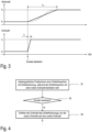
- the diagrams from Fig.3 illustrate an example in which the controller 4 reacts to contact detection not only by increasing the speed of the grinding wheel 11, but also with a controlled increase in the actuator force (force exerted by the actuator on the surface) starting at an adjustable minimum force F 0 up to the desired contact force F K .
- the actuator force is increased within a defined period of time T R.
- the increase in the actuator force can be linear, but this does not necessarily have to be the case.
- the values shown in the first diagram of the Fig.3 The dashed line shows a non-linear (S-shaped) increase in the actuator force.
- the second diagram of the Fig.3 shows the increase of the speed from n 0 to n 1 , where the rise time Ti can be shorter than the time period T R .
- a grinding machine with grinding tools see Fig.1 , grinding machine 10, grinding tool 11
- a manipulator/robot by means of a manipulator/robot, while the grinding machine is operated at a first speed
- This positioning can involve moving the grinding machine along a predefined trajectory.
- it is detected whether the grinding tool contacts the surface (see Fig.4 , step S2). This can be done, for example, by controlling the deflection of the actuator (cf. Fig.1 , Actuator 20), which is used for force control, changes.
- the speed of the motor of the grinding machine and thus the speed of the grinding tool is increased starting from the first speed (see Fig.4 , step S2).
Landscapes
- Engineering & Computer Science (AREA)
- Mechanical Engineering (AREA)
- Robotics (AREA)
- Finish Polishing, Edge Sharpening, And Grinding By Specific Grinding Devices (AREA)
- Manipulator (AREA)
- Constituent Portions Of Griding Lathes, Driving, Sensing And Control (AREA)
Claims (12)
- Dispositif de rectification servant à l'usinage d'une surface, comprenant :une rectifieuse (10) couplée à un manipulateur (1) avec un moteur et un outil de rectification (11) entraîné par le moteur ;une commande (4) conçue pour :commander la rectifieuse (10) afin de régler la vitesse de l'outil de rectification (11),positionner la rectifieuse (10) au moyen du manipulateur (1) afin de mettre en contact la surface avec l'outil de rectification (11) pendant que la rectifieuse fonctionne à une première vitesse (n0),détecter le contact entre l'outil de rectification (11) et la surface, etaugmenter la vitesse de l'outil de rectification (11) de la première vitesse (n0) à une seconde vitesse (n1) en réponse à la détection d'un contact.
- Dispositif de rectification selon la revendication 1, comprenant en outre :un actionneur (20) pour régler une force de contact entre l'outil de rectification (11) et la surface,dans lequel la commande (4) est conçue pour détecter le contact entre l'outil de rectification (11) et la surface en fonction de la déviation de l'actionneur ou de son changement.
- Dispositif de rectification selon la revendication 2,
dans lequel la commande (4) est en outre conçue pour augmenter la force de contact entre l'outil de rectification (11) et la surface en réponse à la détection de contact. - Dispositif de rectification selon l'une des revendications 1 à 3,
dans lequel la commande (4) est en outre conçue pour détecter une perte de contact et pour réduire la vitesse de l'outil de rectification (11) en réponse à une perte de contact. - Dispositif de rectification selon l'une des revendications 1 à 4,
dans lequel la commande (4) est en outre conçue pour augmenter la vitesse de l'outil de rectification (11) selon une trajectoire définie et prédéterminée. - Dispositif de rectification selon l'une des revendications 1 à 5,
dans lequel le manipulateur (1) est un robot industriel. - Procédé de rectification de surface automatisé, comprenant :le positionnement assisté par robot d'une rectifieuse (10) avec un outil de rectification (11), de sorte que l'outil de rectification (11) entre en contact avec la surface pendant que la rectifieuse (10) fonctionne à une première vitesse (n0),la détection du contact entre l'outil de rectification (11) et la surface ;l'augmentation de la vitesse de l'outil de rectification (11) de la première vitesse (n0) à une seconde vitesse (n1) en réponse à la détection du contact.
- Procédé selon la revendication 7, comprenant en outre :la régulation de la force de contact au moyen d'un actionneur linéaire (20) disposé entre un manipulateur (1) et la rectifieuse (10),dans lequel le contact entre l'outil de rectification (11) et la surface est détecté en fonction de la déviation de l'actionneur linéaire (20) ou de son changement.
- Procédé selon la revendication 8,
dans lequel la force de contact entre l'outil de rectification (11) et la surface est augmentée en réponse à la détection d'un contact. - Procédé selon l'une quelconque des revendications 7 à 9, comprenant en outre :la détection d'une perte de contact, etla réduction de la vitesse de l'outil de rectification (11) en réponse à la détection d'une perte de contact.
- Procédé selon l'une des revendications 7 à 10,
dans lequel la vitesse de l'outil de rectification (11) est augmentée selon une trajectoire définie et prédéterminée. - Procédé selon l'une des revendications 7 à 11,
dans lequel le positionnement assisté par robot de la rectifieuse est réalisé à l'aide d'un robot industriel.
Applications Claiming Priority (2)
| Application Number | Priority Date | Filing Date | Title |
|---|---|---|---|
| DE102018106086.6A DE102018106086A1 (de) | 2018-03-15 | 2018-03-15 | Drehzahlsteuerung beim robotergestützten schleifen |
| PCT/EP2019/056300 WO2019175251A1 (fr) | 2018-03-15 | 2019-03-13 | Régulation de vitesse avec rectification assistée par robot |
Publications (3)
| Publication Number | Publication Date |
|---|---|
| EP3765239A1 EP3765239A1 (fr) | 2021-01-20 |
| EP3765239C0 EP3765239C0 (fr) | 2024-05-01 |
| EP3765239B1 true EP3765239B1 (fr) | 2024-05-01 |
Family
ID=65802086
Family Applications (1)
| Application Number | Title | Priority Date | Filing Date |
|---|---|---|---|
| EP19711320.2A Active EP3765239B1 (fr) | 2018-03-15 | 2019-03-13 | Régulation de vitesse avec rectification assistée par robot |
Country Status (7)
| Country | Link |
|---|---|
| US (1) | US20210078135A1 (fr) |
| EP (1) | EP3765239B1 (fr) |
| JP (1) | JP7340536B2 (fr) |
| KR (1) | KR102642762B1 (fr) |
| CN (1) | CN111655427B (fr) |
| DE (1) | DE102018106086A1 (fr) |
| WO (1) | WO2019175251A1 (fr) |
Families Citing this family (9)
| Publication number | Priority date | Publication date | Assignee | Title |
|---|---|---|---|---|
| CN110842688B (zh) * | 2019-12-20 | 2024-06-21 | 同高先进制造科技(太仓)有限公司 | 车顶焊缝自动打磨系统 |
| US12097617B2 (en) | 2020-02-28 | 2024-09-24 | Ati Industrial Automation, Inc. | Controlling contact force in a machine tool |
| US11938632B2 (en) * | 2020-07-31 | 2024-03-26 | GrayMatter Robotics Inc. | Method for autonomously detecting and repairing defects in a workpiece in surface finishing applications |
| JP7742735B2 (ja) * | 2021-08-03 | 2025-09-22 | 川崎重工業株式会社 | ロボットシステム、ロボットの加工方法及び加工プログラム |
| KR102618657B1 (ko) | 2021-09-07 | 2023-12-29 | 한국생산기술연구원 | 로봇을 이용한 폴리싱 장치 및 이에 의한 폴리싱 방법 |
| KR102424699B1 (ko) | 2021-11-19 | 2022-07-22 | 곽동성 | 지그받침대의 선택 이동이 가능한 구조를 갖는 로봇 자동연마 가공을 위한 피연마물 공급장치 및 그 공급방법 |
| US12397421B2 (en) | 2021-12-22 | 2025-08-26 | Ati Industrial Automation, Inc. | Contact force overshoot mitigation in pneumatic force control devices |
| US11883961B2 (en) * | 2022-05-27 | 2024-01-30 | GrayMatter Robotics Inc. | Method for autonomously dimensional accuracy of a workpiece via three-dimensional sanding |
| KR102913378B1 (ko) | 2023-12-28 | 2026-01-16 | (주)정산 | 선박용 프로펠라 자동연마장치 |
Family Cites Families (16)
| Publication number | Priority date | Publication date | Assignee | Title |
|---|---|---|---|---|
| US5231803A (en) * | 1992-04-13 | 1993-08-03 | Minnesota Mining And Manufacturing Company | Automated random orbital abrading method |
| GB9315843D0 (en) * | 1993-07-30 | 1993-09-15 | Litton Uk Ltd | Improved machine tool |
| JP2000271865A (ja) * | 1999-03-26 | 2000-10-03 | Bosch Automotive Systems Corp | 砥石ユニット |
| US20030196528A1 (en) * | 2002-04-19 | 2003-10-23 | Cooper Christopher W. | Compliant cutoff saw assembly |
| US7166014B2 (en) * | 2004-01-26 | 2007-01-23 | Tbw Industries Inc. | Chemical mechanical planarization process control utilizing in-situ conditioning process |
| DE102006049956A1 (de) * | 2006-10-19 | 2008-04-24 | Abb Ag | System und Verfahren zur automatisierten Ver- und/oder Bearbeitung von Werkstücken |
| WO2011043225A1 (fr) * | 2009-10-05 | 2011-04-14 | 本田技研工業株式会社 | Dispositif et procédé de mesure d'irrégularité de surface à dents, dispositif et procédé de façonnage d'outil de meulage, et procédé d'appariement de dents pour dispositif de meulage de roue dentée |
| DE102011006679B4 (de) * | 2011-03-16 | 2018-07-12 | Ferrobotics Compliant Robot Technology Gmbh | Aktive Handhabungsvorrichtung und Verfahren für Kontaktaufgaben |
| CN103302563B (zh) * | 2012-03-14 | 2015-11-25 | 富泰华工业(深圳)有限公司 | 打磨装置及使用该打磨装置的机械手 |
| US20130273818A1 (en) * | 2012-04-13 | 2013-10-17 | Hon Hai Precision Industry Co., Ltd. | Manipulator and polishing mechanism thereof |
| DE102014201436A1 (de) * | 2014-01-27 | 2015-07-30 | Robert Bosch Gmbh | Handwerkzeugmaschine |
| DE102014119532B4 (de) * | 2014-12-23 | 2016-11-03 | Ferrobotics Compliant Robot Technology Gmbh | Robotergestütztes Schleifverfahren und Vorrichtung zum robotergestützten Schleifen |
| DE102015104164B4 (de) * | 2015-03-19 | 2019-05-29 | Ferrobotics Compliant Robot Technology Gmbh | Verfahren und Vorrichtung zur robotergestützten Oberflächenbearbeitung |
| CN109311168B (zh) * | 2016-04-07 | 2022-12-13 | 菲尔罗伯蒂克斯顺从式机器人技术有限公司 | 机器人辅助的磨削装置 |
| KR101967509B1 (ko) * | 2016-07-27 | 2019-04-09 | 시오 컴퍼니 리미티드 | 가공 장치, 그 제어 방법 및 프로그램 |
| CN206123420U (zh) * | 2016-09-19 | 2017-04-26 | 深圳德菲实业有限公司 | 一种手机玻璃研磨机 |
-
2018
- 2018-03-15 DE DE102018106086.6A patent/DE102018106086A1/de not_active Withdrawn
-
2019
- 2019-03-13 US US16/980,958 patent/US20210078135A1/en active Pending
- 2019-03-13 JP JP2020548796A patent/JP7340536B2/ja active Active
- 2019-03-13 KR KR1020207020370A patent/KR102642762B1/ko active Active
- 2019-03-13 WO PCT/EP2019/056300 patent/WO2019175251A1/fr not_active Ceased
- 2019-03-13 EP EP19711320.2A patent/EP3765239B1/fr active Active
- 2019-03-13 CN CN201980009091.6A patent/CN111655427B/zh active Active
Also Published As
| Publication number | Publication date |
|---|---|
| WO2019175251A1 (fr) | 2019-09-19 |
| JP2021517520A (ja) | 2021-07-26 |
| CN111655427B (zh) | 2022-10-18 |
| CN111655427A (zh) | 2020-09-11 |
| EP3765239A1 (fr) | 2021-01-20 |
| US20210078135A1 (en) | 2021-03-18 |
| DE102018106086A1 (de) | 2019-09-19 |
| EP3765239C0 (fr) | 2024-05-01 |
| JP7340536B2 (ja) | 2023-09-07 |
| KR20200125928A (ko) | 2020-11-05 |
| KR102642762B1 (ko) | 2024-02-29 |
Similar Documents
| Publication | Publication Date | Title |
|---|---|---|
| EP3765239B1 (fr) | Régulation de vitesse avec rectification assistée par robot | |
| EP3439836B1 (fr) | Dispositif de ponçage robotisé | |
| DE102014119532B4 (de) | Robotergestütztes Schleifverfahren und Vorrichtung zum robotergestützten Schleifen | |
| EP3439825B1 (fr) | Poste de changement et procédé pour le changement automatique de moyens de meulage | |
| EP3325214B1 (fr) | Machine-outil assistée par un robot pour le traitement de surfaces | |
| EP3956102B1 (fr) | Dispositif servant au traitement de surfaces | |
| EP3481605B1 (fr) | Procédé et système de changement automatique d'arbres | |
| DE2442865C3 (de) | Vorrichtung, insbesondere Manipulator, zum raschen Bewegen und genauen Positionieren eines Laststellglieds längs eines vorgegebenen Weges | |
| DE102015104164B4 (de) | Verfahren und Vorrichtung zur robotergestützten Oberflächenbearbeitung | |
| EP4313506A1 (fr) | Appareil de manipulation commandé par force pour usinage de surface assisté par robot | |
| DE102006061752A1 (de) | Roboter und Verfahren zum Programmieren eines Roboters | |
| WO2020243762A2 (fr) | Compensation de tolérances de position pendant le traitement de surface robotisé | |
| EP3288712B1 (fr) | Dispositif servant à l'usinage de surface | |
| EP3999277B1 (fr) | Dispositif et procédé de retrait automatique de disques de meulage | |
| EP4330558B1 (fr) | Actionneur linéaire pneumatique | |
| EP3697567B1 (fr) | Aspiration destinée à un outil à meuler comprenant une meule à brosses radiales | |
| EP3934862B1 (fr) | Système de serrage rapide conçu pour relier des machines-outils à un robot | |
| EP3689554A1 (fr) | Ménagement d'une articulation de robot à l'aide d'une trajectoire modifiée | |
| AT17078U1 (de) | Handlingvorrichtung, Formgebungsmaschine, Anordnung daraus und Verfahren zum Betreiben | |
| EP4605172A1 (fr) | Poste de remplacement pour le remplacement automatique de moyens abrasifs |
Legal Events
| Date | Code | Title | Description |
|---|---|---|---|
| STAA | Information on the status of an ep patent application or granted ep patent |
Free format text: STATUS: UNKNOWN |
|
| STAA | Information on the status of an ep patent application or granted ep patent |
Free format text: STATUS: THE INTERNATIONAL PUBLICATION HAS BEEN MADE |
|
| PUAI | Public reference made under article 153(3) epc to a published international application that has entered the european phase |
Free format text: ORIGINAL CODE: 0009012 |
|
| STAA | Information on the status of an ep patent application or granted ep patent |
Free format text: STATUS: REQUEST FOR EXAMINATION WAS MADE |
|
| 17P | Request for examination filed |
Effective date: 20201013 |
|
| AK | Designated contracting states |
Kind code of ref document: A1 Designated state(s): AL AT BE BG CH CY CZ DE DK EE ES FI FR GB GR HR HU IE IS IT LI LT LU LV MC MK MT NL NO PL PT RO RS SE SI SK SM TR |
|
| AX | Request for extension of the european patent |
Extension state: BA ME |
|
| DAV | Request for validation of the european patent (deleted) | ||
| DAX | Request for extension of the european patent (deleted) | ||
| GRAP | Despatch of communication of intention to grant a patent |
Free format text: ORIGINAL CODE: EPIDOSNIGR1 |
|
| STAA | Information on the status of an ep patent application or granted ep patent |
Free format text: STATUS: GRANT OF PATENT IS INTENDED |
|
| INTG | Intention to grant announced |
Effective date: 20231127 |
|
| GRAS | Grant fee paid |
Free format text: ORIGINAL CODE: EPIDOSNIGR3 |
|
| GRAA | (expected) grant |
Free format text: ORIGINAL CODE: 0009210 |
|
| STAA | Information on the status of an ep patent application or granted ep patent |
Free format text: STATUS: THE PATENT HAS BEEN GRANTED |
|
| AK | Designated contracting states |
Kind code of ref document: B1 Designated state(s): AL AT BE BG CH CY CZ DE DK EE ES FI FR GB GR HR HU IE IS IT LI LT LU LV MC MK MT NL NO PL PT RO RS SE SI SK SM TR |
|
| REG | Reference to a national code |
Ref country code: GB Ref legal event code: FG4D Free format text: NOT ENGLISH |
|
| REG | Reference to a national code |
Ref country code: CH Ref legal event code: EP |
|
| REG | Reference to a national code |
Ref country code: IE Ref legal event code: FG4D Free format text: LANGUAGE OF EP DOCUMENT: GERMAN |
|
| REG | Reference to a national code |
Ref country code: DE Ref legal event code: R096 Ref document number: 502019011182 Country of ref document: DE |
|
| U01 | Request for unitary effect filed |
Effective date: 20240515 |
|
| U07 | Unitary effect registered |
Designated state(s): AT BE BG DE DK EE FI FR IT LT LU LV MT NL PT SE SI Effective date: 20240528 |
|
| PG25 | Lapsed in a contracting state [announced via postgrant information from national office to epo] |
Ref country code: IS Free format text: LAPSE BECAUSE OF FAILURE TO SUBMIT A TRANSLATION OF THE DESCRIPTION OR TO PAY THE FEE WITHIN THE PRESCRIBED TIME-LIMIT Effective date: 20240901 |
|
| PG25 | Lapsed in a contracting state [announced via postgrant information from national office to epo] |
Ref country code: HR Free format text: LAPSE BECAUSE OF FAILURE TO SUBMIT A TRANSLATION OF THE DESCRIPTION OR TO PAY THE FEE WITHIN THE PRESCRIBED TIME-LIMIT Effective date: 20240501 |
|
| PG25 | Lapsed in a contracting state [announced via postgrant information from national office to epo] |
Ref country code: GR Free format text: LAPSE BECAUSE OF FAILURE TO SUBMIT A TRANSLATION OF THE DESCRIPTION OR TO PAY THE FEE WITHIN THE PRESCRIBED TIME-LIMIT Effective date: 20240802 |
|
| PG25 | Lapsed in a contracting state [announced via postgrant information from national office to epo] |
Ref country code: ES Free format text: LAPSE BECAUSE OF FAILURE TO SUBMIT A TRANSLATION OF THE DESCRIPTION OR TO PAY THE FEE WITHIN THE PRESCRIBED TIME-LIMIT Effective date: 20240501 |
|
| PG25 | Lapsed in a contracting state [announced via postgrant information from national office to epo] |
Ref country code: PL Free format text: LAPSE BECAUSE OF FAILURE TO SUBMIT A TRANSLATION OF THE DESCRIPTION OR TO PAY THE FEE WITHIN THE PRESCRIBED TIME-LIMIT Effective date: 20240501 |
|
| PG25 | Lapsed in a contracting state [announced via postgrant information from national office to epo] |
Ref country code: PL Free format text: LAPSE BECAUSE OF FAILURE TO SUBMIT A TRANSLATION OF THE DESCRIPTION OR TO PAY THE FEE WITHIN THE PRESCRIBED TIME-LIMIT Effective date: 20240501 Ref country code: NO Free format text: LAPSE BECAUSE OF FAILURE TO SUBMIT A TRANSLATION OF THE DESCRIPTION OR TO PAY THE FEE WITHIN THE PRESCRIBED TIME-LIMIT Effective date: 20240801 Ref country code: IS Free format text: LAPSE BECAUSE OF FAILURE TO SUBMIT A TRANSLATION OF THE DESCRIPTION OR TO PAY THE FEE WITHIN THE PRESCRIBED TIME-LIMIT Effective date: 20240901 Ref country code: HR Free format text: LAPSE BECAUSE OF FAILURE TO SUBMIT A TRANSLATION OF THE DESCRIPTION OR TO PAY THE FEE WITHIN THE PRESCRIBED TIME-LIMIT Effective date: 20240501 Ref country code: GR Free format text: LAPSE BECAUSE OF FAILURE TO SUBMIT A TRANSLATION OF THE DESCRIPTION OR TO PAY THE FEE WITHIN THE PRESCRIBED TIME-LIMIT Effective date: 20240802 Ref country code: ES Free format text: LAPSE BECAUSE OF FAILURE TO SUBMIT A TRANSLATION OF THE DESCRIPTION OR TO PAY THE FEE WITHIN THE PRESCRIBED TIME-LIMIT Effective date: 20240501 Ref country code: RS Free format text: LAPSE BECAUSE OF FAILURE TO SUBMIT A TRANSLATION OF THE DESCRIPTION OR TO PAY THE FEE WITHIN THE PRESCRIBED TIME-LIMIT Effective date: 20240801 |
|
| PG25 | Lapsed in a contracting state [announced via postgrant information from national office to epo] |
Ref country code: CZ Free format text: LAPSE BECAUSE OF FAILURE TO SUBMIT A TRANSLATION OF THE DESCRIPTION OR TO PAY THE FEE WITHIN THE PRESCRIBED TIME-LIMIT Effective date: 20240501 |
|
| PG25 | Lapsed in a contracting state [announced via postgrant information from national office to epo] |
Ref country code: SK Free format text: LAPSE BECAUSE OF FAILURE TO SUBMIT A TRANSLATION OF THE DESCRIPTION OR TO PAY THE FEE WITHIN THE PRESCRIBED TIME-LIMIT Effective date: 20240501 Ref country code: RO Free format text: LAPSE BECAUSE OF FAILURE TO SUBMIT A TRANSLATION OF THE DESCRIPTION OR TO PAY THE FEE WITHIN THE PRESCRIBED TIME-LIMIT Effective date: 20240501 |
|
| PG25 | Lapsed in a contracting state [announced via postgrant information from national office to epo] |
Ref country code: SM Free format text: LAPSE BECAUSE OF FAILURE TO SUBMIT A TRANSLATION OF THE DESCRIPTION OR TO PAY THE FEE WITHIN THE PRESCRIBED TIME-LIMIT Effective date: 20240501 |
|
| PG25 | Lapsed in a contracting state [announced via postgrant information from national office to epo] |
Ref country code: SM Free format text: LAPSE BECAUSE OF FAILURE TO SUBMIT A TRANSLATION OF THE DESCRIPTION OR TO PAY THE FEE WITHIN THE PRESCRIBED TIME-LIMIT Effective date: 20240501 Ref country code: SK Free format text: LAPSE BECAUSE OF FAILURE TO SUBMIT A TRANSLATION OF THE DESCRIPTION OR TO PAY THE FEE WITHIN THE PRESCRIBED TIME-LIMIT Effective date: 20240501 Ref country code: RO Free format text: LAPSE BECAUSE OF FAILURE TO SUBMIT A TRANSLATION OF THE DESCRIPTION OR TO PAY THE FEE WITHIN THE PRESCRIBED TIME-LIMIT Effective date: 20240501 Ref country code: CZ Free format text: LAPSE BECAUSE OF FAILURE TO SUBMIT A TRANSLATION OF THE DESCRIPTION OR TO PAY THE FEE WITHIN THE PRESCRIBED TIME-LIMIT Effective date: 20240501 |
|
| REG | Reference to a national code |
Ref country code: DE Ref legal event code: R097 Ref document number: 502019011182 Country of ref document: DE |
|
| PLBE | No opposition filed within time limit |
Free format text: ORIGINAL CODE: 0009261 |
|
| STAA | Information on the status of an ep patent application or granted ep patent |
Free format text: STATUS: NO OPPOSITION FILED WITHIN TIME LIMIT |
|
| 26N | No opposition filed |
Effective date: 20250204 |
|
| U20 | Renewal fee for the european patent with unitary effect paid |
Year of fee payment: 7 Effective date: 20250304 |
|
| PG25 | Lapsed in a contracting state [announced via postgrant information from national office to epo] |
Ref country code: MC Free format text: LAPSE BECAUSE OF FAILURE TO SUBMIT A TRANSLATION OF THE DESCRIPTION OR TO PAY THE FEE WITHIN THE PRESCRIBED TIME-LIMIT Effective date: 20240501 |
|
| REG | Reference to a national code |
Ref country code: CH Ref legal event code: H13 Free format text: ST27 STATUS EVENT CODE: U-0-0-H10-H13 (AS PROVIDED BY THE NATIONAL OFFICE) Effective date: 20251023 |
|
| PG25 | Lapsed in a contracting state [announced via postgrant information from national office to epo] |
Ref country code: CH Free format text: LAPSE BECAUSE OF NON-PAYMENT OF DUE FEES Effective date: 20250331 |
|
| PG25 | Lapsed in a contracting state [announced via postgrant information from national office to epo] |
Ref country code: IE Free format text: LAPSE BECAUSE OF NON-PAYMENT OF DUE FEES Effective date: 20250313 |
|
| PGFP | Annual fee paid to national office [announced via postgrant information from national office to epo] |
Ref country code: GB Payment date: 20260324 Year of fee payment: 8 |
|
| U20 | Renewal fee for the european patent with unitary effect paid |
Year of fee payment: 8 Effective date: 20260317 |