EP3765274B1 - Procédé et système avec un dispositif pour chauffer un élément de connexion - Google Patents
Procédé et système avec un dispositif pour chauffer un élément de connexion Download PDFInfo
- Publication number
- EP3765274B1 EP3765274B1 EP19711299.8A EP19711299A EP3765274B1 EP 3765274 B1 EP3765274 B1 EP 3765274B1 EP 19711299 A EP19711299 A EP 19711299A EP 3765274 B1 EP3765274 B1 EP 3765274B1
- Authority
- EP
- European Patent Office
- Prior art keywords
- nozzle
- sleeve
- connecting element
- end side
- open end
- Prior art date
- Legal status (The legal status is an assumption and is not a legal conclusion. Google has not performed a legal analysis and makes no representation as to the accuracy of the status listed.)
- Active
Links
Images

Classifications
-
- B—PERFORMING OPERATIONS; TRANSPORTING
- B29—WORKING OF PLASTICS; WORKING OF SUBSTANCES IN A PLASTIC STATE IN GENERAL
- B29C—SHAPING OR JOINING OF PLASTICS; SHAPING OF MATERIAL IN A PLASTIC STATE, NOT OTHERWISE PROVIDED FOR; AFTER-TREATMENT OF THE SHAPED PRODUCTS, e.g. REPAIRING
- B29C65/00—Joining or sealing of preformed parts, e.g. welding of plastics materials; Apparatus therefor
- B29C65/02—Joining or sealing of preformed parts, e.g. welding of plastics materials; Apparatus therefor by heating, with or without pressure
- B29C65/10—Joining or sealing of preformed parts, e.g. welding of plastics materials; Apparatus therefor by heating, with or without pressure using hot gases (e.g. combustion gases) or flames coming in contact with at least one of the parts to be joined
-
- B—PERFORMING OPERATIONS; TRANSPORTING
- B29—WORKING OF PLASTICS; WORKING OF SUBSTANCES IN A PLASTIC STATE IN GENERAL
- B29C—SHAPING OR JOINING OF PLASTICS; SHAPING OF MATERIAL IN A PLASTIC STATE, NOT OTHERWISE PROVIDED FOR; AFTER-TREATMENT OF THE SHAPED PRODUCTS, e.g. REPAIRING
- B29C65/00—Joining or sealing of preformed parts, e.g. welding of plastics materials; Apparatus therefor
- B29C65/56—Joining or sealing of preformed parts, e.g. welding of plastics materials; Apparatus therefor using mechanical means or mechanical connections, e.g. form-fits
- B29C65/60—Riveting or staking
- B29C65/606—Riveting or staking the rivets being integral with one of the parts to be joined, i.e. staking
-
- B—PERFORMING OPERATIONS; TRANSPORTING
- B29—WORKING OF PLASTICS; WORKING OF SUBSTANCES IN A PLASTIC STATE IN GENERAL
- B29C—SHAPING OR JOINING OF PLASTICS; SHAPING OF MATERIAL IN A PLASTIC STATE, NOT OTHERWISE PROVIDED FOR; AFTER-TREATMENT OF THE SHAPED PRODUCTS, e.g. REPAIRING
- B29C66/00—General aspects of processes or apparatus for joining preformed parts
- B29C66/003—Protecting areas of the parts to be joined from overheating
-
- B—PERFORMING OPERATIONS; TRANSPORTING
- B29—WORKING OF PLASTICS; WORKING OF SUBSTANCES IN A PLASTIC STATE IN GENERAL
- B29C—SHAPING OR JOINING OF PLASTICS; SHAPING OF MATERIAL IN A PLASTIC STATE, NOT OTHERWISE PROVIDED FOR; AFTER-TREATMENT OF THE SHAPED PRODUCTS, e.g. REPAIRING
- B29C66/00—General aspects of processes or apparatus for joining preformed parts
- B29C66/01—General aspects dealing with the joint area or with the area to be joined
- B29C66/02—Preparation of the material, in the area to be joined, prior to joining or welding
- B29C66/024—Thermal pre-treatments
- B29C66/0242—Heating, or preheating, e.g. drying
-
- B—PERFORMING OPERATIONS; TRANSPORTING
- B29—WORKING OF PLASTICS; WORKING OF SUBSTANCES IN A PLASTIC STATE IN GENERAL
- B29C—SHAPING OR JOINING OF PLASTICS; SHAPING OF MATERIAL IN A PLASTIC STATE, NOT OTHERWISE PROVIDED FOR; AFTER-TREATMENT OF THE SHAPED PRODUCTS, e.g. REPAIRING
- B29C66/00—General aspects of processes or apparatus for joining preformed parts
- B29C66/01—General aspects dealing with the joint area or with the area to be joined
- B29C66/05—Particular design of joint configurations
- B29C66/10—Particular design of joint configurations particular design of the joint cross-sections
- B29C66/11—Joint cross-sections comprising a single joint-segment, i.e. one of the parts to be joined comprising a single joint-segment in the joint cross-section
- B29C66/112—Single lapped joints
- B29C66/1122—Single lap to lap joints, i.e. overlap joints
-
- B—PERFORMING OPERATIONS; TRANSPORTING
- B29—WORKING OF PLASTICS; WORKING OF SUBSTANCES IN A PLASTIC STATE IN GENERAL
- B29C—SHAPING OR JOINING OF PLASTICS; SHAPING OF MATERIAL IN A PLASTIC STATE, NOT OTHERWISE PROVIDED FOR; AFTER-TREATMENT OF THE SHAPED PRODUCTS, e.g. REPAIRING
- B29C66/00—General aspects of processes or apparatus for joining preformed parts
- B29C66/01—General aspects dealing with the joint area or with the area to be joined
- B29C66/05—Particular design of joint configurations
- B29C66/20—Particular design of joint configurations particular design of the joint lines, e.g. of the weld lines
- B29C66/21—Particular design of joint configurations particular design of the joint lines, e.g. of the weld lines said joint lines being formed by a single dot or dash or by several dots or dashes, i.e. spot joining or spot welding
-
- B—PERFORMING OPERATIONS; TRANSPORTING
- B29—WORKING OF PLASTICS; WORKING OF SUBSTANCES IN A PLASTIC STATE IN GENERAL
- B29C—SHAPING OR JOINING OF PLASTICS; SHAPING OF MATERIAL IN A PLASTIC STATE, NOT OTHERWISE PROVIDED FOR; AFTER-TREATMENT OF THE SHAPED PRODUCTS, e.g. REPAIRING
- B29C66/00—General aspects of processes or apparatus for joining preformed parts
- B29C66/40—General aspects of joining substantially flat articles, e.g. plates, sheets or web-like materials; Making flat seams in tubular or hollow articles; Joining single elements to substantially flat surfaces
- B29C66/41—Joining substantially flat articles ; Making flat seams in tubular or hollow articles
-
- B—PERFORMING OPERATIONS; TRANSPORTING
- B29—WORKING OF PLASTICS; WORKING OF SUBSTANCES IN A PLASTIC STATE IN GENERAL
- B29C—SHAPING OR JOINING OF PLASTICS; SHAPING OF MATERIAL IN A PLASTIC STATE, NOT OTHERWISE PROVIDED FOR; AFTER-TREATMENT OF THE SHAPED PRODUCTS, e.g. REPAIRING
- B29C66/00—General aspects of processes or apparatus for joining preformed parts
- B29C66/80—General aspects of machine operations or constructions and parts thereof
- B29C66/81—General aspects of the pressing elements, i.e. the elements applying pressure on the parts to be joined in the area to be joined, e.g. the welding jaws or clamps
- B29C66/816—General aspects of the pressing elements, i.e. the elements applying pressure on the parts to be joined in the area to be joined, e.g. the welding jaws or clamps characterised by the mounting of the pressing elements, e.g. of the welding jaws or clamps
- B29C66/8167—Quick change joining tools or surfaces
-
- B—PERFORMING OPERATIONS; TRANSPORTING
- B29—WORKING OF PLASTICS; WORKING OF SUBSTANCES IN A PLASTIC STATE IN GENERAL
- B29C—SHAPING OR JOINING OF PLASTICS; SHAPING OF MATERIAL IN A PLASTIC STATE, NOT OTHERWISE PROVIDED FOR; AFTER-TREATMENT OF THE SHAPED PRODUCTS, e.g. REPAIRING
- B29C66/00—General aspects of processes or apparatus for joining preformed parts
- B29C66/80—General aspects of machine operations or constructions and parts thereof
- B29C66/87—Auxiliary operations or devices
- B29C66/872—Starting or stopping procedures
-
- B—PERFORMING OPERATIONS; TRANSPORTING
- B29—WORKING OF PLASTICS; WORKING OF SUBSTANCES IN A PLASTIC STATE IN GENERAL
- B29C—SHAPING OR JOINING OF PLASTICS; SHAPING OF MATERIAL IN A PLASTIC STATE, NOT OTHERWISE PROVIDED FOR; AFTER-TREATMENT OF THE SHAPED PRODUCTS, e.g. REPAIRING
- B29C66/00—General aspects of processes or apparatus for joining preformed parts
- B29C66/90—Measuring or controlling the joining process
- B29C66/96—Measuring or controlling the joining process characterised by the method for implementing the controlling of the joining process
- B29C66/967—Measuring or controlling the joining process characterised by the method for implementing the controlling of the joining process involving special data inputs or special data outputs, e.g. for monitoring purposes
- B29C66/9672—Measuring or controlling the joining process characterised by the method for implementing the controlling of the joining process involving special data inputs or special data outputs, e.g. for monitoring purposes involving special data inputs, e.g. involving barcodes, RFID tags
-
- B—PERFORMING OPERATIONS; TRANSPORTING
- B29—WORKING OF PLASTICS; WORKING OF SUBSTANCES IN A PLASTIC STATE IN GENERAL
- B29C—SHAPING OR JOINING OF PLASTICS; SHAPING OF MATERIAL IN A PLASTIC STATE, NOT OTHERWISE PROVIDED FOR; AFTER-TREATMENT OF THE SHAPED PRODUCTS, e.g. REPAIRING
- B29C66/00—General aspects of processes or apparatus for joining preformed parts
- B29C66/01—General aspects dealing with the joint area or with the area to be joined
- B29C66/348—Avoiding melting or weakening of the zone directly next to the joint area, e.g. by cooling
-
- B—PERFORMING OPERATIONS; TRANSPORTING
- B29—WORKING OF PLASTICS; WORKING OF SUBSTANCES IN A PLASTIC STATE IN GENERAL
- B29C—SHAPING OR JOINING OF PLASTICS; SHAPING OF MATERIAL IN A PLASTIC STATE, NOT OTHERWISE PROVIDED FOR; AFTER-TREATMENT OF THE SHAPED PRODUCTS, e.g. REPAIRING
- B29C66/00—General aspects of processes or apparatus for joining preformed parts
- B29C66/80—General aspects of machine operations or constructions and parts thereof
- B29C66/83—General aspects of machine operations or constructions and parts thereof characterised by the movement of the joining or pressing tools
- B29C66/832—Reciprocating joining or pressing tools
- B29C66/8322—Joining or pressing tools reciprocating along one axis
Definitions
- the invention relates to a system according to the preamble of claim 1. Furthermore, the invention relates to a method for heating a connecting element according to the preamble of claim 9.
- a first part is brought into contact with a second part, or a joining partner, and then firmly connected to one another using a connecting element, or a rivet or a pin.
- Thermal riveting of plastic parts involves using a hot medium, such as hot air, to heat the plastic fastener and make it malleable so that a forming die can deform the fastener to join the two parts.
- a hot medium such as hot air
- DE 10 2016 006 097 A1 shows in Fig. 1 such a stamp 6 with an inner pressing part 7 and an outer mold part 8.
- a nozzle ( Fig. 2 ). This nozzle is, for example, designed like a tube and dimensioned in such a way that one end region can be guided at least partially over the connecting element.
- the invention is based on the object of creating a system and a method in which the aforementioned disadvantages are eliminated.
- a system for solving this problem has the features of claim 1. Accordingly, it is provided that a preferably at least partially tubular sleeve is arranged around the nozzle and an at least almost ring-like channel is formed between an outer wall of the nozzle and an inner wall of the sleeve.
- the nozzle can in particular be arranged axially in the sleeve.
- the ring-like channel has at least largely the same distance between the outer wall of the nozzle and the inner wall of the sleeve. However, it can also be provided that the distance between the outer wall and the inner wall varies.
- a cross section of the nozzle and/or a cross section of the sleeve deviates from a circular shape, namely is rather oval or has any shape.
- the hot medium can be fed to the connecting element through the nozzle, with an end region of the nozzle at least partially enclosing the connecting element, and that the medium can be discharged from the nozzle through a gap between the end face of the nozzle and a surface of the second part and can be led away through the channel.
- this is done either actively or passively.
- a further development of the present invention can provide that an open end face of the nozzle forming an outlet and an open end face of the sleeve forming an inlet are arranged at a distance above a surface of the second part, with a gap being formed between the end faces and the surface of the second part.
- the distance of the end faces to the surface or the width of the gap can be 0.1 mm, 0.2 mm or 0.5 mm, 1.0 mm, 2.0 mm or 5.0 mm.
- the distance of the front sides to the surface or the gap width can vary depending on the amount of hot medium to be transported through the nozzle.
- an advantageous embodiment of the present invention can provide that an open end face of the nozzle, which forms an outlet, is arranged at a distance above a surface of the second part, whereby a gap is formed between the end face of the nozzle and the surface, and an open end face of the sleeve, which forms an inlet, is in contact with the surface of the second part, in particular in a closing manner, whereby an inner wall of the sleeve forms a closed chamber around the nozzle at least to the surface of the second part.
- the distance of the end face of the nozzle to the surface or the gap width can take on the same dimension as described in the previous paragraph.
- the hot medium is returned to the device or nozzle.
- the extracted air can be fed back into a heating device used to heat the medium. Due to the residual energy in the still warm medium, less energy is required to heat the medium again.
- the front side of the nozzle protrudes from the front side of the sleeve or that the front side of the sleeve protrudes beyond the front side of the nozzle. This makes it possible to apply hot air to the connecting element or to extract the hot air more efficient.
- the sleeve that leads the nozzle serves to form a channel or chamber that is closed at least to the surface of the second part. This closing contact of the sleeve with the surface of the second part allows the hot medium to be guided away from the second part very efficiently, which minimizes or prevents heating of the second part or other components.
- the nozzle and the sleeve can be moved axially relative to one another and/or that the nozzle is spring-loaded against the sleeve or the sleeve against the nozzle. Because the sleeve can be moved relative to the nozzle, for example, the nozzle can first be guided over the connecting element and then the sleeve can be moved axially in such a way that its front side comes into contact with the surface of the second part. In the event that the entire amount of heat cannot be dissipated through the channel, the sleeve could be at least slightly spaced from the surface to allow the hot air to escape.
- the spring-loaded mounting of the sleeve can compensate for any irregularities or unevenness on the surface of the second part when the front side of the sleeve is placed on this surface.
- the spring-loaded mounting of the sleeve or spring preloading of the sleeve means that a connection between the sleeve and the surface that is at least as flush as possible can be achieved despite any irregularities or unevenness. Any vibrations of the device or the second part can also be compensated by the spring-loaded mounting of the sleeve.
- the nozzle and the sleeve form a structural unit and that this unit can be exchanged for another unit with a nozzle and a sleeve that have an inner diameter corresponding to the size of the connecting element, depending on the size of the connecting element, wherein the unit preferably has a quick-change system.
- the unit or set or assembly consists of the nozzle and the sleeve and is assigned to the device.
- Such a quick-change system makes it possible to react to changing requirements or situations in a quick and flexible manner.
- the inner diameter of the nozzle should correspond to the dimensions of the connecting element, at least in the broadest sense. However, the inner diameter of the nozzle must always be selected so that there is sufficient space between the inner wall of the nozzle and the connecting element to discharge the hot air.
- the nozzle and/or the sleeve is assigned at least one sensor means for receiving an identification or label or a barcode of the first and/or second part, wherein the type and nature of the connecting element can preferably also be determined via the at least one sensor means and the nozzle can be calibrated according to the type and nature of the connecting element.
- the entire process of heating the connecting element can be documented and stored using this sensor means or by identifying the parts. This can be particularly advantageous for quality control.
- One embodiment can provide that both the temperature and the volume flow of the hot air are regulated by a control unit.
- a control unit can also be used to move both the sleeve and the nozzle to the surface of the second part and to move them away from it again.
- the control unit has an image recognition system in order to guide the nozzle specifically over the connecting element.
- the control unit can determine directly or indirectly via an identification number what material the connecting element is made of. The hot air supply is then adjusted depending on the material.
- the hot medium is discharged through a channel between a sleeve arranged axially around the nozzle and the nozzle. This discharge prevents the environment, in particular the second part or the joining partner, from being heated too much. On the other hand, energy can be saved by discharging the hot medium or the air, since the returned air can be used again to heat the connecting element.
- an open end face of the nozzle forming an outlet and an open end face of the sleeve forming an inlet are positioned at a distance above a surface of the second part, wherein a gap is formed between the end faces and the surface of the second part.
- a further preferred embodiment of the present invention provides that an open end face of the nozzle forming an outlet is positioned at a distance above a surface of the second part, wherein a gap is formed between the end face of the nozzle and the surface and an open end face of the sleeve forming an inlet is brought into contact with the surface of the second part, in particular in a closing manner, wherein the inner wall of the sleeve forms a closed chamber around the nozzle at least to the surface of the second part.
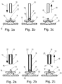
- first heat a connecting element 12 also referred to as pin or rivet
- a hot medium or hot air Fig. 1a, 1b, 1c
- the connecting element 12 is an integral part of the first part 10 and is guided through an opening in the second part 11.
- a nozzle 13 which is essentially tubular in design, is guided over the connecting element 12 in the direction of the arrow 14 ( Fig. 1a, 1b ).
- the connecting element 12 can also be fed to the nozzle.
- the hot air to be fed through the nozzle 13 is generated by a hot air generator (not shown). Air is first fed to the hot air generator and then heated to a predetermined temperature. The hot air is accelerated by a corresponding blower (not shown) and fed through the nozzle 13 directly to the connecting element 12.
- the nozzle 13 is guided over the connecting element 12 just far enough to form a gap 17 between the front side 15 and a surface 16 of the second part 11.
- the hot air flowing through the nozzle 13 thus heats the connecting element 12 and then leaves the nozzle 13 through the ring-like gap ( Fig. 1b ).
- the nozzle 13 is again guided away from the connecting element 12 in the direction of arrow 18 ( Fig. 1c ), or the connecting element 12 is guided away from the nozzle 13.
- the nozzle 13 is then moved in such a way that it can apply hot air to another connecting element 12, or another first part 10 is aligned together with the corresponding second part 11 relative to the nozzle 13 so that it can be guided over the connecting element 12.
- the disadvantage is that not only the connecting element 12 is heated, but also the surface 16 or the second part 11 or other sensitive components (not shown) that are in contact with the surface. Such heating can lead to irreversible damage.
- the Fig. 1a to 1c In the example shown, a large part of the thermal energy of the medium is lost unused.
- FIG. 2a to 2c The embodiment of the invention shown in the Fig. 1a to 1c
- the nozzle 13 shown is supplemented by a sleeve 19.
- Objects of the Fig. 2a to 2c which are identical to those of the Fig. 1a to 1c are given the same reference numbers for the sake of clarity.
- the nozzle 13 is guided over the connecting element 12 in such a way that a gap 17 remains between the surface 16 of the second part 11 and the end face 15 of the nozzle 13.
- the connecting element 12 it is equally conceivable for the connecting element 12 to be guided into the nozzle 13.
- the sleeve 19 is now arranged around the nozzle 13 in such a way that a channel 20 is formed between an outer wall of the nozzle 13 and an inner wall of the sleeve 19.
- This channel 20 can extend in a ring-like manner axially around the nozzle 13 or within the sleeve 19.
- this channel 20 has any shape and deviates from a ring-like shape.
- a front side 21 of the sleeve 19 is offset slightly backwards in the direction of the arrow 14. As a result, the front side 15 of the nozzle 13 and the front side 21 of the sleeve 19 are offset from one another. Thus, a distance between the front side 21 of the sleeve 19 and the surface 16 of the second part 11 is greater than a distance between the front side 15 of the nozzle 13 and the surface 16 of the second part 11 ( Fig. 2b ).
- the connecting element 12 is now subjected to hot air, the still hot air emerging from the front side 15 of the nozzle 13 can be sucked out through the channel 20 between the nozzle 13 and the sleeve 19.
- This suction can be carried out actively by a vacuum pump (not shown), which is connected to the sleeve 19 on a side opposite the front side 21, for example.
- the hot air is discharged passively through the channel 20 by the effect of the dynamic pressure. Through this active or passive discharge of the hot air, at least a large part of the hot air emerging from the nozzle 13 can be removed from the surface 16 and fed back to the hot air generator and the blower for reheating the connecting element 12.
- the unit consisting of sleeve 19 and nozzle 13 is moved away from the connecting element 12 in the direction of arrow 18 ( Fig. 2c ).
- FIG. 3a to 3c The embodiment of the invention shown in the drawings is significantly different from that shown in the Fig. 2a to 2c illustrated embodiment in that during the application of hot air to the connecting element 12 the front side 21 of the sleeve 19 is brought into contact with the surface 16 of the second part 11 ( Fig. 3b Otherwise, the situation is the same in the Fig. 3a to 3c
- the embodiment shown is similar to that shown in the Fig. 2a to 2c illustrated embodiment, which is why the same reference numerals are used for the same objects.
- the connecting element 12 can be heated without the surrounding parts, in particular the second part 11 or sensitive components, being exposed to excessive heat.
- the front side 21 of the sleeve 19 is arranged offset in the direction of arrow 14 to the front side 15 of the nozzle 13. Due to this offset, a gap 17 is formed between the front side 15 of the nozzle 13 and the surface 16, while the front side 21 of the sleeve 19 can be placed on the surface 16.
- the sleeve 19 and the nozzle 13 can be moved axially relative to each other. Due to the possibility of moving the nozzle 13 and the sleeve 19 relative to each other, both the embodiment of the Fig. 2a to 2c and the embodiment of the Fig. 3a to 3c can be realized. Due to a possible spring preload between the sleeve 19 and the nozzle 13, these move back to an initial position as soon as a force triggering the relative movement is switched off. Due to the spring preload or a spring-loaded mounting of the sleeve 19 or the nozzle 13, any irregularities or unevenness on the surface 16 of the second part 11 can be compensated for when the front side 21 of the sleeve 11 is placed on the surface 16.
- a connection between the sleeve 19 and the surface 16 that is at least largely flush can be achieved despite any irregularities or unevenness. Any vibrations of the device or the second part 11 can also be compensated for by the spring mounting of the sleeve 19.
- the relative movement can, for example, be carried out by a drive (not shown) that is operated by a control unit (also not shown) in such a way that when the unit consisting of the nozzle 13 and the sleeve 19 is lowered, the sleeve 19 is guided over the nozzle 13.
- This control unit can also be used to check whether the sleeve 19 or the nozzle 13 has been moved back to its original position after the connecting element 12 has been exposed to hot air.
Landscapes
- Engineering & Computer Science (AREA)
- Mechanical Engineering (AREA)
- Physics & Mathematics (AREA)
- Thermal Sciences (AREA)
- Chemical & Material Sciences (AREA)
- Combustion & Propulsion (AREA)
- Lining Or Joining Of Plastics Or The Like (AREA)
- Electric Connection Of Electric Components To Printed Circuits (AREA)
- Resistance Heating (AREA)
Claims (12)
- Système avec un dispositif pour chauffer un élément de liaison (12), notamment une broche ou un rivet, et avec une première partie (10) et avec une deuxième partie (11), le dispositif présentant une buse (13), et l'élément de liaison (12) pouvant être alimenté par la buse (13) avec un milieu chaud, de préférence de l'air chaud, et l'élément de liaison (12) étant associé à la première partie (10) et servant à la liaison de la première partie (10) avec la deuxième partie (11), notamment un partenaire d'assemblage, et un manchon (19) de type tubulaire étant agencé autour de la buse (13) et un canal (20) au moins presque annulaire étant réalisé entre une paroi extérieure de la buse (13) et une paroi intérieure du manchon (19), et le milieu chaud pouvant être amené à l'élément de liaison (12) par la buse (13), et le milieu pouvant être déchargé de la buse (13) par un espace (17) entre un côté frontal (15) de la buse (13) et une surface (16) de la deuxième partie (11) et pouvant être évacué par le canal (20), de préférence pouvant être aspiré activement ou passivement, caractérisé en ce qu'une zone d'extrémité de la buse (13) entoure au moins partiellement l'élément de liaison (12).
- Système selon la revendication 1, caractérisé en ce qu'un côté frontal ouvert (15) de la buse (13), formant une sortie, et un côté frontal ouvert (21) du manchon (19), formant une entrée, sont agencés à une distance au-dessus d'une surface (16) de la deuxième partie (11), un espace (17) se réalisant respectivement entre les côtés frontaux (15, 21) et la surface (16) de la deuxième partie (11).
- Système selon la revendication 1, caractérisé en ce qu'un côté frontal ouvert (15) de la buse (13) formant une sortie est agencé à distance au-dessus d'une surface (16) de la deuxième partie (11), un espace (17) se réalisant entre le côté frontal (15) de la buse (13) et la surface (16), et un côté frontal ouvert (21) du manchon (19) formant une entrée étant en contact, notamment de manière fermante, avec la surface (16) de la deuxième partie (11), une paroi intérieure du manchon (19) réalisant une chambre fermée autour de la buse (13) au moins vers la surface (16) de la deuxième partie (11).
- Système selon l'une quelconque des revendications précédentes, caractérisé en ce que le côté frontal (15) de la buse (13) dépasse du côté frontal (21) du manchon (19) ou en ce que le côté frontal (21) du manchon (19) dépasse du côté frontal (15) de la buse (13).
- Système selon l'une quelconque des revendications précédentes, caractérisé en ce que la buse (13) et le manchon (19) sont déplaçables axialement l'un par rapport à l'autre et/ou la buse (13) est montée à ressort contre le manchon (19).
- Système selon l'une quelconque des revendications précédentes, caractérisé en ce que la buse (13) et le manchon (19) forment une unité structurelle et cette unité peut être remplacée, en fonction d'une taille de l'élément de liaison (12), par une autre unité avec une buse (13) et un manchon (19) ayant des diamètres intérieurs correspondant à la taille de l'élément de liaison (12), l'unité présentant de préférence un système de changement rapide.
- Système selon l'une quelconque des revendications précédentes, caractérisé en ce qu'au moins un moyen de détection est associé à la buse (13) et/ou au manchon (19) pour recevoir une identification ou une inscription de la première et/ou de la deuxième partie (11), l'au moins un moyen de détection permettant de préférence de déterminer également le type et la nature de l'élément de liaison (12).
- Système selon l'une quelconque des revendications précédentes, caractérisé en ce que l'élément de liaison (12) chauffé est déformable par un poinçon de formage dans un autre dispositif pour le rivetage des parties (10, 11), le dispositif de chauffage étant séparé dans l'espace du dispositif de rivetage.
- Procédé de chauffage sans contact d'un élément de liaison (12), notamment d'une broche ou d'un rivet, par une buse (13) de type tubulaire, l'élément de liaison (12) étant alimenté avec un milieu chaud, de préférence de l'air chaud, et l'élément de liaison (12) étant associé à une première partie (10) et servant à la liaison de la première partie (10) à une deuxième partie (11), notamment un partenaire d'assemblage, et le milieu chaud étant amené à l'élément de liaison (12) par la buse (13), et le milieu étant déchargé de la buse (13) par un espace (17) entre un côté frontal (15) de la buse (13) et une surface (16) de la deuxième partie (11) et étant évacué par un canal (20) entre un manchon (19) agencé axialement autour de la buse (13) et la buse (13), de préférence étant aspiré activement ou passivement, caractérisé en ce que, pendant que le milieu chaud est amené à l'élément de liaison (12) par la buse (13), une zone d'extrémité de la buse (13) est agencée de manière à entourer au moins partiellement l'élément de liaison (12).
- Procédé selon la revendication 9, caractérisé en ce qu'un côté frontal ouvert (15) de la buse (13), formant une sortie, et un côté frontal ouvert (21) du manchon (19), formant une entrée, sont positionnés à une distance au-dessus d'une surface (16) de la deuxième partie (11), un espace se réalisant respectivement entre les côtés frontaux (15, 17) et la surface (16) de la deuxième partie (11).
- Procédé selon la revendication 9, caractérisé en ce qu' un côté frontal ouvert (15) de la buse (13) formant une sortie est positionné à distance au-dessus d'une surface (15) de la deuxième partie (11), un espace (17) se réalisant entre le côté frontal (15) de la buse (13) et la surface (16), et un côté frontal ouvert (21) du manchon (19) formant une entrée étant mise en contact, notamment de manière fermante, avec la surface (15) de la deuxième partie (11), la paroi intérieure du manchon (19) réalisant une chambre fermée autour de la buse (13) au moins vers la surface (15) de la deuxième partie (11).
- Procédé selon l'une quelconque des revendications 9 à 11, caractérisé en ce que l'élément de liaison (12) chauffé est déformé par un poinçon de formage dans un autre dispositif pour le rivetage des parties (10, 11), l'élément de liaison (12) étant transporté vers le dispositif de rivetage ou le dispositif de rivetage étant amené à l'élément de liaison (12).
Applications Claiming Priority (2)
| Application Number | Priority Date | Filing Date | Title |
|---|---|---|---|
| DE102018002084.4A DE102018002084A1 (de) | 2018-03-15 | 2018-03-15 | Verfahren und Vorrichtung zum Erhitzen eines Verbindungselementes |
| PCT/EP2019/056179 WO2019175187A1 (fr) | 2018-03-15 | 2019-03-12 | Procédé et dispositif servant à réchauffer un élément de liaison |
Publications (3)
| Publication Number | Publication Date |
|---|---|
| EP3765274A1 EP3765274A1 (fr) | 2021-01-20 |
| EP3765274B1 true EP3765274B1 (fr) | 2025-02-19 |
| EP3765274C0 EP3765274C0 (fr) | 2025-02-19 |
Family
ID=65802068
Family Applications (1)
| Application Number | Title | Priority Date | Filing Date |
|---|---|---|---|
| EP19711299.8A Active EP3765274B1 (fr) | 2018-03-15 | 2019-03-12 | Procédé et système avec un dispositif pour chauffer un élément de connexion |
Country Status (5)
| Country | Link |
|---|---|
| EP (1) | EP3765274B1 (fr) |
| CN (1) | CN111867814B (fr) |
| DE (1) | DE102018002084A1 (fr) |
| TW (1) | TWI809057B (fr) |
| WO (1) | WO2019175187A1 (fr) |
Families Citing this family (1)
| Publication number | Priority date | Publication date | Assignee | Title |
|---|---|---|---|---|
| DE102018204613B4 (de) | 2018-03-27 | 2023-10-05 | Robert Bosch Gmbh | Vorrichtung und Verfahren zum Heißvernieten |
Family Cites Families (8)
| Publication number | Priority date | Publication date | Assignee | Title |
|---|---|---|---|---|
| US7571753B2 (en) * | 2006-12-18 | 2009-08-11 | Leo Martinez | Heat welding nozzle for sealing flooring seams |
| SE532090C2 (sv) * | 2008-02-22 | 2009-10-20 | Norden Machinery Ab | Hetgasmunstycke anpassat för att värma en dubbeltub,tubfyllningsmaskin innefattande ett hetgasmunstycke samt en metod för att försluta en dubbeltub |
| DE102009037993B4 (de) * | 2009-08-20 | 2014-07-03 | bdtronic GmbH | Exzenterschneckenpumpe |
| US8956496B2 (en) * | 2011-06-14 | 2015-02-17 | 3M Innovative Properties Company | Apparatus and methods for impinging a fluid on a substrate |
| DE102013000018B4 (de) * | 2012-01-25 | 2020-08-06 | bdtronic GmbH | Verfahren und Vorrichtung zum Verbinden von Gegenständen sowie deren Verwendung |
| DE102013114570B4 (de) * | 2013-12-19 | 2019-05-02 | Kurtz Gmbh | Injektor zum Befüllen einer Form mit Kunststoffpartikeln |
| DE102014114379A1 (de) * | 2014-10-02 | 2016-04-07 | Sonotronic Nagel Gmbh | Nietvorrichtung und Verfahren zu seiner Anwendung |
| DE102016006097A1 (de) * | 2016-05-20 | 2017-11-23 | Wolf Produktionssysteme GmbH & Co. KG | Vorrichtung zur Erzeugung des Kopfes einer Kunststoffniet sowie Verfahren hierfür |
-
2018
- 2018-03-15 DE DE102018002084.4A patent/DE102018002084A1/de not_active Withdrawn
-
2019
- 2019-03-12 WO PCT/EP2019/056179 patent/WO2019175187A1/fr not_active Ceased
- 2019-03-12 EP EP19711299.8A patent/EP3765274B1/fr active Active
- 2019-03-12 CN CN201980019283.5A patent/CN111867814B/zh active Active
- 2019-03-15 TW TW108108932A patent/TWI809057B/zh active
Also Published As
| Publication number | Publication date |
|---|---|
| CN111867814A (zh) | 2020-10-30 |
| CN111867814B (zh) | 2022-12-06 |
| TWI809057B (zh) | 2023-07-21 |
| DE102018002084A1 (de) | 2019-09-19 |
| WO2019175187A1 (fr) | 2019-09-19 |
| TW201940312A (zh) | 2019-10-16 |
| EP3765274A1 (fr) | 2021-01-20 |
| EP3765274C0 (fr) | 2025-02-19 |
Similar Documents
| Publication | Publication Date | Title |
|---|---|---|
| EP1180405A2 (fr) | Methode et dispositif d'assemblage des pièces au moyen d'un element plastiquement déformable | |
| EP2586595B1 (fr) | Procédé de raccordement d'une pièce en matière synthétique à une autre pièce | |
| DE102017010550A1 (de) | Vorrichtung zum thermischen Verschweißen von Kunststoffteilen sowie Anordnung enthaltend eine solche Vorrichtung | |
| WO2013076205A1 (fr) | Ensemble buse pour dispositif applicateur de bande de chant, servant à la projection d'air chaud sur une bande de chant ou une pièce thermoactivable sans adhésif ou revêtue d'un adhésif thermocollant, et dispositif applicateur de bande de chant équipé d'un ensemble buse | |
| DE10021786B4 (de) | Etikett-Befestigungsvorrichtung | |
| DE102005039214A1 (de) | Verfahren zum Verbinden des Stoß von Dichtungsprofilen sowie Vorrichtung zu dessen Durchführung | |
| DE102016006097A1 (de) | Vorrichtung zur Erzeugung des Kopfes einer Kunststoffniet sowie Verfahren hierfür | |
| DE102016001401A1 (de) | Verfahren und Vorrichtung zum Herstellen von Verbindungsbereichen an Faser-Matrix-Verbund-Bauteilen | |
| CH678412A5 (fr) | ||
| DE102012021836B4 (de) | Heißstempelnietvorrichtung | |
| EP3371064B1 (fr) | Plateau d'un applicateur d'etiquettes et dispositif et procede d'etiquettage | |
| DE102004028310B4 (de) | Verfahren und Vorrichtung zum Herstellen des Abschlusses eines Lichtleitfaserbündels | |
| EP3186063A1 (fr) | Système de traitement ultérieur de préformes fabriquées par moulage par injection | |
| EP3765274A1 (fr) | Procédé et dispositif servant à réchauffer un élément de liaison | |
| EP4384345A1 (fr) | Unité outil d'assemblage, dispositif de préhension d'outil et procédé d'assemblage | |
| EP3765275B1 (fr) | Procédé et dispositif pour riveter des pièces | |
| DE10352821B4 (de) | Vorrichtung zum Heißluftnieten | |
| DE202007015873U1 (de) | Spritzgießdüse | |
| DE2406661A1 (de) | Heizplatte zum erhitzen der freien enden von aus kunststoff bestehenden rohrkoerpern | |
| AT527300A4 (de) | Vorrichtung zum verbinden eines bauelements mit einem substrat | |
| EP4052889A1 (fr) | Procédé de rivetage et dispositif de rivetage pour dômes de rivet en matière plastique | |
| DE102018204613B4 (de) | Vorrichtung und Verfahren zum Heißvernieten | |
| DE2805545C3 (de) | Verfahren und Vorrichtung zum Druckverschweißen mindestens eines Rohres mit einer Platte | |
| DE102014001835B4 (de) | Verfahren zur Herstellung einer Kraftschlussverbindung von zwei Bauteilen | |
| DE102011109812B4 (de) | Bearbeitungsvorrichtung zur Herstellung einer Bauteilverbindung |
Legal Events
| Date | Code | Title | Description |
|---|---|---|---|
| STAA | Information on the status of an ep patent application or granted ep patent |
Free format text: STATUS: UNKNOWN |
|
| STAA | Information on the status of an ep patent application or granted ep patent |
Free format text: STATUS: THE INTERNATIONAL PUBLICATION HAS BEEN MADE |
|
| PUAI | Public reference made under article 153(3) epc to a published international application that has entered the european phase |
Free format text: ORIGINAL CODE: 0009012 |
|
| STAA | Information on the status of an ep patent application or granted ep patent |
Free format text: STATUS: REQUEST FOR EXAMINATION WAS MADE |
|
| 17P | Request for examination filed |
Effective date: 20200901 |
|
| AK | Designated contracting states |
Kind code of ref document: A1 Designated state(s): AL AT BE BG CH CY CZ DE DK EE ES FI FR GB GR HR HU IE IS IT LI LT LU LV MC MK MT NL NO PL PT RO RS SE SI SK SM TR |
|
| AX | Request for extension of the european patent |
Extension state: BA ME |
|
| DAV | Request for validation of the european patent (deleted) | ||
| DAX | Request for extension of the european patent (deleted) | ||
| RIC1 | Information provided on ipc code assigned before grant |
Ipc: B29C 65/60 20060101ALI20230718BHEP Ipc: B29C 65/10 20060101AFI20230718BHEP |
|
| STAA | Information on the status of an ep patent application or granted ep patent |
Free format text: STATUS: EXAMINATION IS IN PROGRESS |
|
| 17Q | First examination report despatched |
Effective date: 20230919 |
|
| GRAP | Despatch of communication of intention to grant a patent |
Free format text: ORIGINAL CODE: EPIDOSNIGR1 |
|
| STAA | Information on the status of an ep patent application or granted ep patent |
Free format text: STATUS: GRANT OF PATENT IS INTENDED |
|
| INTG | Intention to grant announced |
Effective date: 20240920 |
|
| GRAS | Grant fee paid |
Free format text: ORIGINAL CODE: EPIDOSNIGR3 |
|
| GRAA | (expected) grant |
Free format text: ORIGINAL CODE: 0009210 |
|
| STAA | Information on the status of an ep patent application or granted ep patent |
Free format text: STATUS: THE PATENT HAS BEEN GRANTED |
|
| AK | Designated contracting states |
Kind code of ref document: B1 Designated state(s): AL AT BE BG CH CY CZ DE DK EE ES FI FR GB GR HR HU IE IS IT LI LT LU LV MC MK MT NL NO PL PT RO RS SE SI SK SM TR |
|
| REG | Reference to a national code |
Ref country code: GB Ref legal event code: FG4D Free format text: NOT ENGLISH |
|
| REG | Reference to a national code |
Ref country code: CH Ref legal event code: EP |
|
| REG | Reference to a national code |
Ref country code: IE Ref legal event code: FG4D Free format text: LANGUAGE OF EP DOCUMENT: GERMAN |
|
| REG | Reference to a national code |
Ref country code: DE Ref legal event code: R096 Ref document number: 502019012950 Country of ref document: DE |
|
| U01 | Request for unitary effect filed |
Effective date: 20250311 |
|
| U07 | Unitary effect registered |
Designated state(s): AT BE BG DE DK EE FI FR IT LT LU LV MT NL PT RO SE SI Effective date: 20250319 |
|
| U20 | Renewal fee for the european patent with unitary effect paid |
Year of fee payment: 7 Effective date: 20250331 |
|
| PG25 | Lapsed in a contracting state [announced via postgrant information from national office to epo] |
Ref country code: RS Free format text: LAPSE BECAUSE OF FAILURE TO SUBMIT A TRANSLATION OF THE DESCRIPTION OR TO PAY THE FEE WITHIN THE PRESCRIBED TIME-LIMIT Effective date: 20250519 |
|
| PG25 | Lapsed in a contracting state [announced via postgrant information from national office to epo] |
Ref country code: PL Free format text: LAPSE BECAUSE OF FAILURE TO SUBMIT A TRANSLATION OF THE DESCRIPTION OR TO PAY THE FEE WITHIN THE PRESCRIBED TIME-LIMIT Effective date: 20250219 |
|
| PG25 | Lapsed in a contracting state [announced via postgrant information from national office to epo] |
Ref country code: ES Free format text: LAPSE BECAUSE OF FAILURE TO SUBMIT A TRANSLATION OF THE DESCRIPTION OR TO PAY THE FEE WITHIN THE PRESCRIBED TIME-LIMIT Effective date: 20250219 |
|
| PG25 | Lapsed in a contracting state [announced via postgrant information from national office to epo] |
Ref country code: IS Free format text: LAPSE BECAUSE OF FAILURE TO SUBMIT A TRANSLATION OF THE DESCRIPTION OR TO PAY THE FEE WITHIN THE PRESCRIBED TIME-LIMIT Effective date: 20250619 Ref country code: NO Free format text: LAPSE BECAUSE OF FAILURE TO SUBMIT A TRANSLATION OF THE DESCRIPTION OR TO PAY THE FEE WITHIN THE PRESCRIBED TIME-LIMIT Effective date: 20250519 |
|
| PG25 | Lapsed in a contracting state [announced via postgrant information from national office to epo] |
Ref country code: HR Free format text: LAPSE BECAUSE OF FAILURE TO SUBMIT A TRANSLATION OF THE DESCRIPTION OR TO PAY THE FEE WITHIN THE PRESCRIBED TIME-LIMIT Effective date: 20250219 |
|
| PG25 | Lapsed in a contracting state [announced via postgrant information from national office to epo] |
Ref country code: GR Free format text: LAPSE BECAUSE OF FAILURE TO SUBMIT A TRANSLATION OF THE DESCRIPTION OR TO PAY THE FEE WITHIN THE PRESCRIBED TIME-LIMIT Effective date: 20250520 |
|
| PG25 | Lapsed in a contracting state [announced via postgrant information from national office to epo] |
Ref country code: SM Free format text: LAPSE BECAUSE OF FAILURE TO SUBMIT A TRANSLATION OF THE DESCRIPTION OR TO PAY THE FEE WITHIN THE PRESCRIBED TIME-LIMIT Effective date: 20250219 |
|
| PG25 | Lapsed in a contracting state [announced via postgrant information from national office to epo] |
Ref country code: CZ Free format text: LAPSE BECAUSE OF FAILURE TO SUBMIT A TRANSLATION OF THE DESCRIPTION OR TO PAY THE FEE WITHIN THE PRESCRIBED TIME-LIMIT Effective date: 20250219 |
|
| REG | Reference to a national code |
Ref country code: CH Ref legal event code: H13 Free format text: ST27 STATUS EVENT CODE: U-0-0-H10-H13 (AS PROVIDED BY THE NATIONAL OFFICE) Effective date: 20251023 |
|
| PG25 | Lapsed in a contracting state [announced via postgrant information from national office to epo] |
Ref country code: SK Free format text: LAPSE BECAUSE OF FAILURE TO SUBMIT A TRANSLATION OF THE DESCRIPTION OR TO PAY THE FEE WITHIN THE PRESCRIBED TIME-LIMIT Effective date: 20250219 |
|
| PG25 | Lapsed in a contracting state [announced via postgrant information from national office to epo] |
Ref country code: MC Free format text: LAPSE BECAUSE OF FAILURE TO SUBMIT A TRANSLATION OF THE DESCRIPTION OR TO PAY THE FEE WITHIN THE PRESCRIBED TIME-LIMIT Effective date: 20250219 |
|
| PLBE | No opposition filed within time limit |
Free format text: ORIGINAL CODE: 0009261 |
|
| STAA | Information on the status of an ep patent application or granted ep patent |
Free format text: STATUS: NO OPPOSITION FILED WITHIN TIME LIMIT |
|
| PG25 | Lapsed in a contracting state [announced via postgrant information from national office to epo] |
Ref country code: CH Free format text: LAPSE BECAUSE OF NON-PAYMENT OF DUE FEES Effective date: 20250331 |
|
| PG25 | Lapsed in a contracting state [announced via postgrant information from national office to epo] |
Ref country code: IE Free format text: LAPSE BECAUSE OF NON-PAYMENT OF DUE FEES Effective date: 20250312 |
|
| 26N | No opposition filed |
Effective date: 20251120 |
|
| GBPC | Gb: european patent ceased through non-payment of renewal fee |
Effective date: 20250519 |
|
| U20 | Renewal fee for the european patent with unitary effect paid |
Year of fee payment: 8 Effective date: 20260227 |
|
| PG25 | Lapsed in a contracting state [announced via postgrant information from national office to epo] |
Ref country code: GB Free format text: LAPSE BECAUSE OF NON-PAYMENT OF DUE FEES Effective date: 20250519 |