EP3765313B1 - Pneu clouté - Google Patents
Pneu clouté Download PDFInfo
- Publication number
- EP3765313B1 EP3765313B1 EP19705107.1A EP19705107A EP3765313B1 EP 3765313 B1 EP3765313 B1 EP 3765313B1 EP 19705107 A EP19705107 A EP 19705107A EP 3765313 B1 EP3765313 B1 EP 3765313B1
- Authority
- EP
- European Patent Office
- Prior art keywords
- tire
- spike
- spikes
- tread
- pins
- Prior art date
- Legal status (The legal status is an assumption and is not a legal conclusion. Google has not performed a legal analysis and makes no representation as to the accuracy of the status listed.)
- Active
Links
Images



Classifications
-
- B—PERFORMING OPERATIONS; TRANSPORTING
- B60—VEHICLES IN GENERAL
- B60C—VEHICLE TYRES; TYRE INFLATION; TYRE CHANGING; CONNECTING VALVES TO INFLATABLE ELASTIC BODIES IN GENERAL; DEVICES OR ARRANGEMENTS RELATED TO TYRES
- B60C11/00—Tyre tread bands; Tread patterns; Anti-skid inserts
- B60C11/14—Anti-skid inserts, e.g. vulcanised into the tread band
- B60C11/16—Anti-skid inserts, e.g. vulcanised into the tread band of plug form, e.g. made from metal, textile
- B60C11/1675—Anti-skid inserts, e.g. vulcanised into the tread band of plug form, e.g. made from metal, textile with special shape of the plug- tip
-
- B—PERFORMING OPERATIONS; TRANSPORTING
- B60—VEHICLES IN GENERAL
- B60C—VEHICLE TYRES; TYRE INFLATION; TYRE CHANGING; CONNECTING VALVES TO INFLATABLE ELASTIC BODIES IN GENERAL; DEVICES OR ARRANGEMENTS RELATED TO TYRES
- B60C11/00—Tyre tread bands; Tread patterns; Anti-skid inserts
- B60C11/03—Tread patterns
- B60C11/0304—Asymmetric patterns
-
- B—PERFORMING OPERATIONS; TRANSPORTING
- B60—VEHICLES IN GENERAL
- B60C—VEHICLE TYRES; TYRE INFLATION; TYRE CHANGING; CONNECTING VALVES TO INFLATABLE ELASTIC BODIES IN GENERAL; DEVICES OR ARRANGEMENTS RELATED TO TYRES
- B60C11/00—Tyre tread bands; Tread patterns; Anti-skid inserts
- B60C11/14—Anti-skid inserts, e.g. vulcanised into the tread band
- B60C11/16—Anti-skid inserts, e.g. vulcanised into the tread band of plug form, e.g. made from metal, textile
-
- B—PERFORMING OPERATIONS; TRANSPORTING
- B60—VEHICLES IN GENERAL
- B60C—VEHICLE TYRES; TYRE INFLATION; TYRE CHANGING; CONNECTING VALVES TO INFLATABLE ELASTIC BODIES IN GENERAL; DEVICES OR ARRANGEMENTS RELATED TO TYRES
- B60C11/00—Tyre tread bands; Tread patterns; Anti-skid inserts
- B60C11/14—Anti-skid inserts, e.g. vulcanised into the tread band
- B60C11/16—Anti-skid inserts, e.g. vulcanised into the tread band of plug form, e.g. made from metal, textile
- B60C11/1625—Arrangements thereof in the tread patterns, e.g. irregular
-
- B—PERFORMING OPERATIONS; TRANSPORTING
- B60—VEHICLES IN GENERAL
- B60C—VEHICLE TYRES; TYRE INFLATION; TYRE CHANGING; CONNECTING VALVES TO INFLATABLE ELASTIC BODIES IN GENERAL; DEVICES OR ARRANGEMENTS RELATED TO TYRES
- B60C11/00—Tyre tread bands; Tread patterns; Anti-skid inserts
- B60C11/14—Anti-skid inserts, e.g. vulcanised into the tread band
- B60C11/16—Anti-skid inserts, e.g. vulcanised into the tread band of plug form, e.g. made from metal, textile
- B60C11/1643—Anti-skid inserts, e.g. vulcanised into the tread band of plug form, e.g. made from metal, textile with special shape of the plug-body portion, i.e. not cylindrical
-
- B—PERFORMING OPERATIONS; TRANSPORTING
- B60—VEHICLES IN GENERAL
- B60C—VEHICLE TYRES; TYRE INFLATION; TYRE CHANGING; CONNECTING VALVES TO INFLATABLE ELASTIC BODIES IN GENERAL; DEVICES OR ARRANGEMENTS RELATED TO TYRES
- B60C11/00—Tyre tread bands; Tread patterns; Anti-skid inserts
- B60C11/14—Anti-skid inserts, e.g. vulcanised into the tread band
- B60C11/16—Anti-skid inserts, e.g. vulcanised into the tread band of plug form, e.g. made from metal, textile
- B60C11/1643—Anti-skid inserts, e.g. vulcanised into the tread band of plug form, e.g. made from metal, textile with special shape of the plug-body portion, i.e. not cylindrical
- B60C11/1656—Anti-skid inserts, e.g. vulcanised into the tread band of plug form, e.g. made from metal, textile with special shape of the plug-body portion, i.e. not cylindrical concave or convex, e.g. barrel-shaped
-
- D—TEXTILES; PAPER
- D06—TREATMENT OF TEXTILES OR THE LIKE; LAUNDERING; FLEXIBLE MATERIALS NOT OTHERWISE PROVIDED FOR
- D06N—WALL, FLOOR, OR LIKE COVERING MATERIALS, e.g. LINOLEUM, OILCLOTH, ARTIFICIAL LEATHER, ROOFING FELT, CONSISTING OF A FIBROUS WEB COATED WITH A LAYER OF MACROMOLECULAR MATERIAL; FLEXIBLE SHEET MATERIAL NOT OTHERWISE PROVIDED FOR
- D06N1/00—Linoleum, e.g. linoxyn, polymerised or oxidised resin
-
- D—TEXTILES; PAPER
- D06—TREATMENT OF TEXTILES OR THE LIKE; LAUNDERING; FLEXIBLE MATERIALS NOT OTHERWISE PROVIDED FOR
- D06N—WALL, FLOOR, OR LIKE COVERING MATERIALS, e.g. LINOLEUM, OILCLOTH, ARTIFICIAL LEATHER, ROOFING FELT, CONSISTING OF A FIBROUS WEB COATED WITH A LAYER OF MACROMOLECULAR MATERIAL; FLEXIBLE SHEET MATERIAL NOT OTHERWISE PROVIDED FOR
- D06N3/00—Artificial leather, oilcloth or other material obtained by covering fibrous webs with macromolecular material, e.g. resins, rubber or derivatives thereof
- D06N3/04—Artificial leather, oilcloth or other material obtained by covering fibrous webs with macromolecular material, e.g. resins, rubber or derivatives thereof with macromolecular compounds obtained by reactions only involving carbon-to-carbon unsaturated bonds
- D06N3/06—Artificial leather, oilcloth or other material obtained by covering fibrous webs with macromolecular material, e.g. resins, rubber or derivatives thereof with macromolecular compounds obtained by reactions only involving carbon-to-carbon unsaturated bonds with polyvinylchloride or its copolymerisation products
-
- D—TEXTILES; PAPER
- D06—TREATMENT OF TEXTILES OR THE LIKE; LAUNDERING; FLEXIBLE MATERIALS NOT OTHERWISE PROVIDED FOR
- D06N—WALL, FLOOR, OR LIKE COVERING MATERIALS, e.g. LINOLEUM, OILCLOTH, ARTIFICIAL LEATHER, ROOFING FELT, CONSISTING OF A FIBROUS WEB COATED WITH A LAYER OF MACROMOLECULAR MATERIAL; FLEXIBLE SHEET MATERIAL NOT OTHERWISE PROVIDED FOR
- D06N7/00—Flexible sheet materials not otherwise provided for, e.g. textile threads, filaments, yarns or tow, glued on macromolecular material
Definitions
- the invention relates to a tire with a profiled tread, with an outer tire sidewall oriented towards the outside of the vehicle when the tire is mounted and an inner tire sidewall oriented towards the vehicle side, the outer tire sidewalls adhering to an outer tread area of the tread and the inner tire sidewall to a transverse to the direction of rotation of the tire Tire directly or indirectly adjacent to the outer tread portion arranged inner tread portion of the tread adjacent, wherein in the tread of the tire spikes are embedded, of which a spike pin protrudes over the tread.
- a pneumatic vehicle tire with a profiled tread in which spikes are embedded is known.
- Each spike is formed from a spike foot, a spike body and a spike pin, which protrudes beyond the tread of the pneumatic vehicle tire.
- the stud foot and the stud body are embedded in the tire.
- the spikes are transverse or in Circumferential direction of the tread or viewed in the vertical direction to the tread of the pneumatic vehicle tire asymmetrically formed. Due to the asymmetrical design of the spikes, their bedding rigidity in the rubber matrix of the tire can be influenced depending on the direction. This ensures, for example, that the spikes incline more during traction than during braking, which improves grip on ice.
- the bedding rigidity transversely to the running direction can also be different from that in the running direction, as a result of which the lateral support can be improved in a targeted manner while the traction and braking force remain the same.
- the WO 2014/122570 A1 describes a tire with spikes.
- the spike pins are designed asymmetrically in plan view. They have a flat contour along their two long sides and a toothed contour opposite.
- the serrated contours of the spikes can be oriented in or against the rolling direction of the tire, which can optimize their engagement with an ice sheet when braking or accelerating.
- the tire's lateral stability is not improved by the serrated contour and the orientation of the studs.
- the one in the WO 2014/072853 described spikes are asymmetrical.
- Their spike bodies which are trapezoidal in cross section, each have a front and a back, which are aligned approximately parallel to the axis of rotation of the tire.
- the surfaces of the front sides are made larger than those of the back sides. Oscillating movements of the spikes, which can lead to a loss of the spikes, can be avoided in this way.
- a spike for a tire with a spike foot, a center part, a spike head and a spike pin is known.
- the middle part is tapered compared to the spike head and the spike foot.
- the spike foot, the middle part and the spike head have essentially triangular basic shapes in cross section.
- the spike pin is designed differently in different versions and has different cross-sections with straight and rounded areas when viewed from above.
- the spike foot, the central part, the spike head and the spike pin are designed in such a way that their focal points are at least partially are arranged offset to one another transversely to the longitudinal extension of the spike.
- the spikes are not rotationally symmetrical.
- the spike pins can be arranged on the tire in such a way that an edge of the spike pins that is as long and pronounced as possible forms their front edges.
- the front edges can be straight, convex or concave.
- the braking and traction behavior of the tire can be improved by this design of the spikes, but not its lateral stability.
- the DE 10 2014 205353 A1 describes spikes for vehicle tires and vehicle tires in whose tread such spikes are embedded.
- the spike pins can have the shape of an isosceles triangle, cut off at one corner, with a plane of symmetry.
- the plane of symmetry is preferably aligned in the transverse direction of the tread.
- the spike pins are arranged in the outer area of the tread facing away from the longitudinal axis of the vehicle in such a way that their wider sides are closer to the edge of the tread.
- first spikes are formed in two axially lateral extension sections of the tread profile and only second spikes are formed in an axially central extension section located between the lateral extension sections.
- An upstream gripping edge and a downstream gripping edge of the spike tip of the first spikes are arranged symmetrically to a plane of symmetry. Laterally, the spike tip of the first spike is closed off by two lateral gripping edge sections.
- the first spikes are arranged in the axially lateral extension section of the tread profile in such a way that their lateral gripping edge sections, which are longer measured in the circumferential direction of the tire, face the outer tire sidewall.
- the object of the invention is achieved by a tire according to claim 1.
- the centrifugal force and the resulting incline of a vehicle places a greater load on the wheel on the outside of the corner.
- the centrifugal forces that occur are absorbed by the treads of the tires and by the spikes digging into the ice or snow cover.
- the longer sides of the spikes facing the outer side of the tire result in improved lateral guidance for the tire on the outside of the curve, which is therefore subject to greater loads.
- Due to the high forces occurring on this tire a comparatively long edge of a spike is pressed deep into a layer of ice, for example. The centrifugal forces are then transferred from the long edge of the spike and thus over a comparatively large area to the ice.
- a tire thus has spike pins in its outer tread area, the extended edges of which are directed towards the outer tire sidewall, while the longer edges of the spike pins arranged in its inner tread area point towards the inner tire sidewall.
- spike pins point in the more heavily loaded tread area of the tire with their extended edges in the direction of the acting centrifugal forces and engage in a layer of snow or ice with the advantages mentioned.
- a suitable profile such a tire can advantageously be mounted on both sides of the vehicle.
- a further advantage results from the fact that only one type of spike is used, which keeps the production costs of the tire low.
- the lateral guidance can be improved simply by the fact that, in the case of the spikes arranged in the outer tread area, the extent of the outer sides of the spike pins facing the outer tire sidewall, measured in the circumferential direction of the tire, is greater than the extent of the inner sides of the spike pins, measured in the circumferential direction, facing the inner tire sidewall .
- the spike pins each have only one plane of symmetry.
- the plane of symmetry makes it possible to use the same spikes for opposite tires.
- the plane of symmetry preferably divides the outside and the inside of the spike pin.
- Possible variants of the invention provide that the planes of symmetry of the spike pins are aligned perpendicular to the direction of travel of the tire or that the planes of symmetry are aligned at an angle ⁇ between 30° and 90°, particularly preferably between 45° and 90°, to the direction of travel of the tire.
- the running direction indicates the direction of movement of the tread of the tire around its axis of rotation when driving forward. Alignment of the planes of symmetry perpendicular to the direction of travel results in a parallel alignment of the extended outer sides of the spike pins to the direction of travel of the tire, which results in optimized lateral guidance of the tyre.
- the outer sides of the spike pins can be arranged in such a way that during acceleration the power transmission from the tire and the spikes arranged on it to the ground is improved.
- an optimization of the grip of the tire in or against its running direction can be achieved in that the spike pins do not have any planes of symmetry.
- the side of a spike pin oriented in the running direction can thus be designed differently from the side oriented counter to the running direction.
- the intervention of the spike in snow or ice can be optimized for a braking process and for an acceleration process.
- the spike pins of the tires to be mounted on opposite sides of a vehicle are arranged as mirror images of one another.
- the tires can advantageously be mounted on both sides of the vehicle. If spike pins are used without a plane of symmetry, a directional tire is obtained by arranging the spikes with their spike pins.
- the adhesion properties of a tire can be optimally adapted to the respective requirements.
- the outer sides of the spike pins aligned parallel to the running direction of the tyre optimized lateral support is achieved. Arranging the outer sides at an angle in relation to the running direction of the tire can improve the grip of the tire when accelerating or braking.
- the extent of the spike pins arranged in the inner tread area, measured in the circumferential direction of the tire, of the outer sides of the spike pins facing the inner tire flank is greater than the extent of their inner sides, measured in the circumferential direction, facing the outer tread area.
- the grip properties of the tire can be further improved in that the tire is designed asymmetrically by different profiling of the inner and outer tread area. A high cornering stability is achieved by such a design of the profile. This can through the Training and alignment of the spikes can also be achieved for icy roads according to a tire according to the invention.
- the tire is configured symmetrically by a mutually mirror-inverted profiling of the inner and outer tread area.
- the spikes and their spike pins are preferably also designed symmetrically, so that the tire can be used on both sides of a vehicle. If asymmetric spike pins are used, a directional tire is obtained.
- a transition area provided with spikes is provided between the outer and inner tread area and that the shape and/or the orientation of the spike pins of the spikes arranged in the transition area depends on the shape and/or the orientation of the Spike pins of the spikes arranged in the outer and/or the inner tread area deviates.
- spikes with spike pins are arranged in the inner and outer tread area, which have outer sides that are extended towards the respective adjacent tire flanks in order to improve cornering stability.
- spike pins with several planes of symmetry for example spike pins with rectangular, round or oval cross sections, can be used in order to achieve optimized power transmission when braking and accelerating. Power transmission can be further improved by adapting the profile of the various areas of the tire tread.
- all spikes arranged in the outer tread area are configured and aligned the same and/or that all spikes arranged in the inner tread area are configured and aligned the same and/or that all spikes arranged in the transition area are configured and aligned the same .
- the effect of the spikes can thus be optimized in the different areas of the tire tread.
- the fact that the spikes and thus the spike pins are always aligned in the same way enables cost-effective production of the tire.
- FIG. 1 shows a portion of a tread 11 of a tire 10 with an asymmetrical profile.
- the tire 10 is rotatably mounted about an axis of rotation 13 with an in Figures 16 to 20 Vehicle 40 shown connected.
- Vehicle 40 shown connected.
- the tire 10 and the vehicle 40 can thus be moved along a backward movement 31 or a forward movement 32, both of which are identified by an arrow.
- a running direction 33 also marked by an arrow, corresponds to the movement of the tread 11 when the tire 10 rotates forward and thus a forward movement 32 of the vehicle 40.
- the selected assignment between running direction 33 and forward movement 32 corresponds to a view from above of the tire 10.
- the tread 11 merges laterally into an outer tire flank 14 and oppositely into an inner tire flank 15 .
- the inner tire sidewall 15 faces the vehicle 40 when the tire 10 is mounted, while the outer tire sidewall 15 faces away from the vehicle 40 .
- the tread 11 is divided into an outer tread area 17 and an inner tread area 18 .
- the tread areas 17, 18 are not necessarily bound to a profile 12 formed therein. An orientation of the tread areas 17, 18 on the profile 12 is advantageous.
- the outer tread area 17 borders on the outer tire sidewall 14
- the inner tread area 18 borders on the inner tire sidewall 15 .
- the tread areas 17 , 18 are arranged separately from one another along a parting plane running in the circumferential direction 30 .
- the outer and the inner tread area 17, 18 differ in the asymmetric tire 10 shown by their profile 12, which is shown by way of example and schematically by corresponding lines.
- Asymmetric tire 10 has a defined mounting direction on a rim with a predetermined outside and inside.
- spikes 20 are not shown, as in the Figures 3 to 21 are shown.
- the tread 11 of a tire 10 shows a portion of a tread 11 of a tire 10 with a symmetrical profile. They are the same identifiers as for 1 introduced used.
- the tread 12 of the tire 10 is symmetrical along a circumferential plane of symmetry.
- the surface of symmetry forms the center of the tire 10 and the tread 11.
- the tread 11 is divided into an outer tread area 17 and an inner tread area 18 to describe the invention. Between the inner and the outer tread area 17, 18 a transition area 19 is marked.
- the tread areas 17, 18 and the transition area 19 are based on the profile 12 of the tread 11.
- the subdivision can also be provided in any other way, or a subdivision that does not provide a transition area 19 can be selected.
- Symmetrical tires 10 can be mounted on either side of the vehicle, they have no predetermined direction of travel.
- spikes 20 are not shown, as in the Figures 3 to 21 are shown.
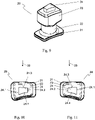
- FIG 3 shows a first spike 20 with a symmetrical spike pin 24 in a perspective view.
- the spike 20 has a flat spike foot 21 onto which a central part 22 is integrally formed.
- the middle part 22 is cylindrical. Opposite to the spike foot 21 closes Spike head 23 integrally connected to the middle part 22 at.
- a spike pin 24 is held in the spike head 23 .
- the spike head 23 has a receptacle into which the spike pin 24 is inserted.
- the spike pin 24 protrudes beyond the surface of the spike head 23 opposite the central part 22 .
- the spike foot 21, the central part 22 and the spike head 23 form a sleeve of the spike 20. They are made of a comparatively soft material, for example a metal, in particular steel or aluminum. It is also conceivable to produce the spike foot 21, the central part 22 and the spike head 23 from a plastic.
- the spike pin 24 is formed from a hard material.
- the spike pin 24 is preferably formed from hard metal, for example from tungsten carbide.
- the sleeve of the spike 20 is inserted into the receptacles provided for this purpose in the Figures 1 and 2 shown tread 11 of a tire 10 is used.
- the spike 20 anchors itself in the receptacle due to its shape.
- the spike 20 is inserted into the receptacle in such a way that only the spike pin 24 projects beyond the tread 11 of the tire 10 .
- the spike pin 24 penetrates a layer of snow or ice and thereby prevents the tire 10 from sliding.
- the spike pin 24 has a trapezoidal cross section. Its side surfaces form an outside 24.1 and an opposite inside 24.2.
- the outside 24.1 and the inside 24.2 are connected to one another by means of a third and a fourth side 24.3, 24.4.
- the trapezoidal shape results in a plane of symmetry 25 of the spike pin 24.
- the plane of symmetry 25 runs through the center of the outside 24.1 and the inside 24.2 of the spike pin 24.
- the third and the fourth side 24.3, 24.4 are arranged mirror-symmetrically to the plane of symmetry 25.
- the spike pin 24 has a single plane of symmetry 25 .
- the spike head 23 and the spike foot 21 of the spike 20 also have a trapezoidal cross section, which is aligned in accordance with the spike pin 24 in each case. This is advantageous to the spike pin 24 in its assembly in a desired orientation in the tread 11 of the tire 10 to anchor. However, it is also conceivable to design the spike foot 21 and/or the spike head 23 with a different cross section or with a different alignment compared to the spike pin 24 with a trapezoidal cross section.
- the outer side 24.1 of the spike pin 24 is longer, measured in the circumferential direction of the spike pin 24, than its inner side 24.2.
- the spike 20 is inserted into the tread 11 of the tire 10 in a directed manner.
- the outside 24.1 is oriented in the direction of a tire sidewall 14, 15 of the tire 10 and the inside 24.2 is oriented towards the opposite tire sidewall 14, 15.
- the extent of the outside 24.1 of the spike pin 24 is thus greater in the circumferential direction of the tire 10 than the extent of the inside 24.2.
- the running direction 33 of the tire 10 is indicated by an arrow in the selected representation. In the present case, the plane of symmetry 25 is aligned perpendicularly to the running direction 33 .
- the outside 24.1 and the inside 24.2 of the spike pin 24 are parallel to the running direction 33.
- the plane of symmetry 25 can also be aligned at an angle to the running direction 33.
- the outside 24.1 and the inside 24.2 are also arranged at an angle with respect to the running direction 33.
- figure 5 shows the in Figures 3 and 4 shown first spike 20 in a second orientation in plan view.
- the orientation of the spike 20 shown is, in relation to the running direction 33 of the tire 10, mirror-symmetrical to the in 4 orientation shown.
- the same spikes 20 can thus be used in a mirror-inverted manner in one tire 10 or in tires 10 mounted opposite.
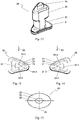
- FIG. 6 shows a second spike 20 with a symmetrical spike pin 24 in a perspective view.
- the second spike 20 also has a spike foot 21, a middle part 22 and a spike head 23 into which the spike pin 24 is inserted.
- the manufacture, assembly in a tire 10 and the function of the spike 20 according to the description of the Figures 3 to 5 , to which reference is hereby made.
- the spike pin 24 has a triangular cross section.
- the inside 24.2 of the spike pin 24 is formed by the apex of the triangle.
- the outside 24.1 of the spike pin 24 is arranged opposite the inside 24.2.
- the outside 24.1 forms the base of the triangle, while the third and the fourth side 24.3, 24.4 of the spike pin 24 represent the legs of the triangle.
- the plane of symmetry 25 of the spike pin 24 runs from the tip forming the inside 24.2 to the middle of the outside 24.1.
- the spike pin 24 thus has a plane of symmetry 25 . This makes it possible to arrange the same spikes 20, based on the running direction 33 of the tire 10, in a mirror-inverted manner in one or in opposite tires 10 mounted on a car, as is the case by the in FIGS Figures 7 and 8 illustrated orientations of the spike 20 is shown
- the spike foot 21 and the spike head 23 are also triangular, which enables the spike pin 24 to be easily aligned during the manufacture of the tire 10 .
- FIG. 9 shows a third spike 20 with an asymmetrical spike pin 24 in a perspective view.
- the spike 20 shown is, in relation to the running direction 33 of the tire 10, a mirror image of that in 11 Spike 20 shown formed and aligned.
- the basic structure and the function of the spikes 20 according to the representation of the Figures 3 to 9 . Deviating from the spikes 20 shown so far, the in the Figures 9 to 11 Spikepin 24 shown has no plane of symmetry 25.
- the extension of the outer side 24.1 of the spike pin 24 in the running direction 33 of the tire 10 is greater than the extension of its inner side measured in the same direction 24.1.
- the leading third side 24.3 of the spike pin 24 when driving forward runs transversely to the running direction 33. It is slightly convex.
- the opposite fourth side 24.3 of the spike pin 24 is oblique to the running direction 33 and concave.
- the contour of the spike foot 21 and the spike head 23 follows the contour of the spike pin 24. This facilitates the correct alignment of the spikes 20 within the tread 11 of the tire 10. However, it is also conceivable for the spike foot 21 and/or the Spike head 23 to provide a contour deviating from the cross section of the spike pin 24 .
- FIG. 12 shows a fourth spike 20 with an asymmetrical spike pin 24 in a perspective view.
- the in 13 The second alignment shown is mirror-symmetrical to that in 12 shown first alignment selected.
- the contour of the in 13 Spikes 20 or spike pins 24 shown are mirror images of the contour of the 14 spikes 20 or spike pins 24 shown.
- the spike pin 24 shown has no plane of symmetry 25 . It has an essentially triangular cross-section, with the leading third side 24.3 being convex and the trailing fourth side 24.4 being concave when driving forward. This shape improves the engagement of the spikes 20 when braking and accelerating.
- the inside 24.2 of the spike pin 24 is designed as a rounded edge.
- the outside 24.1 of the spike pin 24 is arranged opposite the inside 24.2. This extends in the running direction 33 of the tire 20.
- asymmetrical spike pin 24 are also in the in the Figures 12 to 14 shown, asymmetrical spike pin 24 for a mirror-symmetrical arrangement of spikes 20 on a tire 10 or on oppositely mounted tires 10 different, mirror-symmetrical to each other trained spikes 20 or spikes 20 with mirror images of each other trained spike pins 24 required.
- the contour of the spike foot 21 and the spike head 23 follows the contour of the spike pin 24. This facilitates the correct alignment of the spikes 20 within the tread 11 of the tire 10.
- the spike foot 21 and/or the spike head 23 to provide a contour deviating from the spike pin 24 .
- 15 shows a fifth spike 20 with an elliptical spike pin 24.
- the spike head 23 and the covered spike foot 21 are also elliptical.
- the spike 20 or the spike pin 24 thus has two planes of symmetry 25 .
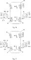
- 16 shows a schematic representation in a view from below
- 4-wheeled vehicle 40 in which the studded tires of a first arrangement are not in accordance with the present invention.
- the front wheels are turned for cornering, in the present case due to the representation from below for a right-hand bend.
- the spikes 20 set into the treads 11 of the tires 10 are shown schematically.
- the outer tire flanks 14 face away from the vehicle 40 while the inner tire walls 15 face the vehicle 40 .
- the running direction 33 of the rear and the turned front tires 10 is indicated by an arrow for forward travel in the contact area of the tires 10 on the ground.
- sections 41, 42 of the treads 11 of the tires 10 mounted there are shown enlarged.
- the cutouts 41, 42 show the shape and arrangement of the spikes 20 and their spike pins 24 in a plan view of the running surface 11.
- the spikes 20 set in the treads 11 of the tires 10 have spike pins 24 with a plane of symmetry 25, as shown in FIGS Figures 4, 5 , 7 and 8 are shown.
- the contour of the spike pin 24 corresponds to the contour of the Figures 3 to 5 shown spikes 20.
- the following description is for any other geometries of according to the illustration 16 arranged spike pins 24 with a plane of symmetry 25 applicable.
- the same spikes 20 with the same spike pins 24 are arranged over the entire tread 11 of a tire 10 in each case.
- the spike pins 24 are aligned within a tire 10 in the same way.
- the spikes 20, in particular the spike pins 24, are arranged mirror-symmetrically on the tires 10 mounted on the opposite sides of the vehicle 40.
- spikes 20 or spike pins 24 with an axis of symmetry 25 .
- the outer sides 24.1 of all spike pins 24 point to the respective outer tire flanks 14 and the inner sides 24.2 of the spike pins 24 correspond to the respective inner tire flank 15 of the tires 10 Figures 4 and 5
- the planes of symmetry 25 of the spike pins 24 shown are aligned transversely, in this case perpendicularly, to the running direction 33 of the tires 10 .
- the outside 24.1 and the inside 24.2 of the spike pin 24 are thus aligned in the running direction 33.
- the spike pins 24 shown are aligned transversely to the running direction 33 of the tires 10 . They bring about good adhesion of the tire 10 when braking and accelerating.
- the spike arrangement can be used for tires 10 with different profiles 12 .
- a tire 10 with a directional, symmetrical profile 12 as exemplified in 2 is shown, the spikes 20 or spike pins 24 arranged in a directed manner lead to a predetermined outer and inner side of the tire 10.
- An asymmetrical tire 10 is thus obtained by the arrangement and design of the spikes 20.
- the tire 10 must accordingly be mounted on a rim in such a way that the outer sides 24.1 of the spike pins 24 are directed away from the vehicle 40.
- the tire 10 can be used on both sides of the vehicle 40 .
- the in 16 Spike arrangement shown is provided on a tire 10 with an asymmetrical profile 12, as is the case, for example, in 1 is shown, the spikes 20 are to be inserted into the running surface 11 in such a way that the outer sides 24.1 of the spike pins 24 are directed in the direction of the direction specified by the profile 12 and mounted from the vehicle 40 pointing away from the outer tire sidewall 14 are aligned.
- the spikes in the arrangement shown can also be used for tires 10 that are directional due to their profile.
- FIG. 17 shows the in a schematic representation in a view from below 16 4, shown, is a four wheel vehicle 40 in which the studded tires of a second arrangement are not in accordance with the present invention.
- spikes 20 with spike pins 24 without a plane of symmetry 25 are inserted into the treads.
- the spikes 20 used correspond to those in FIGS Figures 9 to 12 shown spike 20, but the following description is also applicable to any other geometries of spike pins 24 without a plane of symmetry 25. So it is conceivable spikes 20 as shown in the Figures 12 to 14 to use.
- the spikes 20 and thus the spike pins 24 are aligned within a tire 10 in the same way, so that the longer outer sides 24.1 of the spike pins 24 point to the outer tire sidewall 14 and the opposite, shorter inner sides 24.2 of the spike pins to the inner tire side wall 15.
- the spikes 24 on tires 10 mounted opposite one another on the vehicle 40 are aligned mirror-symmetrically to one another. Since the spikes 20 or the spike pins 24 do not have a plane of symmetry, mirror-inverted spikes 20 or spike pins 24 are provided on the tires 10 mounted opposite on the vehicle 40 .
- the concave fourth side 24.4 of the spike pins 24 is therefore always aligned opposite to the direction of rotation of the tires 10.
- the third side 24.3 of the spike pins 24, which is approximately straight or slightly curved, is aligned in the direction of rotation of the tires 10.
- the spike arrangement shown with spike pins 24 without a plane of symmetry 25 can be used in tires 10 with different profiles 12 .
- the arrangement of the asymmetrical spikes 20 determines the running direction 33 of a tire 10 with a symmetrical profile 12 as well as a tire 10 with an asymmetrical profile 12 . This results in a directional, asymmetrical tire 10. If the spike arrangement is used on a tire 10 that is already directional due to its profile 12, it must be ensured that the running direction 33 specified by the profile 12 and the running direction 33 specified by the spikes 20 of the tires 10 match.
- the lengths of the inner sides 14.2 of the spike pins 24 measured in the running direction 33 of the tire 10 can be adapted to the expected load and thus to the requirements during driving. So the lengths of the inner sides 24.2 to sharp or rounded edges, like these in the Figures 6, 7, 8 and 12, 13, 14 are shown can be reduced, so that they penetrate well into a layer of ice even when the tire 10 is subjected to a low load when cornering.
- Spikes 20 are inserted into the treads 11 of the tires 10, the spike pins 24 of which have no plane of symmetry 25.
- the contour of the spikes 20 and the spike pins 24 corresponds to the contour in the Figures 9 to 11 shown Spikes 20 or spike pins 24, but any other spikes 20 with spike pins 24 without a plane of symmetry 25 can also be used.
- the tread 11 of the tires 10 is divided into an outer tread area 17 and an inner tread area 18, as shown in FIG 1 for an asymmetrically profiled tire 10 is shown.
- the outer tread area 17 is arranged towards the outside of the vehicle 40 and the inner tread area 18 is arranged towards the vehicle 40 .
- spikes 20 formed and aligned as mirror images of one another or spike pins 24 formed and aligned as mirror images of one another are arranged.
- the same spikes 20 or spike pins 24 are arranged in the same orientation.
- the spikes 20 of adjacent tread areas 17, 18 thus face each other with the shorter inner sides 24.2 of their spike pins 24 measured in the direction of rotation of the tire 10.
- the comparatively longer outer sides 24.1 of the spike pins 24 face the tire sidewall 14, 15 adjoining the respective tread area 17, 18.
- the outer sides 24 . 1 of the spike pins 24 arranged in the outer tread area 17 face the outer tire sidewall 14 and the outer sides 24 .
- the dividing line between the tread areas 17, 18 and thus the line of symmetry for the spike alignment preferably runs in the circumferential direction along the center plane of the tire 10. However, it can also be arranged shifted towards a tire sidewall 14, 15, so that tread areas 17, 18 of different widths result .
- the course of the parting line can be aligned with the profile 12 of the tread 11 of the tire 10 .
- a tire 10 with an asymmetrical profile 12 as is shown in 1 is shown to be arranged between two profile shapes of the tire 10 arranged next to one another in the running direction 33 .
- a tire 10 designed with such a spike arrangement has good lateral stability, in particular when cornering alternately.
- the outer tread portion 17 of the outside tire 10 is through the Tilt of the vehicle 40 and the deformation of the tire 10 most heavily loaded and pressed to the ground.
- the inner tread area 18 is subjected to a greater load than the outer tread area 17 facing away from the vehicle 40.
- the longer outer sides 24.1 of the spike pins 24 arranged in the inner tread area 18, which are aligned in the direction of the acting centrifugal force and thus towards the inner tire wall 15, grip well into a layer of snow or ice, and the comparatively short inner sides 24.2 of the spike pins 24 arranged in the less stressed outer tread area 17 of the tire 10 on the inside of the curve still penetrate so far into a layer of snow or ice that they provide lateral guidance for the tire 10 and thus of the vehicle 40 contribute.
- a tire 10 having a stud assembly as shown in FIG 18 has a predetermined running direction 33 due to the lack of a plane of symmetry 25 of the spike pins 24 .
- the running direction 33 of the shown shape of the spikepin 24 is specified in such a way that the convex-shaped fourth side 24.3 of the spikepin 24 leads when driving forward and the opposite, approximately straight or slightly outwardly curved third side 24.3 of the spikepin 24 leads the fourth side 24.4 lags behind accordingly.
- the grip properties of the tire 10 are optimized by the shape of the third and the fourth side 24.3, 24.4 of the spike pin 24 both for braking and for an acceleration process.
- such a spiked 20 tipped tire 10 can be mounted on both sides of the vehicle 40 if its profile 12 is designed symmetrically accordingly.
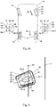
- spike pins 24 aligned mirror images of each other.
- the spike pins 24 have a plane of symmetry 25, as shown in FIGS Figures 4, 5 , 7 and 8 is shown.
- the shape of the spikes 20 selected in the illustration corresponds to that in FIGS Figures 3 to 5 Spike 20 shown.
- spikes 20 or spike pins 24 with a shape deviating from the contour shown, which have a plane of symmetry 25 described above.
- the spikes 20 are aligned in the tread 11 in such a way that their axes of symmetry 25 are aligned transversely to the direction of travel 33 of the tires 10 , in this case perpendicular to the direction of travel 33 of the tires 10 .
- the outer sides 24.1, which are extended in the circumferential direction of the tire 10, are aligned in the outer tread area 17 toward the outer tire flank 14.
- the spike pins 24 in the inner tread area 17, which are aligned as a mirror image, are aligned with their extended outer sides 24.1 towards the adjacent inner tire flank 15.
- the same spikes 20 are thus arranged in a mirror-symmetrical alignment in a tire 10 .
- the mirror plane is preferably arranged in the center of the tire. You can, as already 18 explained, also run outside the center of the tire oriented on the profile 12 of the tire 10 .
- the advantages of such a spike arrangement, based on the lateral guidance of a tire 10, correspond to the illustrations 18 .
- the tire 10 can be mounted on both sides of the vehicle 40.
- the tread 11 is divided into two tread areas 17, 18, in which different spikes 20 are arranged.
- spikes 20 that do not have a plane of symmetry 25 are arranged in the outer tread area 17 .
- spikes 20 with a plane of symmetry 25 in the outer tread area 17 are aligned with the extended outer sides 24.1 of their spike pins 24 toward the outer tire flank 14.
- the spike pins 24 of the spikes 20 arranged in the inner tread area 18 have two planes of symmetry 25 in the present case. They are oval in shape.
- spikes 20 with spike pins 24 in the inner running surface area 18, which spikes have more than two planes of symmetry 25 for example, spikes 20 can be provided, the spike pins 24 of which have a circular cross section.
- the parting plane running in the circumferential direction 30 of the tire 10 between the outer and the inner tread area 17, 18 can be selected as desired. You can orientate yourself on the profile 12 of the running surface 11 . For example, it can be arranged between two differently profiled areas of the running surface 11 .
- the spikes 20 arranged in the inner tread area 17 have little or no directional effect and thus bring about an approximately equal improvement in the grip of the tire 10 on slippery surfaces in all directions.
- the spike pin 24 of the Spikes 20 has a plane of symmetry 25 . This is inclined by an angle ⁇ 34 relative to the running direction 33 of the tire.
- the outside 24.1 of the spike pin 24 is thus also aligned at an angle ⁇ 35 obliquely to the running direction 33.
- the outer sides 24.1 of the spike pin 24, which are longer than the inner side 24.2, are thus aligned both towards the outer tire sidewall 14 and in the running direction 33 of the tire 10. With this arrangement, the extended outer sides 24.1 lead to improved adhesion of the tire 10 when cornering and when accelerating.
- the angle ⁇ 34 of the plane of symmetry 25 relative to the running direction 33 of the tire 10 is preferably in a range of 35° to 90°.
- the adhesion properties of a tire 10 can be optimized for improved cornering or for improved power transmission during an acceleration process.
- the orientation of the spikes 20 and the spike pins 24 retained therein is a mirror image on tires 10 mounted opposite one another on a vehicle 40 .
- the adhesion properties of the tires 10 can be optimized for different requirements by a suitable combination of tires 10 with specific profiles 12 and spike arrangements according to the invention. It is thus conceivable to provide tires 10 with an asymmetrically profiled tread 11, with the outer surface oriented towards the outside of the vehicle when the tire 10 is mounted Tread area 17 has a first profile 12 and the inner tread area 18 oriented towards the inside of the vehicle has a second profile 12 and spikes 20 are embedded in the tread 11 of the tire 10, from each of which a spike pin 24 protrudes over the tread 11.
- the longitudinal extension of the spike pin 24 runs from its end facing the tire 10 and enclosed in the spike sleeve to its outer end facing away from the tire 10 .
- tires 10 with a symmetrically profiled tread 11, with the profile 12 of the tread 11 being divided into an outer tread area 17 and an inner tread area 18 by a surface of symmetry running in the circumferential direction of the tire 10, and with the tread 11 of the Tire 10 spikes 20 are embedded, of which a spike pin 24 protrudes over the tread 11.
- spike arrangements can be provided as previously described.
- Spikes 20 with spike pins 24 can be arranged in the transition area 19, which differ in their shape and/or their orientation from the spike pins 24 of the spikes 20 arranged in the tread areas 17, 18 differ.
- spikes 20 with spike pins 24 can be arranged in the transition area, which spikes have two or more planes of symmetry 25 .
Landscapes
- Engineering & Computer Science (AREA)
- Mechanical Engineering (AREA)
- Textile Engineering (AREA)
- Chemical & Material Sciences (AREA)
- Chemical Kinetics & Catalysis (AREA)
- Tires In General (AREA)
Claims (9)
- Pneu (10) avec une bande de roulement profilée (11), avec un flanc de pneu extérieur (14) orienté vers le côté extérieur du véhicule lorsque le pneu (10) est monté et un flanc de pneu intérieur (15) orienté vers le côté du véhicule, le flanc extérieur (14) du pneu étant adjacent à une zone extérieure (17) de la bande de roulement (11) et le flanc de pneu intérieur (15) étant adjacent à une zone intérieure (18) de la bande de roulement (11) disposée directement ou indirectement à côté de la zone extérieure (17) de la bande de roulement, transversalement au sens de rotation du pneu (10), dans lequel des clous (20) sont noyés dans la zone extérieure (17) et dans la zone intérieure (18) de la bande de roulement (11) du pneu (10), dont une broche à clous (24) dépasse respectivement de la bande de roulement (11), dans lequel, pour les clous (20) disposés dans la zone extérieure (17) de la bande de roulement, l'étendue, mesurée dans la direction circonférentielle (30) du pneu (10), des côtés extérieurs (24.1) des broches à clous (24), tournés vers le flanc de pneu extérieur (14), est supérieure à l'étendue, mesurée dans la direction circonférentielle (30), des côtés intérieurs (24.2) des broches à clous (24), tournés vers le flanc de pneu intérieur (15),
caractérisé
en ce que les broches à clous (24) disposées dans la zone intérieure (18) de la bande de roulement sont réalisées et/ou orientées de manière miroir par rapport aux broches à clous (20) disposées dans la zone extérieure (17) de la bande de roulement. - Pneu (10) selon la revendication 1, caractérisé en ce que les broches à clous (24) présentent chacune un seul plan de symétrie (25).
- Pneu (10) selon la revendication 2, caractérisé en ce que les plans de symétrie (25) des broches à clous (24) sont orientés perpendiculairement à la direction de roulement (33) du pneu (10) ou en ce que les plans de symétrie (25) sont orientés selon un angle α (34) compris entre 30° et 90°, plus préférentiellement entre 45° et 90°, par rapport à la direction de roulement (33) du pneu (10).
- Pneu (10) selon la revendication 1, caractérisé en ce que les broches à clous (24) ne présentent pas de plans de symétrie (25).
- Pneu (10) selon l'une des revendications 1 à 4, caractérisé en ce que les côtés extérieurs (24.1) des épingles (24) tournés vers le flanc de pneu extérieur (14) sont orientés parallèlement à la direction de roulement (33) du pneu (10) ou en ce que les côtés extérieurs (24. 1) des broches à clous (24) sont orientées selon un angle β (35) par rapport à la direction de roulement (33) du pneu (10), de préférence que les côtés extérieurs (24.1) des broches à clous (24) tournés vers le flanc de pneu extérieur (14) sont orientés selon un angle β (35) compris entre 0 et 60°, de manière particulièrement préférée entre 0° et 45°, par rapport à la direction de roulement (33) du pneu (10).
- Pneu (10) selon l'une des revendications 1 à 5, caractérisé en ce que le pneu (10) est asymétrique par un profilage différent de la zone intérieure et de la zone extérieure (17, 18) de la bande de roulement.
- Pneu (10) selon l'une quelconque des revendications 1 à 6, caractérisé en ce que le pneu (10) est réalisé de manière symétrique par un profilage de la zone intérieure et de la zone extérieure (17, 18) de la bande de roulement réalisé de manière miroir l'une par rapport à l'autre.
- Pneu (10) selon l'une des revendications 1 à 7, caractérisé en ce qu'une zone de transition (19) pourvue de clous (24) est prévue entre la zone extérieure et la zone intérieure (17, 18) de la bande de roulement et en ce que la forme et/ou l'orientation des broches à clous (24) des clous (20) disposés dans la zone de transition (19) diffère de la forme et/ou de l'orientation des broches à clous (24) des clous (20) disposés dans la zone extérieure et/ou intérieure (17, 18) de la bande de roulement.
- Pneu (10) selon l'une quelconque des revendications 1 à 8, caractérisé en ce que tous les clous (20) disposés dans la zone extérieure (17) de la bande de roulement sont de forme et d'orientation identiques et/ou en ce que tous les clous (20) disposés dans la zone intérieure (18) de la bande de roulement sont de forme et d'orientation identiques et/ou en ce que tous les clous (20) disposés dans la zone de transition (19) sont de forme et d'orientation identiques.
Applications Claiming Priority (2)
| Application Number | Priority Date | Filing Date | Title |
|---|---|---|---|
| DE102018106021.1A DE102018106021A1 (de) | 2018-03-15 | 2018-03-15 | Spike-Reifen |
| PCT/EP2019/052289 WO2019174810A1 (fr) | 2018-03-15 | 2019-01-30 | Pneu clouté |
Publications (2)
| Publication Number | Publication Date |
|---|---|
| EP3765313A1 EP3765313A1 (fr) | 2021-01-20 |
| EP3765313B1 true EP3765313B1 (fr) | 2022-03-30 |
Family
ID=65411838
Family Applications (1)
| Application Number | Title | Priority Date | Filing Date |
|---|---|---|---|
| EP19705107.1A Active EP3765313B1 (fr) | 2018-03-15 | 2019-01-30 | Pneu clouté |
Country Status (4)
| Country | Link |
|---|---|
| EP (1) | EP3765313B1 (fr) |
| DE (2) | DE202018006249U1 (fr) |
| RU (1) | RU2747823C1 (fr) |
| WO (1) | WO2019174810A1 (fr) |
Family Cites Families (9)
| Publication number | Priority date | Publication date | Assignee | Title |
|---|---|---|---|---|
| ATE381448T1 (de) * | 2000-10-18 | 2008-01-15 | Continental Ag | Spike für fahrzeugreifen |
| US20130000807A1 (en) | 2011-06-28 | 2013-01-03 | Frederic Michel-Jean Pons | Anti-skid stud for insertion into the tread of a vehicle tire and pneumatic tire comprising such anti-skid studs |
| EP3549795B1 (fr) | 2012-11-12 | 2020-12-02 | Pirelli Tyre S.p.A. | Procédé pour améliorer la performance d'un pneumatique clouté et pneumatique clouté fabriqué selon ce procédé |
| CN104955662B (zh) | 2013-02-06 | 2017-08-11 | 倍耐力轮胎股份公司 | 装防滑钉的轮胎以及改善装防滑钉的轮胎性能的方法 |
| DE102014205353A1 (de) * | 2014-03-21 | 2015-09-24 | Continental Reifen Deutschland Gmbh | Spike und Fahrzeugreifen mit einem solchen Spike |
| JP6515498B2 (ja) * | 2014-11-18 | 2019-05-22 | 横浜ゴム株式会社 | 空気入りタイヤ |
| JP6393163B2 (ja) * | 2014-11-21 | 2018-09-19 | 株式会社ブリヂストン | スタッド、及び、スタッダブルタイヤ |
| DE102015225224A1 (de) | 2015-12-15 | 2017-06-22 | Continental Reifen Deutschland Gmbh | Fahrzeugluftreifen |
| DE102016212280A1 (de) * | 2016-07-06 | 2018-01-11 | Continental Reifen Deutschland Gmbh | Fahrzeugreifen |
-
2018
- 2018-03-15 DE DE202018006249.9U patent/DE202018006249U1/de active Active
- 2018-03-15 DE DE102018106021.1A patent/DE102018106021A1/de not_active Withdrawn
-
2019
- 2019-01-30 WO PCT/EP2019/052289 patent/WO2019174810A1/fr not_active Ceased
- 2019-01-30 EP EP19705107.1A patent/EP3765313B1/fr active Active
- 2019-01-30 RU RU2020127078A patent/RU2747823C1/ru active
Also Published As
| Publication number | Publication date |
|---|---|
| EP3765313A1 (fr) | 2021-01-20 |
| DE102018106021A1 (de) | 2019-09-19 |
| WO2019174810A1 (fr) | 2019-09-19 |
| DE202018006249U1 (de) | 2019-10-04 |
| RU2747823C1 (ru) | 2021-05-14 |
Similar Documents
| Publication | Publication Date | Title |
|---|---|---|
| DE69611341T2 (de) | Kraftfahrzeug-Luftreifen mit einem Laufflächenprofil besonders geeignet zum Laufen auf schneebedeckten Strassenoberflächen | |
| DE2621905C2 (fr) | ||
| DE69927666T2 (de) | Reifen mit opferbrücken | |
| EP3256333B1 (fr) | Pneumatique de véhicule | |
| EP4225594B1 (fr) | Pneu de véhicule à canal circonférentiel | |
| DE69202606T2 (de) | Luftreifen. | |
| EP2864137B1 (fr) | Bande de roulement de pneumatique | |
| EP2560830A1 (fr) | Pneu de véhicule | |
| DE60010833T2 (de) | Laufflächenprofil | |
| EP2376297B1 (fr) | Bandage pneumatique pour véhicule | |
| EP4577416A1 (fr) | Pneu de véhicule | |
| EP3724009B1 (fr) | Pneumatique de véhicule équipée d'une bande de roulement pourvue de crampons | |
| EP3765313B1 (fr) | Pneu clouté | |
| EP2138329B1 (fr) | Bande de roulement pour pneumatique | |
| EP4392268A1 (fr) | Pneu de véhicule utilitaire | |
| EP3659827B1 (fr) | Pneumatiques de véhicule comportant un profil de bande de roulement à une contre-dépouille | |
| EP4368416B1 (fr) | Bandage pneumatique pour véhicules | |
| EP2138328B1 (fr) | Pneus de véhicule | |
| EP4347276B1 (fr) | Pneu pour véhicule | |
| EP4363244A1 (fr) | Pneumatique pour véhicule | |
| EP3219514B1 (fr) | Pneumatiques de véhicule | |
| DE102020205836A1 (de) | Fahrzeugluftreifen | |
| WO2020114672A1 (fr) | Profil de bande de roulement d'un pneu de véhicule | |
| EP4197816A1 (fr) | Bandage pneumatique pour véhicule | |
| DE102024210365A1 (de) | Fahrzeugluftreifen |
Legal Events
| Date | Code | Title | Description |
|---|---|---|---|
| STAA | Information on the status of an ep patent application or granted ep patent |
Free format text: STATUS: UNKNOWN |
|
| STAA | Information on the status of an ep patent application or granted ep patent |
Free format text: STATUS: THE INTERNATIONAL PUBLICATION HAS BEEN MADE |
|
| PUAI | Public reference made under article 153(3) epc to a published international application that has entered the european phase |
Free format text: ORIGINAL CODE: 0009012 |
|
| STAA | Information on the status of an ep patent application or granted ep patent |
Free format text: STATUS: REQUEST FOR EXAMINATION WAS MADE |
|
| 17P | Request for examination filed |
Effective date: 20201015 |
|
| AK | Designated contracting states |
Kind code of ref document: A1 Designated state(s): AL AT BE BG CH CY CZ DE DK EE ES FI FR GB GR HR HU IE IS IT LI LT LU LV MC MK MT NL NO PL PT RO RS SE SI SK SM TR |
|
| AX | Request for extension of the european patent |
Extension state: BA ME |
|
| DAV | Request for validation of the european patent (deleted) | ||
| DAX | Request for extension of the european patent (deleted) | ||
| GRAP | Despatch of communication of intention to grant a patent |
Free format text: ORIGINAL CODE: EPIDOSNIGR1 |
|
| STAA | Information on the status of an ep patent application or granted ep patent |
Free format text: STATUS: GRANT OF PATENT IS INTENDED |
|
| INTG | Intention to grant announced |
Effective date: 20211029 |
|
| GRAS | Grant fee paid |
Free format text: ORIGINAL CODE: EPIDOSNIGR3 |
|
| GRAA | (expected) grant |
Free format text: ORIGINAL CODE: 0009210 |
|
| STAA | Information on the status of an ep patent application or granted ep patent |
Free format text: STATUS: THE PATENT HAS BEEN GRANTED |
|
| AK | Designated contracting states |
Kind code of ref document: B1 Designated state(s): AL AT BE BG CH CY CZ DE DK EE ES FI FR GB GR HR HU IE IS IT LI LT LU LV MC MK MT NL NO PL PT RO RS SE SI SK SM TR |
|
| REG | Reference to a national code |
Ref country code: GB Ref legal event code: FG4D Free format text: NOT ENGLISH |
|
| REG | Reference to a national code |
Ref country code: CH Ref legal event code: EP |
|
| REG | Reference to a national code |
Ref country code: AT Ref legal event code: REF Ref document number: 1478848 Country of ref document: AT Kind code of ref document: T Effective date: 20220415 |
|
| REG | Reference to a national code |
Ref country code: DE Ref legal event code: R096 Ref document number: 502019003873 Country of ref document: DE |
|
| REG | Reference to a national code |
Ref country code: IE Ref legal event code: FG4D Free format text: LANGUAGE OF EP DOCUMENT: GERMAN |
|
| REG | Reference to a national code |
Ref country code: NO Ref legal event code: T2 Effective date: 20220330 |
|
| REG | Reference to a national code |
Ref country code: FI Ref legal event code: FGE |
|
| REG | Reference to a national code |
Ref country code: SE Ref legal event code: TRGR |
|
| REG | Reference to a national code |
Ref country code: LT Ref legal event code: MG9D |
|
| PG25 | Lapsed in a contracting state [announced via postgrant information from national office to epo] |
Ref country code: RS Free format text: LAPSE BECAUSE OF FAILURE TO SUBMIT A TRANSLATION OF THE DESCRIPTION OR TO PAY THE FEE WITHIN THE PRESCRIBED TIME-LIMIT Effective date: 20220330 Ref country code: LT Free format text: LAPSE BECAUSE OF FAILURE TO SUBMIT A TRANSLATION OF THE DESCRIPTION OR TO PAY THE FEE WITHIN THE PRESCRIBED TIME-LIMIT Effective date: 20220330 Ref country code: HR Free format text: LAPSE BECAUSE OF FAILURE TO SUBMIT A TRANSLATION OF THE DESCRIPTION OR TO PAY THE FEE WITHIN THE PRESCRIBED TIME-LIMIT Effective date: 20220330 Ref country code: BG Free format text: LAPSE BECAUSE OF FAILURE TO SUBMIT A TRANSLATION OF THE DESCRIPTION OR TO PAY THE FEE WITHIN THE PRESCRIBED TIME-LIMIT Effective date: 20220630 |
|
| REG | Reference to a national code |
Ref country code: NL Ref legal event code: MP Effective date: 20220330 |
|
| PG25 | Lapsed in a contracting state [announced via postgrant information from national office to epo] |
Ref country code: LV Free format text: LAPSE BECAUSE OF FAILURE TO SUBMIT A TRANSLATION OF THE DESCRIPTION OR TO PAY THE FEE WITHIN THE PRESCRIBED TIME-LIMIT Effective date: 20220330 Ref country code: GR Free format text: LAPSE BECAUSE OF FAILURE TO SUBMIT A TRANSLATION OF THE DESCRIPTION OR TO PAY THE FEE WITHIN THE PRESCRIBED TIME-LIMIT Effective date: 20220701 |
|
| PG25 | Lapsed in a contracting state [announced via postgrant information from national office to epo] |
Ref country code: NL Free format text: LAPSE BECAUSE OF FAILURE TO SUBMIT A TRANSLATION OF THE DESCRIPTION OR TO PAY THE FEE WITHIN THE PRESCRIBED TIME-LIMIT Effective date: 20220330 |
|
| PG25 | Lapsed in a contracting state [announced via postgrant information from national office to epo] |
Ref country code: SM Free format text: LAPSE BECAUSE OF FAILURE TO SUBMIT A TRANSLATION OF THE DESCRIPTION OR TO PAY THE FEE WITHIN THE PRESCRIBED TIME-LIMIT Effective date: 20220330 Ref country code: SK Free format text: LAPSE BECAUSE OF FAILURE TO SUBMIT A TRANSLATION OF THE DESCRIPTION OR TO PAY THE FEE WITHIN THE PRESCRIBED TIME-LIMIT Effective date: 20220330 Ref country code: RO Free format text: LAPSE BECAUSE OF FAILURE TO SUBMIT A TRANSLATION OF THE DESCRIPTION OR TO PAY THE FEE WITHIN THE PRESCRIBED TIME-LIMIT Effective date: 20220330 Ref country code: PT Free format text: LAPSE BECAUSE OF FAILURE TO SUBMIT A TRANSLATION OF THE DESCRIPTION OR TO PAY THE FEE WITHIN THE PRESCRIBED TIME-LIMIT Effective date: 20220801 Ref country code: ES Free format text: LAPSE BECAUSE OF FAILURE TO SUBMIT A TRANSLATION OF THE DESCRIPTION OR TO PAY THE FEE WITHIN THE PRESCRIBED TIME-LIMIT Effective date: 20220330 Ref country code: EE Free format text: LAPSE BECAUSE OF FAILURE TO SUBMIT A TRANSLATION OF THE DESCRIPTION OR TO PAY THE FEE WITHIN THE PRESCRIBED TIME-LIMIT Effective date: 20220330 Ref country code: CZ Free format text: LAPSE BECAUSE OF FAILURE TO SUBMIT A TRANSLATION OF THE DESCRIPTION OR TO PAY THE FEE WITHIN THE PRESCRIBED TIME-LIMIT Effective date: 20220330 |
|
| PG25 | Lapsed in a contracting state [announced via postgrant information from national office to epo] |
Ref country code: PL Free format text: LAPSE BECAUSE OF FAILURE TO SUBMIT A TRANSLATION OF THE DESCRIPTION OR TO PAY THE FEE WITHIN THE PRESCRIBED TIME-LIMIT Effective date: 20220330 Ref country code: IS Free format text: LAPSE BECAUSE OF FAILURE TO SUBMIT A TRANSLATION OF THE DESCRIPTION OR TO PAY THE FEE WITHIN THE PRESCRIBED TIME-LIMIT Effective date: 20220730 Ref country code: AL Free format text: LAPSE BECAUSE OF FAILURE TO SUBMIT A TRANSLATION OF THE DESCRIPTION OR TO PAY THE FEE WITHIN THE PRESCRIBED TIME-LIMIT Effective date: 20220330 |
|
| REG | Reference to a national code |
Ref country code: DE Ref legal event code: R097 Ref document number: 502019003873 Country of ref document: DE |
|
| PG25 | Lapsed in a contracting state [announced via postgrant information from national office to epo] |
Ref country code: DK Free format text: LAPSE BECAUSE OF FAILURE TO SUBMIT A TRANSLATION OF THE DESCRIPTION OR TO PAY THE FEE WITHIN THE PRESCRIBED TIME-LIMIT Effective date: 20220330 |
|
| PLBE | No opposition filed within time limit |
Free format text: ORIGINAL CODE: 0009261 |
|
| STAA | Information on the status of an ep patent application or granted ep patent |
Free format text: STATUS: NO OPPOSITION FILED WITHIN TIME LIMIT |
|
| 26N | No opposition filed |
Effective date: 20230103 |
|
| PG25 | Lapsed in a contracting state [announced via postgrant information from national office to epo] |
Ref country code: SI Free format text: LAPSE BECAUSE OF FAILURE TO SUBMIT A TRANSLATION OF THE DESCRIPTION OR TO PAY THE FEE WITHIN THE PRESCRIBED TIME-LIMIT Effective date: 20220330 |
|
| P01 | Opt-out of the competence of the unified patent court (upc) registered |
Effective date: 20230505 |
|
| PG25 | Lapsed in a contracting state [announced via postgrant information from national office to epo] |
Ref country code: IT Free format text: LAPSE BECAUSE OF FAILURE TO SUBMIT A TRANSLATION OF THE DESCRIPTION OR TO PAY THE FEE WITHIN THE PRESCRIBED TIME-LIMIT Effective date: 20220330 |
|
| REG | Reference to a national code |
Ref country code: DE Ref legal event code: R081 Ref document number: 502019003873 Country of ref document: DE Owner name: BETEK GMBH & CO. KG, DE Free format text: FORMER OWNER: SITEK-SPIKES GMBH & CO. KG, 78733 AICHHALDEN, DE |
|
| REG | Reference to a national code |
Ref country code: CH Ref legal event code: PL |
|
| GBPC | Gb: european patent ceased through non-payment of renewal fee |
Effective date: 20230130 |
|
| PG25 | Lapsed in a contracting state [announced via postgrant information from national office to epo] |
Ref country code: LU Free format text: LAPSE BECAUSE OF NON-PAYMENT OF DUE FEES Effective date: 20230130 |
|
| REG | Reference to a national code |
Ref country code: BE Ref legal event code: MM Effective date: 20230131 |
|
| PG25 | Lapsed in a contracting state [announced via postgrant information from national office to epo] |
Ref country code: LI Free format text: LAPSE BECAUSE OF NON-PAYMENT OF DUE FEES Effective date: 20230131 Ref country code: GB Free format text: LAPSE BECAUSE OF NON-PAYMENT OF DUE FEES Effective date: 20230130 Ref country code: CH Free format text: LAPSE BECAUSE OF NON-PAYMENT OF DUE FEES Effective date: 20230131 |
|
| PG25 | Lapsed in a contracting state [announced via postgrant information from national office to epo] |
Ref country code: BE Free format text: LAPSE BECAUSE OF NON-PAYMENT OF DUE FEES Effective date: 20230131 |
|
| PG25 | Lapsed in a contracting state [announced via postgrant information from national office to epo] |
Ref country code: IE Free format text: LAPSE BECAUSE OF NON-PAYMENT OF DUE FEES Effective date: 20230130 |
|
| REG | Reference to a national code |
Ref country code: FI Ref legal event code: PCE Owner name: BETEK GMBH & CO. KG |
|
| REG | Reference to a national code |
Ref country code: NO Ref legal event code: CHAD Owner name: BETEK GMBH & CO. KG, DE |
|
| PGFP | Annual fee paid to national office [announced via postgrant information from national office to epo] |
Ref country code: FI Payment date: 20240119 Year of fee payment: 6 Ref country code: DE Payment date: 20240119 Year of fee payment: 6 |
|
| PGFP | Annual fee paid to national office [announced via postgrant information from national office to epo] |
Ref country code: SE Payment date: 20240119 Year of fee payment: 6 Ref country code: NO Payment date: 20240123 Year of fee payment: 6 Ref country code: FR Payment date: 20240122 Year of fee payment: 6 |
|
| PG25 | Lapsed in a contracting state [announced via postgrant information from national office to epo] |
Ref country code: MC Free format text: LAPSE BECAUSE OF FAILURE TO SUBMIT A TRANSLATION OF THE DESCRIPTION OR TO PAY THE FEE WITHIN THE PRESCRIBED TIME-LIMIT Effective date: 20220330 |
|
| PG25 | Lapsed in a contracting state [announced via postgrant information from national office to epo] |
Ref country code: MC Free format text: LAPSE BECAUSE OF FAILURE TO SUBMIT A TRANSLATION OF THE DESCRIPTION OR TO PAY THE FEE WITHIN THE PRESCRIBED TIME-LIMIT Effective date: 20220330 |
|
| REG | Reference to a national code |
Ref country code: AT Ref legal event code: MM01 Ref document number: 1478848 Country of ref document: AT Kind code of ref document: T Effective date: 20240130 |
|
| PG25 | Lapsed in a contracting state [announced via postgrant information from national office to epo] |
Ref country code: AT Free format text: LAPSE BECAUSE OF NON-PAYMENT OF DUE FEES Effective date: 20240130 |
|
| PG25 | Lapsed in a contracting state [announced via postgrant information from national office to epo] |
Ref country code: CY Free format text: LAPSE BECAUSE OF FAILURE TO SUBMIT A TRANSLATION OF THE DESCRIPTION OR TO PAY THE FEE WITHIN THE PRESCRIBED TIME-LIMIT; INVALID AB INITIO Effective date: 20190130 |
|
| REG | Reference to a national code |
Ref country code: DE Ref legal event code: R119 Ref document number: 502019003873 Country of ref document: DE |
|
| PG25 | Lapsed in a contracting state [announced via postgrant information from national office to epo] |
Ref country code: HU Free format text: LAPSE BECAUSE OF FAILURE TO SUBMIT A TRANSLATION OF THE DESCRIPTION OR TO PAY THE FEE WITHIN THE PRESCRIBED TIME-LIMIT; INVALID AB INITIO Effective date: 20190130 |
|
| REG | Reference to a national code |
Ref country code: SE Ref legal event code: EUG |
|
| PG25 | Lapsed in a contracting state [announced via postgrant information from national office to epo] |
Ref country code: DE Free format text: LAPSE BECAUSE OF NON-PAYMENT OF DUE FEES Effective date: 20250801 Ref country code: FI Free format text: LAPSE BECAUSE OF NON-PAYMENT OF DUE FEES Effective date: 20250130 |
|
| PG25 | Lapsed in a contracting state [announced via postgrant information from national office to epo] |
Ref country code: NO Free format text: LAPSE BECAUSE OF NON-PAYMENT OF DUE FEES Effective date: 20250131 |
|
| PG25 | Lapsed in a contracting state [announced via postgrant information from national office to epo] |
Ref country code: FR Free format text: LAPSE BECAUSE OF NON-PAYMENT OF DUE FEES Effective date: 20250131 |
|
| PG25 | Lapsed in a contracting state [announced via postgrant information from national office to epo] |
Ref country code: TR Free format text: LAPSE BECAUSE OF FAILURE TO SUBMIT A TRANSLATION OF THE DESCRIPTION OR TO PAY THE FEE WITHIN THE PRESCRIBED TIME-LIMIT Effective date: 20220330 |
|
| PGFP | Annual fee paid to national office [announced via postgrant information from national office to epo] |
Ref country code: AT Payment date: 20260410 Year of fee payment: 5 |