EP3765351B1 - Dispositif de revêtement d'un bas de caisse d'un véhicule automobile et procédé pour faire fonctionner un tel dispositif de revêtement - Google Patents
Dispositif de revêtement d'un bas de caisse d'un véhicule automobile et procédé pour faire fonctionner un tel dispositif de revêtement Download PDFInfo
- Publication number
- EP3765351B1 EP3765351B1 EP18815982.6A EP18815982A EP3765351B1 EP 3765351 B1 EP3765351 B1 EP 3765351B1 EP 18815982 A EP18815982 A EP 18815982A EP 3765351 B1 EP3765351 B1 EP 3765351B1
- Authority
- EP
- European Patent Office
- Prior art keywords
- cover
- cladding
- cover element
- cladding element
- side sill
- Prior art date
- Legal status (The legal status is an assumption and is not a legal conclusion. Google has not performed a legal analysis and makes no representation as to the accuracy of the status listed.)
- Active
Links
Images


Classifications
-
- B—PERFORMING OPERATIONS; TRANSPORTING
- B60—VEHICLES IN GENERAL
- B60R—VEHICLES, VEHICLE FITTINGS, OR VEHICLE PARTS, NOT OTHERWISE PROVIDED FOR
- B60R13/00—Elements for body-finishing, identifying, or decorating; Arrangements or adaptations for advertising purposes
- B60R13/04—External Ornamental or guard strips; Ornamental inscriptive devices thereon
-
- B—PERFORMING OPERATIONS; TRANSPORTING
- B62—LAND VEHICLES FOR TRAVELLING OTHERWISE THAN ON RAILS
- B62D—MOTOR VEHICLES; TRAILERS
- B62D25/00—Superstructure or monocoque structure sub-units; Parts or details thereof not otherwise provided for
- B62D25/20—Floors or bottom sub-units
- B62D25/2072—Floor protection, e.g. from corrosion or scratching
-
- B—PERFORMING OPERATIONS; TRANSPORTING
- B62—LAND VEHICLES FOR TRAVELLING OTHERWISE THAN ON RAILS
- B62D—MOTOR VEHICLES; TRAILERS
- B62D25/00—Superstructure or monocoque structure sub-units; Parts or details thereof not otherwise provided for
- B62D25/02—Side panels
- B62D25/025—Side sills thereof
-
- B—PERFORMING OPERATIONS; TRANSPORTING
- B60—VEHICLES IN GENERAL
- B60R—VEHICLES, VEHICLE FITTINGS, OR VEHICLE PARTS, NOT OTHERWISE PROVIDED FOR
- B60R13/00—Elements for body-finishing, identifying, or decorating; Arrangements or adaptations for advertising purposes
- B60R13/04—External Ornamental or guard strips; Ornamental inscriptive devices thereon
- B60R13/043—Door edge guards
-
- B—PERFORMING OPERATIONS; TRANSPORTING
- B60—VEHICLES IN GENERAL
- B60R—VEHICLES, VEHICLE FITTINGS, OR VEHICLE PARTS, NOT OTHERWISE PROVIDED FOR
- B60R13/00—Elements for body-finishing, identifying, or decorating; Arrangements or adaptations for advertising purposes
- B60R13/04—External Ornamental or guard strips; Ornamental inscriptive devices thereon
- B60R2013/046—Foot boards
-
- B—PERFORMING OPERATIONS; TRANSPORTING
- B62—LAND VEHICLES FOR TRAVELLING OTHERWISE THAN ON RAILS
- B62D—MOTOR VEHICLES; TRAILERS
- B62D35/00—Vehicle bodies characterised by streamlining
- B62D35/008—Side spoilers
Definitions
- the invention relates to a cladding device for a side skirt of a passenger car according to the preamble of claim 1.
- the invention further relates to a passenger car according to claim 9.
- an outer sill panel should be provided in the area below a door opening, which protrudes outwards from the lower edge of the door in the transverse direction of the vehicle or at least is flush with it.
- Such an extension of the respective sill panel is necessary in order to protect the side door and in particular its lower edge from stone chips and dirt from below.
- the described, desirable extension of the sill panel outwards in the transverse direction of the vehicle raises the problem in the area of the respective door opening that constantly increasing demands on the ergonomics and comfort of vehicles, especially with regard to the ease of entry and exit, are significantly counteracted .
- this means that the sill panel below the door opening is in the way of the respective passenger's legs, which can lead to reduced comfort, especially for older people or people with limited mobility.
- This problem is exacerbated, for example, when the vehicle door cannot be opened wide in tight parking conditions.
- the side paneling is made of a dimensionally stable plastic, which ensures the inherent rigidity of the finished side paneling.
- the side paneling is provided in its area close to the road with predetermined bending points which each form a joint in particular also enable the side panel to be folded or folded into itself in its non-use position.
- a longitudinal beam cladding for motor vehicles which comprises a cladding element made of a flexible material, which is wound on a winding shaft at one end and is attached at the other end to an immovable, inherently rigid part of the longitudinal beam cladding which forms an outer wall.
- the flexible cladding element can be moved into a position by means of an adjusting device having a support contour for the cladding element, in which the flexible cladding element protrudes laterally over the outer wall of the longitudinal beam cladding.
- the object of the present invention is to create a cladding device and a method for operating such a cladding device of the type mentioned, which is optimized with regard to its so-called NVH behavior (noise vibration harshness) and with regard to contamination are.
- NVH behavior noise vibration harshness
- the bearing axis is located in a lower portion of the cladding element and that a flexible cladding element is provided is, one end of which is arranged at least indirectly on the inherently rigid cladding element and can be moved with the inherently rigid cladding element during a displacement movement between the cladding position and the release position, so that the flexible cladding element, when the outer cladding element is arranged in the cladding position, is in an area covered by a vehicle door assigned to the door opening of the side sill is arranged, and that when the outer cladding element is arranged in the cladding position, a gap between the end of the inherently rigid outer cladding element having the flexible cladding element and another component and a free space arranged underneath between the intrinsically rigid cladding element located in the cladding position and a further
- the flexible cladding element thus creates a possibility of using the flexible cladding element to compensate for a distance that changes in the course of the displacement movement of the inherently rigid cladding element between the corresponding end of the inherently rigid cladding element on the one hand and, for example, another cladding element on the other hand.
- the flexible cladding element can thus cover a corresponding gap, free space or the like between the corresponding end of the inherently rigid cladding element on the one hand and another component, for example a further cladding element on the other hand, for example when the motor vehicle is driving, and thus undesirable noises, vibrations or roughness, which would otherwise occur would be noticeable in the interior of the motor vehicle.
- Another advantage of the flexible cladding element is that, for example, as a result of the displacement movement of the inherently rigid cladding element between its one end and another component, for example a further cladding element, which is connected to the flexible cladding element, it can be covered and thus, on the one hand, dirt in the area of To avoid cladding device, which could, for example, disrupt the operational safety during the displacement movement of the inherently rigid cladding element, and on the other hand, corresponding contamination, for example of the seat occupant, through contact with internal Components, for example drive components, of the inherently rigid cladding element.
- the flexible cladding element can be designed primarily as a fabric or as a fabric web, but optionally also as a film or similar other type of surface element.
- a flexible cladding element consisting of a plurality of slats or the like that can be displaced relative to one another or telescopically displaceable relative to one another would be conceivable.
- a material that is usually used in a fabric top of a convertible is particularly suitable.
- the free space which is located between the inherently rigid cladding element located in the cladding position and a further cladding element, in particular an interior cladding element, or a body element and is covered by the flexible cladding element, arises in particular in the cladding position of the cladding element.
- the flexible cladding element is, for example, at least slightly tensioned or fixed in the same way in order to ensure sufficient coverage.
- a further advantageous embodiment of the invention provides that the intrinsically rigid cladding element is assigned a strip element, in particular an angle strip element, to which the associated end of the flexible cladding element is attached.
- the covering element can be achieved in a particularly simple manner by covering the lower edge of the door of the associated side door.
- the strip element in particular the angle strip element
- the strip element can be displaced between a cladding position, which it occupies in the cladding position of the intrinsically rigid cladding element, and a release position, which it occupies in the release position of the intrinsically rigid cladding element.
- the strip element in particular the angle strip element
- it can be brought out of alignment with the lower edge of the associated side door.
- the cladding element with the strip element or angle strip element can be displaced, for example, accompanied by a displacement movement of the side door, without it being closed Collisions between the components involved can occur.
- the inherently rigid cladding element can be moved over a large adjustment range.
- a further advantageous embodiment provides that the strip element, in particular the angle strip element, is pivotally mounted on the inherently rigid cladding element.
- a pivot bearing is particularly reliable and particularly suitable for bringing the strip element or the angle strip element outside of the overlap with the lower edge of the door of the corresponding side door.
- the inherently rigid cladding element can be displaced inwards from the cladding position into the release position in the transverse direction of the vehicle, at least with a partial area, for example an upper partial area. This can make getting in and out of the vehicle considerably easier.
- the flexible cladding element is arranged in the cladding position in an area of the side sill that is at least partially covered by an associated vehicle door.
- the flexible cladding element ensures that no dirt or the like can penetrate into the free space between the inherently rigid cladding element located in the cladding position and another component, for example an interior cladding element or a body element, or that no noises or the like can enter the interior from this free space of the vehicle.
- a further advantageous embodiment of the invention provides that the strip element, in particular the angle strip element, has a receiving recess for a lower door edge of an associated vehicle door. This makes it possible to provide a particularly protected and aerodynamic cover for the lower edge of the vehicle door.
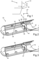
- Fig. 1 is an extremely schematic sectional view along a vehicle vertical direction (z-direction) or in a vehicle transverse direction (y-direction) sectional plane of a sill panel for a side sill 10 of a passenger car, not shown, and a side door 12 arranged above it and visible in detail for closing a corresponding door opening 14 shown.
- an outer side sill panel 16 extends outwards in the transverse direction of the vehicle (y-direction) to such an extent that - when the side door 12 is closed - it projects beyond an associated door lower edge 18 or an outer panel 20 of the side door 12 or at least flush with it completes.
- Such an extension of the outer side sill panel 16 has the advantage that - based on the overlap in the vehicle transverse direction (y direction) - the underside of the lower edge of the door 18 or the entire side door 12 prevents damage from stone chips or general contamination of the lower edge of the door 18 or an entire lower one Area of the side door 12 can be avoided.
- the general design of the described side sill 10 or in particular the outer side sill panel 16 raises the problem of difficult entry and exit into or out of the motor vehicle via the door opening 14, particularly for older people or for people with limited mobility.
- the problem is exacerbated if the vehicle door 12 cannot be opened wide enough, for example in tight parking conditions. Particularly in such situations, it can be uncomfortable to get in and out or the resulting soiling of clothing, especially trouser legs or the like.
- a cladding device is provided in the present case, which will be described below using the Fig. 2 to 6 in the respective perspective view or in the 7 and 8 is shown in respective sectional views along a sectional plane running in the vehicle vertical direction (z-direction) or in the vehicle transverse direction (y-direction).
- outer side sill panel 16 which is formed, for example, from a dimensionally stable plastic and by means of which a side sill part on the bodyshell side that is no longer recognizable is covered outwards or downwards - i.e. in the vehicle transverse direction (y direction) and in the vehicle vertical direction (z direction). is covered.
- an inherently rigid, outer cladding element 24 is provided in a length region 22 of the side sill 10, which is located below the door opening 14, which is located between an in Fig. 2 recognizable cladding position and an in Fig. 6 recognizable release position can be moved in a manner described in more detail below.
- the Fig. 3 to 5 show intermediate positions of the cladding element 24, which this moves during its displacement movement between the cladding position ( Fig. 1 ) and the release position ( Fig. 6 ) takes. They show about this 7 and 8 the cladding element 24 in its two end positions, namely the cladding position in Fig. 7 and the release position in Fig. 8 .
- the inherently rigid cladding element 24 can be pivoted about a bearing axis L which runs in the extension direction or at least substantially in the vehicle longitudinal direction (x direction), which is located in a lower portion 26 of the cladding element 24. Accordingly, especially when viewed together 7 and 8 It can also be seen that a displacement of the cladding element 24 from the cladding position ( Fig. 7 ) into the release position ( Fig. 8 ) leads to this being displaced inwards in the transverse direction of the vehicle (y-direction) over at least approximately the entire height of the side sill 10 or the outer side sill panel 16, in order to thereby simplify the entry and exit of a passenger via the corresponding door opening 14.
- a body element 63 which in the present case is a section of a body side wall which in the area of the side sill 10 at least partially covers it from above and possibly on the outside.
- this can also be an interior cladding element which covers the bodyshell part of the side sill 10 from the vehicle interior.
- the cladding device comprises an approximately U-shaped cladding part 30 in its base area, into which the cladding element 24 is integrated at least essentially flush with the surface in its cladding position.
- This trim part 30 is arranged to overlap with the front outer side sill trim 16 shown here and a rear outer side sill trim (not shown), the trim device being arranged in the said length range 22 below the associated door opening 14 of the corresponding side door 12.
- respective bearing webs 32, 34 protrude from the front and back of the cladding element 24, which extend at least substantially in the vehicle vertical direction (z-direction) and in the vehicle transverse direction (y-direction).
- a drive rod 36 is rotatably mounted on these bearing webs 32, 34, which extends at least substantially in the longitudinal direction of the vehicle (x direction) and approximately horizontally.
- This drive rod 36 comprises, in its respective end regions near the bearing webs 32, 34, a corresponding, U-shaped bend 37, which engages with an associated, slot-shaped link 38 of a corresponding link element 40, which in turn is on the inside of the cladding element 24 on the front or attached to the rear end.
- a rotation of the drive rod 36 therefore causes the desired displacement movement of the cladding element 24 between the cladding position according to the interaction of the respective offset 37 with the corresponding link 38 of the corresponding link element 40 Fig. 2 and 7 and in accordance with the release status Fig. 6 and 8th around the bearing axis L.
- the bearing axis L of the cladding element 24 is formed in the present case by respective bearing elements 42, 44, which on the one hand are fastened on the inside of the cladding element 24 and on the other hand on the inside of the cladding part 30.
- Each of these pairs of Bearing elements 42, 44 are pivotally connected to one another by a bolt or the like, the bolts of these pairs of bearing elements 42, 44 forming the bearing axis L of the cladding element 24.
- an angle strip element 46 is held displaceably at the upper end region 27 of the cladding element 24, which is in the cladding position according to Fig. 7 extends along an upper end edge 48 of the cladding element 24 and which is positively controlled in a manner described in more detail below during the displacement movement of the cladding element 24 from the cladding position into the release position - and back - also into its release position Fig. 8 is relocated.
- the angle strip element 46 is therefore arranged on the top side of the cladding element 24 and extends with one leg 50 horizontally and in the vehicle transverse direction (y-direction) outwards, and with one leg 52 at least substantially vertically and in the vehicle vertical direction (z-direction) upwards.
- the angle strip element 46 is arranged essentially below the upper end region 28 of the cladding element 24, with the leg 52 extending downwards in the vehicle vertical direction (z direction) and the leg 50 extending inwards in the vehicle transverse direction (y direction).
- the displacement movement of the angle strip element 46 between its two end positions - the release position and the cladding position - takes place in a positively controlled manner with the displacement movement of the cladding element 24.
- the angle strip element 46 is arranged via respective bearing elements 54, 56, which are arranged on the inside of the cladding element 24 or on the inside of the angle strip element 46 , can be moved around a bearing axis W.
- Each of the bearing webs 32, 34 also includes, on the respective inside facing the cladding element 24, a link 58, which in the present case is designed approximately L-shaped and into which a bearing pin 60 of the respective associated bearing element 56, which is connected to the angle strip element 46, is inserted. is engaged.
- a summary of the Fig. 2 to 6 shows that the bearing pin 60 runs along the L-shaped link 58 during the displacement movement of the cladding element 24 and thus causes the displacement or pivoting movement of the angle strip element 46 from its cladding position into its release position.
- a flexible cladding element 62 is provided, one end 64 of which is arranged at least indirectly - namely in the present case via the angle strip element 46 - on the inherently rigid cladding element 24.
- the other end 66 of the flexible cladding element 62 is attached to the body element 63 in the present case.
- the flexible cladding element 62 thus covers a free space 68 between the inherently rigid cladding element 24, which is in the cladding position, and the body element 63.
- the flexible cladding element 62 is formed from a fabric material, for example a fabric panel such as is used in the tops of convertibles.
- a fabric panel such as is used in the tops of convertibles.
- other configurations would also be conceivable here, such as a lamella-like or telescopically displaceable system of several cover elements.
- the flexible cladding element 62 In the cladding position, the flexible cladding element 62 is arranged in an area of the side sill 10 that is covered by the associated vehicle door.
- the flexible cladding element 62 is virtually stretched, that is, it covers the free space 68 arranged underneath without folds and thus prevents, on the one hand, the ingress of dirt and, on the other hand, the inflow of air while the motor vehicle is driving, which could lead to annoying noises.
- the flexible cladding element 62 thus serves, among other things, to cover the free space 68, for example to avoid contamination of clothing or a clear view into the free space 68. In addition, dirt entry into the free space 68 can also be avoided.
- a further advantage of the flexible cladding element 62 is that the NHV behavior in the interior of the motor vehicle is improved by avoiding corresponding noises or the like, which could enter the interior of the motor vehicle, for example via the free space 68. Finally, the flexible trim element 62 also improves the overall NHV behavior of the vehicle.
- the angle strip element 46 is designed in this way and in its cladding position according to Fig. 7 arranged that this has a receiving recess 70 for the lower edge of the door 18 of the associated side door 12. This ensures further improved protection of the lower edge of the door 18 and improved aerodynamics of the vehicle.
- the cladding element 24 and the angle strip element 46 can be driven, for example, by an electric motor, hydraulically or pneumatically by correspondingly driving the drive rod 36.
- a coupling can be linked to the opening of the side door or the opening or closing of a locking system of the vehicle.
- other couplings are also conceivable.
Landscapes
- Engineering & Computer Science (AREA)
- Mechanical Engineering (AREA)
- Chemical & Material Sciences (AREA)
- Combustion & Propulsion (AREA)
- Transportation (AREA)
- Body Structure For Vehicles (AREA)
- Vehicle Interior And Exterior Ornaments, Soundproofing, And Insulation (AREA)
- Lock And Its Accessories (AREA)
Claims (9)
- Dispositif de revêtement pour une jupe latérale (10) d'une voiture de tourisme, comportant un élément de revêtement (24) externe intrinsèquement rigide disposé dans une zone longitudinale (22) de la jupe latérale (10) en dessous d'une ouverture de porte (14), lequel élément de revêtement peut pivoter autour d'un axe de palier (L) s'étendant dans la direction longitudinale de véhicule (x) entre une position de revêtement et une position de libération et recouvre vers l'extérieur une partie de jupe latérale côté carrosserie dans la direction transversale de véhicule (y), un élément de revêtement flexible étant prévu, dont une extrémité est disposée au moins indirectement au niveau de l'élément de revêtement intrinsèquement rigide et peut être déplacée conjointement avec l'élément de revêtement intrinsèquement rigide, lors d'un mouvement de déplacement, entre la position de revêtement et la position de libération,
caractérisé en ce que
l'axe de palier (L) est situé dans une zone partielle inférieure (26) de l'élément de revêtement (24), en ce que l'élément de revêtement (62) flexible est disposé, dans le cas d'un élément de revêtement (24) externe disposé dans la position de revêtement, dans une zone de la jupe latérale (10) recouverte par une porte de véhicule (12) associée à l'ouverture de porte (14), et en ce que, dans le cas d'un élément de revêtement (24) externe disposé dans la position de revêtement, une fente entre l'extrémité, présentant l'élément de revêtement (62) flexible, de l'élément de revêtement (24) externe intrinsèquement rigide et un autre composant, ainsi qu'un espace libre (68) disposé sous celui-ci entre l'élément de revêtement (24) intrinsèquement rigide se trouvant dans la position de revêtement et un autre élément de revêtement ou une partie de carrosserie (63) sont recouverts. - Dispositif de revêtement selon la revendication 1,
caractérisé en ce que
un élément formant baguette est associé à l'élément de revêtement (24) intrinsèquement rigide, auquel élément formant baguette l'extrémité (64) correspondante de l'élément de revêtement (62) flexible est fixée. - Dispositif de revêtement selon la revendication 2,
caractérisé en ce que
l'élément formant baguette est associé à l'élément de revêtement (24) intrinsèquement rigide, lequel élément formant baguette peut être déplacé entre une position de revêtement, qu'il occupe dans la position de revêtement de l'élément de revêtement (24) intrinsèquement rigide, et une position de libération, qu'il occupe dans la position de libération de l'élément de revêtement (24) intrinsèquement rigide. - Dispositif de revêtement selon la revendication 3,
caractérisé en ce que
l'élément formant baguette est monté pivotant au niveau de l'élément de revêtement (24) intrinsèquement rigide. - Dispositif de revêtement selon l'une des revendications précédentes,
caractérisé en ce que
l'élément de revêtement (24) intrinsèquement rigide peut être déplacé vers l'intérieur, dans la direction transversale de véhicule, de la position de revêtement vers la position de libération. - Dispositif de revêtement selon l'une des revendications précédentes,
caractérisé en ce que
l'élément de revêtement (62) flexible, dans la position de revêtement, est disposé dans une zone de la jupe latérale (10) recouverte par une porte de véhicule associée. - Dispositif de revêtement selon l'une des revendications précédentes,
caractérisé en ce que
l'élément formant baguette présente un creux de réception (70) pour un bord inférieur des portes de véhicule associées. - Dispositif de revêtement selon l'une des revendications précédentes,
caractérisé en ce que
l'élément de revêtement (62) flexible est formé d'un matériau textile. - Voiture de tourisme comportant une jupe latérale (10) et un dispositif de revêtement selon l'une des revendications 1 à 8.
Applications Claiming Priority (2)
| Application Number | Priority Date | Filing Date | Title |
|---|---|---|---|
| DE102018001993.5A DE102018001993A1 (de) | 2018-03-13 | 2018-03-13 | Verkleidungseinrichtung für einen Seitenschweller eines Personenkraftwagens sowie Verfahren zum Betreiben einer derartigen Verkleidungseinrichtung |
| PCT/EP2018/083408 WO2019174767A1 (fr) | 2018-03-13 | 2018-12-04 | Dispositif de revêtement d'un bas de caisse d'un véhicule automobile et procédé pour faire fonctionner un tel dispositif de revêtement |
Publications (3)
| Publication Number | Publication Date |
|---|---|
| EP3765351A1 EP3765351A1 (fr) | 2021-01-20 |
| EP3765351C0 EP3765351C0 (fr) | 2023-10-25 |
| EP3765351B1 true EP3765351B1 (fr) | 2023-10-25 |
Family
ID=64664252
Family Applications (2)
| Application Number | Title | Priority Date | Filing Date |
|---|---|---|---|
| EP18815982.6A Active EP3765351B1 (fr) | 2018-03-13 | 2018-12-04 | Dispositif de revêtement d'un bas de caisse d'un véhicule automobile et procédé pour faire fonctionner un tel dispositif de revêtement |
| EP18815984.2A Active EP3765352B1 (fr) | 2018-03-13 | 2018-12-04 | Dispositif d'habillage pour un longeron latéral d'un véhicule particulier |
Family Applications After (1)
| Application Number | Title | Priority Date | Filing Date |
|---|---|---|---|
| EP18815984.2A Active EP3765352B1 (fr) | 2018-03-13 | 2018-12-04 | Dispositif d'habillage pour un longeron latéral d'un véhicule particulier |
Country Status (5)
| Country | Link |
|---|---|
| US (2) | US11325543B2 (fr) |
| EP (2) | EP3765351B1 (fr) |
| CN (2) | CN111836753B (fr) |
| DE (1) | DE102018001993A1 (fr) |
| WO (2) | WO2019174768A1 (fr) |
Families Citing this family (9)
| Publication number | Priority date | Publication date | Assignee | Title |
|---|---|---|---|---|
| DE102017000394A1 (de) * | 2017-01-18 | 2018-07-19 | Daimler Ag | Verkleidungsanordnung zur Verkleidung eines Karosserieelements eines Fahrzeugs |
| DE102018001993A1 (de) * | 2018-03-13 | 2019-09-19 | Daimler Ag | Verkleidungseinrichtung für einen Seitenschweller eines Personenkraftwagens sowie Verfahren zum Betreiben einer derartigen Verkleidungseinrichtung |
| USD909244S1 (en) * | 2018-09-16 | 2021-02-02 | Jaguar Land Rover Limited | Vehicle |
| DE102018009450B3 (de) * | 2018-12-04 | 2020-03-19 | Daimler Ag | Verkleidungseinrichtung für einen Seitenschweller eines Personenkraftwagens |
| DE102020003821A1 (de) | 2020-06-25 | 2021-12-30 | Daimler Ag | Verkleidungseinrichtung für einen Seitenschweller eines Personenkraftwagens |
| DE102020209130B4 (de) * | 2020-07-21 | 2023-05-11 | Magna Exteriors Gmbh | Verkleidungsanordnung zur Verkleidung eines Karosserieelements für ein Kraftfahrzeug, sowie ein Verfahren zur zwangsgesteuerten Verlagerung einer Luftleitvorrichtung einer Verkleidungsanordnung |
| EP4225614A4 (fr) * | 2020-10-08 | 2024-11-20 | Tiercon Corp. | Compartiment de stockage et d'aide de marche de pare-chocs composite rétractable |
| DE102020007140A1 (de) | 2020-11-23 | 2022-05-25 | Daimler Ag | Außenverkleidung für einen Kraftwagen |
| PL4339054T3 (pl) * | 2022-09-16 | 2026-03-23 | HÜBNER GmbH & Co. KG | Urządzenie do zmniejszania oporu aerodynamicznego pojazdów szynowych |
Family Cites Families (41)
| Publication number | Priority date | Publication date | Assignee | Title |
|---|---|---|---|---|
| JPS5649677U (fr) * | 1979-09-25 | 1981-05-01 | ||
| DE3613301A1 (de) * | 1986-04-19 | 1987-10-22 | Daimler Benz Ag | Seitenverkleidung fuer personen- oder kombinationskraftwagen |
| DE4209164C2 (de) * | 1992-03-20 | 2001-09-20 | Bayerische Motoren Werke Ag | Aerodynamische Verkleidung |
| US5678872A (en) * | 1996-04-08 | 1997-10-21 | Ford Global Technologies, Inc. | Concealable vehicle bumper step |
| US6158756A (en) * | 1998-07-07 | 2000-12-12 | Hansen; David Curtis | Maximum clearance high strength vehicle lower body protector that repositions to a vehicle entry or exit step |
| US6641158B2 (en) * | 2001-02-15 | 2003-11-04 | American Moto Products, Inc. | Retractable vehicle step |
| CA2436647C (fr) * | 2002-08-06 | 2011-07-12 | Decoma International Inc. | Marchepied motorise |
| US6742835B1 (en) * | 2003-06-02 | 2004-06-01 | General Motors Of Canada Limited | Rocker panel moldings |
| EP1568529A1 (fr) * | 2004-02-26 | 2005-08-31 | Ford Global Technologies, LLC | Tronçon inférieur d'encadrement de porte pour véhicule |
| US7318596B2 (en) * | 2004-05-03 | 2008-01-15 | Ventra Group Inc. | Retractable running board |
| DE102004045382A1 (de) * | 2004-09-18 | 2006-03-23 | Bayerische Motoren Werke Ag | Kraftfahrzeug mit einem Seitenschweller |
| DE102004051672A1 (de) * | 2004-10-22 | 2006-04-27 | Bayerische Motoren Werke Ag | Aerodynamische Verkleidung für ein Kraftfahrzeug |
| US7441790B2 (en) * | 2006-08-24 | 2008-10-28 | Ford Global Technologies, Llc | Deployable step and body-side assembly for a vehicle |
| US9944231B2 (en) * | 2006-10-27 | 2018-04-17 | Lund Motion Products, Inc. | Retractable vehicle step |
| US9701249B2 (en) * | 2006-10-27 | 2017-07-11 | Lund Motion Products, Inc. | Retractable vehicle step |
| CA2672678C (fr) * | 2006-12-13 | 2014-12-30 | Magna International Inc. | Panneau culbuteur mecaniquement retractable |
| KR100828785B1 (ko) * | 2006-12-14 | 2008-05-09 | 현대자동차주식회사 | 차량의 접이식 맵포켓구조 |
| US7513565B2 (en) * | 2007-01-26 | 2009-04-07 | Magna International Inc. | Power dual action rocker board |
| DE102007041538A1 (de) * | 2007-08-31 | 2009-03-05 | Daimler Ag | Verkleidungsanordnung für ein Karosseriebauteil eines Kraftwagens |
| DE102007062254A1 (de) * | 2007-12-21 | 2009-06-25 | GM Global Technology Operations, Inc., Detroit | Abstützung einer Einstiegsverkleidung an einem Trageelement eines Kraftfahrzeugs |
| DE102009031534A1 (de) | 2009-07-02 | 2010-02-11 | Daimler Ag | Verkleidungsanordnung |
| JP4926214B2 (ja) * | 2009-07-30 | 2012-05-09 | 株式会社ファルテック | 自動車用樹脂成形品 |
| DE102010048852A1 (de) * | 2010-10-19 | 2012-04-19 | Gm Global Technology Operations Llc (N.D.Ges.D. Staates Delaware) | Schwelleranordnung einer Kraftfahrzeugkarosserie |
| KR101284307B1 (ko) * | 2011-10-05 | 2013-07-08 | 현대자동차주식회사 | 차량용 수납장치 |
| DE102012018284A1 (de) * | 2012-09-14 | 2013-03-21 | Daimler Ag | Fahrzeug mit Längsträgerverkleidung |
| CN202806609U (zh) * | 2012-09-19 | 2013-03-20 | 富士重工业株式会社 | 车门装饰件 |
| KR101428301B1 (ko) * | 2012-12-21 | 2014-08-07 | 현대자동차주식회사 | 차량용 사이드 스텝의 작동 제어방법 |
| DE102014203175A1 (de) * | 2014-02-21 | 2015-08-27 | Bayerische Motoren Werke Aktiengesellschaft | Kraftfahrzeug |
| CA2939278C (fr) * | 2014-03-21 | 2020-10-27 | Magna International Inc. | Systeme de panneau lateral aerodynamique deployable |
| DE102014111075A1 (de) * | 2014-08-05 | 2016-02-11 | Dr. Ing. H.C. F. Porsche Aktiengesellschaft | Kraftfahrzeug mit einem einstellbaren Schweller |
| US9434317B2 (en) * | 2014-11-13 | 2016-09-06 | Ford Global Technologies, Llc | Vehicle step system |
| CN204870764U (zh) * | 2015-08-14 | 2015-12-16 | 力帆实业(集团)股份有限公司 | 轿车门槛翻转机构 |
| DE102015016538A1 (de) * | 2015-12-18 | 2017-06-22 | Gm Global Technology Operations, Inc. | Set aus einer ersten Türschwellenanordnung und einer zweiten Türschwellenanordnung für ein Fahrzeug, Fahrzeugpaar mit einem ersten und mit einem zweiten Fahrzeug und Verfahren zur Verankerung einer Verankerungsvorrichtung in einem Karosserieabschnitt der Türschwellenanordnung |
| DE102017000394A1 (de) * | 2017-01-18 | 2018-07-19 | Daimler Ag | Verkleidungsanordnung zur Verkleidung eines Karosserieelements eines Fahrzeugs |
| DE102017001303A1 (de) * | 2017-02-11 | 2017-12-21 | Daimler Ag | Verkleidungsanordnung zur Verkleidung eines Karosserieelements eines Fahrzeugs |
| DE102017001662A1 (de) | 2017-02-21 | 2017-08-17 | Daimler Ag | Verkleidungsanordnung zur Verkleidung eines Karosserieelements eines Fahrzeugs |
| US10150419B2 (en) * | 2017-03-29 | 2018-12-11 | Ford Global Technologies, Llc | Linkage for retractable running board |
| CN107187392A (zh) * | 2017-05-26 | 2017-09-22 | 广东东箭汽车用品制造有限公司 | 一种可升降踏板 |
| CN107351654B (zh) * | 2017-06-13 | 2019-07-23 | 浙江零跑科技有限公司 | 一种可翻转式外门槛饰板机构 |
| DE102018001993A1 (de) * | 2018-03-13 | 2019-09-19 | Daimler Ag | Verkleidungseinrichtung für einen Seitenschweller eines Personenkraftwagens sowie Verfahren zum Betreiben einer derartigen Verkleidungseinrichtung |
| US10814790B2 (en) * | 2018-06-26 | 2020-10-27 | Ford Global Technologies, Llc | Running board with roof access step and method |
-
2018
- 2018-03-13 DE DE102018001993.5A patent/DE102018001993A1/de not_active Withdrawn
- 2018-12-04 CN CN201880091167.XA patent/CN111836753B/zh active Active
- 2018-12-04 US US16/980,082 patent/US11325543B2/en active Active
- 2018-12-04 EP EP18815982.6A patent/EP3765351B1/fr active Active
- 2018-12-04 CN CN201880091164.6A patent/CN111836752B/zh active Active
- 2018-12-04 WO PCT/EP2018/083413 patent/WO2019174768A1/fr not_active Ceased
- 2018-12-04 EP EP18815984.2A patent/EP3765352B1/fr active Active
- 2018-12-04 US US16/980,091 patent/US11312318B2/en active Active
- 2018-12-04 WO PCT/EP2018/083408 patent/WO2019174767A1/fr not_active Ceased
Also Published As
| Publication number | Publication date |
|---|---|
| EP3765352B1 (fr) | 2023-10-11 |
| EP3765351C0 (fr) | 2023-10-25 |
| US11312318B2 (en) | 2022-04-26 |
| WO2019174767A1 (fr) | 2019-09-19 |
| EP3765351A1 (fr) | 2021-01-20 |
| DE102018001993A1 (de) | 2019-09-19 |
| EP3765352A1 (fr) | 2021-01-20 |
| WO2019174768A1 (fr) | 2019-09-19 |
| US20210024014A1 (en) | 2021-01-28 |
| US11325543B2 (en) | 2022-05-10 |
| CN111836752A (zh) | 2020-10-27 |
| CN111836752B (zh) | 2023-05-05 |
| US20210016724A1 (en) | 2021-01-21 |
| EP3765352C0 (fr) | 2023-10-11 |
| CN111836753A (zh) | 2020-10-27 |
| CN111836753B (zh) | 2022-07-12 |
Similar Documents
| Publication | Publication Date | Title |
|---|---|---|
| EP3765351B1 (fr) | Dispositif de revêtement d'un bas de caisse d'un véhicule automobile et procédé pour faire fonctionner un tel dispositif de revêtement | |
| EP3571095B1 (fr) | Ensemble d'habillage d'un élément de carrosserie d'un véhicule | |
| DE10039652A1 (de) | Verstärkungsstruktur einer Hecksäule eines Kraftfahrzeuges | |
| DE102018009450B3 (de) | Verkleidungseinrichtung für einen Seitenschweller eines Personenkraftwagens | |
| DE102008021265A1 (de) | Kraftfahrzeug mit A-Säule und in dieser gelagertem Airbag | |
| EP1262397B1 (fr) | Capot avant pour une voiture automobile | |
| DE102020209130A1 (de) | Verkleidungsanordnung zur Verkleidung eines Karosserieelements für ein Kraftfahrzeug, sowie ein Verfahren zur zwangsgesteuerten Verlagerung einer Luftleitvorrichtung einer Verkleidungsanordnung | |
| DE102010005834B4 (de) | Stützanordnung für eine Windschutzscheibe eines Personenkraftwagens | |
| EP4247669B1 (fr) | Revêtement externe pour véhicule automobile | |
| EP1254800B1 (fr) | Ensemble de toit pour vehicule | |
| DE19732699C2 (de) | Windabweiser für Kraftfahrzeuge | |
| DE60311717T2 (de) | Schiebedachanordnung für ein Fahrzeug | |
| EP3242807B1 (fr) | Toit destiné à un véhicule à moteur, notamment une voiture de tourisme | |
| EP0250807B1 (fr) | Voiture particulière à fonction multiple | |
| EP3571094B1 (fr) | Dispositif d'habillage de longeron de véhicule | |
| DE10345122A1 (de) | Fahrzeug, insbesondere PKW, mit offenem Aufbau | |
| EP1873017B1 (fr) | Paroi de véhicule | |
| DE102014003144B4 (de) | Scheibenwischeranordnung an Fahrzeugen, insbesondere an Kraftfahrzeugen | |
| EP2790940B1 (fr) | Système de retenue d'un élément d'aile, en particulier d'un capot, d'une trappe ou similaire, et d'un élément de revêtement sur une carrosserie de véhicule | |
| DE102018001024A1 (de) | Handschuhfacheinrichtung für einen Kraftwagen | |
| DE3333215A1 (de) | Windabweiser | |
| EP1995100B1 (fr) | Capote pour un cabriolet | |
| DE202022103350U1 (de) | Multifunktionales Sportrohr für ein Fahrzeug mit offenem Rahmen | |
| DE102010036670B4 (de) | Cabriolet-Fahrzeug | |
| DE4028251C1 (en) | Vehicle seat head restraint - has fixed facing section to cover recess in head restraints |
Legal Events
| Date | Code | Title | Description |
|---|---|---|---|
| STAA | Information on the status of an ep patent application or granted ep patent |
Free format text: STATUS: UNKNOWN |
|
| STAA | Information on the status of an ep patent application or granted ep patent |
Free format text: STATUS: THE INTERNATIONAL PUBLICATION HAS BEEN MADE |
|
| PUAI | Public reference made under article 153(3) epc to a published international application that has entered the european phase |
Free format text: ORIGINAL CODE: 0009012 |
|
| STAA | Information on the status of an ep patent application or granted ep patent |
Free format text: STATUS: REQUEST FOR EXAMINATION WAS MADE |
|
| 17P | Request for examination filed |
Effective date: 20200824 |
|
| AK | Designated contracting states |
Kind code of ref document: A1 Designated state(s): AL AT BE BG CH CY CZ DE DK EE ES FI FR GB GR HR HU IE IS IT LI LT LU LV MC MK MT NL NO PL PT RO RS SE SI SK SM TR |
|
| AX | Request for extension of the european patent |
Extension state: BA ME |
|
| DAV | Request for validation of the european patent (deleted) | ||
| DAX | Request for extension of the european patent (deleted) | ||
| RAP3 | Party data changed (applicant data changed or rights of an application transferred) |
Owner name: MERCEDES-BENZ GROUP AG |
|
| GRAP | Despatch of communication of intention to grant a patent |
Free format text: ORIGINAL CODE: EPIDOSNIGR1 |
|
| STAA | Information on the status of an ep patent application or granted ep patent |
Free format text: STATUS: GRANT OF PATENT IS INTENDED |
|
| INTG | Intention to grant announced |
Effective date: 20230713 |
|
| GRAS | Grant fee paid |
Free format text: ORIGINAL CODE: EPIDOSNIGR3 |
|
| GRAA | (expected) grant |
Free format text: ORIGINAL CODE: 0009210 |
|
| STAA | Information on the status of an ep patent application or granted ep patent |
Free format text: STATUS: THE PATENT HAS BEEN GRANTED |
|
| AK | Designated contracting states |
Kind code of ref document: B1 Designated state(s): AL AT BE BG CH CY CZ DE DK EE ES FI FR GB GR HR HU IE IS IT LI LT LU LV MC MK MT NL NO PL PT RO RS SE SI SK SM TR |
|
| REG | Reference to a national code |
Ref country code: GB Ref legal event code: FG4D Free format text: NOT ENGLISH |
|
| REG | Reference to a national code |
Ref country code: CH Ref legal event code: EP |
|
| REG | Reference to a national code |
Ref country code: DE Ref legal event code: R096 Ref document number: 502018013522 Country of ref document: DE |
|
| REG | Reference to a national code |
Ref country code: IE Ref legal event code: FG4D Free format text: LANGUAGE OF EP DOCUMENT: GERMAN |
|
| U01 | Request for unitary effect filed |
Effective date: 20231115 |
|
| U07 | Unitary effect registered |
Designated state(s): AT BE BG DE DK EE FI FR IT LT LU LV MT NL PT SE SI Effective date: 20231121 |
|
| U20 | Renewal fee for the european patent with unitary effect paid |
Year of fee payment: 6 Effective date: 20231226 |
|
| PG25 | Lapsed in a contracting state [announced via postgrant information from national office to epo] |
Ref country code: GR Free format text: LAPSE BECAUSE OF FAILURE TO SUBMIT A TRANSLATION OF THE DESCRIPTION OR TO PAY THE FEE WITHIN THE PRESCRIBED TIME-LIMIT Effective date: 20240126 |
|
| PG25 | Lapsed in a contracting state [announced via postgrant information from national office to epo] |
Ref country code: IS Free format text: LAPSE BECAUSE OF FAILURE TO SUBMIT A TRANSLATION OF THE DESCRIPTION OR TO PAY THE FEE WITHIN THE PRESCRIBED TIME-LIMIT Effective date: 20240225 |
|
| PG25 | Lapsed in a contracting state [announced via postgrant information from national office to epo] |
Ref country code: ES Free format text: LAPSE BECAUSE OF FAILURE TO SUBMIT A TRANSLATION OF THE DESCRIPTION OR TO PAY THE FEE WITHIN THE PRESCRIBED TIME-LIMIT Effective date: 20231025 |
|
| PG25 | Lapsed in a contracting state [announced via postgrant information from national office to epo] |
Ref country code: IS Free format text: LAPSE BECAUSE OF FAILURE TO SUBMIT A TRANSLATION OF THE DESCRIPTION OR TO PAY THE FEE WITHIN THE PRESCRIBED TIME-LIMIT Effective date: 20240225 Ref country code: GR Free format text: LAPSE BECAUSE OF FAILURE TO SUBMIT A TRANSLATION OF THE DESCRIPTION OR TO PAY THE FEE WITHIN THE PRESCRIBED TIME-LIMIT Effective date: 20240126 Ref country code: ES Free format text: LAPSE BECAUSE OF FAILURE TO SUBMIT A TRANSLATION OF THE DESCRIPTION OR TO PAY THE FEE WITHIN THE PRESCRIBED TIME-LIMIT Effective date: 20231025 |
|
| PG25 | Lapsed in a contracting state [announced via postgrant information from national office to epo] |
Ref country code: RS Free format text: LAPSE BECAUSE OF FAILURE TO SUBMIT A TRANSLATION OF THE DESCRIPTION OR TO PAY THE FEE WITHIN THE PRESCRIBED TIME-LIMIT Effective date: 20231025 Ref country code: PL Free format text: LAPSE BECAUSE OF FAILURE TO SUBMIT A TRANSLATION OF THE DESCRIPTION OR TO PAY THE FEE WITHIN THE PRESCRIBED TIME-LIMIT Effective date: 20231025 Ref country code: NO Free format text: LAPSE BECAUSE OF FAILURE TO SUBMIT A TRANSLATION OF THE DESCRIPTION OR TO PAY THE FEE WITHIN THE PRESCRIBED TIME-LIMIT Effective date: 20240125 Ref country code: HR Free format text: LAPSE BECAUSE OF FAILURE TO SUBMIT A TRANSLATION OF THE DESCRIPTION OR TO PAY THE FEE WITHIN THE PRESCRIBED TIME-LIMIT Effective date: 20231025 |
|
| PG25 | Lapsed in a contracting state [announced via postgrant information from national office to epo] |
Ref country code: CZ Free format text: LAPSE BECAUSE OF FAILURE TO SUBMIT A TRANSLATION OF THE DESCRIPTION OR TO PAY THE FEE WITHIN THE PRESCRIBED TIME-LIMIT Effective date: 20231025 |
|
| REG | Reference to a national code |
Ref country code: DE Ref legal event code: R097 Ref document number: 502018013522 Country of ref document: DE |
|
| PG25 | Lapsed in a contracting state [announced via postgrant information from national office to epo] |
Ref country code: SK Free format text: LAPSE BECAUSE OF FAILURE TO SUBMIT A TRANSLATION OF THE DESCRIPTION OR TO PAY THE FEE WITHIN THE PRESCRIBED TIME-LIMIT Effective date: 20231025 |
|
| PG25 | Lapsed in a contracting state [announced via postgrant information from national office to epo] |
Ref country code: SM Free format text: LAPSE BECAUSE OF FAILURE TO SUBMIT A TRANSLATION OF THE DESCRIPTION OR TO PAY THE FEE WITHIN THE PRESCRIBED TIME-LIMIT Effective date: 20231025 Ref country code: SK Free format text: LAPSE BECAUSE OF FAILURE TO SUBMIT A TRANSLATION OF THE DESCRIPTION OR TO PAY THE FEE WITHIN THE PRESCRIBED TIME-LIMIT Effective date: 20231025 Ref country code: RO Free format text: LAPSE BECAUSE OF FAILURE TO SUBMIT A TRANSLATION OF THE DESCRIPTION OR TO PAY THE FEE WITHIN THE PRESCRIBED TIME-LIMIT Effective date: 20231025 Ref country code: CZ Free format text: LAPSE BECAUSE OF FAILURE TO SUBMIT A TRANSLATION OF THE DESCRIPTION OR TO PAY THE FEE WITHIN THE PRESCRIBED TIME-LIMIT Effective date: 20231025 |
|
| REG | Reference to a national code |
Ref country code: CH Ref legal event code: PL |
|
| PG25 | Lapsed in a contracting state [announced via postgrant information from national office to epo] |
Ref country code: MC Free format text: LAPSE BECAUSE OF FAILURE TO SUBMIT A TRANSLATION OF THE DESCRIPTION OR TO PAY THE FEE WITHIN THE PRESCRIBED TIME-LIMIT Effective date: 20231025 |
|
| PG25 | Lapsed in a contracting state [announced via postgrant information from national office to epo] |
Ref country code: MC Free format text: LAPSE BECAUSE OF FAILURE TO SUBMIT A TRANSLATION OF THE DESCRIPTION OR TO PAY THE FEE WITHIN THE PRESCRIBED TIME-LIMIT Effective date: 20231025 |
|
| PLBE | No opposition filed within time limit |
Free format text: ORIGINAL CODE: 0009261 |
|
| STAA | Information on the status of an ep patent application or granted ep patent |
Free format text: STATUS: NO OPPOSITION FILED WITHIN TIME LIMIT |
|
| GBPC | Gb: european patent ceased through non-payment of renewal fee |
Effective date: 20240125 |
|
| 26N | No opposition filed |
Effective date: 20240726 |
|
| REG | Reference to a national code |
Ref country code: IE Ref legal event code: MM4A |
|
| PG25 | Lapsed in a contracting state [announced via postgrant information from national office to epo] |
Ref country code: IE Free format text: LAPSE BECAUSE OF NON-PAYMENT OF DUE FEES Effective date: 20231204 |
|
| PG25 | Lapsed in a contracting state [announced via postgrant information from national office to epo] |
Ref country code: GB Free format text: LAPSE BECAUSE OF NON-PAYMENT OF DUE FEES Effective date: 20240125 |
|
| PG25 | Lapsed in a contracting state [announced via postgrant information from national office to epo] |
Ref country code: CH Free format text: LAPSE BECAUSE OF NON-PAYMENT OF DUE FEES Effective date: 20231231 |
|
| PG25 | Lapsed in a contracting state [announced via postgrant information from national office to epo] |
Ref country code: IE Free format text: LAPSE BECAUSE OF NON-PAYMENT OF DUE FEES Effective date: 20231204 Ref country code: GB Free format text: LAPSE BECAUSE OF NON-PAYMENT OF DUE FEES Effective date: 20240125 Ref country code: CH Free format text: LAPSE BECAUSE OF NON-PAYMENT OF DUE FEES Effective date: 20231231 |
|
| U20 | Renewal fee for the european patent with unitary effect paid |
Year of fee payment: 7 Effective date: 20241225 |
|
| PG25 | Lapsed in a contracting state [announced via postgrant information from national office to epo] |
Ref country code: CY Free format text: LAPSE BECAUSE OF FAILURE TO SUBMIT A TRANSLATION OF THE DESCRIPTION OR TO PAY THE FEE WITHIN THE PRESCRIBED TIME-LIMIT; INVALID AB INITIO Effective date: 20181204 |
|
| PG25 | Lapsed in a contracting state [announced via postgrant information from national office to epo] |
Ref country code: HU Free format text: LAPSE BECAUSE OF FAILURE TO SUBMIT A TRANSLATION OF THE DESCRIPTION OR TO PAY THE FEE WITHIN THE PRESCRIBED TIME-LIMIT; INVALID AB INITIO Effective date: 20181204 |
|
| PG25 | Lapsed in a contracting state [announced via postgrant information from national office to epo] |
Ref country code: TR Free format text: LAPSE BECAUSE OF FAILURE TO SUBMIT A TRANSLATION OF THE DESCRIPTION OR TO PAY THE FEE WITHIN THE PRESCRIBED TIME-LIMIT Effective date: 20231025 |
|
| U20 | Renewal fee for the european patent with unitary effect paid |
Year of fee payment: 8 Effective date: 20251223 |