EP3765389B1 - Kettenförderkurve - Google Patents
Kettenförderkurve Download PDFInfo
- Publication number
- EP3765389B1 EP3765389B1 EP19719933.4A EP19719933A EP3765389B1 EP 3765389 B1 EP3765389 B1 EP 3765389B1 EP 19719933 A EP19719933 A EP 19719933A EP 3765389 B1 EP3765389 B1 EP 3765389B1
- Authority
- EP
- European Patent Office
- Prior art keywords
- conveyor
- curve
- tracks
- transport
- guiders
- Prior art date
- Legal status (The legal status is an assumption and is not a legal conclusion. Google has not performed a legal analysis and makes no representation as to the accuracy of the status listed.)
- Active
Links
Images



Classifications
-
- B—PERFORMING OPERATIONS; TRANSPORTING
- B65—CONVEYING; PACKING; STORING; HANDLING THIN OR FILAMENTARY MATERIAL
- B65G—TRANSPORT OR STORAGE DEVICES, e.g. CONVEYORS FOR LOADING OR TIPPING, SHOP CONVEYOR SYSTEMS OR PNEUMATIC TUBE CONVEYORS
- B65G21/00—Supporting or protective framework or housings for endless load-carriers or traction elements of belt or chain conveyors
- B65G21/16—Supporting or protective framework or housings for endless load-carriers or traction elements of belt or chain conveyors for conveyors having endless load-carriers movable in curved paths
-
- B—PERFORMING OPERATIONS; TRANSPORTING
- B65—CONVEYING; PACKING; STORING; HANDLING THIN OR FILAMENTARY MATERIAL
- B65G—TRANSPORT OR STORAGE DEVICES, e.g. CONVEYORS FOR LOADING OR TIPPING, SHOP CONVEYOR SYSTEMS OR PNEUMATIC TUBE CONVEYORS
- B65G15/00—Conveyors having endless load-conveying surfaces, i.e. belts and like continuous members, to which tractive effort is transmitted by means other than endless driving elements of similar configuration
- B65G15/10—Conveyors having endless load-conveying surfaces, i.e. belts and like continuous members, to which tractive effort is transmitted by means other than endless driving elements of similar configuration comprising two or more co-operating endless surfaces with parallel longitudinal axes, or a multiplicity of parallel elements, e.g. ropes defining an endless surface
-
- B—PERFORMING OPERATIONS; TRANSPORTING
- B65—CONVEYING; PACKING; STORING; HANDLING THIN OR FILAMENTARY MATERIAL
- B65G—TRANSPORT OR STORAGE DEVICES, e.g. CONVEYORS FOR LOADING OR TIPPING, SHOP CONVEYOR SYSTEMS OR PNEUMATIC TUBE CONVEYORS
- B65G17/00—Conveyors having an endless traction element, e.g. a chain, transmitting movement to a continuous or substantially-continuous load-carrying surface or to a series of individual load-carriers; Endless-chain conveyors in which the chains form the load-carrying surface
- B65G17/06—Conveyors having an endless traction element, e.g. a chain, transmitting movement to a continuous or substantially-continuous load-carrying surface or to a series of individual load-carriers; Endless-chain conveyors in which the chains form the load-carrying surface having a load-carrying surface formed by a series of interconnected, e.g. longitudinal, links, plates, or platforms
- B65G17/08—Conveyors having an endless traction element, e.g. a chain, transmitting movement to a continuous or substantially-continuous load-carrying surface or to a series of individual load-carriers; Endless-chain conveyors in which the chains form the load-carrying surface having a load-carrying surface formed by a series of interconnected, e.g. longitudinal, links, plates, or platforms the surface being formed by the traction element
- B65G17/086—Conveyors having an endless traction element, e.g. a chain, transmitting movement to a continuous or substantially-continuous load-carrying surface or to a series of individual load-carriers; Endless-chain conveyors in which the chains form the load-carrying surface having a load-carrying surface formed by a series of interconnected, e.g. longitudinal, links, plates, or platforms the surface being formed by the traction element specially adapted to follow a curved path
-
- B—PERFORMING OPERATIONS; TRANSPORTING
- B65—CONVEYING; PACKING; STORING; HANDLING THIN OR FILAMENTARY MATERIAL
- B65G—TRANSPORT OR STORAGE DEVICES, e.g. CONVEYORS FOR LOADING OR TIPPING, SHOP CONVEYOR SYSTEMS OR PNEUMATIC TUBE CONVEYORS
- B65G17/00—Conveyors having an endless traction element, e.g. a chain, transmitting movement to a continuous or substantially-continuous load-carrying surface or to a series of individual load-carriers; Endless-chain conveyors in which the chains form the load-carrying surface
- B65G17/30—Details; Auxiliary devices
- B65G17/38—Chains or like traction elements; Connections between traction elements and load-carriers
-
- B—PERFORMING OPERATIONS; TRANSPORTING
- B65—CONVEYING; PACKING; STORING; HANDLING THIN OR FILAMENTARY MATERIAL
- B65G—TRANSPORT OR STORAGE DEVICES, e.g. CONVEYORS FOR LOADING OR TIPPING, SHOP CONVEYOR SYSTEMS OR PNEUMATIC TUBE CONVEYORS
- B65G21/00—Supporting or protective framework or housings for endless load-carriers or traction elements of belt or chain conveyors
- B65G21/20—Means incorporated in, or attached to, framework or housings for guiding load-carriers, traction elements or loads supported on moving surfaces
- B65G21/22—Rails or the like engaging sliding elements or rollers attached to load-carriers or traction elements
-
- B—PERFORMING OPERATIONS; TRANSPORTING
- B65—CONVEYING; PACKING; STORING; HANDLING THIN OR FILAMENTARY MATERIAL
- B65G—TRANSPORT OR STORAGE DEVICES, e.g. CONVEYORS FOR LOADING OR TIPPING, SHOP CONVEYOR SYSTEMS OR PNEUMATIC TUBE CONVEYORS
- B65G23/00—Driving gear for endless conveyors; Belt- or chain-tensioning arrangements
- B65G23/02—Belt- or chain-engaging elements
- B65G23/04—Drums, rollers, or wheels
-
- B—PERFORMING OPERATIONS; TRANSPORTING
- B65—CONVEYING; PACKING; STORING; HANDLING THIN OR FILAMENTARY MATERIAL
- B65G—TRANSPORT OR STORAGE DEVICES, e.g. CONVEYORS FOR LOADING OR TIPPING, SHOP CONVEYOR SYSTEMS OR PNEUMATIC TUBE CONVEYORS
- B65G23/00—Driving gear for endless conveyors; Belt- or chain-tensioning arrangements
- B65G23/02—Belt- or chain-engaging elements
- B65G23/04—Drums, rollers, or wheels
- B65G23/06—Drums, rollers, or wheels with projections engaging abutments on belts or chains, e.g. sprocket wheels
-
- B—PERFORMING OPERATIONS; TRANSPORTING
- B65—CONVEYING; PACKING; STORING; HANDLING THIN OR FILAMENTARY MATERIAL
- B65G—TRANSPORT OR STORAGE DEVICES, e.g. CONVEYORS FOR LOADING OR TIPPING, SHOP CONVEYOR SYSTEMS OR PNEUMATIC TUBE CONVEYORS
- B65G23/00—Driving gear for endless conveyors; Belt- or chain-tensioning arrangements
- B65G23/02—Belt- or chain-engaging elements
- B65G23/04—Drums, rollers, or wheels
- B65G23/12—Arrangements of co-operating drums or rollers to augment tractive effort applied to the belts
-
- B—PERFORMING OPERATIONS; TRANSPORTING
- B65—CONVEYING; PACKING; STORING; HANDLING THIN OR FILAMENTARY MATERIAL
- B65G—TRANSPORT OR STORAGE DEVICES, e.g. CONVEYORS FOR LOADING OR TIPPING, SHOP CONVEYOR SYSTEMS OR PNEUMATIC TUBE CONVEYORS
- B65G15/00—Conveyors having endless load-conveying surfaces, i.e. belts and like continuous members, to which tractive effort is transmitted by means other than endless driving elements of similar configuration
- B65G15/02—Conveyors having endless load-conveying surfaces, i.e. belts and like continuous members, to which tractive effort is transmitted by means other than endless driving elements of similar configuration for conveying in a circular arc
Definitions
- the invention relates to a chain transport conveyor curve. More specifically, the invention relates to a chain conveyor curve with a small curvature radius. These curves typically have their own dedicated chain, spanning typically only the curve and thus having a transfer at the intake and offtake ends of the chain to straight or less curved sections of a conveying system.
- conveyors are frequently used for transportation of bottles, cans, various kinds of good, such as edible products, potable products and or other goods.
- the pitch of the individual links is greater at the outer circumference of the bend and smaller at the inner circumference of the bend.
- dedicated curved tracks are used, equipped with dedicated chain links that are typically wedged shaped, where the outer lateral side of the conveyor chain comprises the wider portions of the individual links and the inner lateral side of the conveyor chain comprises the smaller width portions of the individual links.
- this dedicated conveyor chain can only move in the bend, and is not suited to move through straight parts of the conveying system.
- the curved section of this conveyor comprises a return part, moving below the transport part of the conveyor chain.
- conical members such as a conical return idler or a conical drive is arranged.
- a set of fixed return guiders can be arranged around which the conveyor chain can be guided.
- the transport part and the return part are moving along a similar track, being held in place amongst others by two conical members or a set of return guiders.
- a serious draw back of these chains is that when broader chains are needed, the width of the individual chain links at the outer curve side of the chain tend to get relative large, resulting in a bumpy, ratcheting unsmooth transfer, a phenomenon also known as the polygon effect. Furthermore, the wider the chain links, the larger the diameter of the conical members or guiders at both the intake and offload side of the chain need to be, in order to guide the chain. A larger diameter of the conical members or of the return guiders leads to a larger gap between the corresponding feed in and offtake conveyors.
- the rotating axis of the conical member needs to be pointing towards the centre point of radius of the curve in order to have a smooth motion of the conveyor belt. Yet when broad conveyor chains are used, the outer side of the conical member needs a larger diameter and thus more space at the outside of the bend than at the inside, such that gaps between feed in and offtake conveyors is wedge shaped. This effect also limits the width of the conveyor belt.
- a last effect that limits the width of the conveyor belt is the relative large width of the links at the outer side of the curve, leading to unsmooth, ratcheting or bumpy transferral of goods at the outer side of the curve, an effect known as polygon effect.
- the US patent 1,206,305 discloses corner conveyor enabling the transportation of articles like newspapers to be around a corner from one horizontal assembled belt to another.
- the products are forwarded by a plurality of linear narrow belts (3) to be deposited on several chains (20) that move with different speeds in concentric grooves (21).
- the chains protrude above concentric oriented bent strips between which strips the concentric grooves are allocated.
- An outer chain travels with a higher speed than the a chain adjacent inwardly thereof to carry the articles smoothly and evenly around the corner.
- the French patent application FR-A-2242311 discloses a conveyor belt curve with two conical return rollers.
- the return rollers become relative large in diameter at the outside of the curve,
- the polygon effect is occurring on the outside of the bend and the relative large openings between the individual links at the outer radius of the support surface are posing problems as well.
- This exact solution is limited in its operational width because of these effects.
- the object of the invention can be seen in providing a curved conveyor chain that is more practical in use, of which the gaps at intake and offload ends of the conveyor can remain relatively small, while the transporting width can be relatively wide and potentially be extended.
- This substantially equal contact angle of movement of the tracks with the rotating axis of the conical drive is configured in order to have the individual tracks move with a corresponding angular speed through the curve.
- the separate parallel tracks comprise wedge-shaped links, wherein the angle of the wedge of the wedge-shaped links is smaller of an outer track, when compared with the angle of the wedge of the wedge-shaped link of a more inner track.
- the conical drive can be arranged in a return part of the conveyor track. If the conical drive is arranged in the return part, below the transport surface, the separate individual tracks can have a corresponding angular velocity in the track, without the wide gap, which usually exists with a conical drive installed at one of the transfer sides of the conveyor, i.e. at the intake or the offload side.
- the conical drive is a conical drum or a series of drive gears or sprockets with a, towards the direction of the outside ascending diameter.
- a drum would make a better frictional transfer of motion than a set of sprocket wheels.
- a series of sprocket wheels would give a better transfer of motion.
- the drive gears or sprockets have an increasing diameter and/or number of teeth towards the outside of the curve. Since the links of the individual separate conveyor tracks have different pitch angles relative to the pitch angles of the links of the other separate conveyor tracks, the number of teeth on the sets of sprocket wheels need to be adapted as well. Thus, the outer sets of sprocket wheels, on the curve outside typically have more teeth than the sets of sprocket wheels on the inside. By the different diameter and number of teeth, the individual conveyor tracks move in a substantially corresponding angular velocity through the curve.
- the returns of the conveyor comprise a series of idlers, wherein each parallel track comprises its own set of idlers.
- each set of idlers increases towards the outside of the curve in order to compensate for the differences in path length of the individual conveyor tracks.
- the diameter of the idlers towards the curve outside can be of comparable diameter resulting in that the transfer of the conveyor can approximate a cylindrical transfer.
- the returns can comprise a series of guiders, wherein the guiders can comprise two rounded edges.
- the rounded edges are placed one above the other, and can guide the individual tracks around a first rounded edge from a laying plane, in a direction downward, and around a second rounded edge again in a laying plane, moving back in opposite direction.
- the distance between the rounded edges from each guider increases towards the outside of the curve, in order to compensate for the differences in path length of the individual conveyor tracks.
- the idlers or guiders of the individual conveyor tracks are configured to run independently from the idlers of the other conveyor tracks. Since the angular speed of the separate tracks is the same, and the length of the individual tracks is larger towards the curve outside, the idlers each rotate in a different rotation velocity.
- the individual links of the chain can comprise two sets of hinging pin engaging elements, one set being configured for engaging a leading side hinging pin and one set being configured for engaging a trailing side hinging pin, wherein the two sets of hinging pin engaging elements are connected to a support structure, and wherein the support structure extends on a first side, e.g. a transport surface side relative to the hinging pin engaging elements and the support structure does not extend beyond the hinging pin engaging elements on a second side.
- the hinging pins when inserted and keeping together two consecutive links, can at sections in between the hinging pin engaging elements, move and be guided, supported and/or borne by guiders, or guiding surfaces.
- the tracks of the transport conveyor can guide smoothly, supported on the hinging pins.
- the hinging pins have a relative low friction contact surface with the guiders or guiding surfaces, mainly due to their relative small diameter.
- the total friction will be relative low, such that less friction losses may occur and less drive power may be needed.
- wear of the links and the support structure and the guiding surfaces or guiders may be reduced.
- the hinging pin engaging elements can comprise a series of ring structures, arranged slanted relative to the transport surface, wherein the ring structures comprise two series of aligned, slanted rings, each configured to engage a hinging pin.
- the manufacturing of the individual links may be less complex.
- these links are manufactured by means of injection molding.
- Rings with openings substantially perpendicular to the the opening direction of the mold by nature comprise undercut sections and require slides or pin inserts in the mold in order to be able to mold the links.
- the rings By sufficiently slanting the ring containing elements, the rings may be formed, while no undercut is present. Thus no pin inserts or slides may be necessary, which could greatly simplify the molds needed.
- Consecutive links in the chain can have hinging pin stoppers on alternating lateral sides of the chain, such that a hinging pin is facing at its first abutting side a first stopper from a first link and at its second abutting side a second stopper from a second link.
- each conveyor track is guided by a set of guiders, configured to allow the hinging pins of the conveyor chain to slide along.
- the tracks are born on the hinging pins, possibly reducing wear and friction as indicated herein above.
- the guiders can comprise two rounded edges, configured to guide the tracks around, wherein the distance between the rounded edges increases towards the curve outside of the transport conveyor. Since the hinging pins can slide over the guiders, it further simplifies the design and manufacture of the transport conveyor, while it may reduce wear and possibly, the needed drive power.
- the radius of the edges of set the guiders of each track increases towards the curve outside of the conveyor track and the average diameter of the rounded edges of the sets of guiders of each individual parallel tracks is substantially equal compared to the other tracks.
- the sliders of each track need to mimic the shape of a set of conical idlers.
- the outside guider for each track need to have an increased diameter on the curve outside position.
- the average radius of the rounded edges of the parallel tracks may be chosen substantially equal, such that the gaps at the intake and offload end remain relatively small.
- the distance between the two rounded edges of the guiders may need to increase, in order to compensate for the higher track length of the tracks towards the curve outside of the transport conveyor.
- the conveyor chain is substantially borne by the hinging pins, moving over the guiders. Both in the curves and in the transport part of the individual conveyor tracks, the chains may be guided by the hinging pins sliding over guiders. This can reduce the friction forces and wear as indicated herein above.
- ring-shaped is to be considered as, yet not to be seen as limited to an open through-going space surrounded by material, irrespective of the shape.
- the material may be in the shape of a ring around the through going space, in the shape of an oval, a square, a long hole and/or any specific form suited for the purpose.
- Figure 1 depicts a schematic perspective view of a conventional curved path conveyor 1 for small radius turns.
- the conveyor 1 comprises a frame 2 having two guiding edges 3 and 4. Guiding edge 3 is located on the curve outside 14 and guiding edge 4 is located on the curve inside 15. In between the guiding edges 3 and 4 is located a support surface 5, comprising a set of curved supports 6A-D. On the curved supports 6A-D a transport chain 7 can slide, being kept in position in horizontal sense by the guiding edges 3 and 4.
- the conveyor chain 7 comprises a series of wedge shaped hinging links 8. The pitch 13 of the individual links is larger on the curve outside 14 than on the curve inside 15.
- the conveyor chain 7 is an endless loop, which for instructive purposes is partially removed.
- the loop runs between two turns around an idler 9B at a first side and a drive 9A at the other side.
- the drive comprises a series of sprocket wheels 11A-11E of increasing diameter towards the curve outside 14.
- the Teeth of the sprocket wheels 11A-11E engage with the hinging pins of the links 8. Since the links get wider towards the curve outside 14, the distance between the dents, accommodating the hinging pins, in the sprocket wheels get correspondingly larger as well towards the curve outside 14.
- typically the number of teeth per sprocket wheel of all the wheels is the same.
- the conveyor track 7 Since the shape of the conveyor track 7 is defined by wedge shaped links 8, the conveyor track 7 defines a segment of an annular shaped track, which comprises a return part below a transport part.
- the outer circumference of the conically shaped drive 9A and a line directed towards an imaginary centre point P defines a wedge-shaped gap 12, of which the diameter is increasing towards the curve inside 15. The larger the width 16 of the track and/or the tighter the curve, the larger the gap 12 will be at the curve inside 15.
- the size of this gap at the curve inside 15 can limit the width and the tightness of the curve of the conveyor 1. If the size gets to large, products to be transported on the conveyor 1 may fall through the gap or get stuck in the gap. This can lead to unintentionally product loss and downtime of the conveyor.
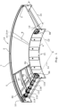
- the figures 2-5 depicts a schematic perspective view of a set of parallel conveyor tracks 7A, 7B and 7C of a conveyor 1.
- the tracks 7A, 7B and 7C comprise respectively wedge shaped links 8A, 8B and 8C.
- the tracks are driven by a set of sprocket wheels 24A-24F having an ascending diameter towards the curve outside 14.
- the pitch of the links 8A-C in the consecutive corresponding chain tracks 7A-C are substantially corresponding.
- the pitch of the links of the individual tracks in relation to each other would lie within approximately a margin of 50%. This provides the advantage that the idlers 17A-C, 18A-C, 21A-C and 22A-C where the chain tracks 7A-C turn, can be each of a limited diameter.
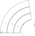
- the gap 12B, shown in figure 4 , between the lines L1 and the outer circumference of the idlers 18A-C can be reduced, when compared with the gap 12 between line L1 and the outer circumference of idler 9B and the line L1, shown in figure 1 .
- the idlers 18A-C, 19A-C, 20A-C, 21A-C, 22A-C are each individually and separately from the other idlers rotatable. Typically, the idlers 18C-22C on the curve outside 14 will rotate faster than the idlers 18A-22A on the curve inside 15.
- the chain tracks 7A-7C are driven by a series of shaft mounted sprocket wheels 24A-24F.
- the sprocket wheels 24A-24F comprise an increasing diameter towards the curve outside 14, as is depicted in figure 3 and 5 .
- the sprocket wheels 24A-B, 24C-D, 24E-F are pairwise coupled to the individual conveyor chain tracks 7A, 7B and 7C respectively.
- the sprocket wheels 24A-B, 24C-D, 24E-F are pairwise comprising an increasing number of teeth 25A-B, 25C-D, 25E-F to accommodate the hinging pins of the links 8A, 8B and 8C respectively of the individual conveyor chain tracks 7A, 7B and 7C respectively.
- the contact angle between each of the individual conveyor chain tracks 7A-C and the sprocket wheels is substantially the same, in order to have the conveyor chain tracks 7A-7C each move with substantially the same angular speed through the curve of the conveyor 1.
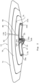
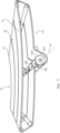
- FIG. 7 , 8 and 9 a set of two links is depicted in various views.
- the view of figure 9 is a front side view, indicated by arrow A in figures 7 and 8 .
- a set of two links 26 and 27 is depicted.
- the link 26 comprises two sets 28A-F and 29A-F of hinging pin engaging elements, connected to support structure 30.
- Each set comprises a set of aligned rings, such that a hinging pin e.g. 33 or 34 can be inserted.
- the rings of the hinging pin engaging elements comprise surfaces that are slanted relative to the transport surface 39 as is indicated in figure 9 .
- the line N is the axis perpendicular to the transport surface 39.
- O is an axis parallel to the slanted surface of the hinging pin engaging elements 28D.
- the angle ⁇ is chosen such, that the rings have no undercut portions seen in the direction of the line N.
- the hinging pins 33 find a stopper 35 of link 26 at a first lateral side of the chain, i.e. the curve outside 14 and a second stopper 36 of link 27 at a second lateral side of the chain, i.e. the curve inside 15.
- a link can be snapped in its operating position, if two consecutive links 26 and 27 are provided and linked together.
- the stoppers 36 or 35 need to be elastically deformed, such to allow the pin 33 to be inserted in the set of hinging pin engaging elements 29A-29H and 31A-31H of links 26 and 27 respectively. Once the end of the pin 33 is passed the stoppers 36 or 35, the stopper in question is allowed to snap back to its original undeformed state, therewith enclosing the pin 33 and avoiding the pin to escape.
- FIG 9 a front side view of the set of two links 26 and 27 is depicted.
- the support structure 30 of link 26, to which the hinging pin engaging elements 28A-H and 29A-H are attached extends beyond the hinging pin engaging elements 28A-H and 29A-H at a first side I, i.e. the side to which support surface 39 is facing.
- the support structure 30 does not extend beyond the hinging pin engaging elements 28A-H and 29A-H at a second side II. Thus, the support structure does not extend beyond the hinging pin 33. This allows the hinging 33 and 34 to rest on guiders 37 and 38 of the frame of the conveyor bend. Since the hinging pin engaging elements of the consecutive links are aligned in a transport direction A, all the links 26, 27 can be born on the hinging pins 33 and 34. Thus a smooth transport of the entire belt can be arranged, while the hinging pins are sliding over guiders.
- figure 10 is depicted a conveyor belt curve in which the set of return idlers 17A-C, 18A-C, 21A-C and 22A-C as depicted in the figures 2-4 can be replaced by a set of guiding shoes 40A-H.
- the guiding shoes 40A-H can allow a return of the individual conveyor tracks while the contact between the links 26 and 27 and the frame 2 predominantly is born by the hinging pins 33 and 34.
- Each of the guiding shoes 40A-H comprise two rounded edges, configured to guide the tracks around.
- the distance between the rounded edges increases towards the curve outside of the transport conveyor, such that a smooth transport of the chain over the guiders can be obtained.
- the outer belt track is allowed to travel a longer distance between the upper and lower rounded edges, such to compensate for its longer traveling path.
- drives are described as a set of sprocket wheels, alternatively, the drive may be a drum, where again the contact angle between the conveyor belt tracks and the drum are substantially equal for all the individual tracks.
- the links in the various embodiments are depicted as alternating links 26 and 27.
- a single-type-link belt for each track may be chosen, where the link engaging elements of the trailing side are sufficiently laterally offset from those hinging pin engaging elements of the leading side of the link, such that they fit in between each other and allow a hinging pin in.
- a first stopper and at a second lateral side a second stopper can be arranged such that the pins can only snap in when two links are connected by the pin.
Landscapes
- Engineering & Computer Science (AREA)
- Mechanical Engineering (AREA)
- Chain Conveyers (AREA)
Claims (12)
- Transportfördererkurve (1), umfassend mehrere getrennte, parallele, gekrümmte Förderbahnen (7A-7C);wobei die getrennten, parallelen, gekrümmten Förderbahnen (7A-7C) von einem konischen Antrieb (23, 24) angetrieben werden,wobei der Kontaktwinkel jeder der einzelnen Förderbahnen (7A-7C) mit einer konischen Trommel oder mit einer Reihe von Antriebsrädern oder -ritzeln (24A-24F) in Richtung der Außenseite (14) zunehmenden Durchmesser des konischen Antriebs (23, 24) im Vergleich zum Kontaktwinkel der anderen einzelnen Förderbahnen (7A-7C) im Wesentlichen gleich ist, um die einzelnen Förderbahnen (7A-7C) mit einer entsprechenden Winkeldrehzahl durch die Kurve zu bewegen,dadurch gekennzeichnet, dassdie getrennten, parallelen, gekrümmten Förderbahnen (7A-7C) keilförmige Glieder (8A-8C, 26, 27) umfassen,wobei der Winkel des Keils der keilförmigen Glieder (8A-8C, 26, 27) einer äußeren Förderbahn (7C) im Vergleich zum Winkel des Keils des keilförmigen Glieds (8A-8C, 26, 27) einer weiter innen liegenden Förderbahn (7A oder 7B) kleiner ist,und wobei das Untertrum der Transportfördererkurve eine Reihe Tragrollen (17A-17C, 18A-18C, 21A-21C, 22A-22C) oder Führungselemente (40A-40H) umfasst, wobei jede parallele Förderbahn (7A-7C) einen eigenen Satz Tragrollen (17A-17C, 18A-18C, 21A-21C, 22A-22C) oder Führungselemente (40A-40H) umfasst.
- Transportfördererkurve (1) nach Anspruch 1, wobei ein konischer Antrieb (23, 24) in einem Untertrumteil der Förderbahn angeordnet ist.
- Transportfördererkurve (1) nach Anspruch 1 oder 2, wobei die Antriebsräder (23, 24) oder -ritzel (24A-24F) eine zunehmende Anzahl Zähne (25A-25F) und/oder einen zunehmenden Durchmesser zur Außenseite (14) der Transportfördererkurve (1) hin aufweisen.
- Transportfördererkurve (1) nach einem der vorstehenden Ansprüche, wobei die Reihe Tragrollen (17A-17C, 18A-18C, 21A-21C, 22A-22C) oder Führungselemente (40A-40H) einen zunehmenden Abstand in vertikale Richtung jedes Satzes Tragrollen (17A-17C, 18A-18C, 21A-21C, 22A-22C) oder Führungselemente (40A-40H) zur Außenseite der Transportfördererkurve hin aufweist.
- Transportfördererkurve (1) nach einem der vorstehenden Ansprüche, wobei die Tragrollen (17A-17C, 18A-18C, 21A-21C, 22A-22C) der einzelnen Förderbahnen (7A-7C) dazu ausgelegt sind, unabhängig von den Tragrollen (17A-17C, 18A-18C, 21A-21C, 22A-22C) der anderen Förderbahnen (7A-7C) zu laufen.
- Transportfördererkurve (1) nach einem der vorstehenden Ansprüche, wobei die einzelnen Glieder (8A-8C, 26, 27) der Kette zwei Sätze Drehzapfeneingriffselemente (28A-28H, 29A-29H, 31A-31H, 32A-32H) umfassen, wobei ein Satz (28A-28H oder 31A-31H) für den Eingriff in einen Drehzapfen (33) auf der Vorderseite (A) ausgelegt ist und ein Satz für den Eingriff in einen Drehzapfen (29A-29H oder 32A-32H) auf der Rückseite ausgelegt ist, wobei die zwei Sätze Drehzapfeneingriffselemente (28A-28H, 29A-29H, 31A-31H, 32A-32H) mit einer Stützstruktur (30) verbunden sind und wobei sich die Stützstruktur (30) auf einer ersten Seite, z. B. einer Transportflächenseite (I) in Bezug zu den Drehzapfeneingriffselementen (28A-28H, 29A-29H, 31A-31H, 32A-32H) erstreckt und sich die Stützstruktur (30) auf einer zweiten Seite (II) nicht über die Drehzapfeneingriffselemente (28A-28H, 29A-29H, 31A-31H, 32A-32H) hinaus erstreckt.
- Transportfördererkurve (1) nach Anspruch 6, wobei die Drehzapfeneingriffselemente (28A-28H, 29A-29H, 31A-31H, 32A-32H) eine Reihe Ringstrukturen umfassen, die in Bezug zur Transportfläche geneigt angeordnet sind, wobei die Ringstrukturen zwei Reihen ausgerichteter, geneigter Ringe umfassen, die jeweils dazu ausgelegt sind, in einen Drehzapfen (33, 34) einzugreifen.
- Transportfördererkurve (1) nach Anspruch 6 oder 7, wobei aufeinanderfolgende Glieder (26, 27) der Kette Drehzapfenstopper (35, 36) auf abwechselnden lateralen Seiten der Kette aufweisen, sodass ein Drehzapfen (33) auf seiner ersten Anschlagseite einem ersten Stopper (35) eines ersten Glieds (27) und auf seiner zweiten Anschlagseite einem zweiten Stopper (36) eines zweiten Glieds (26) zugewandt ist.
- Transportfördererkurve (1) nach Anspruch 6, wobei die Förderglieder (26, 27) jeder Förderbahn (7A-7C) von einem Satz Führungselemente (37, 38) geführt werden, die dazu ausgelegt sind, zuzulassen, dass die Drehzapfen (33, 34) der Förderkette entlang gleiten.
- Transportfördererkurve (1) nach Anspruch 9, wobei die Führungselemente (37, 38) zwei abgerundete Kanten (40A-40H) umfassen, die dazu ausgelegt sind, die Ketten der einzelnen Förderbahnen (7A-7C) herumzuführen, wobei die Abstände zwischen den abgerundeten Kanten zur Kurvenaußenseite (14) der Transportfördererkurve hin zunehmen.
- Transportfördererkurve (1) nach Anspruch 10, wobei der Radius der abgerundeten Kanten (40A-40H) des Satzes Führungselemente (37, 38) der einzelnen Ketten jeder parallelen, einzelnen Förderbahn (7A-7C) zur Kurvenaußenseite (14) der Transportfördererkurve hin zunimmt und der Durchschnittsradius der abgerundeten Kanten (40A-40H) der Sätze Führungselemente (37, 38) aller paralleler Förderbahnen (7A-7C) im Wesentlichen gleich ist.
- Transportfördererkurve (1) nach Anspruch 9, wobei die Förderkette im Wesentlichen von den Drehzapfen (33, 34) getragen wird und sich über die Führungselemente (37, 38) bewegt.
Applications Claiming Priority (2)
| Application Number | Priority Date | Filing Date | Title |
|---|---|---|---|
| NL2020605A NL2020605B1 (en) | 2018-03-16 | 2018-03-16 | Chain conveyor curve |
| PCT/NL2019/050126 WO2019177455A1 (en) | 2018-03-16 | 2019-02-27 | Chain conveyor curve |
Publications (3)
| Publication Number | Publication Date |
|---|---|
| EP3765389A1 EP3765389A1 (de) | 2021-01-20 |
| EP3765389B1 true EP3765389B1 (de) | 2024-10-09 |
| EP3765389C0 EP3765389C0 (de) | 2024-10-09 |
Family
ID=62817035
Family Applications (1)
| Application Number | Title | Priority Date | Filing Date |
|---|---|---|---|
| EP19719933.4A Active EP3765389B1 (de) | 2018-03-16 | 2019-02-27 | Kettenförderkurve |
Country Status (4)
| Country | Link |
|---|---|
| US (1) | US11186439B2 (de) |
| EP (1) | EP3765389B1 (de) |
| NL (1) | NL2020605B1 (de) |
| WO (1) | WO2019177455A1 (de) |
Families Citing this family (3)
| Publication number | Priority date | Publication date | Assignee | Title |
|---|---|---|---|---|
| NL2027908B1 (nl) * | 2021-04-01 | 2022-10-17 | Rexnord Flattop Europe Bv | Bochttransportinrichting, en gebruik van een transportmodule |
| US12330878B2 (en) | 2021-04-01 | 2025-06-17 | Rexnord Flattop Europe B.V. | Curve conveyor and use of a conveyor module |
| WO2023249745A1 (en) * | 2022-06-23 | 2023-12-28 | Laitram, L.L.C. | Short take-up belt conveyor |
Citations (2)
| Publication number | Priority date | Publication date | Assignee | Title |
|---|---|---|---|---|
| US1206305A (en) * | 1915-03-22 | 1916-11-28 | Lamson Co | Corner for conveyers. |
| US5415273A (en) * | 1993-11-12 | 1995-05-16 | Peterson; Myron A. | Arcuate path chain belt harvester |
Family Cites Families (13)
| Publication number | Priority date | Publication date | Assignee | Title |
|---|---|---|---|---|
| US1245941A (en) * | 1916-08-15 | 1917-11-06 | Walter E Mayo | Stand for electric irons. |
| US3620355A (en) * | 1969-10-28 | 1971-11-16 | Baker Perkins Inc | Corner conveyor |
| US3693780A (en) * | 1971-06-29 | 1972-09-26 | Joseph Fraioli Sr | Lateral-bend endless chain belt conveyor assembly |
| US3963780A (en) * | 1971-12-22 | 1976-06-15 | Sandoz, Inc. | N,N'-disubstituted-p-phenylenediamines |
| DE2321036C3 (de) * | 1973-04-26 | 1984-07-19 | Draadindustrie Jonge Poerink B.V., 7620 Borne | Plattenband aus Kunststoff |
| DE2343249C3 (de) * | 1973-08-28 | 1980-03-20 | Draadindustrie Jonge Poerink B.V., Borne (Niederlande) | Antrieb für einen aus wenigstens einem gekrümmten Förderband und einem weiteren Förderband bestehenden Förderer |
| US4887708A (en) * | 1989-01-23 | 1989-12-19 | Portec, Inc. | Drive apparatus for belt power turns |
| US5217110A (en) * | 1992-04-23 | 1993-06-08 | Cambridge Wire Cloth Company | Modular plastic turn belt conveyor system, module, belt and drive therefor |
| US5992615A (en) * | 1998-01-12 | 1999-11-30 | Muchalov; Ivan | Curved conveyor section |
| EP1457686B1 (de) * | 2003-03-14 | 2005-12-28 | Habasit AG | Kreuzklemmvorrichtung |
| US7131530B2 (en) * | 2005-01-27 | 2006-11-07 | Transnorm System Inc. | Interlocker for a conveyor belt and method of utilizing an interlocker for a conveyor belt |
| US7832549B2 (en) * | 2006-02-08 | 2010-11-16 | Thermodrive Llc | Curved conveyor with guide for preventing radial belt migration |
| DE102011100043A1 (de) * | 2011-04-29 | 2012-10-31 | Interroll Holding Ag | Kurvengurtförderer |
-
2018
- 2018-03-16 NL NL2020605A patent/NL2020605B1/nl active
-
2019
- 2019-02-27 US US16/980,932 patent/US11186439B2/en active Active
- 2019-02-27 WO PCT/NL2019/050126 patent/WO2019177455A1/en not_active Ceased
- 2019-02-27 EP EP19719933.4A patent/EP3765389B1/de active Active
Patent Citations (2)
| Publication number | Priority date | Publication date | Assignee | Title |
|---|---|---|---|---|
| US1206305A (en) * | 1915-03-22 | 1916-11-28 | Lamson Co | Corner for conveyers. |
| US5415273A (en) * | 1993-11-12 | 1995-05-16 | Peterson; Myron A. | Arcuate path chain belt harvester |
Also Published As
| Publication number | Publication date |
|---|---|
| EP3765389A1 (de) | 2021-01-20 |
| WO2019177455A1 (en) | 2019-09-19 |
| US11186439B2 (en) | 2021-11-30 |
| US20200407169A1 (en) | 2020-12-31 |
| NL2020605B1 (en) | 2019-09-26 |
| EP3765389C0 (de) | 2024-10-09 |
Similar Documents
| Publication | Publication Date | Title |
|---|---|---|
| US7314132B2 (en) | Rodless conveyor belt or chain | |
| US12065313B2 (en) | Roller conveyor gap blocker | |
| EP2509895B1 (de) | Fördertransfersystem mit schwebender transferplattform | |
| US7963389B2 (en) | Conveyor | |
| CA2642513C (en) | Curved conveyor with guide for preventing radial belt migration | |
| CN107438573B (zh) | 具有传送带的输送系统 | |
| AU2007265273B2 (en) | Roller-belt conveyor with infeed pull-away | |
| US11186439B2 (en) | Chain conveyor curve | |
| NL2002878C2 (en) | A conveyor having parallel conveyor members. | |
| US6105755A (en) | Curved conveyor section | |
| TWI810286B (zh) | 曲線輸送帶 | |
| CN209922175U (zh) | 一种缝隙紧密的输送结构 | |
| US5038923A (en) | Mini-roller conveyor with variable pressure traction sleeve | |
| US10259654B2 (en) | Conveyor and a conveying system | |
| US11505409B2 (en) | Two-axis modular belt and conveyor | |
| EP3765388B1 (de) | Kettenglied für fördersystem |
Legal Events
| Date | Code | Title | Description |
|---|---|---|---|
| STAA | Information on the status of an ep patent application or granted ep patent |
Free format text: STATUS: UNKNOWN |
|
| STAA | Information on the status of an ep patent application or granted ep patent |
Free format text: STATUS: THE INTERNATIONAL PUBLICATION HAS BEEN MADE |
|
| PUAI | Public reference made under article 153(3) epc to a published international application that has entered the european phase |
Free format text: ORIGINAL CODE: 0009012 |
|
| STAA | Information on the status of an ep patent application or granted ep patent |
Free format text: STATUS: REQUEST FOR EXAMINATION WAS MADE |
|
| 17P | Request for examination filed |
Effective date: 20201016 |
|
| AK | Designated contracting states |
Kind code of ref document: A1 Designated state(s): AL AT BE BG CH CY CZ DE DK EE ES FI FR GB GR HR HU IE IS IT LI LT LU LV MC MK MT NL NO PL PT RO RS SE SI SK SM TR |
|
| AX | Request for extension of the european patent |
Extension state: BA ME |
|
| DAV | Request for validation of the european patent (deleted) | ||
| DAX | Request for extension of the european patent (deleted) | ||
| STAA | Information on the status of an ep patent application or granted ep patent |
Free format text: STATUS: EXAMINATION IS IN PROGRESS |
|
| 17Q | First examination report despatched |
Effective date: 20220822 |
|
| GRAP | Despatch of communication of intention to grant a patent |
Free format text: ORIGINAL CODE: EPIDOSNIGR1 |
|
| STAA | Information on the status of an ep patent application or granted ep patent |
Free format text: STATUS: GRANT OF PATENT IS INTENDED |
|
| INTG | Intention to grant announced |
Effective date: 20240529 |
|
| GRAS | Grant fee paid |
Free format text: ORIGINAL CODE: EPIDOSNIGR3 |
|
| GRAA | (expected) grant |
Free format text: ORIGINAL CODE: 0009210 |
|
| STAA | Information on the status of an ep patent application or granted ep patent |
Free format text: STATUS: THE PATENT HAS BEEN GRANTED |
|
| AK | Designated contracting states |
Kind code of ref document: B1 Designated state(s): AL AT BE BG CH CY CZ DE DK EE ES FI FR GB GR HR HU IE IS IT LI LT LU LV MC MK MT NL NO PL PT RO RS SE SI SK SM TR |
|
| REG | Reference to a national code |
Ref country code: CH Ref legal event code: EP |
|
| REG | Reference to a national code |
Ref country code: DE Ref legal event code: R096 Ref document number: 602019060037 Country of ref document: DE |
|
| REG | Reference to a national code |
Ref country code: IE Ref legal event code: FG4D |
|
| U01 | Request for unitary effect filed |
Effective date: 20241108 |
|
| U07 | Unitary effect registered |
Designated state(s): AT BE BG DE DK EE FI FR IT LT LU LV MT NL PT RO SE SI Effective date: 20241115 |
|
| U20 | Renewal fee for the european patent with unitary effect paid |
Year of fee payment: 7 Effective date: 20250227 |
|
| PG25 | Lapsed in a contracting state [announced via postgrant information from national office to epo] |
Ref country code: IS Free format text: LAPSE BECAUSE OF FAILURE TO SUBMIT A TRANSLATION OF THE DESCRIPTION OR TO PAY THE FEE WITHIN THE PRESCRIBED TIME-LIMIT Effective date: 20250209 Ref country code: HR Free format text: LAPSE BECAUSE OF FAILURE TO SUBMIT A TRANSLATION OF THE DESCRIPTION OR TO PAY THE FEE WITHIN THE PRESCRIBED TIME-LIMIT Effective date: 20241009 |
|
| PG25 | Lapsed in a contracting state [announced via postgrant information from national office to epo] |
Ref country code: ES Free format text: LAPSE BECAUSE OF FAILURE TO SUBMIT A TRANSLATION OF THE DESCRIPTION OR TO PAY THE FEE WITHIN THE PRESCRIBED TIME-LIMIT Effective date: 20241009 |
|
| PG25 | Lapsed in a contracting state [announced via postgrant information from national office to epo] |
Ref country code: NO Free format text: LAPSE BECAUSE OF FAILURE TO SUBMIT A TRANSLATION OF THE DESCRIPTION OR TO PAY THE FEE WITHIN THE PRESCRIBED TIME-LIMIT Effective date: 20250109 |
|
| PG25 | Lapsed in a contracting state [announced via postgrant information from national office to epo] |
Ref country code: GR Free format text: LAPSE BECAUSE OF FAILURE TO SUBMIT A TRANSLATION OF THE DESCRIPTION OR TO PAY THE FEE WITHIN THE PRESCRIBED TIME-LIMIT Effective date: 20250110 |
|
| PG25 | Lapsed in a contracting state [announced via postgrant information from national office to epo] |
Ref country code: PL Free format text: LAPSE BECAUSE OF FAILURE TO SUBMIT A TRANSLATION OF THE DESCRIPTION OR TO PAY THE FEE WITHIN THE PRESCRIBED TIME-LIMIT Effective date: 20241009 |
|
| PG25 | Lapsed in a contracting state [announced via postgrant information from national office to epo] |
Ref country code: RS Free format text: LAPSE BECAUSE OF FAILURE TO SUBMIT A TRANSLATION OF THE DESCRIPTION OR TO PAY THE FEE WITHIN THE PRESCRIBED TIME-LIMIT Effective date: 20250109 |
|
| PG25 | Lapsed in a contracting state [announced via postgrant information from national office to epo] |
Ref country code: SM Free format text: LAPSE BECAUSE OF FAILURE TO SUBMIT A TRANSLATION OF THE DESCRIPTION OR TO PAY THE FEE WITHIN THE PRESCRIBED TIME-LIMIT Effective date: 20241009 |
|
| PG25 | Lapsed in a contracting state [announced via postgrant information from national office to epo] |
Ref country code: SK Free format text: LAPSE BECAUSE OF FAILURE TO SUBMIT A TRANSLATION OF THE DESCRIPTION OR TO PAY THE FEE WITHIN THE PRESCRIBED TIME-LIMIT Effective date: 20241009 |
|
| PG25 | Lapsed in a contracting state [announced via postgrant information from national office to epo] |
Ref country code: CZ Free format text: LAPSE BECAUSE OF FAILURE TO SUBMIT A TRANSLATION OF THE DESCRIPTION OR TO PAY THE FEE WITHIN THE PRESCRIBED TIME-LIMIT Effective date: 20241009 |
|
| PLBE | No opposition filed within time limit |
Free format text: ORIGINAL CODE: 0009261 |
|
| STAA | Information on the status of an ep patent application or granted ep patent |
Free format text: STATUS: NO OPPOSITION FILED WITHIN TIME LIMIT |
|
| PG25 | Lapsed in a contracting state [announced via postgrant information from national office to epo] |
Ref country code: MC Free format text: LAPSE BECAUSE OF FAILURE TO SUBMIT A TRANSLATION OF THE DESCRIPTION OR TO PAY THE FEE WITHIN THE PRESCRIBED TIME-LIMIT Effective date: 20241009 |
|
| 26N | No opposition filed |
Effective date: 20250710 |
|
| REG | Reference to a national code |
Ref country code: CH Ref legal event code: PL |
|
| PG25 | Lapsed in a contracting state [announced via postgrant information from national office to epo] |
Ref country code: CH Free format text: LAPSE BECAUSE OF NON-PAYMENT OF DUE FEES Effective date: 20250228 |
|
| GBPC | Gb: european patent ceased through non-payment of renewal fee |
Effective date: 20250227 |
|
| PG25 | Lapsed in a contracting state [announced via postgrant information from national office to epo] |
Ref country code: GB Free format text: LAPSE BECAUSE OF NON-PAYMENT OF DUE FEES Effective date: 20250227 |
|
| PG25 | Lapsed in a contracting state [announced via postgrant information from national office to epo] |
Ref country code: IE Free format text: LAPSE BECAUSE OF NON-PAYMENT OF DUE FEES Effective date: 20250227 |
|
| U20 | Renewal fee for the european patent with unitary effect paid |
Year of fee payment: 8 Effective date: 20260227 |