EP3765718B1 - Verfahren zur einstellung des zustandes einer chemischen verarbeitungseinheit mit einer turbine - Google Patents
Verfahren zur einstellung des zustandes einer chemischen verarbeitungseinheit mit einer turbine Download PDFInfo
- Publication number
- EP3765718B1 EP3765718B1 EP19767299.1A EP19767299A EP3765718B1 EP 3765718 B1 EP3765718 B1 EP 3765718B1 EP 19767299 A EP19767299 A EP 19767299A EP 3765718 B1 EP3765718 B1 EP 3765718B1
- Authority
- EP
- European Patent Office
- Prior art keywords
- turbine
- resistance
- steady state
- process condition
- hydroprocessing reactor
- Prior art date
- Legal status (The legal status is an assumption and is not a legal conclusion. Google has not performed a legal analysis and makes no representation as to the accuracy of the status listed.)
- Active
Links
Images

Classifications
-
- C—CHEMISTRY; METALLURGY
- C10—PETROLEUM, GAS OR COKE INDUSTRIES; TECHNICAL GASES CONTAINING CARBON MONOXIDE; FUELS; LUBRICANTS; PEAT
- C10G—CRACKING HYDROCARBON OILS; PRODUCTION OF LIQUID HYDROCARBON MIXTURES, e.g. BY DESTRUCTIVE HYDROGENATION, OLIGOMERISATION, POLYMERISATION; RECOVERY OF HYDROCARBON OILS FROM OIL-SHALE, OIL-SAND, OR GASES; REFINING MIXTURES MAINLY CONSISTING OF HYDROCARBONS; REFORMING OF NAPHTHA; MINERAL WAXES
- C10G49/00—Treatment of hydrocarbon oils, in the presence of hydrogen or hydrogen-generating compounds, not provided for in a single one of groups C10G45/02, C10G45/32, C10G45/44, C10G45/58 or C10G47/00
- C10G49/26—Controlling or regulating
-
- F—MECHANICAL ENGINEERING; LIGHTING; HEATING; WEAPONS; BLASTING
- F01—MACHINES OR ENGINES IN GENERAL; ENGINE PLANTS IN GENERAL; STEAM ENGINES
- F01K—STEAM ENGINE PLANTS; STEAM ACCUMULATORS; ENGINE PLANTS NOT OTHERWISE PROVIDED FOR; ENGINES USING SPECIAL WORKING FLUIDS OR CYCLES
- F01K23/00—Plants characterised by more than one engine delivering power external to the plant, the engines being driven by different fluids
- F01K23/02—Plants characterised by more than one engine delivering power external to the plant, the engines being driven by different fluids the engine cycles being thermally coupled
- F01K23/06—Plants characterised by more than one engine delivering power external to the plant, the engines being driven by different fluids the engine cycles being thermally coupled combustion heat from one cycle heating the fluid in another cycle
- F01K23/064—Plants characterised by more than one engine delivering power external to the plant, the engines being driven by different fluids the engine cycles being thermally coupled combustion heat from one cycle heating the fluid in another cycle in combination with an industrial process, e.g. chemical, metallurgical
-
- F—MECHANICAL ENGINEERING; LIGHTING; HEATING; WEAPONS; BLASTING
- F01—MACHINES OR ENGINES IN GENERAL; ENGINE PLANTS IN GENERAL; STEAM ENGINES
- F01D—NON-POSITIVE DISPLACEMENT MACHINES OR ENGINES, e.g. STEAM TURBINES
- F01D15/00—Adaptations of machines or engines for special use; Combinations of engines with devices driven thereby
- F01D15/10—Adaptations for driving, or combinations with, electric generators
-
- F—MECHANICAL ENGINEERING; LIGHTING; HEATING; WEAPONS; BLASTING
- F01—MACHINES OR ENGINES IN GENERAL; ENGINE PLANTS IN GENERAL; STEAM ENGINES
- F01D—NON-POSITIVE DISPLACEMENT MACHINES OR ENGINES, e.g. STEAM TURBINES
- F01D17/00—Regulating or controlling by varying flow
- F01D17/10—Final actuators
- F01D17/12—Final actuators arranged in stator parts
- F01D17/14—Final actuators arranged in stator parts varying effective cross-sectional area of nozzles or guide conduits
- F01D17/16—Final actuators arranged in stator parts varying effective cross-sectional area of nozzles or guide conduits by means of nozzle vanes
-
- F—MECHANICAL ENGINEERING; LIGHTING; HEATING; WEAPONS; BLASTING
- F01—MACHINES OR ENGINES IN GENERAL; ENGINE PLANTS IN GENERAL; STEAM ENGINES
- F01D—NON-POSITIVE DISPLACEMENT MACHINES OR ENGINES, e.g. STEAM TURBINES
- F01D21/00—Shutting-down of machines or engines, e.g. in emergency; Regulating, controlling, or safety means not otherwise provided for
- F01D21/14—Shutting-down of machines or engines, e.g. in emergency; Regulating, controlling, or safety means not otherwise provided for responsive to other specific conditions
-
- C—CHEMISTRY; METALLURGY
- C10—PETROLEUM, GAS OR COKE INDUSTRIES; TECHNICAL GASES CONTAINING CARBON MONOXIDE; FUELS; LUBRICANTS; PEAT
- C10G—CRACKING HYDROCARBON OILS; PRODUCTION OF LIQUID HYDROCARBON MIXTURES, e.g. BY DESTRUCTIVE HYDROGENATION, OLIGOMERISATION, POLYMERISATION; RECOVERY OF HYDROCARBON OILS FROM OIL-SHALE, OIL-SAND, OR GASES; REFINING MIXTURES MAINLY CONSISTING OF HYDROCARBONS; REFORMING OF NAPHTHA; MINERAL WAXES
- C10G11/00—Catalytic cracking, in the absence of hydrogen, of hydrocarbon oils
- C10G11/14—Catalytic cracking, in the absence of hydrogen, of hydrocarbon oils with preheated moving solid catalysts
- C10G11/18—Catalytic cracking, in the absence of hydrogen, of hydrocarbon oils with preheated moving solid catalysts according to the "fluidised-bed" technique
- C10G11/187—Controlling or regulating
-
- F—MECHANICAL ENGINEERING; LIGHTING; HEATING; WEAPONS; BLASTING
- F05—INDEXING SCHEMES RELATING TO ENGINES OR PUMPS IN VARIOUS SUBCLASSES OF CLASSES F01-F04
- F05D—INDEXING SCHEME FOR ASPECTS RELATING TO NON-POSITIVE-DISPLACEMENT MACHINES OR ENGINES, GAS-TURBINES OR JET-PROPULSION PLANTS
- F05D2220/00—Application
- F05D2220/30—Application in turbines
- F05D2220/31—Application in turbines in steam turbines
-
- F—MECHANICAL ENGINEERING; LIGHTING; HEATING; WEAPONS; BLASTING
- F05—INDEXING SCHEMES RELATING TO ENGINES OR PUMPS IN VARIOUS SUBCLASSES OF CLASSES F01-F04
- F05D—INDEXING SCHEME FOR ASPECTS RELATING TO NON-POSITIVE-DISPLACEMENT MACHINES OR ENGINES, GAS-TURBINES OR JET-PROPULSION PLANTS
- F05D2220/00—Application
- F05D2220/60—Application making use of surplus or waste energy
- F05D2220/62—Application making use of surplus or waste energy with energy recovery turbines
-
- F—MECHANICAL ENGINEERING; LIGHTING; HEATING; WEAPONS; BLASTING
- F05—INDEXING SCHEMES RELATING TO ENGINES OR PUMPS IN VARIOUS SUBCLASSES OF CLASSES F01-F04
- F05D—INDEXING SCHEME FOR ASPECTS RELATING TO NON-POSITIVE-DISPLACEMENT MACHINES OR ENGINES, GAS-TURBINES OR JET-PROPULSION PLANTS
- F05D2220/00—Application
- F05D2220/70—Application in combination with
- F05D2220/72—Application in combination with a steam turbine
- F05D2220/722—Application in combination with a steam turbine as part of an integrated gasification combined cycle
-
- F—MECHANICAL ENGINEERING; LIGHTING; HEATING; WEAPONS; BLASTING
- F05—INDEXING SCHEMES RELATING TO ENGINES OR PUMPS IN VARIOUS SUBCLASSES OF CLASSES F01-F04
- F05D—INDEXING SCHEME FOR ASPECTS RELATING TO NON-POSITIVE-DISPLACEMENT MACHINES OR ENGINES, GAS-TURBINES OR JET-PROPULSION PLANTS
- F05D2220/00—Application
- F05D2220/70—Application in combination with
- F05D2220/76—Application in combination with an electrical generator
-
- F—MECHANICAL ENGINEERING; LIGHTING; HEATING; WEAPONS; BLASTING
- F05—INDEXING SCHEMES RELATING TO ENGINES OR PUMPS IN VARIOUS SUBCLASSES OF CLASSES F01-F04
- F05D—INDEXING SCHEME FOR ASPECTS RELATING TO NON-POSITIVE-DISPLACEMENT MACHINES OR ENGINES, GAS-TURBINES OR JET-PROPULSION PLANTS
- F05D2270/00—Control
- F05D2270/01—Purpose of the control system
- F05D2270/05—Purpose of the control system to affect the output of the engine
- F05D2270/052—Torque
-
- F—MECHANICAL ENGINEERING; LIGHTING; HEATING; WEAPONS; BLASTING
- F05—INDEXING SCHEMES RELATING TO ENGINES OR PUMPS IN VARIOUS SUBCLASSES OF CLASSES F01-F04
- F05D—INDEXING SCHEME FOR ASPECTS RELATING TO NON-POSITIVE-DISPLACEMENT MACHINES OR ENGINES, GAS-TURBINES OR JET-PROPULSION PLANTS
- F05D2270/00—Control
- F05D2270/60—Control system actuates means
- F05D2270/62—Electrical actuators
-
- Y—GENERAL TAGGING OF NEW TECHNOLOGICAL DEVELOPMENTS; GENERAL TAGGING OF CROSS-SECTIONAL TECHNOLOGIES SPANNING OVER SEVERAL SECTIONS OF THE IPC; TECHNICAL SUBJECTS COVERED BY FORMER USPC CROSS-REFERENCE ART COLLECTIONS [XRACs] AND DIGESTS
- Y02—TECHNOLOGIES OR APPLICATIONS FOR MITIGATION OR ADAPTATION AGAINST CLIMATE CHANGE
- Y02E—REDUCTION OF GREENHOUSE GAS [GHG] EMISSIONS, RELATED TO ENERGY GENERATION, TRANSMISSION OR DISTRIBUTION
- Y02E20/00—Combustion technologies with mitigation potential
- Y02E20/16—Combined cycle power plant [CCPP], or combined cycle gas turbine [CCGT]
- Y02E20/18—Integrated gasification combined cycle [IGCC], e.g. combined with carbon capture and storage [CCS]
Definitions
- This invention relates generally to processes for adjusting a process condition, and more particularly to processes wherein a steady state process condition is adjusted with a turbine, and more specifically by modulating a resistance of the turbine.
- US2012/0326443 A1 relates to electrical power generation from the capture of energy from fluid sources found in industry including energy dissipation methods in water distribution; throttling processes, fluid management in chemical, petrochemical, oil and gas production and processing industries.
- Chemical refining and processing methods frequently involve gaseous or vapor streams that are passed through control valves.
- the control valves are used to lower the pressure of the gaseous streams to provide the gaseous stream with a desired characteristic, for example, pressure, temperature, etc.
- mechanical energy is dissipated to decrease the flow rate and pressure. Since the energy removed, via the pressure reduction, is dissipated without recovery by the control valve, the energy is lost.
- control valves can be replaced with turbines to address these problems.
- the turbines allow for the same pressure reduction to occur.
- the turbines convert the removed energy into electrical energy to be utilized elsewhere.
- the turbine provides an advantage to the traditional control valves.
- the present invention provides a process for controlling at least one steady process condition of a hydroprocessing reactor by: passing a fluid in a quench stream of the hydroprocessing reactor through a turbine in order to provide the fluid with a flow associated with at least one process condition of the hydroprocessing reactor; rotating a turbine wheel within the turbine, the turbine wheel configured to transmit rotational movement to an electrical generator; generating electricity with the turbine; and, modulating a resistance of the turbine in order to adjust the flow of the fluid in the quench stream through the turbine, wherein a response time of at least one steady state process condition to a new steady state process condition of at least 10% difference is at least one second to reach 50% of the difference between the at least one steady state process condition and the new steady state process condition after modulating the resistance of the turbine; wherein the at least one steady state process condition of the hydroprocessing reactor comprises a temperature.
- control valves are utilized to adjust a process condition of the processing unit.
- the turbine is used on a line for a hydrogen-containing vapor stream to provide a quench stream to obtain a desired temperature within the reactor.
- the turbine is used on a line with a stream of steam that changes the hydrocarbon partial pressure within the FCC unit. In changing these process conditions, the changes are implemented via a "slow control" change in which the desired change occurs at a relatively slow pace.
- slow control it is meant that a response time to achieve at least 50% of the change between a new steady state process condition and a starting (or original) steady state process condition, when the new steady state process condition varies from the starting steady state process condition by at least 10%, is at least one second, or at least ten seconds, or at least one minute, or at least 10 minutes, or an hour or more.
- Using a turbine to control the flow stream without the assistance of a control valve can greatly increase the amount of recovered power (up to 30% more) from the power recovery turbine and provide more cooling to the process stream which can often provide more process advantages. If slow control response of the turbine is an issue then limiting use of the turbine to slow responding or "loose" control point applications is more advantageous than in fast control systems where the turbine response is too sluggish.
- Flow control turbines using a variable nozzle turbine, inlet variable guide vanes, or changing the electromagnetic resistance to rotation via direct coupled variable electric load, to name a few are used to modulate (or change) the resistance of the turbine, and increase or decrease the flow of fluid therethrough. The modulation should be applied to slow response or low required accuracy control loops like temperature, level, cascaded slave master control systems such as a distillation overhead flywheel control.
- the present invention utilizes one or more turbines to provide "slow control" over adjusting a steady state process condition.
- the resistance of the turbine is modulated, which slows the system's response and provides control for one or more process conditions such as composition, temperature, process levels (feed, products, both final and intermediate, reactants, and/or catalyst).
- the turbine can recover energy, in the form of electrical energy, which is used elsewhere in the processing unit.
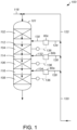
- a turbine is used in association with a quench stream, for example in a hydroprocessing reactor 100.
- hydroprocessing can refer to processing one or more hydrocarbons in the presence of hydrogen, and can include hydrotreating and/or hydrocracking.
- hydrocracking can refer to a process breaking or cracking bonds of at least one long-chain hydrocarbon in the presence of hydrogen and at least one catalyst into lower molecular weight hydrocarbons.
- hydrotreating can refer to a process including contacting a hydrocarbon feedstock with hydrogen gas in the presence of one or more suitable catalysts for the removal of heteroatoms, such as sulfur, nitrogen and metals from a hydrocarbon feedstock.
- suitable catalysts for the removal of heteroatoms, such as sulfur, nitrogen and metals from a hydrocarbon feedstock.
- hydrocarbons with double and triple bonds may be saturated, and aromatics may also be saturated, as some hydrotreating processes are specifically designed to saturate aromatics.
- a hydroprocessing reactor 100 that is used in accordance with the present invention is a multi-fixed bed vessel 101 which, as is known, comprises multiple catalyst beds 102, 104, 106, 108 that are separated from each other by pre-bed spaces 112, 114, 116 (also referred to as quench zones.
- each of the catalyst beds 102, 104, 106, 108 contain a hydrotreating catalyst.
- Hydrotreating catalysts are well known and typically comprise molybdenum (Mo), tungsten (W), cobalt (Co), and/or nickel (Ni) on a support comprised of ⁇ -alumina. The particular type of hydrotreating catalyst is not necessary for the understanding or practicing of the present invention.
- a feed stream 118 is introduced to the hydroprocessing reactor 100, preferably at the top of the vessel 101.
- a hydrogen-containing stream 120 is split in a plurality of streams into hydrogen rich streams 122, 124, 126, 128.
- the hydrogen-containing stream 120 is a hydrogen-rich stream.
- the term "rich” means an amount generally of at least 50%, and preferably 70%, by volume, of a compound or class of compounds in a stream.
- the hydrogen-containing stream 120 may contain recycle hydrogen from the hydroprocessing reactor 100, make-up hydrogen, or a combination of recycle hydrogen and make-up hydrogen.
- a first hydrogen rich stream 122 is combined with the feed stream 118, preferably upstream of any heat exchangers or furnaces.
- the remaining hydrogen rich streams 124, 126, 128 are used as quench streams 130, 132, 134 and injected into the pre-bed spaces 112, 114, 116 of the hydroprocessing reactor 100.
- turbines 60a, 60b, 60c are used. These turbines 60a, 60b, 60c are, for example, the turbine 60 shown in FIG. 2 (discussed below).
- the turbines 60a, 60b, 60c may each be in communication with a temperature sensor 136 configured to measure a temperature of one of the pre-bed spaces 112, 114, 116 and relay the temperature to the turbines 60a, 60b, 60c to adjust the flow of the respective quench streams 130, 132, 134.
- the hydrogen rich streams 124, 126, 128 will enter each of the turbines 60a, 60b, 60c and rotate turbine wheels therein (see, FIG. 2 ), thereby reducing the pressure and temperature of the hydrogen rich streams 124, 126, 128 and extracting energy from the hydrogen rich streams 124, 126, 128.
- the lower pressure and temperature quench streams 130, 132, 134 are injected into pre-bed spaces 112, 114, 116 of the reactor 100 and control the temperature of the catalyst beds 104, 106, 108 within the reactor 100.
- the flow rate of the stream coming from the turbine 60 can be adjusted to change a process condition in the hydroprocessing reactor 100.
- the flow rate of the quench streams 130, 132, 134 may be adjusted to change the temperature of the catalyst beds 102, 104, 106, 108 within the reactor 100. Accordingly, in changing these process conditions, it is contemplated that the changes are "slow control" in which the desired change occurs at a relatively slow pace.
- a response time to reach half way i.e., 50% of a difference
- a response time to reach half way is at least one second, or at least ten seconds, or at least 1 minute, or at least 10 minutes, or one hour or greater.
- the turbine provides a process that takes at least one second, or at least ten seconds, or at least 1 minute, or at least 10 minutes, or one hour or greater, for half of the change to completed.
- the turbine 60 includes a turbine wheel 62 with blades 64 configured to optionally transfer, or transmit, rotational movement, created by the flow of the stream passed through the turbine wheel 62, to an electrical generator 66.
- the electrical generator 66 generally includes a first winding 68, in communication with the turbine wheel 62 and a second winding 70 surrounding the first winding 68. As is known, the rotation of the first winding 68 relative to the second winding 70 will generate an electrical current.
- the electrical generator 66 could include a permanent magnet instead of one of the windings, 68, 70. Such electrical generators are known in the art.
- the turbine 60 may include a processor 72 configured to measure an amount of electricity generated by the turbine 60 and a transmitter 74 configured to transmit information associated with the amount of electricity generated by the turbine 60 to a computer 76 at a control center 78.
- the specific configuration of the turbine 60 is not essential to the practicing of the present invention provided that the turbine 60 allow for the desired pressure reduction and conversion of energy from the pressure reduction to electricity. Exemplary turbines and further details are described in U.S. Pat. Nos. 4,625,125 , 4,694,189 , 4,754,156 , and 9,203,969 .
- one of the hydrogen rich streams 124, 126, 128 from FIG. 1 will enter the turbine 60, via conduit 58, at an inlet and rotate the turbine wheel 62, thereby reducing the pressure and temperature of the hydrogen-rich stream and, preferably also extracting energy from same.
- the lower pressure stream 59 taken from the outlet of the turbine 60, is one of the quench streams 130, 132, 134 that is injected into the pre-bed spaces 112, 114, 116 of the reactor 100 and to control the temperature of the catalyst beds 104, 106, 108 within the reactor 100. (See, FIG. 1 ).
- the resistance of the turbine 60 is modulated, or adjusted.
- the turbine 60 may include a plurality of variable guide vanes disposed at the inlet of the turbine 60.
- the resistance of the turbine 60 is adjusted by changing an orientation of the variable guide vanes.
- a plurality of variable guide vanes may be disposed at the outlet of the turbine 60.
- the resistance of the turbine 60 is adjusted by changing an orientation of the variable guide vanes.
- the turbine 60 is a variable nozzle turbine. In such an embodiment, the resistance of the turbine 60 is adjusted by changing an orientation of the variable nozzle turbine.
- the vanes of the turbine the flow of the stream passing through the vanes will be adjusted (by either increasing the surface area of the vanes blocking or reducing the surface area of the vanes).
- the resistance of the turbine 60 is adjusted with the turbine wheel 62, for example, by exerting a force on the turbine wheel 62 increasing the energy needed to rotate the turbine wheel 62.
- the resistance of the turbine 60 is adjusted by applying an electromagnetic resistance to the rotor thereby varying the rotor torque on the turbine wheel 62. An example of this type of adjustment of the resistance is described in U.S. Pat. No. 8,404,918 .
- the process according to the present invention comprises directing a portion of a gaseous process stream through one or more variable-resistance turbines to control the flowrate of the gas process stream and, optionally, generate electric power therefrom; controlling a pressure and temperature of the gaseous process stream so that the gas exiting the power-recovery turbine remains in the gas phase; and measuring the flowrate or controlling the flowrate or both using a variable nozzle turbine, inlet variable guide vanes, or direct coupled variable electric load, to name a few, to vary the resistance to flow through the turbine.
- the resistance to rotation of the variable-resistance turbine can be varied by an external variable load electric circuit which is in a magnetic field from a magnet(s) that is rotating on the turbine.
- An algorithm in the device can also calculate the actual flow through the device by measuring the turbine RPMs and the load on the circuit.
- the resistance to rotation flow can also be varied by variable position inlet guide vanes.
- the power will be generated via power-recovery turbines with variable resistance to flow made possible by either guide vanes or variable load on the electrical power generation circuit.
- An algorithm to calculate actual flow using the guide vanes position, power output and RPMs can be used.
- the at least one steady state process condition that is adjusted may be a temperature, a pressure, such as a partial pressure, a level or reactant, chemical, catalyst, or feed, used in the chemical processing unit. If slow control response of the turbine is an issue then the use of the turbine is limited to slow responding or "loose" control point applications.
- a slow responding application is contemplated to have a response time to reach half way (i.e., 50% of a difference) between a new (or target) steady state condition (e.g., temperature, pressure, flow rate) from an original (or starting) steady state condition when the new (or target) condition differs from the original (or stating) condition of at least 10%, is of at least one second, or even greater, for example, ten seconds, at least one minute, at least ten minutes, or an hour or more, for half of the change to completed.
- a new (or target) steady state condition e.g., temperature, pressure, flow rate
- the processes of the present invention optimally generate electricity as a result of the rotation of the turbine wheel 62 within the turbine 60.
- Information associated with the generation of electricity may be utilized to control the chemical processing unit. Additionally, information associated with conditions outside of the turbine can be factored in and used to determine a power generated target based in part on the information associated with conditions outside of the turbine.
- Information associated with a throughput of the chemical processing unit can also be utilized to determine the power generated target value. In some processes, the throughput of the processing unit is maintained while the resistance of the turbine is adjusted. Multiple turbines may be utilized within the chemical processing unit and thus the process may include determining a total power generated value based upon the amount of electricity generated by the turbines, as well as displaying the total power generated value on the at least one display screen.
- the chemical processing units used in the present processes utilize a process control system.
- the process control system described in connection with the embodiments disclosed herein may be implemented or performed on the computer with a general purpose processor, a digital signal processor (DSP), an application specific integrated circuit (ASIC), a field programmable gate array (FPGA) or other programmable logic device, discrete gate or transistor logic, discrete hardware components, or any combination thereof designed to perform the functions described herein.
- a general-purpose processor may be a microprocessor, or, the processor may be any conventional processor, controller, microcontroller, or state machine.
- a processor may also be a combination of computing devices, e.g., a combination of a DSP and a microprocessor, two or more microprocessors, or any other combination of the foregoing.
- a software module may reside in RAM memory, flash memory, ROM memory, EPROM memory, EEPROM memory, registers, hard disk, a removable disk, a CD-ROM, or any other form of storage medium known in the art.
- An exemplary storage medium is in communication with the processor reading information from, and writing information to, the storage medium. This includes the storage medium being integral to or with the processor.
- the processor and the storage medium may reside in an ASIC.
- the ASIC may reside in a user terminal.
- the processor and the storage medium may reside as discrete components in a user terminal.
- processors and storage medium or memory are also typically in communication with hardware (e.g., ports, interfaces, antennas, amplifiers, signal processors, etc.) that allow for wired or wireless communication between different components, computers processors, or the like, such as between the input channel, a processor of the control logic, the output channels within the control system and the operator station in the control center.
- hardware e.g., ports, interfaces, antennas, amplifiers, signal processors, etc.
- the transmission of the data or information can be a wireless transmission (for example by Wi-Fi or Bluetooth) or a wired transmission (for example using an Ethernet RJ45 cable or an USB cable).
- a wireless transceiver for example a Wi-Fi transceiver
- the transmission can be performed automatically, at the request of the computers, in response to a request from a computer, or in other ways. Data can be pushed, pulled, fetched, etc., in any combination, or transmitted and received in any other manner.
- the process control system receives information relative to an amount of electricity generated by the turbines 60. It is contemplated that the turbine determines the amount of electricity it has generated, or alternatively, the process control system receiving the information determines the amount of electricity that has been generated. In either configuration, the amount of the electricity generated by the turbines 60 is displayed on at least one display screen 80 (for example in communication with the computer 76 in the control center 78). If the processing unit comprises a plurality of turbines 60, it is further contemplated that the processing control system receives information associated with the amount of electricity generated by each of the turbines 60. The processing control system determines a total power generated based upon the information associated with the each of the turbines 60 and displays that the total power generated. The total power generated may be displayed instead of or in conjunction with the display of the power generated by individual turbines 60.
- the processes according to the present invention provide for the various process conditions associated with the processing units to be adjusted into order to lower the energy added to the steam initially.
- the process control system receives information associated with the throughput of the processing unit, and determines a target power generated value for the turbines 60, since the electricity represents energy that is typically added to the overall processing unit. The determination of the target power generated value may be done when the electricity is at or near a predetermined level.
- the process control system will analyze one or more changes to the various process conditions associated with the processing unit to lower the amount of energy recovered by the turbines 60.
- the process conditions are adjusted without adjusting the throughput of the processing unit. This allows for the processing unit to have the same output, but with a lower operating input.
- the process control software may calculate and display the difference between the target power generated value and the total power generated on the at least one display screen 80.
- the turbine By using modulating the resistance of the turbine to adjust one or more steady state process conditions, the turbine allows for a “slow control" over the adjustment of the steady state process condition.
Landscapes
- Engineering & Computer Science (AREA)
- Mechanical Engineering (AREA)
- General Engineering & Computer Science (AREA)
- Chemical & Material Sciences (AREA)
- Combustion & Propulsion (AREA)
- Oil, Petroleum & Natural Gas (AREA)
- Chemical Kinetics & Catalysis (AREA)
- General Chemical & Material Sciences (AREA)
- Organic Chemistry (AREA)
- Control Of Turbines (AREA)
Claims (8)
- Verfahren zum Steuern mindestens eines stationären Zustands eines Hydroprozessierungsreaktors (100), wobei das Verfahren umfasst:Leiten eines Fluids in einem Quenchstrom (130, 132, 134) des Hydroprozessierungsreaktors (100) durch eine Turbine (60, 60a, 60b, 60c), um dem Fluid eine Strömung bereitzustellen, die mit mindestens einem Zustand des Hydroprozessierungsreaktors (100) assoziiert ist;Drehen eines Turbinenrads (62) innerhalb der Turbine (60, 60a, 60b, 60c), wobei das Turbinenrad (62) so konfiguriert ist, dass es eine Drehbewegung auf einen elektrischen Generator überträgt;Erzeugen von Elektrizität mit der Turbine (60, 60a, 60b, 60c); undModulieren eines Widerstands der Turbine (60, 60a, 60b, 60c), um die Strömung des Fluids im Quenchstrom (130, 132, 134) durch die Turbine (60, 60a, 60b, 60c) einzustellen, wobei eine Reaktionszeit von mindestens einem stationären Zustand auf einen neuen stationären Zustand von mindestens 10 % Differenz mindestens eine Sekunde beträgt, um 50 % der Differenz zwischen dem mindestens einen stationären Zustand und dem neuen stationären Zustand nach Modulation des Widerstands der Turbine (60, 60a, 60b, 60c) zu erreichen;
wobeider mindestens eine stationäre Prozesszustand des Hydroprozessierungsreaktors (100) eine Temperatur umfasst. - Verfahren nach Anspruch 1, wobei eine Strömungsrate des Quenchstroms (130, 132, 134) eingestellt wird, um eine Temperatur eines Katalysatorbetts (102, 104, 106, 108) innerhalb des Hydroprozessierungsreaktors (100) zu verändern.
- Verfahren nach Anspruch 1, wobei die Turbine (60, 60a, 60b, 60c) einen Einlass aufweist und wobei eine Vielzahl von variablen Leitschaufeln am Einlass der Turbine angeordnet ist und wobei der Widerstand der Turbine (60, 60a, 60b, 60c) durch Ändern einer Ausrichtung der variablen Leitschaufeln moduliert wird.
- Verfahren nach Anspruch 1, wobei die Turbine (60, 60a, 60b, 60c) einen Auslass aufweist und wobei eine Vielzahl von variablen Leitschaufeln am Auslass der Turbine angeordnet ist und wobei der Widerstand der Turbine (60, 60a, 60b, 60c) durch Ändern einer Ausrichtung der variablen Leitschaufeln moduliert wird.
- Verfahren nach Anspruch 1, wobei die Turbine (60, 60a, 60b, 60c) eine Turbine mit variabler Düse umfasst und wobei der Widerstand der Turbine (60, 60a, 60b, 60c) durch Ändern einer Ausrichtung der Turbine mit variabler Düse moduliert wird.
- Verfahren nach Anspruch 1, wobei der Widerstand der Turbine (60, 60a, 60b, 60c) mit dem Turbinenrad (62) eingestellt wird.
- Verfahren nach Anspruch 1, wobei der Widerstand der Turbine (60, 60a, 60b, 60c) mit einem elektromagnetischen Widerstand eingestellt wird, der an einen Rotor angelegt wird, wodurch ein Rotordrehmoment variiert wird, wobei der Rotor in Verbindung mit dem Turbinenrad (62) steht.
- Verfahren nach Anspruch 1, wobei der mindestens eine stationäre Prozesszustand der chemischen Verarbeitungseinheit (100) ferner einen Druck umfasst.
Applications Claiming Priority (2)
| Application Number | Priority Date | Filing Date | Title |
|---|---|---|---|
| US15/923,997 US11131218B2 (en) | 2018-03-16 | 2018-03-16 | Processes for adjusting at least one process condition of a chemical processing unit with a turbine |
| PCT/US2019/022449 WO2019178467A1 (en) | 2018-03-16 | 2019-03-15 | Processes for adjusting condition of a chemical processing unit with a turbine. |
Publications (3)
| Publication Number | Publication Date |
|---|---|
| EP3765718A1 EP3765718A1 (de) | 2021-01-20 |
| EP3765718A4 EP3765718A4 (de) | 2021-12-01 |
| EP3765718B1 true EP3765718B1 (de) | 2023-11-08 |
Family
ID=67905256
Family Applications (1)
| Application Number | Title | Priority Date | Filing Date |
|---|---|---|---|
| EP19767299.1A Active EP3765718B1 (de) | 2018-03-16 | 2019-03-15 | Verfahren zur einstellung des zustandes einer chemischen verarbeitungseinheit mit einer turbine |
Country Status (4)
| Country | Link |
|---|---|
| US (1) | US11131218B2 (de) |
| EP (1) | EP3765718B1 (de) |
| JP (1) | JP7106666B2 (de) |
| WO (1) | WO2019178467A1 (de) |
Family Cites Families (56)
| Publication number | Priority date | Publication date | Assignee | Title |
|---|---|---|---|---|
| US4455614A (en) | 1973-09-21 | 1984-06-19 | Westinghouse Electric Corp. | Gas turbine and steam turbine combined cycle electric power generating plant having a coordinated and hybridized control system and an improved factory based method for making and testing combined cycle and other power plants and control systems therefor |
| FR2414162A1 (fr) | 1978-01-09 | 1979-08-03 | Lenz Karl | Procede et agencement pour commander, surveiller et mesurer le debit d'un clapet de passage de fluide |
| US4285481A (en) | 1979-06-04 | 1981-08-25 | Biscomb Lloyd I | Multiple wind turbine tethered airfoil wind energy conversion system |
| EP0552039A1 (de) | 1992-01-17 | 1993-07-21 | Gec-Marconi Limited | Senderabstimmung |
| US5384489A (en) | 1994-02-07 | 1995-01-24 | Bellac; Alphonse H. | Wind-powered electricity generating system including wind energy storage |
| US6009711A (en) | 1997-08-14 | 2000-01-04 | Ormat Industries Ltd. | Apparatus and method for producing power using geothermal fluid |
| US6681155B1 (en) | 1998-08-31 | 2004-01-20 | Mitsubishi Chemical Corporation | Optimizing control method and optimizing control system for power plant |
| AU755360B2 (en) | 1998-12-31 | 2002-12-12 | Shell Internationale Research Maatschappij B.V. | Method for removing condensables from a natural gas stream, at a wellhead, downstream of the wellhead choke |
| US6265453B1 (en) | 1999-07-01 | 2001-07-24 | Syntroleum Corporation | Hydrocarbon conversion system with enhanced combustor and method |
| US6261055B1 (en) | 1999-08-03 | 2001-07-17 | Jerzy A. Owczarek | Exhaust flow diffuser for a steam turbine |
| US6354084B1 (en) | 1999-08-20 | 2002-03-12 | Cummins Engine Company, Inc. | Exhaust gas recirculation system for a turbocharged internal combustion engine |
| DE102009031557A1 (de) | 2009-03-02 | 2010-09-09 | Sms Siemag Ag | Energierückgewinnung in Warmbandstraßen durch Umwandlung der Kühlwärme der Stranggießanlage sowie der Restwärme von Brammen und Coils in elektrische Energie oder sonstige Nutzung der aufgefangenen Prozesswärme |
| US6898540B2 (en) | 2002-11-12 | 2005-05-24 | General Electric Company | System and method for displaying real-time turbine corrected output and heat rate |
| US6938425B2 (en) | 2003-08-11 | 2005-09-06 | Siemens Westinghouse Power Corporation | System and method for controlling water injection in a turbine engine |
| WO2007025387A1 (en) | 2005-09-02 | 2007-03-08 | John Christopher Burtch | Apparatus for production of hydrogen gas using wind and wave action |
| US7757493B2 (en) | 2006-03-07 | 2010-07-20 | Uop Llc | Fluid catalytic cracking steam pressure letdown power recovery system and process |
| CA2655973C (en) | 2006-06-23 | 2013-08-13 | Saudi Arabian Oil Company | System, method, and program product for targeting and optimal driving force distribution in energy recovery systems |
| US8688405B2 (en) | 2007-06-15 | 2014-04-01 | Shell Oil Company | Remote monitoring systems and methods |
| US20090125152A1 (en) | 2007-11-09 | 2009-05-14 | Markron Technologies, Llc | Method of measurement, control, and regulation for the solar thermal hybridization of a fossil fired rankine cycle |
| EP2083154A1 (de) * | 2008-01-23 | 2009-07-29 | Technische Universiteit Eindhoven | Lufteinlasssystem für Verbrennungsmotoren, Klimaanlage und Verbrennungsmotor mit dem Lufteinlasssystem |
| CA2726984C (en) | 2008-06-06 | 2014-12-30 | Aramco Services Company | System, program product, and related methods for global targeting of process utilities under varying conditions |
| EP2301886A1 (de) | 2009-09-03 | 2011-03-30 | Ammonia Casale S.A. | Abwärmerückgewinnung in einem chemischen Prozess und Anlage, insbesondere zur Synthese von Ammoniak |
| US8404918B2 (en) * | 2009-09-28 | 2013-03-26 | Uop Llc | Energy efficiency in adsorptive separation |
| WO2011053925A2 (en) | 2009-10-30 | 2011-05-05 | Qgen Ltd. | Control and solar power improvements of a concentrated solar power-enabled power plant |
| US20120245754A1 (en) | 2009-12-05 | 2012-09-27 | Jens Mehnert | Method and apparatus for analysis of energy input during operation of a production system |
| US8967590B2 (en) | 2010-03-02 | 2015-03-03 | Westlock Controls Corporation | Micro-power generator for valve control applications |
| FR2966814B1 (fr) | 2010-10-28 | 2016-01-01 | IFP Energies Nouvelles | Procede de production d'hydrogene par vaporeformage d'une coupe petroliere avec production de vapeur optimisee. |
| US20120227440A1 (en) | 2011-03-10 | 2012-09-13 | Alstom Technology Ltd. | System And Process For The Physical Absorption of Carbon Dioxide From a Flue Gas Stream |
| US9222410B2 (en) | 2011-04-13 | 2015-12-29 | General Electric Company | Power plant |
| US8911616B2 (en) * | 2011-04-26 | 2014-12-16 | Uop Llc | Hydrotreating process and controlling a temperature thereof |
| CA2780451A1 (en) | 2011-06-21 | 2012-12-21 | Genalta Power, Inc. | Variable speed power generation from industrial fluid energy sources |
| US9085499B2 (en) | 2011-11-09 | 2015-07-21 | Uop Llc | Energy efficiency in adsorptive separation |
| WO2013116861A1 (en) | 2012-02-02 | 2013-08-08 | Electratherm, Inc. | Improved heat utilization in orc systems |
| GB2499991A (en) | 2012-03-05 | 2013-09-11 | Solaredge Technologies Ltd | DC link circuit for photovoltaic array |
| JP2016056808A (ja) | 2013-01-29 | 2016-04-21 | 日立建機株式会社 | 作業機械の圧油エネルギ回収装置 |
| JP6010489B2 (ja) | 2013-03-12 | 2016-10-19 | 三菱日立パワーシステムズ株式会社 | 熱電可変型コジェネレーションシステム |
| US9127218B2 (en) * | 2013-03-26 | 2015-09-08 | Uop Llc | Hydroprocessing and apparatus relating thereto |
| US8763625B1 (en) | 2013-04-12 | 2014-07-01 | John T. Carter | Siphon pump technology and apparatuses |
| JP5790952B2 (ja) | 2013-04-23 | 2015-10-07 | 横河電機株式会社 | 生産エネルギー管理システムおよびコンピュータプログラム |
| WO2014178079A2 (en) | 2013-04-26 | 2014-11-06 | Eesavyasa Technologies Pvt. Ltd | Led lighting systems using compressed air based power generation and a method thereof |
| CN104463341B (zh) | 2013-09-25 | 2017-10-27 | 北京宜能高科科技有限公司 | 图表化的蒸汽动力系统分析优化方法和装置 |
| US9764272B2 (en) | 2013-10-28 | 2017-09-19 | Energy Recovery, Inc. | Systems and methods for utilizing turbine systems within gas processing systems |
| US20160252015A1 (en) | 2013-11-27 | 2016-09-01 | Hitachi, Ltd. | Gas Turbine Corresponding to Renewable Energy and Control Method Therefor |
| RU2570131C2 (ru) | 2014-04-09 | 2015-12-10 | Федеральное государственное бюджетное образовательное учреждение высшего профессионального образования "Казанский государственный энергетический университет" (ФГБОУ ВПО "КГЭУ") | Способ работы тепловой электрической станции |
| AU2015284297B2 (en) | 2014-06-30 | 2020-02-20 | Robert Kremer | An apparatus, system and method for utilizing thermal energy |
| JP6368611B2 (ja) * | 2014-10-03 | 2018-08-01 | 三菱日立パワーシステムズ株式会社 | ガスタービン、コンバインドサイクルプラント、ガスタービンの起動方法 |
| US20160141878A1 (en) | 2014-11-05 | 2016-05-19 | John Anton Johansen | Dc appliance system |
| US10088507B2 (en) | 2014-12-03 | 2018-10-02 | Saudi Arabian Oil Company | Energy performance metric in hydrocarbon-producing facilities |
| US11060032B2 (en) | 2015-01-02 | 2021-07-13 | Suncoke Technology And Development Llc | Integrated coke plant automation and optimization using advanced control and optimization techniques |
| WO2016177376A1 (en) | 2015-05-06 | 2016-11-10 | Vestas Wind Systems A/S | Wind turbine power generation system |
| US9803509B2 (en) | 2015-08-24 | 2017-10-31 | Saudi Arabian Oil Company | Power generation from waste heat in integrated crude oil refining and aromatics facilities |
| WO2018002819A1 (en) * | 2016-06-27 | 2018-01-04 | University Of Pretoria | A method and system for measuring rotor blade tip deflection using blade tip timing (btt) |
| CN206538206U (zh) | 2016-11-29 | 2017-10-03 | 江苏悦达家纺有限公司 | 一种可优化水质的热回收装置 |
| US10690010B2 (en) * | 2018-03-16 | 2020-06-23 | Uop Llc | Steam reboiler with turbine |
| GB201807771D0 (en) * | 2018-05-14 | 2018-06-27 | Rolls Royce Plc | Hybrid electric aircraft propulsion system |
| US10774677B2 (en) * | 2018-05-29 | 2020-09-15 | Ford Global Technologies, Llc | Systems and methods for a variable inlet compressor |
-
2018
- 2018-03-16 US US15/923,997 patent/US11131218B2/en active Active
-
2019
- 2019-03-15 WO PCT/US2019/022449 patent/WO2019178467A1/en not_active Ceased
- 2019-03-15 EP EP19767299.1A patent/EP3765718B1/de active Active
- 2019-03-15 JP JP2020547110A patent/JP7106666B2/ja active Active
Also Published As
| Publication number | Publication date |
|---|---|
| WO2019178467A1 (en) | 2019-09-19 |
| JP7106666B2 (ja) | 2022-07-26 |
| JP2021516309A (ja) | 2021-07-01 |
| EP3765718A1 (de) | 2021-01-20 |
| US20190284950A1 (en) | 2019-09-19 |
| EP3765718A4 (de) | 2021-12-01 |
| US11131218B2 (en) | 2021-09-28 |
Similar Documents
| Publication | Publication Date | Title |
|---|---|---|
| EP3766168B1 (de) | Prozessverbesserung durch hinzufügung einer energierückgewinnungsturbinenanlage in bestehende prozesse | |
| EP3765583B1 (de) | Hydroverarbeitungseinheit mit energierückgewinnungsturbinen | |
| US10690010B2 (en) | Steam reboiler with turbine | |
| US10753235B2 (en) | Use of recovered power in a process | |
| US11713697B2 (en) | Energy-recovery turbines for gas streams | |
| EP3765718B1 (de) | Verfahren zur einstellung des zustandes einer chemischen verarbeitungseinheit mit einer turbine | |
| JP2013162563A (ja) | 電力需給制御装置および電力需給制御方法 | |
| WO2019178459A1 (en) | Turbine with supersonic separation | |
| EP3765717B1 (de) | Konsolidierung und verwendung von energie aus einer turbine in einer prozesseinheit | |
| JP5539416B2 (ja) | 水車発電機の制御装置及び制御方法並びに水力発電システム | |
| US20200003082A1 (en) | Energy-recovery turbines for gas streams | |
| JP2010031796A (ja) | ガス供給装置 |
Legal Events
| Date | Code | Title | Description |
|---|---|---|---|
| STAA | Information on the status of an ep patent application or granted ep patent |
Free format text: STATUS: THE INTERNATIONAL PUBLICATION HAS BEEN MADE |
|
| PUAI | Public reference made under article 153(3) epc to a published international application that has entered the european phase |
Free format text: ORIGINAL CODE: 0009012 |
|
| STAA | Information on the status of an ep patent application or granted ep patent |
Free format text: STATUS: REQUEST FOR EXAMINATION WAS MADE |
|
| 17P | Request for examination filed |
Effective date: 20200915 |
|
| AK | Designated contracting states |
Kind code of ref document: A1 Designated state(s): AL AT BE BG CH CY CZ DE DK EE ES FI FR GB GR HR HU IE IS IT LI LT LU LV MC MK MT NL NO PL PT RO RS SE SI SK SM TR |
|
| AX | Request for extension of the european patent |
Extension state: BA ME |
|
| DAV | Request for validation of the european patent (deleted) | ||
| DAX | Request for extension of the european patent (deleted) | ||
| REG | Reference to a national code |
Ref country code: DE Ref legal event code: R079 Free format text: PREVIOUS MAIN CLASS: F01D0017100000 Ipc: F01D0017160000 Ref country code: DE Ref legal event code: R079 Ref document number: 602019041106 Country of ref document: DE Free format text: PREVIOUS MAIN CLASS: F01D0017100000 Ipc: F01D0017160000 |
|
| A4 | Supplementary search report drawn up and despatched |
Effective date: 20211028 |
|
| RIC1 | Information provided on ipc code assigned before grant |
Ipc: C10G 11/18 20060101ALI20211022BHEP Ipc: C10G 49/26 20060101ALI20211022BHEP Ipc: F01D 15/10 20060101ALI20211022BHEP Ipc: F01D 17/16 20060101AFI20211022BHEP |
|
| P01 | Opt-out of the competence of the unified patent court (upc) registered |
Effective date: 20230421 |
|
| GRAP | Despatch of communication of intention to grant a patent |
Free format text: ORIGINAL CODE: EPIDOSNIGR1 |
|
| STAA | Information on the status of an ep patent application or granted ep patent |
Free format text: STATUS: GRANT OF PATENT IS INTENDED |
|
| INTG | Intention to grant announced |
Effective date: 20230616 |
|
| GRAS | Grant fee paid |
Free format text: ORIGINAL CODE: EPIDOSNIGR3 |
|
| GRAA | (expected) grant |
Free format text: ORIGINAL CODE: 0009210 |
|
| STAA | Information on the status of an ep patent application or granted ep patent |
Free format text: STATUS: THE PATENT HAS BEEN GRANTED |
|
| AK | Designated contracting states |
Kind code of ref document: B1 Designated state(s): AL AT BE BG CH CY CZ DE DK EE ES FI FR GB GR HR HU IE IS IT LI LT LU LV MC MK MT NL NO PL PT RO RS SE SI SK SM TR |
|
| REG | Reference to a national code |
Ref country code: GB Ref legal event code: FG4D |
|
| REG | Reference to a national code |
Ref country code: CH Ref legal event code: EP |
|
| REG | Reference to a national code |
Ref country code: DE Ref legal event code: R096 Ref document number: 602019041106 Country of ref document: DE |
|
| REG | Reference to a national code |
Ref country code: IE Ref legal event code: FG4D |
|
| REG | Reference to a national code |
Ref country code: LT Ref legal event code: MG9D |
|
| REG | Reference to a national code |
Ref country code: NL Ref legal event code: MP Effective date: 20231108 |
|
| PG25 | Lapsed in a contracting state [announced via postgrant information from national office to epo] |
Ref country code: GR Free format text: LAPSE BECAUSE OF FAILURE TO SUBMIT A TRANSLATION OF THE DESCRIPTION OR TO PAY THE FEE WITHIN THE PRESCRIBED TIME-LIMIT Effective date: 20240209 |
|
| PG25 | Lapsed in a contracting state [announced via postgrant information from national office to epo] |
Ref country code: IS Free format text: LAPSE BECAUSE OF FAILURE TO SUBMIT A TRANSLATION OF THE DESCRIPTION OR TO PAY THE FEE WITHIN THE PRESCRIBED TIME-LIMIT Effective date: 20240308 |
|
| PG25 | Lapsed in a contracting state [announced via postgrant information from national office to epo] |
Ref country code: LT Free format text: LAPSE BECAUSE OF FAILURE TO SUBMIT A TRANSLATION OF THE DESCRIPTION OR TO PAY THE FEE WITHIN THE PRESCRIBED TIME-LIMIT Effective date: 20231108 |
|
| REG | Reference to a national code |
Ref country code: AT Ref legal event code: MK05 Ref document number: 1629785 Country of ref document: AT Kind code of ref document: T Effective date: 20231108 |
|
| PG25 | Lapsed in a contracting state [announced via postgrant information from national office to epo] |
Ref country code: NL Free format text: LAPSE BECAUSE OF FAILURE TO SUBMIT A TRANSLATION OF THE DESCRIPTION OR TO PAY THE FEE WITHIN THE PRESCRIBED TIME-LIMIT Effective date: 20231108 |
|
| PG25 | Lapsed in a contracting state [announced via postgrant information from national office to epo] |
Ref country code: AT Free format text: LAPSE BECAUSE OF FAILURE TO SUBMIT A TRANSLATION OF THE DESCRIPTION OR TO PAY THE FEE WITHIN THE PRESCRIBED TIME-LIMIT Effective date: 20231108 |
|
| PG25 | Lapsed in a contracting state [announced via postgrant information from national office to epo] |
Ref country code: ES Free format text: LAPSE BECAUSE OF FAILURE TO SUBMIT A TRANSLATION OF THE DESCRIPTION OR TO PAY THE FEE WITHIN THE PRESCRIBED TIME-LIMIT Effective date: 20231108 |
|
| PG25 | Lapsed in a contracting state [announced via postgrant information from national office to epo] |
Ref country code: NL Free format text: LAPSE BECAUSE OF FAILURE TO SUBMIT A TRANSLATION OF THE DESCRIPTION OR TO PAY THE FEE WITHIN THE PRESCRIBED TIME-LIMIT Effective date: 20231108 Ref country code: LT Free format text: LAPSE BECAUSE OF FAILURE TO SUBMIT A TRANSLATION OF THE DESCRIPTION OR TO PAY THE FEE WITHIN THE PRESCRIBED TIME-LIMIT Effective date: 20231108 Ref country code: IS Free format text: LAPSE BECAUSE OF FAILURE TO SUBMIT A TRANSLATION OF THE DESCRIPTION OR TO PAY THE FEE WITHIN THE PRESCRIBED TIME-LIMIT Effective date: 20240308 Ref country code: GR Free format text: LAPSE BECAUSE OF FAILURE TO SUBMIT A TRANSLATION OF THE DESCRIPTION OR TO PAY THE FEE WITHIN THE PRESCRIBED TIME-LIMIT Effective date: 20240209 Ref country code: ES Free format text: LAPSE BECAUSE OF FAILURE TO SUBMIT A TRANSLATION OF THE DESCRIPTION OR TO PAY THE FEE WITHIN THE PRESCRIBED TIME-LIMIT Effective date: 20231108 Ref country code: BG Free format text: LAPSE BECAUSE OF FAILURE TO SUBMIT A TRANSLATION OF THE DESCRIPTION OR TO PAY THE FEE WITHIN THE PRESCRIBED TIME-LIMIT Effective date: 20240208 Ref country code: AT Free format text: LAPSE BECAUSE OF FAILURE TO SUBMIT A TRANSLATION OF THE DESCRIPTION OR TO PAY THE FEE WITHIN THE PRESCRIBED TIME-LIMIT Effective date: 20231108 Ref country code: PT Free format text: LAPSE BECAUSE OF FAILURE TO SUBMIT A TRANSLATION OF THE DESCRIPTION OR TO PAY THE FEE WITHIN THE PRESCRIBED TIME-LIMIT Effective date: 20240308 |
|
| PG25 | Lapsed in a contracting state [announced via postgrant information from national office to epo] |
Ref country code: SE Free format text: LAPSE BECAUSE OF FAILURE TO SUBMIT A TRANSLATION OF THE DESCRIPTION OR TO PAY THE FEE WITHIN THE PRESCRIBED TIME-LIMIT Effective date: 20231108 Ref country code: RS Free format text: LAPSE BECAUSE OF FAILURE TO SUBMIT A TRANSLATION OF THE DESCRIPTION OR TO PAY THE FEE WITHIN THE PRESCRIBED TIME-LIMIT Effective date: 20231108 Ref country code: PL Free format text: LAPSE BECAUSE OF FAILURE TO SUBMIT A TRANSLATION OF THE DESCRIPTION OR TO PAY THE FEE WITHIN THE PRESCRIBED TIME-LIMIT Effective date: 20231108 Ref country code: NO Free format text: LAPSE BECAUSE OF FAILURE TO SUBMIT A TRANSLATION OF THE DESCRIPTION OR TO PAY THE FEE WITHIN THE PRESCRIBED TIME-LIMIT Effective date: 20240208 Ref country code: LV Free format text: LAPSE BECAUSE OF FAILURE TO SUBMIT A TRANSLATION OF THE DESCRIPTION OR TO PAY THE FEE WITHIN THE PRESCRIBED TIME-LIMIT Effective date: 20231108 Ref country code: HR Free format text: LAPSE BECAUSE OF FAILURE TO SUBMIT A TRANSLATION OF THE DESCRIPTION OR TO PAY THE FEE WITHIN THE PRESCRIBED TIME-LIMIT Effective date: 20231108 |
|
| PG25 | Lapsed in a contracting state [announced via postgrant information from national office to epo] |
Ref country code: DK Free format text: LAPSE BECAUSE OF FAILURE TO SUBMIT A TRANSLATION OF THE DESCRIPTION OR TO PAY THE FEE WITHIN THE PRESCRIBED TIME-LIMIT Effective date: 20231108 |
|
| PG25 | Lapsed in a contracting state [announced via postgrant information from national office to epo] |
Ref country code: CZ Free format text: LAPSE BECAUSE OF FAILURE TO SUBMIT A TRANSLATION OF THE DESCRIPTION OR TO PAY THE FEE WITHIN THE PRESCRIBED TIME-LIMIT Effective date: 20231108 |
|
| PG25 | Lapsed in a contracting state [announced via postgrant information from national office to epo] |
Ref country code: SK Free format text: LAPSE BECAUSE OF FAILURE TO SUBMIT A TRANSLATION OF THE DESCRIPTION OR TO PAY THE FEE WITHIN THE PRESCRIBED TIME-LIMIT Effective date: 20231108 |
|
| PG25 | Lapsed in a contracting state [announced via postgrant information from national office to epo] |
Ref country code: SM Free format text: LAPSE BECAUSE OF FAILURE TO SUBMIT A TRANSLATION OF THE DESCRIPTION OR TO PAY THE FEE WITHIN THE PRESCRIBED TIME-LIMIT Effective date: 20231108 Ref country code: SK Free format text: LAPSE BECAUSE OF FAILURE TO SUBMIT A TRANSLATION OF THE DESCRIPTION OR TO PAY THE FEE WITHIN THE PRESCRIBED TIME-LIMIT Effective date: 20231108 Ref country code: RO Free format text: LAPSE BECAUSE OF FAILURE TO SUBMIT A TRANSLATION OF THE DESCRIPTION OR TO PAY THE FEE WITHIN THE PRESCRIBED TIME-LIMIT Effective date: 20231108 Ref country code: EE Free format text: LAPSE BECAUSE OF FAILURE TO SUBMIT A TRANSLATION OF THE DESCRIPTION OR TO PAY THE FEE WITHIN THE PRESCRIBED TIME-LIMIT Effective date: 20231108 Ref country code: DK Free format text: LAPSE BECAUSE OF FAILURE TO SUBMIT A TRANSLATION OF THE DESCRIPTION OR TO PAY THE FEE WITHIN THE PRESCRIBED TIME-LIMIT Effective date: 20231108 Ref country code: CZ Free format text: LAPSE BECAUSE OF FAILURE TO SUBMIT A TRANSLATION OF THE DESCRIPTION OR TO PAY THE FEE WITHIN THE PRESCRIBED TIME-LIMIT Effective date: 20231108 |
|
| REG | Reference to a national code |
Ref country code: DE Ref legal event code: R097 Ref document number: 602019041106 Country of ref document: DE |
|
| PLBE | No opposition filed within time limit |
Free format text: ORIGINAL CODE: 0009261 |
|
| STAA | Information on the status of an ep patent application or granted ep patent |
Free format text: STATUS: NO OPPOSITION FILED WITHIN TIME LIMIT |
|
| 26N | No opposition filed |
Effective date: 20240809 |
|
| PG25 | Lapsed in a contracting state [announced via postgrant information from national office to epo] |
Ref country code: SI Free format text: LAPSE BECAUSE OF FAILURE TO SUBMIT A TRANSLATION OF THE DESCRIPTION OR TO PAY THE FEE WITHIN THE PRESCRIBED TIME-LIMIT Effective date: 20231108 |
|
| PG25 | Lapsed in a contracting state [announced via postgrant information from national office to epo] |
Ref country code: SI Free format text: LAPSE BECAUSE OF FAILURE TO SUBMIT A TRANSLATION OF THE DESCRIPTION OR TO PAY THE FEE WITHIN THE PRESCRIBED TIME-LIMIT Effective date: 20231108 |
|
| REG | Reference to a national code |
Ref country code: CH Ref legal event code: PL |
|
| PG25 | Lapsed in a contracting state [announced via postgrant information from national office to epo] |
Ref country code: LU Free format text: LAPSE BECAUSE OF NON-PAYMENT OF DUE FEES Effective date: 20240315 |
|
| PG25 | Lapsed in a contracting state [announced via postgrant information from national office to epo] |
Ref country code: MC Free format text: LAPSE BECAUSE OF FAILURE TO SUBMIT A TRANSLATION OF THE DESCRIPTION OR TO PAY THE FEE WITHIN THE PRESCRIBED TIME-LIMIT Effective date: 20231108 |
|
| GBPC | Gb: european patent ceased through non-payment of renewal fee |
Effective date: 20240315 |
|
| PG25 | Lapsed in a contracting state [announced via postgrant information from national office to epo] |
Ref country code: MC Free format text: LAPSE BECAUSE OF FAILURE TO SUBMIT A TRANSLATION OF THE DESCRIPTION OR TO PAY THE FEE WITHIN THE PRESCRIBED TIME-LIMIT Effective date: 20231108 Ref country code: LU Free format text: LAPSE BECAUSE OF NON-PAYMENT OF DUE FEES Effective date: 20240315 |
|
| REG | Reference to a national code |
Ref country code: BE Ref legal event code: MM Effective date: 20240331 |
|
| PG25 | Lapsed in a contracting state [announced via postgrant information from national office to epo] |
Ref country code: BE Free format text: LAPSE BECAUSE OF NON-PAYMENT OF DUE FEES Effective date: 20240331 |
|
| PG25 | Lapsed in a contracting state [announced via postgrant information from national office to epo] |
Ref country code: GB Free format text: LAPSE BECAUSE OF NON-PAYMENT OF DUE FEES Effective date: 20240315 |
|
| PG25 | Lapsed in a contracting state [announced via postgrant information from national office to epo] |
Ref country code: IE Free format text: LAPSE BECAUSE OF NON-PAYMENT OF DUE FEES Effective date: 20240315 |
|
| PG25 | Lapsed in a contracting state [announced via postgrant information from national office to epo] |
Ref country code: IE Free format text: LAPSE BECAUSE OF NON-PAYMENT OF DUE FEES Effective date: 20240315 Ref country code: GB Free format text: LAPSE BECAUSE OF NON-PAYMENT OF DUE FEES Effective date: 20240315 Ref country code: BE Free format text: LAPSE BECAUSE OF NON-PAYMENT OF DUE FEES Effective date: 20240331 Ref country code: CH Free format text: LAPSE BECAUSE OF NON-PAYMENT OF DUE FEES Effective date: 20240331 |
|
| PG25 | Lapsed in a contracting state [announced via postgrant information from national office to epo] |
Ref country code: CY Free format text: LAPSE BECAUSE OF FAILURE TO SUBMIT A TRANSLATION OF THE DESCRIPTION OR TO PAY THE FEE WITHIN THE PRESCRIBED TIME-LIMIT; INVALID AB INITIO Effective date: 20190315 |
|
| PG25 | Lapsed in a contracting state [announced via postgrant information from national office to epo] |
Ref country code: HU Free format text: LAPSE BECAUSE OF FAILURE TO SUBMIT A TRANSLATION OF THE DESCRIPTION OR TO PAY THE FEE WITHIN THE PRESCRIBED TIME-LIMIT; INVALID AB INITIO Effective date: 20190315 |
|
| PG25 | Lapsed in a contracting state [announced via postgrant information from national office to epo] |
Ref country code: FI Free format text: LAPSE BECAUSE OF FAILURE TO SUBMIT A TRANSLATION OF THE DESCRIPTION OR TO PAY THE FEE WITHIN THE PRESCRIBED TIME-LIMIT Effective date: 20231108 |
|
| PG25 | Lapsed in a contracting state [announced via postgrant information from national office to epo] |
Ref country code: TR Free format text: LAPSE BECAUSE OF FAILURE TO SUBMIT A TRANSLATION OF THE DESCRIPTION OR TO PAY THE FEE WITHIN THE PRESCRIBED TIME-LIMIT Effective date: 20231108 |
|
| PGFP | Annual fee paid to national office [announced via postgrant information from national office to epo] |
Ref country code: DE Payment date: 20260320 Year of fee payment: 8 |
|
| PGFP | Annual fee paid to national office [announced via postgrant information from national office to epo] |
Ref country code: IT Payment date: 20260320 Year of fee payment: 8 |
|
| PGFP | Annual fee paid to national office [announced via postgrant information from national office to epo] |
Ref country code: FR Payment date: 20260323 Year of fee payment: 8 |