EP3765737B1 - Gondel-montierbares liftsystem für eine windturbine - Google Patents
Gondel-montierbares liftsystem für eine windturbine Download PDFInfo
- Publication number
- EP3765737B1 EP3765737B1 EP19800561.3A EP19800561A EP3765737B1 EP 3765737 B1 EP3765737 B1 EP 3765737B1 EP 19800561 A EP19800561 A EP 19800561A EP 3765737 B1 EP3765737 B1 EP 3765737B1
- Authority
- EP
- European Patent Office
- Prior art keywords
- lift system
- boom
- nacelle
- trolley
- mountable
- Prior art date
- Legal status (The legal status is an assumption and is not a legal conclusion. Google has not performed a legal analysis and makes no representation as to the accuracy of the status listed.)
- Active
Links
Images


Classifications
-
- B—PERFORMING OPERATIONS; TRANSPORTING
- B66—HOISTING; LIFTING; HAULING
- B66C—CRANES; LOAD-ENGAGING ELEMENTS OR DEVICES FOR CRANES, CAPSTANS, WINCHES, OR TACKLES
- B66C23/00—Cranes comprising essentially a beam, boom, or triangular structure acting as a cantilever and mounted for translatory of swinging movements in vertical or horizontal planes or a combination of such movements, e.g. jib-cranes, derricks, tower cranes
- B66C23/18—Cranes comprising essentially a beam, boom, or triangular structure acting as a cantilever and mounted for translatory of swinging movements in vertical or horizontal planes or a combination of such movements, e.g. jib-cranes, derricks, tower cranes specially adapted for use in particular purposes
- B66C23/185—Cranes comprising essentially a beam, boom, or triangular structure acting as a cantilever and mounted for translatory of swinging movements in vertical or horizontal planes or a combination of such movements, e.g. jib-cranes, derricks, tower cranes specially adapted for use in particular purposes for use erecting wind turbines
-
- B—PERFORMING OPERATIONS; TRANSPORTING
- B66—HOISTING; LIFTING; HAULING
- B66C—CRANES; LOAD-ENGAGING ELEMENTS OR DEVICES FOR CRANES, CAPSTANS, WINCHES, OR TACKLES
- B66C1/00—Load-engaging elements or devices attached to lifting or lowering gear of cranes or adapted for connection therewith for transmitting lifting forces to articles or groups of articles
- B66C1/10—Load-engaging elements or devices attached to lifting or lowering gear of cranes or adapted for connection therewith for transmitting lifting forces to articles or groups of articles by mechanical means
- B66C1/108—Load-engaging elements or devices attached to lifting or lowering gear of cranes or adapted for connection therewith for transmitting lifting forces to articles or groups of articles by mechanical means for lifting parts of wind turbines
-
- B—PERFORMING OPERATIONS; TRANSPORTING
- B66—HOISTING; LIFTING; HAULING
- B66C—CRANES; LOAD-ENGAGING ELEMENTS OR DEVICES FOR CRANES, CAPSTANS, WINCHES, OR TACKLES
- B66C23/00—Cranes comprising essentially a beam, boom, or triangular structure acting as a cantilever and mounted for translatory of swinging movements in vertical or horizontal planes or a combination of such movements, e.g. jib-cranes, derricks, tower cranes
- B66C23/18—Cranes comprising essentially a beam, boom, or triangular structure acting as a cantilever and mounted for translatory of swinging movements in vertical or horizontal planes or a combination of such movements, e.g. jib-cranes, derricks, tower cranes specially adapted for use in particular purposes
- B66C23/20—Cranes comprising essentially a beam, boom, or triangular structure acting as a cantilever and mounted for translatory of swinging movements in vertical or horizontal planes or a combination of such movements, e.g. jib-cranes, derricks, tower cranes specially adapted for use in particular purposes with supporting couples provided by walls of buildings or like structures
- B66C23/207—Cranes comprising essentially a beam, boom, or triangular structure acting as a cantilever and mounted for translatory of swinging movements in vertical or horizontal planes or a combination of such movements, e.g. jib-cranes, derricks, tower cranes specially adapted for use in particular purposes with supporting couples provided by walls of buildings or like structures with supporting couples provided by wind turbines
-
- F—MECHANICAL ENGINEERING; LIGHTING; HEATING; WEAPONS; BLASTING
- F03—MACHINES OR ENGINES FOR LIQUIDS; WIND, SPRING, OR WEIGHT MOTORS; PRODUCING MECHANICAL POWER OR A REACTIVE PROPULSIVE THRUST, NOT OTHERWISE PROVIDED FOR
- F03D—WIND MOTORS
- F03D13/00—Assembly, mounting or commissioning of wind motors; Arrangements specially adapted for transporting wind motor components
- F03D13/10—Assembly of wind motors; Arrangements for erecting wind motors
-
- F—MECHANICAL ENGINEERING; LIGHTING; HEATING; WEAPONS; BLASTING
- F03—MACHINES OR ENGINES FOR LIQUIDS; WIND, SPRING, OR WEIGHT MOTORS; PRODUCING MECHANICAL POWER OR A REACTIVE PROPULSIVE THRUST, NOT OTHERWISE PROVIDED FOR
- F03D—WIND MOTORS
- F03D80/00—Details, components or accessories not provided for in groups F03D1/00 - F03D17/00
- F03D80/50—Maintenance or repair
-
- F—MECHANICAL ENGINEERING; LIGHTING; HEATING; WEAPONS; BLASTING
- F05—INDEXING SCHEMES RELATING TO ENGINES OR PUMPS IN VARIOUS SUBCLASSES OF CLASSES F01-F04
- F05B—INDEXING SCHEME RELATING TO WIND, SPRING, WEIGHT, INERTIA OR LIKE MOTORS, TO MACHINES OR ENGINES FOR LIQUIDS COVERED BY SUBCLASSES F03B, F03D AND F03G
- F05B2230/00—Manufacture
- F05B2230/60—Assembly methods
- F05B2230/61—Assembly methods using auxiliary equipment for lifting or holding
-
- Y—GENERAL TAGGING OF NEW TECHNOLOGICAL DEVELOPMENTS; GENERAL TAGGING OF CROSS-SECTIONAL TECHNOLOGIES SPANNING OVER SEVERAL SECTIONS OF THE IPC; TECHNICAL SUBJECTS COVERED BY FORMER USPC CROSS-REFERENCE ART COLLECTIONS [XRACs] AND DIGESTS
- Y02—TECHNOLOGIES OR APPLICATIONS FOR MITIGATION OR ADAPTATION AGAINST CLIMATE CHANGE
- Y02E—REDUCTION OF GREENHOUSE GAS [GHG] EMISSIONS, RELATED TO ENERGY GENERATION, TRANSMISSION OR DISTRIBUTION
- Y02E10/00—Energy generation through renewable energy sources
- Y02E10/70—Wind energy
- Y02E10/72—Wind turbines with rotation axis in wind direction
Definitions
- This application relates to lift systems, especially to a lifting appliance mountable on wind turbines.
- Wind turbines require periodic maintenance to remain operable. Due to the extreme height at which many wind turbines operate, maintaining and/or replacing turbine parts (e.g. a rotor, blade, main bearing, main shaft, intermediate shaft, gearbox, etc.) becomes problematic. For reasons of safety and practicality, turbine parts are generally lowered to ground level for maintenance and/or replacement. Typically, a crane is used to lower (and then re-raise) the parts to be maintained or replaced.
- turbine parts e.g. a rotor, blade, main bearing, main shaft, intermediate shaft, gearbox, etc.
- WO 2018/041 313 A1 discloses the preamble of claim 1 with a lift system mountable in a nacelle of a wind turbine, the lift system comprising:a boom comprising a proximal end and a distal end, the proximal end of the boom mountable in the nacelle, the distal end of the boom extending over a hub of a rotor of the wind turbine when the lift system is mounted in the nacelle; a frame structure for mounting the proximal end of the boom in the nacelle; a winch mounted to the boom; a fastener situated below the boom and operatively connected to the winch by at least one cable.
- WO 2005/031 159 A1 discloses a crane with a trolley movably mounted to the boom to permit translation of the trolley longitudinally along the boom.
- the crane makes use of at least one cable reeved through at least one trolley sheave mounted on and moveable with the trolley thereby permitting longitudinal movement of the fastener with respect to the boom when the trolley translates longitudinally along the boom.
- a lift system mountable in a nacelle of a wind turbine comprising: a boom comprising a proximal end and a distal end, the proximal end of the boom mountable in the nacelle, the distal end of the boom extending over a hub of a rotor of the wind turbine when the lift system is mounted in the nacelle; a frame structure for mounting the proximal end of the boom in the nacelle; a winch mounted to the boom; a fastener situated below the boom and operatively connected to the winch by at least one cable; and, a trolley movably mounted to the boom to permit translation of the trolley longitudinally along the boom thereby permitting longitudinal movement of the fastener with respect to the boom, wherein the at least one cable comprises first and second cables (26, 27), and the first and second cables between the winch (20) and the fastener (25) pass, respectively, on first and second transverse sides of the boom (5) so that the cables (26,
- the boom may be a beam or a truss structure.
- the boom may extend longitudinally with respect to a major axis of the nacelle when the lift system is mounted in the nacelle.
- the boom does not need to be exactly parallel to the longitudinal axis of the nacelle, but can be angled by an amount, for example about 20° or less, preferably about 10° or less, horizontally and/or vertically with respect to the longitudinal axis of the nacelle.
- the boom is substantially not angled horizontally with respect to the longitudinal axis of the nacelle.
- the boom is angled vertically with respect to the longitudinal axis of the nacelle by an amount of about 10° or less.
- the frame structure comprises a mounting base mountable on a structure capable of supporting all forces imparted to the nacelle by the lift system including the weight of the lift system, for example pillow blocks of a gearbox of the wind turbine, a bedplate, a generator, etc.
- the frame structure comprises a plurality of upwardly extending support struts.
- at least one of the support struts is supportable on the mounting base.
- at least one of the support struts is mountable at a position in the nacelle proximate a main bearing of the wind turbine, for example on a yaw drive mount.
- the plurality of upwardly extending support struts comprises a first strut mountable on the mounting base over a first gearbox pillow block of the nacelle, a second strut mountable on the mounting base over a second gearbox pillow block of the nacelle, a third strut mountable at a first position in the nacelle proximate the main bearing, for example on a first yaw drive mount of the nacelle, and a fourth strut mountable at a second position in the nacelle proximate the main bearing, for example on a second yaw drive mount of the nacelle.
- the winch is mounted on an upper surface of the boom. In one embodiment, the winch is mounted underneath the boom.. In one embodiment, lengths of the first and second cables are independently adjustable to permit steering a load connected to the fastener. In one embodiment, the first cable is linked to a first hydraulic cylinder mounted on the first side of the boom and the second cable is linked to a second hydraulic cylinder mounted on the second side of the boom. In one embodiment, the links are direct connections of the cables to the hydraulic cylinders, although in other embodiments the links may be formed with linking structures between the cables and the hydraulic cylinders. The first and second hydraulic cylinders may be independently actuatable to independently adjust the lengths of the first and second cables.
- the wind turbine further comprises a main drive shaft mounted in the nacelle, the main drive shaft having a longitudinal axis oriented at a non-zero angle away from horizontal.
- the boom has a longitudinal axis substantially parallel to the longitudinal axis of the main drive shaft.
- the trolley translates longitudinally along a path substantially parallel to the longitudinal axis of the main drive shaft.
- the trolley extends transversely beyond the transverse sides of the boom.
- the trolley comprises a first trolley sheave on a first transverse side of the boom and a second trolley sheave on a second transverse side of the boom, and the cables are reeved through the first and second trolley sheaves.
- Each of the first and second trolley sheaves may comprise one sheave or more than one sheave disposed side-by-side.
- the winch is mounted on the trolley and moves with the trolley.
- the trolley comprises two or more movably connected pieces, for example two movably connected pieces, which can move relative to each other, for example in directions transverse to the direction of travel of the trolley, to permit yawing the load on the lift system.
- the two or more pieces may be movably connected, for example, by linkages, actuators or a combination thereof.
- linkages, actuators or a combination thereof For example, if the first and second hydraulic cylinders are independently actuatable and one or more linear bearings bridge the two or more pieces, a suitable arrangement would be provided.
- the lift system of the present invention is safer, less costly and more reliable than existing cranes for lifting very heavy components (e.g. a fully-assembled rotor, a fully assembled main shaft assembly) of wind turbines.
- the lift system of the present invention reduces or eliminates the need for large ground-based cranes to making corrective repairs to such wind turbine components.
- the lift system of the present invention is a nacelle-mountable system having a lifting capacity of up to at least 75 tonnes, and which can perform the same lifting work as a 600-ton conventional ground-based crane, while being easily mobilized to a site in fewer standard ISO containers.
- the present lift system has all required rigging at the top of the wind turbine when mounted in the nacelle and does not require ground-based rigging or support cables running down to the ground, although a power cable may still be required in some cases to run from the generator to the ground. Therefore, the present lift system permits the rotor of the wind turbine to be turned into the wind when the lift system is installed and used, which reduces undesirable wind shear on the nacelle during erection and de-erection of wind turbine components. The present lift system also permits placing the rotor blades in the required position relative to the ground.
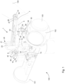
- a lift system 1 mountable on a nacelle 101 of a wind turbine 100 comprises a cantilevered beam 5 , a frame structure 10 on which the beam 5 is supported and a winch 20 mounted on the beam 5.
- the frame structure 10 comprises first, second, third and fourth upwardly extending struts 11 , 12 , 13 , 14 , respectively, connected to a proximal end 6 of the beam 5.
- the first and second struts 11 , 12, respectively, are connected at the very end of the proximal end 6 while the third and fourth struts 13 , 14 , respectively, are connected to the proximal end 6 at a position longitudinally forward, with respect to the beam 5 , of first and second struts 11 , 12.
- the frame structure 10 comprises a base 15 on which the first and second struts 11, 12 are mounted.
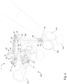
- the base 15 is mountable on first and second front gearbox pillow blocks 81 , 82 , respectively, of the nacelle 101 (see Fig.
- the base 15 may be mountable on any structure in the nacelle 101 capable of supporting the weight of the lift system.
- the third and fourth struts 13 , 14 are mountable on first and second yaw drive mounts 83 , 84 , respectively, of the nacelle 101 (see Fig. 6 ).
- the frame structure 10 further comprises a plurality of cross-braces 16 between the struts 11 , 12 , 13 , 14 to provide structural rigidity to the frame structure 10.
- a distal end 7 of the beam 5 extends longitudinally forwardly, with respect to a major axis of the nacelle 101 , which is laterally forward with respect to a vertical axis of the wind turbine 100
- the distal end 7 of the beam 5 extends over a hub 102 of a rotor 103 of the wind turbine 100 .
- the winch 20 comprises a spool with two spool halves 21, 22 mounted atop the beam 5 at the proximal end 6 of the beam 5 so that the weight of the winch 20 is borne by the frame structure 10.
- a trolley 23 is mounted on trolley skidding track 8 on an upper surface of the beam 5. The trolley 23 is movable by sliding longitudinally along the beam 5 on the trolley skidding track 8 .
- the trolley 23 may comprise a bracket that engages the upper and side surfaces of the beam 5 and the trolley skidding track 8 may comprise one or more hydraulic cylinders, with the trolley 23 mounted to one or more cylinder rods of the one or more hydraulic cylinders, whereby actuation of the one or more hydraulic cylinders to extend and retract the cylinder rods causes the trolley 23 to move longitudinally on the beam 5 .
- the trolley 23 may ride or slide on bearings between the bracket and the beam 5 , if desired.
- the spool is driven by a motor so that the two spool halves 21, 22 are driven simultaneously at the same speed.
- the cables 26, 27 are isolated on to their respective spool halves 21, 22 by a divider.
- the cables 26, 27 are reeved from the spool halves 21 , 22 through forward sheaves 31, 32, respectively, mounted on the distal end 7 of the beam 5 . From the forward sheaves 31, 32, the cables 26, 27 are reeved through trolley sheaves 33, 34, respectively, mounted and moveable with the trolley 23 .
- the cables 26, 27 are reeved through fastener block sheaves 28 , 29 , respectively, mounted on the fastener block 25 .
- the cables 26 , 27 are reeved back through the trolley sheaves 33 , 34, respectively.
- the cables 26, 27 are reeved through rearward sheaves 37 , 38 , respectively, to end terminations on the proximal end 6 of the beam 5 .
- the cables 26 , 27 are on opposite sides of the beam 5 so that the cables 26, 27 do not interfere with movement of the trolley 23 on the beam 5.
- a hook 30 or other fastener such as a lifting lug, is attached to the fastener block 25 , the hook 30 depending downwardly to be able to fasten to a convenient part of a turbine component, for example the rotor 103 (see Fig. 4 ) or a main drive shaft assembly 105 (see Fig. 8 ).
- the rearward sheaves 37 , 38 are mounted on ends of hydraulic cylinders 41, 42, respectively.
- the opposite ends of the hydraulic cylinders 41 , 42 are fixedly mounted on the beam 5 .
- Actuation of the hydraulic cylinders 41, 42 adjusts the lengths of the cables 26 , 27.
- the hydraulic cylinders 41 , 42 are independently actuatable to so that the lengths of the cables 26 , 27 can be independently and differentially adjusted. Differential adjustments of the cables 26 , 27 causes the rotor 103 to move slightly to the left or right to allow alignment of the rotor 103 with the main drive shaft assembly 105 to be able to mount the rotor 103 on the drive shaft even when there is a side-wind that causes the rotor 103 to drift.
- Differential adjustments of the cables 26 , 27 may also assist aligning the main drive shaft assembly 105 with the bearings and other components mounted in the nacelle 101 so that the main drive shaft assembly 105 may be smoothly withdrawn from the nacelle 101 .
- Sequential operation of the hydraulic cylinders 41 , 42 effectively permits steering the main drive shaft assembly 105 when necessary to smoothly remove the main drive shaft assembly 105 from the nacelle 101 by keeping a longitudinal axis of the main drive shaft assembly 105 aligned with a path required to remove the main drive shaft assembly 105 from the nacelle 101 .
- the lift system 1 may be used to lower the fully-assembled rotor 103 from atop the wind turbine 100 to the ground.
- the hook 30 is attached to the hub 102 with blades 104 of the rotor 103 still attached to the hub 102 , bolts securing the hub 102 to the nacelle 101 are loosened and the trolley 23 is moved to the distal end 7 of the beam 5 .
- the hub 102 is then dismounted from the nacelle 101 as seen in Fig. 3 , and the winch 20 operated to lower the rotor 103 as seen in Fig. 4 .
- the rotor 103 can be turned into the wind for lowering to prevent wind loading on the rotor 103 .
- the cables 26 , 27 are situated forward of the nacelle 101 so the nacelle 101 does not interfere with lowering the rotor 103 .
- a small mobile ground-based crane 90 may be attached to an end of one of the blades 104 simply to help stabilize and guide the rotor 103 while the rotor 103 is being lowered.
- Tag lines (not shown) may also be used on upwardly extending blades 104 to prevent rotation of the rotor 103 around an axis perpendicular to a plane of the blades 104 . Reversing the procedure can be done to re-install the rotor 103 .
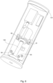
- the lift system 1 may be used to lower the fully-assembled main drive shaft assembly 105 from atop the wind turbine 100 to the ground.
- the trolley 23 is moved closer to the proximal end 6 of the beam 5 to a position over the main shaft assembly 105 where the hook 30 can be attached to the main shaft assembly 105 , for example with the assistance of a lifting tool 35.
- the lifting tool 35 may comprise an adjustment tool 36 (e.g. a manual or a hydraulic tool) to change the angle of the main drive shaft assembly 105 .
- the main drive shaft assembly 105 is slightly angled when mounted in the nacelle 101 relative to the horizontal to account for wind loading on the rotor blades 104 to prevent interference between the rotor blades 104 and a tower 106 of the wind turbine 100 when the wind is blowing.
- the angle of the main drive shaft assembly 105 is generally in a range of about 3-10° with respect to the horizontal, preferably about 3-8°, for example about 6°. In order to remove the rotor 103 from the nacelle 101 , the rotor 103 must be drawn out at this angle relative to the horizontal.
- the main drive shaft assembly 105 may need to be drawn out at a steeper angle relative to the horizontal, for example about 8.5°, to be able to clear some stud bolts. Further changing of the angle of the main drive shaft assembly 105 is accomplished with the adjustment tool 36 .
- the angles are different for different makes of wind turbine, hence a need for a way of adjusting the angle of the lifting tool 35 .
- the beam 5 is mounted on the frame structure 10 at an angle to the horizontal, the angle of the beam 5 matching the angle of the main drive shaft assembly 105 so that the trolley 23 moves along the beam 5 along a line parallel to the longitudinal axis of the main drive shaft assembly 105, thereby permitting drawing of the rotor 103 off the main drive shaft assembly 105 without the need to use the adjustment tool 36.
- the angle of the beam 5 may be adjusted by using third and fourth struts 13 , 14 of different length to match the main drive shaft assembly angle for the particular make of wind turbine.
- the adjustment tool 36 may be used to further adjust the angle of the main drive shaft assembly 105 after the rotor 103 has been drawn off the main drive shaft assembly 105 so that the main drive shaft assembly 105 can be drawn out of the nacelle 101 without the main drive shaft assembly 105 jamming on or otherwise striking the nacelle 101 .
- the main drive shaft assembly 105 is disconnected from the nacelle 101 .
- the trolley 23 is moved longitudinally forward to the distal end 7 of the beam 5 as seen in Fig. 8 so that the main drive shaft assembly 105 clears a front 109 of the nacelle 101 .
- the lifting tool 35 or the hook 30 may also have a swivel to allow rotation of the main drive shaft assembly 105 to create more clearance for the main drive shaft assembly 105 once the main drive shaft assembly 105 clears the front 109 of the nacelle 101 .
- the main shaft drive assembly 105 can then be lowered to the ground by the winch 20. Reversing the procedure can be done to re-install the main drive shaft assembly 105 .
- the lift system 1 is very large.
- a first auxiliary crane 200 may be used to lift the parts of the lift system 1 up to the nacelle 101 of the wind turbine 100 where the lift system 1 is assembled.
- the first auxiliary crane 200 is also a large crane, though not as large as the lift system 1.
- a second auxiliary crane 300 may be used to lift the parts of the first auxiliary crane 200 up to the nacelle 101 where the first auxiliary crane 200 is assembled.
- the second auxiliary crane 300 is also a large crane, though not as large as the first auxiliary crane 200 .
- a third auxiliary crane 400 may be used to lift the parts of the second auxiliary crane 300 up to the nacelle 101 where the second auxiliary crane 300 is assembled.
- the third auxiliary crane 400 may be an existing nacelle-mounted service crane that is included with the wind turbine 100 when the turbine 100 is built.
Landscapes
- Engineering & Computer Science (AREA)
- Mechanical Engineering (AREA)
- Life Sciences & Earth Sciences (AREA)
- Sustainable Development (AREA)
- Sustainable Energy (AREA)
- Chemical & Material Sciences (AREA)
- Combustion & Propulsion (AREA)
- General Engineering & Computer Science (AREA)
- Civil Engineering (AREA)
- Structural Engineering (AREA)
- Wind Motors (AREA)
Claims (16)
- Liftsystem (1), das in einer Gondel (101) einer Windturbine (100) montierbar ist, wobei das Liftsystem (1) Folgendes umfasst:einen Ausleger (5), der ein proximales Ende (6) und ein distales Ende (7) umfasst, wobei das proximale Ende des Auslegers in der Gondel (101) montierbar ist, wobei sich das distale Ende des Auslegers über eine Nabe (102) eines Rotors (103) der Windturbine (100) erstreckt, wenn das Liftsystem (1) in der Gondel montiert ist;eine Rahmenstruktur (10) zum Montieren des proximalen Endes (6) des Auslegers (5) in der Gondel;eine Winde (20), die an dem Ausleger montiert ist;eine Befestigung (25), die sich unter dem Ausleger befindet und mit der Winde (20) durch zumindest ein Kabel (26, 27) wirkverbunden ist, dadurch gekennzeichnet, dasseine Laufkatze (23) bewegbar an dem Ausleger (5) montiert ist, um Verschiebung der Laufkatze längs entlang des Auslegers zu ermöglichen, wodurch Längsbewegung der Befestigung (25) in Bezug auf den Ausleger ermöglicht wird;wobei das zumindest eine Kabel ein erstes und ein zweites Kabel (26, 27) umfasst und das erste und das zweite Kabel zwischen der Winde (20) und der Befestigung (25) jeweils an einer ersten und einer zweiten Querseite des Auslegers (5) verlaufen, sodass die Kabel (26, 27) eine Längsverschiebung der Laufkatze (23) auf dem Ausleger nicht behindern.
- Liftsystem (1) nach Anspruch 1, wobei der Ausleger (5) ein Balken ist.
- Liftsystem (1) nach Anspruch 1 oder Anspruch 2, wobei Längen des ersten und des zweiten Kabels (26, 27) unabhängig einstellbar sind, um Lenkung einer Last, die mit der Befestigung (25) verbunden ist, zu ermöglichen.
- Liftsystem (1) nach Anspruch 3, wobei das erste Kabel (26) mit einem ersten Hydraulikzylinder (41) verknüpft ist, der auf der ersten Seite des Balkens (5) montiert ist, und das zweite Kabel (27) mit einem zweiten Hydraulikzylinder (42) verknüpft ist, der auf der zweiten Seite des Balkens (5) montiert ist, wobei der erste und der zweite Hydraulikzylinder unabhängig betätigbar sind, um die Längen des ersten und des zweiten Kabels (26, 27) unabhängig einzustellen.
- Liftsystem (1) nach einem der Ansprüche 1 bis 4, wobei die Windturbine (100) ferner eine Hauptantriebswelle (105) umfasst, die in der Gondel (101) montiert ist, wobei die Hauptantriebswelle (105) eine Längsachse aufweist, die in einem Winkel ungleich Null weg von horizontal ausgerichtet ist, und wobei der Ausleger (5) eine Längsachse aufweist, die im Wesentlichen parallel zu der Längsachse der Hauptantriebswelle ist.
- Liftsystem (1) nach Anspruch 5, wobei der Winkel ungleich Null in einem Bereich von 3-10° ist.
- Liftsystem (1) nach Anspruch 5 oder Anspruch 6, wobei sich die Laufkatze (23) längs entlang eines Weges im Wesentlichen parallel zu der Längsachse der Hauptantriebswelle (105) verschiebt.
- Liftsystem (1) nach einem der Ansprüche 1 bis 7, wobei die Winde (20) an einer oberen Oberfläche des Auslegers (5) montiert ist.
- Liftsystem (1) nach einem der Ansprüche 1 bis 7, wobei die Winde (20) unter dem Ausleger (5) montiert ist.
- Liftsystem (1) nach einem der Ansprüche 1 bis 7, wobei die Winde (20) an der Laufkatze (23) montiert ist und sich mit der Laufkatze bewegt.
- Liftsystem (1) nach einem der Ansprüche 1 bis 10, wobei die Rahmenstruktur (10) Folgendes umfasst: eine Montagebasis (15), die an einer Struktur in der Gondel (101) montierbar und in der Lage ist, alle Kräfte zu stützen, die der Gondel durch das Liftsystem (1) verliehen werden; und eine Vielzahl von sich nach oben erstreckenden Stützstreben (11, 12, 13, 14), wobei zumindest eine der Stützstreben auf der Montagebasis (15) stützbar ist und zumindest eine der Stützstreben an einer Position in der Gondel in der Nähe eines Hauptlagers der Windturbine (100) montierbar ist.
- Liftsystem (1) nach Anspruch 11, wobei die Vielzahl von sich nach oben erstreckenden Stützstreben (11, 12, 13, 14) eine erste Strebe (11), die an der Montagebasis (15) über einem ersten Getriebekissenblock (81) der Gondel (101) montierbar ist, eine zweite Strebe (12), die an der Montagebasis (15) über einem zweiten Getriebekissenblock (82) der Gondel montierbar ist, eine dritte Strebe (13), die an einer ersten Position in der Gondel in der Nähe des Hauptlagers montierbar ist, und eine vierte Strebe (14), die an einer zweiten Position in der Gondel in der Nähe des Hauptlagers montierbar ist, umfasst.
- Liftsystem (1) nach Anspruch 12, wobei sich die Laufkatze (23) quer über Querseiten des Auslegers (5) hinaus erstreckt, die zumindest eine Laufkatzenscheibe (33, 34) eine erste Laufkatzenscheibe (33) auf einer ersten Querseite des Auslegers und eine zweite Laufkatzenscheibe (34) auf einer zweiten Querseite des Auslegers umfasst und das zumindest eine Kabel (26, 27) durch die erste und die zweite Laufkatzenscheibe (33, 34) geführt ist.
- Liftsystem (1) nach einem der Ansprüche 11 bis 13, wobei die Struktur, die in der Lage ist, das Gewicht des Liftsystems (1) zu stützen, Kissenblöcke eines Getriebes (81, 82) der Windturbine (100) umfasst.
- Liftsystem (1) nach einem der Ansprüche 1 bis 14, wobei die Befestigung (25) einen Haken (30) oder eine Liftöse umfasst.
- Liftsystem (1) nach einem der Ansprüche 1 bis 15, wobei der Baum (5) eine Gleitschiene (8) der Laufkatze (23) umfasst, an der die Laufkatze bewegbar montiert ist.
Applications Claiming Priority (3)
| Application Number | Priority Date | Filing Date | Title |
|---|---|---|---|
| US201862667458P | 2018-05-05 | 2018-05-05 | |
| US201862775687P | 2018-12-05 | 2018-12-05 | |
| PCT/CA2019/050568 WO2019213748A1 (en) | 2018-05-05 | 2019-05-01 | Nacelle mountable lift system for a wind turbine |
Publications (4)
| Publication Number | Publication Date |
|---|---|
| EP3765737A1 EP3765737A1 (de) | 2021-01-20 |
| EP3765737A4 EP3765737A4 (de) | 2022-01-12 |
| EP3765737B1 true EP3765737B1 (de) | 2024-12-18 |
| EP3765737C0 EP3765737C0 (de) | 2024-12-18 |
Family
ID=68467186
Family Applications (1)
| Application Number | Title | Priority Date | Filing Date |
|---|---|---|---|
| EP19800561.3A Active EP3765737B1 (de) | 2018-05-05 | 2019-05-01 | Gondel-montierbares liftsystem für eine windturbine |
Country Status (6)
| Country | Link |
|---|---|
| US (2) | US11459216B2 (de) |
| EP (1) | EP3765737B1 (de) |
| CA (1) | CA3096280C (de) |
| ES (1) | ES3004384T3 (de) |
| PL (1) | PL3765737T3 (de) |
| WO (1) | WO2019213748A1 (de) |
Families Citing this family (4)
| Publication number | Priority date | Publication date | Assignee | Title |
|---|---|---|---|---|
| CN110925149B (zh) * | 2019-12-13 | 2020-11-24 | 河北新天科创新能源技术有限公司 | 一种风力发电机的齿轮箱塔上维修方法 |
| WO2021168549A1 (en) | 2020-02-28 | 2021-09-02 | LiftWerx Holdings Inc. | Multiple up-tower lifting appliances on wind turbines |
| EP4602264A1 (de) * | 2022-10-11 | 2025-08-20 | Vestas Wind Systems A/S | Verfahren zur handhabung einer windturbinenschaufel mit einem kransystem |
| EP4474640A1 (de) * | 2023-06-07 | 2024-12-11 | General Electric Renovables España, S.L. | Verfahren zur wartung oder installation einer komponente einer windturbine mithilfe eines krans |
Family Cites Families (11)
| Publication number | Priority date | Publication date | Assignee | Title |
|---|---|---|---|---|
| US2994513A (en) * | 1959-09-29 | 1961-08-01 | Alliance Machine Co | Dual hook block hoists |
| EP1291521A1 (de) | 2001-09-06 | 2003-03-12 | Turbowinds N.V./S.A. | Windkraftanlage mit bewegbarem Bordkran |
| ES2423430T3 (es) * | 2003-09-26 | 2013-09-20 | Vestas Wind Systems A/S | Equipo para ser montado en el buje de una turbina eólica y procedimiento para realizar el mantenimiento de una turbina eólica utilizando tal equipo |
| ES2316200B1 (es) * | 2004-12-21 | 2010-01-11 | GAMESA INNOVATION & TECHNOLOGY, S.L. | Aerogenerador con grua desmontable y pescante auxiliar y procedimiento de montaje de dicha grua. |
| DE102006013539A1 (de) | 2006-03-24 | 2007-09-27 | Nordex Energy Gmbh | Windenergieanlage mit einer Halteeinrichtung für eine Rotorwelle |
| KR101038641B1 (ko) * | 2008-09-01 | 2011-06-03 | 두산중공업 주식회사 | 풍력터빈설비의 유지 보수 시스템 |
| CN101603511B (zh) * | 2009-07-16 | 2011-07-27 | 广州雅图风电设备制造有限公司 | 一种垂直风力发电机 |
| WO2012105971A1 (en) * | 2011-02-02 | 2012-08-09 | Smith Matthew K | Nacelle-mounted maintenance system for wind turbines |
| CN102491162B (zh) | 2011-11-24 | 2014-05-07 | 北京金风科创风电设备有限公司 | 吊装设备和吊装方法 |
| DK177629B1 (da) | 2012-11-06 | 2014-01-06 | Liftra Ip Aps | Dobbelt wirestyr til en krankrøje |
| EP3504149B1 (de) | 2016-08-29 | 2020-10-07 | MHI Vestas Offshore Wind A/S | Verfahren und vorrichtung zur durchführung von wartungsarbeiten an einer windturbinenkomponente |
-
2019
- 2019-05-01 PL PL19800561.3T patent/PL3765737T3/pl unknown
- 2019-05-01 EP EP19800561.3A patent/EP3765737B1/de active Active
- 2019-05-01 US US17/045,196 patent/US11459216B2/en active Active
- 2019-05-01 WO PCT/CA2019/050568 patent/WO2019213748A1/en not_active Ceased
- 2019-05-01 CA CA3096280A patent/CA3096280C/en active Active
- 2019-05-01 ES ES19800561T patent/ES3004384T3/es active Active
-
2022
- 2022-06-03 US US17/831,596 patent/US11866306B2/en active Active
Also Published As
| Publication number | Publication date |
|---|---|
| US20220289529A1 (en) | 2022-09-15 |
| CA3096280C (en) | 2021-01-26 |
| ES3004384T3 (en) | 2025-03-12 |
| PL3765737T3 (pl) | 2025-03-17 |
| EP3765737C0 (de) | 2024-12-18 |
| EP3765737A1 (de) | 2021-01-20 |
| US11866306B2 (en) | 2024-01-09 |
| US11459216B2 (en) | 2022-10-04 |
| US20210047155A1 (en) | 2021-02-18 |
| WO2019213748A1 (en) | 2019-11-14 |
| EP3765737A4 (de) | 2022-01-12 |
| CA3096280A1 (en) | 2019-11-14 |
Similar Documents
| Publication | Publication Date | Title |
|---|---|---|
| US11866306B2 (en) | Nacelle mountable lift system for a wind turbine | |
| US20230003195A1 (en) | Method for assembling a wind turbine and a wind turbine system | |
| DE102009056245B4 (de) | Windenergieanlage mit Hebevorrichtung | |
| EP2494199A1 (de) | Vorrichtung zur herstellung einer erlaubnis und zum transport von gepäck zu und von einer windturbinenkonstruktion über dem meeresspiegel | |
| US20150014266A1 (en) | Revolving tower crane | |
| KR20150135246A (ko) | 풍력 터빈의 회전자 블레이드를 배치하기 위한 장치 및 방법 | |
| EP3132137B1 (de) | Mobile kranvorrichtung sowie verfahren zur temporären montage einer solchen kranvorrichtung | |
| WO2020038532A1 (de) | Vorrichtung zum anordnen eines aufzugsystems und verfahren zum ausrichten der vorrichtung | |
| EP3519343A1 (de) | Hebeanordnung | |
| EP3676493B1 (de) | Windturbine mit einem transportsystem zum bewegen von antriebsstrangkomponenten | |
| GB2577643A (en) | Method for assembling a wind turbine and a wind turbine system | |
| WO2019042508A1 (en) | TRANSPORT SYSTEM FOR MOVING TRANSMISSION COMPONENTS | |
| WO2019042507A1 (en) | METHOD FOR MOUNTING OR DISASSEMBLING A WIND ELEMENT | |
| DE102016004348A1 (de) | Mobile Kranvorrichtung sowie Verfahren zur temporären Montage einer solchen Kranvorrichtung | |
| CN109357860A (zh) | 弯道模拟机构、车钩连挂试验台及其试验系统 | |
| NL2038697B1 (en) | Steering line system for a crane and method for controlling a load lifted with a crane | |
| DE202005019439U1 (de) | Hebebühne | |
| CN217051347U (zh) | 一种发电机更换装置 | |
| CN223032077U (zh) | 一种风机组件的提升转运装置 | |
| CN220746909U (zh) | 一种桩机底盘及桩机 | |
| CA3060486C (en) | Method for assembling a wind turbine and a wind turbine system | |
| EP3536951A1 (de) | Hebeausrüstung zur verwendung in beengten räumen | |
| CN119117910A (zh) | 一种高桩码头梁板架设一体设备 | |
| DE102025138556A1 (de) | Winden-Vorrichtung | |
| CN120097216A (zh) | 一种升沉补偿工装、升沉补偿系统及升沉补偿方法 |
Legal Events
| Date | Code | Title | Description |
|---|---|---|---|
| STAA | Information on the status of an ep patent application or granted ep patent |
Free format text: STATUS: THE INTERNATIONAL PUBLICATION HAS BEEN MADE |
|
| PUAI | Public reference made under article 153(3) epc to a published international application that has entered the european phase |
Free format text: ORIGINAL CODE: 0009012 |
|
| STAA | Information on the status of an ep patent application or granted ep patent |
Free format text: STATUS: REQUEST FOR EXAMINATION WAS MADE |
|
| 17P | Request for examination filed |
Effective date: 20201014 |
|
| AK | Designated contracting states |
Kind code of ref document: A1 Designated state(s): AL AT BE BG CH CY CZ DE DK EE ES FI FR GB GR HR HU IE IS IT LI LT LU LV MC MK MT NL NO PL PT RO RS SE SI SK SM TR |
|
| AX | Request for extension of the european patent |
Extension state: BA ME |
|
| DAV | Request for validation of the european patent (deleted) | ||
| DAX | Request for extension of the european patent (deleted) | ||
| A4 | Supplementary search report drawn up and despatched |
Effective date: 20211215 |
|
| RIC1 | Information provided on ipc code assigned before grant |
Ipc: F03D 80/80 20160101ALI20211209BHEP Ipc: B66C 23/18 20060101ALI20211209BHEP Ipc: F03D 13/10 20160101AFI20211209BHEP |
|
| STAA | Information on the status of an ep patent application or granted ep patent |
Free format text: STATUS: EXAMINATION IS IN PROGRESS |
|
| 17Q | First examination report despatched |
Effective date: 20230731 |
|
| GRAP | Despatch of communication of intention to grant a patent |
Free format text: ORIGINAL CODE: EPIDOSNIGR1 |
|
| STAA | Information on the status of an ep patent application or granted ep patent |
Free format text: STATUS: GRANT OF PATENT IS INTENDED |
|
| RIC1 | Information provided on ipc code assigned before grant |
Ipc: F03D 80/50 20160101ALI20240703BHEP Ipc: B66C 23/20 20060101ALI20240703BHEP Ipc: B66C 1/10 20060101ALI20240703BHEP Ipc: F03D 80/80 20160101ALI20240703BHEP Ipc: B66C 23/18 20060101ALI20240703BHEP Ipc: F03D 13/10 20160101AFI20240703BHEP |
|
| INTG | Intention to grant announced |
Effective date: 20240725 |
|
| GRAJ | Information related to disapproval of communication of intention to grant by the applicant or resumption of examination proceedings by the epo deleted |
Free format text: ORIGINAL CODE: EPIDOSDIGR1 |
|
| STAA | Information on the status of an ep patent application or granted ep patent |
Free format text: STATUS: EXAMINATION IS IN PROGRESS |
|
| RIN1 | Information on inventor provided before grant (corrected) |
Inventor name: BAKKER, RUUD Inventor name: AITKEN, GLEN D. |
|
| INTC | Intention to grant announced (deleted) | ||
| GRAP | Despatch of communication of intention to grant a patent |
Free format text: ORIGINAL CODE: EPIDOSNIGR1 |
|
| STAA | Information on the status of an ep patent application or granted ep patent |
Free format text: STATUS: GRANT OF PATENT IS INTENDED |
|
| GRAS | Grant fee paid |
Free format text: ORIGINAL CODE: EPIDOSNIGR3 |
|
| RAP3 | Party data changed (applicant data changed or rights of an application transferred) |
Owner name: LIFTWERX SOLUTIONS INC. |
|
| GRAA | (expected) grant |
Free format text: ORIGINAL CODE: 0009210 |
|
| STAA | Information on the status of an ep patent application or granted ep patent |
Free format text: STATUS: THE PATENT HAS BEEN GRANTED |
|
| INTG | Intention to grant announced |
Effective date: 20241106 |
|
| AK | Designated contracting states |
Kind code of ref document: B1 Designated state(s): AL AT BE BG CH CY CZ DE DK EE ES FI FR GB GR HR HU IE IS IT LI LT LU LV MC MK MT NL NO PL PT RO RS SE SI SK SM TR |
|
| REG | Reference to a national code |
Ref country code: CH Ref legal event code: EP |
|
| REG | Reference to a national code |
Ref country code: DE Ref legal event code: R096 Ref document number: 602019063728 Country of ref document: DE |
|
| REG | Reference to a national code |
Ref country code: IE Ref legal event code: FG4D |
|
| U01 | Request for unitary effect filed |
Effective date: 20250109 |
|
| U07 | Unitary effect registered |
Designated state(s): AT BE BG DE DK EE FI FR IT LT LU LV MT NL PT RO SE SI Effective date: 20250116 |
|
| REG | Reference to a national code |
Ref country code: ES Ref legal event code: FG2A Ref document number: 3004384 Country of ref document: ES Kind code of ref document: T3 Effective date: 20250312 |
|
| PG25 | Lapsed in a contracting state [announced via postgrant information from national office to epo] |
Ref country code: HR Free format text: LAPSE BECAUSE OF FAILURE TO SUBMIT A TRANSLATION OF THE DESCRIPTION OR TO PAY THE FEE WITHIN THE PRESCRIBED TIME-LIMIT Effective date: 20241218 |
|
| PG25 | Lapsed in a contracting state [announced via postgrant information from national office to epo] |
Ref country code: GR Free format text: LAPSE BECAUSE OF FAILURE TO SUBMIT A TRANSLATION OF THE DESCRIPTION OR TO PAY THE FEE WITHIN THE PRESCRIBED TIME-LIMIT Effective date: 20250319 |
|
| PG25 | Lapsed in a contracting state [announced via postgrant information from national office to epo] |
Ref country code: RS Free format text: LAPSE BECAUSE OF FAILURE TO SUBMIT A TRANSLATION OF THE DESCRIPTION OR TO PAY THE FEE WITHIN THE PRESCRIBED TIME-LIMIT Effective date: 20250318 |
|
| U20 | Renewal fee for the european patent with unitary effect paid |
Year of fee payment: 7 Effective date: 20250414 |
|
| PG25 | Lapsed in a contracting state [announced via postgrant information from national office to epo] |
Ref country code: SM Free format text: LAPSE BECAUSE OF FAILURE TO SUBMIT A TRANSLATION OF THE DESCRIPTION OR TO PAY THE FEE WITHIN THE PRESCRIBED TIME-LIMIT Effective date: 20241218 |
|
| PGFP | Annual fee paid to national office [announced via postgrant information from national office to epo] |
Ref country code: PL Payment date: 20250428 Year of fee payment: 7 |
|
| PGFP | Annual fee paid to national office [announced via postgrant information from national office to epo] |
Ref country code: GB Payment date: 20250414 Year of fee payment: 7 Ref country code: ES Payment date: 20250606 Year of fee payment: 7 |
|
| PG25 | Lapsed in a contracting state [announced via postgrant information from national office to epo] |
Ref country code: IS Free format text: LAPSE BECAUSE OF FAILURE TO SUBMIT A TRANSLATION OF THE DESCRIPTION OR TO PAY THE FEE WITHIN THE PRESCRIBED TIME-LIMIT Effective date: 20250418 |
|
| PGFP | Annual fee paid to national office [announced via postgrant information from national office to epo] |
Ref country code: NO Payment date: 20250521 Year of fee payment: 7 |
|
| PG25 | Lapsed in a contracting state [announced via postgrant information from national office to epo] |
Ref country code: SK Free format text: LAPSE BECAUSE OF FAILURE TO SUBMIT A TRANSLATION OF THE DESCRIPTION OR TO PAY THE FEE WITHIN THE PRESCRIBED TIME-LIMIT Effective date: 20241218 |
|
| PGFP | Annual fee paid to national office [announced via postgrant information from national office to epo] |
Ref country code: TR Payment date: 20250417 Year of fee payment: 7 |
|
| PG25 | Lapsed in a contracting state [announced via postgrant information from national office to epo] |
Ref country code: CZ Free format text: LAPSE BECAUSE OF FAILURE TO SUBMIT A TRANSLATION OF THE DESCRIPTION OR TO PAY THE FEE WITHIN THE PRESCRIBED TIME-LIMIT Effective date: 20241218 |
|
| PGFP | Annual fee paid to national office [announced via postgrant information from national office to epo] |
Ref country code: IE Payment date: 20250522 Year of fee payment: 7 |
|
| PLBE | No opposition filed within time limit |
Free format text: ORIGINAL CODE: 0009261 |
|
| STAA | Information on the status of an ep patent application or granted ep patent |
Free format text: STATUS: NO OPPOSITION FILED WITHIN TIME LIMIT |
|
| REG | Reference to a national code |
Ref country code: CH Ref legal event code: L10 Free format text: ST27 STATUS EVENT CODE: U-0-0-L10-L00 (AS PROVIDED BY THE NATIONAL OFFICE) Effective date: 20251029 |
|
| 26N | No opposition filed |
Effective date: 20250919 |
|
| REG | Reference to a national code |
Ref country code: CH Ref legal event code: H13 Free format text: ST27 STATUS EVENT CODE: U-0-0-H10-H13 (AS PROVIDED BY THE NATIONAL OFFICE) Effective date: 20251223 |
|
| PG25 | Lapsed in a contracting state [announced via postgrant information from national office to epo] |
Ref country code: CH Free format text: LAPSE BECAUSE OF NON-PAYMENT OF DUE FEES Effective date: 20250531 |
|
| PG25 | Lapsed in a contracting state [announced via postgrant information from national office to epo] |
Ref country code: MC Free format text: LAPSE BECAUSE OF FAILURE TO SUBMIT A TRANSLATION OF THE DESCRIPTION OR TO PAY THE FEE WITHIN THE PRESCRIBED TIME-LIMIT Effective date: 20241218 |