EP3765745B1 - Steuerung einer flüssigkeitsringpumpe - Google Patents
Steuerung einer flüssigkeitsringpumpe Download PDFInfo
- Publication number
- EP3765745B1 EP3765745B1 EP19768178.6A EP19768178A EP3765745B1 EP 3765745 B1 EP3765745 B1 EP 3765745B1 EP 19768178 A EP19768178 A EP 19768178A EP 3765745 B1 EP3765745 B1 EP 3765745B1
- Authority
- EP
- European Patent Office
- Prior art keywords
- liquid
- ring pump
- controller
- operating
- liquid ring
- Prior art date
- Legal status (The legal status is an assumption and is not a legal conclusion. Google has not performed a legal analysis and makes no representation as to the accuracy of the status listed.)
- Active
Links
Images


Classifications
-
- F—MECHANICAL ENGINEERING; LIGHTING; HEATING; WEAPONS; BLASTING
- F04—POSITIVE - DISPLACEMENT MACHINES FOR LIQUIDS; PUMPS FOR LIQUIDS OR ELASTIC FLUIDS
- F04C—ROTARY-PISTON, OR OSCILLATING-PISTON, POSITIVE-DISPLACEMENT MACHINES FOR LIQUIDS; ROTARY-PISTON, OR OSCILLATING-PISTON, POSITIVE-DISPLACEMENT PUMPS
- F04C19/00—Rotary-piston pumps with fluid ring or the like, specially adapted for elastic fluids
-
- F—MECHANICAL ENGINEERING; LIGHTING; HEATING; WEAPONS; BLASTING
- F04—POSITIVE - DISPLACEMENT MACHINES FOR LIQUIDS; PUMPS FOR LIQUIDS OR ELASTIC FLUIDS
- F04C—ROTARY-PISTON, OR OSCILLATING-PISTON, POSITIVE-DISPLACEMENT MACHINES FOR LIQUIDS; ROTARY-PISTON, OR OSCILLATING-PISTON, POSITIVE-DISPLACEMENT PUMPS
- F04C19/00—Rotary-piston pumps with fluid ring or the like, specially adapted for elastic fluids
- F04C19/001—General arrangements, plants, flowsheets
-
- F—MECHANICAL ENGINEERING; LIGHTING; HEATING; WEAPONS; BLASTING
- F04—POSITIVE - DISPLACEMENT MACHINES FOR LIQUIDS; PUMPS FOR LIQUIDS OR ELASTIC FLUIDS
- F04C—ROTARY-PISTON, OR OSCILLATING-PISTON, POSITIVE-DISPLACEMENT MACHINES FOR LIQUIDS; ROTARY-PISTON, OR OSCILLATING-PISTON, POSITIVE-DISPLACEMENT PUMPS
- F04C19/00—Rotary-piston pumps with fluid ring or the like, specially adapted for elastic fluids
- F04C19/004—Details concerning the operating liquid, e.g. nature, separation, cooling, cleaning, control of the supply
-
- F—MECHANICAL ENGINEERING; LIGHTING; HEATING; WEAPONS; BLASTING
- F04—POSITIVE - DISPLACEMENT MACHINES FOR LIQUIDS; PUMPS FOR LIQUIDS OR ELASTIC FLUIDS
- F04C—ROTARY-PISTON, OR OSCILLATING-PISTON, POSITIVE-DISPLACEMENT MACHINES FOR LIQUIDS; ROTARY-PISTON, OR OSCILLATING-PISTON, POSITIVE-DISPLACEMENT PUMPS
- F04C19/00—Rotary-piston pumps with fluid ring or the like, specially adapted for elastic fluids
- F04C19/005—Details concerning the admission or discharge
- F04C19/007—Port members in the form of side plates
-
- F—MECHANICAL ENGINEERING; LIGHTING; HEATING; WEAPONS; BLASTING
- F04—POSITIVE - DISPLACEMENT MACHINES FOR LIQUIDS; PUMPS FOR LIQUIDS OR ELASTIC FLUIDS
- F04C—ROTARY-PISTON, OR OSCILLATING-PISTON, POSITIVE-DISPLACEMENT MACHINES FOR LIQUIDS; ROTARY-PISTON, OR OSCILLATING-PISTON, POSITIVE-DISPLACEMENT PUMPS
- F04C25/00—Adaptations of pumps for special use of pumps for elastic fluids
- F04C25/02—Adaptations of pumps for special use of pumps for elastic fluids for producing high vacuum
-
- F—MECHANICAL ENGINEERING; LIGHTING; HEATING; WEAPONS; BLASTING
- F04—POSITIVE - DISPLACEMENT MACHINES FOR LIQUIDS; PUMPS FOR LIQUIDS OR ELASTIC FLUIDS
- F04C—ROTARY-PISTON, OR OSCILLATING-PISTON, POSITIVE-DISPLACEMENT MACHINES FOR LIQUIDS; ROTARY-PISTON, OR OSCILLATING-PISTON, POSITIVE-DISPLACEMENT PUMPS
- F04C27/00—Sealing arrangements in rotary-piston pumps specially adapted for elastic fluids
- F04C27/02—Liquid sealing for high-vacuum pumps or for compressors
-
- F—MECHANICAL ENGINEERING; LIGHTING; HEATING; WEAPONS; BLASTING
- F04—POSITIVE - DISPLACEMENT MACHINES FOR LIQUIDS; PUMPS FOR LIQUIDS OR ELASTIC FLUIDS
- F04C—ROTARY-PISTON, OR OSCILLATING-PISTON, POSITIVE-DISPLACEMENT MACHINES FOR LIQUIDS; ROTARY-PISTON, OR OSCILLATING-PISTON, POSITIVE-DISPLACEMENT PUMPS
- F04C28/00—Control of, monitoring of, or safety arrangements for, pumps or pumping installations specially adapted for elastic fluids
-
- F—MECHANICAL ENGINEERING; LIGHTING; HEATING; WEAPONS; BLASTING
- F04—POSITIVE - DISPLACEMENT MACHINES FOR LIQUIDS; PUMPS FOR LIQUIDS OR ELASTIC FLUIDS
- F04C—ROTARY-PISTON, OR OSCILLATING-PISTON, POSITIVE-DISPLACEMENT MACHINES FOR LIQUIDS; ROTARY-PISTON, OR OSCILLATING-PISTON, POSITIVE-DISPLACEMENT PUMPS
- F04C28/00—Control of, monitoring of, or safety arrangements for, pumps or pumping installations specially adapted for elastic fluids
- F04C28/08—Control of, monitoring of, or safety arrangements for, pumps or pumping installations specially adapted for elastic fluids characterised by varying the rotational speed
-
- F—MECHANICAL ENGINEERING; LIGHTING; HEATING; WEAPONS; BLASTING
- F04—POSITIVE - DISPLACEMENT MACHINES FOR LIQUIDS; PUMPS FOR LIQUIDS OR ELASTIC FLUIDS
- F04C—ROTARY-PISTON, OR OSCILLATING-PISTON, POSITIVE-DISPLACEMENT MACHINES FOR LIQUIDS; ROTARY-PISTON, OR OSCILLATING-PISTON, POSITIVE-DISPLACEMENT PUMPS
- F04C28/00—Control of, monitoring of, or safety arrangements for, pumps or pumping installations specially adapted for elastic fluids
- F04C28/24—Control of, monitoring of, or safety arrangements for, pumps or pumping installations specially adapted for elastic fluids characterised by using valves controlling pressure or flow rate, e.g. discharge valves or unloading valves
-
- F—MECHANICAL ENGINEERING; LIGHTING; HEATING; WEAPONS; BLASTING
- F04—POSITIVE - DISPLACEMENT MACHINES FOR LIQUIDS; PUMPS FOR LIQUIDS OR ELASTIC FLUIDS
- F04C—ROTARY-PISTON, OR OSCILLATING-PISTON, POSITIVE-DISPLACEMENT MACHINES FOR LIQUIDS; ROTARY-PISTON, OR OSCILLATING-PISTON, POSITIVE-DISPLACEMENT PUMPS
- F04C28/00—Control of, monitoring of, or safety arrangements for, pumps or pumping installations specially adapted for elastic fluids
- F04C28/28—Safety arrangements; Monitoring
-
- F—MECHANICAL ENGINEERING; LIGHTING; HEATING; WEAPONS; BLASTING
- F04—POSITIVE - DISPLACEMENT MACHINES FOR LIQUIDS; PUMPS FOR LIQUIDS OR ELASTIC FLUIDS
- F04C—ROTARY-PISTON, OR OSCILLATING-PISTON, POSITIVE-DISPLACEMENT MACHINES FOR LIQUIDS; ROTARY-PISTON, OR OSCILLATING-PISTON, POSITIVE-DISPLACEMENT PUMPS
- F04C7/00—Rotary-piston machines or pumps with fluid ring or the like
-
- F—MECHANICAL ENGINEERING; LIGHTING; HEATING; WEAPONS; BLASTING
- F04—POSITIVE - DISPLACEMENT MACHINES FOR LIQUIDS; PUMPS FOR LIQUIDS OR ELASTIC FLUIDS
- F04D—NON-POSITIVE-DISPLACEMENT PUMPS
- F04D17/00—Radial-flow pumps, e.g. centrifugal pumps; Helico-centrifugal pumps
- F04D17/08—Centrifugal pumps
- F04D17/10—Centrifugal pumps for compressing or evacuating
-
- F—MECHANICAL ENGINEERING; LIGHTING; HEATING; WEAPONS; BLASTING
- F04—POSITIVE - DISPLACEMENT MACHINES FOR LIQUIDS; PUMPS FOR LIQUIDS OR ELASTIC FLUIDS
- F04D—NON-POSITIVE-DISPLACEMENT PUMPS
- F04D27/00—Control, e.g. regulation, of pumps, pumping installations or pumping systems specially adapted for elastic fluids
-
- F—MECHANICAL ENGINEERING; LIGHTING; HEATING; WEAPONS; BLASTING
- F04—POSITIVE - DISPLACEMENT MACHINES FOR LIQUIDS; PUMPS FOR LIQUIDS OR ELASTIC FLUIDS
- F04D—NON-POSITIVE-DISPLACEMENT PUMPS
- F04D29/00—Details, component parts, or accessories
- F04D29/08—Sealings
- F04D29/083—Sealings especially adapted for elastic fluid pumps
-
- F—MECHANICAL ENGINEERING; LIGHTING; HEATING; WEAPONS; BLASTING
- F04—POSITIVE - DISPLACEMENT MACHINES FOR LIQUIDS; PUMPS FOR LIQUIDS OR ELASTIC FLUIDS
- F04C—ROTARY-PISTON, OR OSCILLATING-PISTON, POSITIVE-DISPLACEMENT MACHINES FOR LIQUIDS; ROTARY-PISTON, OR OSCILLATING-PISTON, POSITIVE-DISPLACEMENT PUMPS
- F04C2240/00—Components
- F04C2240/80—Other components
- F04C2240/81—Sensor, e.g. electronic sensor for control or monitoring
-
- F—MECHANICAL ENGINEERING; LIGHTING; HEATING; WEAPONS; BLASTING
- F04—POSITIVE - DISPLACEMENT MACHINES FOR LIQUIDS; PUMPS FOR LIQUIDS OR ELASTIC FLUIDS
- F04C—ROTARY-PISTON, OR OSCILLATING-PISTON, POSITIVE-DISPLACEMENT MACHINES FOR LIQUIDS; ROTARY-PISTON, OR OSCILLATING-PISTON, POSITIVE-DISPLACEMENT PUMPS
- F04C2270/00—Control; Monitoring or safety arrangements
- F04C2270/05—Speed
- F04C2270/052—Speed angular
- F04C2270/0525—Controlled or regulated
-
- F—MECHANICAL ENGINEERING; LIGHTING; HEATING; WEAPONS; BLASTING
- F04—POSITIVE - DISPLACEMENT MACHINES FOR LIQUIDS; PUMPS FOR LIQUIDS OR ELASTIC FLUIDS
- F04C—ROTARY-PISTON, OR OSCILLATING-PISTON, POSITIVE-DISPLACEMENT MACHINES FOR LIQUIDS; ROTARY-PISTON, OR OSCILLATING-PISTON, POSITIVE-DISPLACEMENT PUMPS
- F04C2270/00—Control; Monitoring or safety arrangements
- F04C2270/18—Pressure
-
- F—MECHANICAL ENGINEERING; LIGHTING; HEATING; WEAPONS; BLASTING
- F04—POSITIVE - DISPLACEMENT MACHINES FOR LIQUIDS; PUMPS FOR LIQUIDS OR ELASTIC FLUIDS
- F04C—ROTARY-PISTON, OR OSCILLATING-PISTON, POSITIVE-DISPLACEMENT MACHINES FOR LIQUIDS; ROTARY-PISTON, OR OSCILLATING-PISTON, POSITIVE-DISPLACEMENT PUMPS
- F04C2270/00—Control; Monitoring or safety arrangements
- F04C2270/18—Pressure
- F04C2270/185—Controlled or regulated
-
- F—MECHANICAL ENGINEERING; LIGHTING; HEATING; WEAPONS; BLASTING
- F04—POSITIVE - DISPLACEMENT MACHINES FOR LIQUIDS; PUMPS FOR LIQUIDS OR ELASTIC FLUIDS
- F04C—ROTARY-PISTON, OR OSCILLATING-PISTON, POSITIVE-DISPLACEMENT MACHINES FOR LIQUIDS; ROTARY-PISTON, OR OSCILLATING-PISTON, POSITIVE-DISPLACEMENT PUMPS
- F04C2270/00—Control; Monitoring or safety arrangements
- F04C2270/19—Temperature
-
- F—MECHANICAL ENGINEERING; LIGHTING; HEATING; WEAPONS; BLASTING
- F04—POSITIVE - DISPLACEMENT MACHINES FOR LIQUIDS; PUMPS FOR LIQUIDS OR ELASTIC FLUIDS
- F04C—ROTARY-PISTON, OR OSCILLATING-PISTON, POSITIVE-DISPLACEMENT MACHINES FOR LIQUIDS; ROTARY-PISTON, OR OSCILLATING-PISTON, POSITIVE-DISPLACEMENT PUMPS
- F04C2270/00—Control; Monitoring or safety arrangements
- F04C2270/19—Temperature
- F04C2270/195—Controlled or regulated
-
- F—MECHANICAL ENGINEERING; LIGHTING; HEATING; WEAPONS; BLASTING
- F04—POSITIVE - DISPLACEMENT MACHINES FOR LIQUIDS; PUMPS FOR LIQUIDS OR ELASTIC FLUIDS
- F04C—ROTARY-PISTON, OR OSCILLATING-PISTON, POSITIVE-DISPLACEMENT MACHINES FOR LIQUIDS; ROTARY-PISTON, OR OSCILLATING-PISTON, POSITIVE-DISPLACEMENT PUMPS
- F04C2270/00—Control; Monitoring or safety arrangements
- F04C2270/20—Flow
- F04C2270/205—Controlled or regulated
-
- F—MECHANICAL ENGINEERING; LIGHTING; HEATING; WEAPONS; BLASTING
- F04—POSITIVE - DISPLACEMENT MACHINES FOR LIQUIDS; PUMPS FOR LIQUIDS OR ELASTIC FLUIDS
- F04C—ROTARY-PISTON, OR OSCILLATING-PISTON, POSITIVE-DISPLACEMENT MACHINES FOR LIQUIDS; ROTARY-PISTON, OR OSCILLATING-PISTON, POSITIVE-DISPLACEMENT PUMPS
- F04C2270/00—Control; Monitoring or safety arrangements
- F04C2270/21—Pressure difference
-
- F—MECHANICAL ENGINEERING; LIGHTING; HEATING; WEAPONS; BLASTING
- F04—POSITIVE - DISPLACEMENT MACHINES FOR LIQUIDS; PUMPS FOR LIQUIDS OR ELASTIC FLUIDS
- F04C—ROTARY-PISTON, OR OSCILLATING-PISTON, POSITIVE-DISPLACEMENT MACHINES FOR LIQUIDS; ROTARY-PISTON, OR OSCILLATING-PISTON, POSITIVE-DISPLACEMENT PUMPS
- F04C2270/00—Control; Monitoring or safety arrangements
- F04C2270/22—Temperature difference
-
- F—MECHANICAL ENGINEERING; LIGHTING; HEATING; WEAPONS; BLASTING
- F04—POSITIVE - DISPLACEMENT MACHINES FOR LIQUIDS; PUMPS FOR LIQUIDS OR ELASTIC FLUIDS
- F04C—ROTARY-PISTON, OR OSCILLATING-PISTON, POSITIVE-DISPLACEMENT MACHINES FOR LIQUIDS; ROTARY-PISTON, OR OSCILLATING-PISTON, POSITIVE-DISPLACEMENT PUMPS
- F04C2270/00—Control; Monitoring or safety arrangements
- F04C2270/22—Temperature difference
- F04C2270/225—Controlled or regulated
-
- F—MECHANICAL ENGINEERING; LIGHTING; HEATING; WEAPONS; BLASTING
- F04—POSITIVE - DISPLACEMENT MACHINES FOR LIQUIDS; PUMPS FOR LIQUIDS OR ELASTIC FLUIDS
- F04C—ROTARY-PISTON, OR OSCILLATING-PISTON, POSITIVE-DISPLACEMENT MACHINES FOR LIQUIDS; ROTARY-PISTON, OR OSCILLATING-PISTON, POSITIVE-DISPLACEMENT PUMPS
- F04C2270/00—Control; Monitoring or safety arrangements
- F04C2270/24—Level of liquid, e.g. lubricant or cooling liquid
-
- F—MECHANICAL ENGINEERING; LIGHTING; HEATING; WEAPONS; BLASTING
- F04—POSITIVE - DISPLACEMENT MACHINES FOR LIQUIDS; PUMPS FOR LIQUIDS OR ELASTIC FLUIDS
- F04C—ROTARY-PISTON, OR OSCILLATING-PISTON, POSITIVE-DISPLACEMENT MACHINES FOR LIQUIDS; ROTARY-PISTON, OR OSCILLATING-PISTON, POSITIVE-DISPLACEMENT PUMPS
- F04C2270/00—Control; Monitoring or safety arrangements
- F04C2270/40—Conditions across a pump or machine
-
- F—MECHANICAL ENGINEERING; LIGHTING; HEATING; WEAPONS; BLASTING
- F04—POSITIVE - DISPLACEMENT MACHINES FOR LIQUIDS; PUMPS FOR LIQUIDS OR ELASTIC FLUIDS
- F04C—ROTARY-PISTON, OR OSCILLATING-PISTON, POSITIVE-DISPLACEMENT MACHINES FOR LIQUIDS; ROTARY-PISTON, OR OSCILLATING-PISTON, POSITIVE-DISPLACEMENT PUMPS
- F04C2270/00—Control; Monitoring or safety arrangements
- F04C2270/42—Conditions at the inlet of a pump or machine
-
- F—MECHANICAL ENGINEERING; LIGHTING; HEATING; WEAPONS; BLASTING
- F04—POSITIVE - DISPLACEMENT MACHINES FOR LIQUIDS; PUMPS FOR LIQUIDS OR ELASTIC FLUIDS
- F04C—ROTARY-PISTON, OR OSCILLATING-PISTON, POSITIVE-DISPLACEMENT MACHINES FOR LIQUIDS; ROTARY-PISTON, OR OSCILLATING-PISTON, POSITIVE-DISPLACEMENT PUMPS
- F04C2270/00—Control; Monitoring or safety arrangements
- F04C2270/46—Conditions in the working chamber
Definitions
- the present invention relates to the control of liquid ring pumps.
- Liquid ring pumps are a known type of pump which are typically commercially used as vacuum pumps and as gas compressors.
- Liquid ring pumps typically include a housing with a chamber therein, a shaft extending into the chamber, an impeller mounted to the shaft, and a drive system such as a motor operably connected to the shaft to drive the shaft.
- the impeller and shaft are positioned eccentrically within the chamber of the liquid ring pump.
- the chamber is partially filled with an operating liquid (also known as a service liquid).
- an operating liquid also known as a service liquid.
- a liquid ring is formed on the inner wall of the chamber, thereby providing a seal that isolates individual volumes between adjacent impeller vanes.
- the impeller and shaft are positioned eccentrically to the liquid ring, which results in a cyclic variation of the volumes enclosed between adjacent vanes of the impeller and the liquid ring.
- liquid ring pumps examples include single-stage liquid ring pumps and multi-stage liquid ring pumps.
- Single-stage liquid ring pumps involve the use of only a single chamber and impeller.
- Multi-stage liquid ring pumps (e.g. two-stage) involve the use of multiple chambers and impellers connected in series.
- US 4699570 A is concerned with a vacuum pump aggregate utilizing a microprocessor in conjunction with pressure and temperature sensors and motor control circuits to regulate pressure.
- US 2015/361979 A1 is concerned with a pump assembly and method for evacuating a vapor-filled chamber.
- the suction ability of a liquid ring vacuum pump can be influenced by adjusting the temperature of the operating liquid used in that liquid ring pump. For example, at high vacuum levels, greater liquid ring pump efficiency tends to be achieved by lowering the temperature of the operating liquid. Conventionally, where water is used as the operating liquid, the provision of lower temperature operating liquid is typically achieved by providing an open operating liquid circuit in which heated operating liquid from the liquid ring pump is expelled and replaced by cool, fresh operating liquid. Accordingly, liquid ring pumps can consume considerable amounts of fresh water.
- the present inventors have realised it is desirable to provide for controlling of operating liquid temperature and/or pressure of a liquid ring pump in a way that minimises operating liquid and power consumption. Such control advantageously tends to reduce operating costs of the liquid ring pump.
- the present inventors have further realised it is desirable to provide for controlling of a liquid ring pump in a way that prevents or opposes cavitation in that liquid ring vacuum pump. Cavitation tends to be a significant cause of wear and failure in certain liquid ring pumps, especially those operating at a low-pressure/high-vacuum condition. Such control advantageously tends to reduce or eliminate wear caused by cavitation.
- the one or more regulating devices may include a motor for a pump, one or more valves, etc.
- the one or more regulating devices may be configured to modulate or regulate the flow of the operating liquid into the liquid ring pump.
- the controller may be coupled to the one or more regulating devices via one or more variable frequency drives.
- the controller may control the one or more regulating devices via the one or more variable frequency drives.
- the controller may be coupled to each of the one or more regulating devices via a respective variable frequency drive.
- the one or more regulating devices may comprise a pump, which may be controlled by a motor.
- the pump may be configured to pump the operating liquid to the liquid ring pump via the operating liquid line.
- the controller may be configured to determine an operating speed for the pump, and/or a motor that drives that pump, based on sensor measurements of the first sensor and the second sensor.
- the controller may be configured to control the pump in accordance with the determined operating speed.
- the suction line, the exhaust line, and the operating liquid line may be separate independent lines to each other, separately connected to the liquid ring pump.
- the suction input, the exhaust output, and the liquid input may be separate or independent ports to each other on the liquid ring pump.
- the controller may be selected from the group of controllers consisting of a proportional controller, an integral controller, a derivative controller, a proportional-integral controller, a proportional-integral-derivative controller, a proportional-derivative controller, and a fuzzy logic controller.
- the control system may further comprise an operating liquid recycling system configured to recycle operating liquid in the exhaust fluid of the liquid ring pump back into the liquid ring pump.
- the operating liquid recycling system may comprise a separator configured to separate operating liquid from the exhaust fluid of the liquid ring pump.
- the operating liquid recycling system may comprise a cooling means configured to cool the recycled operating liquid prior to the recycled operating liquid being received by the liquid ring pump.
- the control system may further comprise a non-return valve disposed on the suction line and configured to permit fluid flow into the liquid ring pump and to oppose fluid flow out of the liquid ring pump.
- the control system may further comprise one or more spray nozzles disposed on the suction line and configured to receive operating liquid and to spray the received operating liquid into the suction line.
- the one or more spray nozzles may be configured to receive operating liquid via the operating liquid line.
- the control system may further comprise a motor configured to drive the liquid ring pump.
- the control system may further comprise a third sensor configured to measure a third parameter, the third parameter being a parameter of a gas being received by the liquid ring pump via the suction line.
- the controller may be further operatively coupled to the third sensor, and configured to control the motor based on sensor measurements of the first sensor and the third sensor.
- the present invention provides a control method for controlling a system.
- the system comprises: a suction line; an exhaust line; an operating liquid line; a liquid ring pump comprising a suction input coupled to the suction line, an exhaust output coupled to the exhaust line, and a liquid input coupled to the operating liquid line; and one or more regulating devices configured to regulate flow of the operating liquid into the liquid ring pump.
- the method comprises: measuring, by a first sensor, a first parameter, the first parameter being a temperature of an exhaust fluid of the liquid ring pump;
- Figure 1 is a schematic illustration (not to scale) showing a vacuum system 2.
- the vacuum system 2 is coupled to a facility 4 such that, in operation, the vacuum system 2 establishes a vacuum or low-pressure environment at the facility 4 by drawing gas (for example, air) from the facility 4.
- gas for example, air
- the vacuum system 2 comprises a non-return valve 6, one or more spray nozzles 8, a liquid ring pump 10, a motor 12, a separator 14, a pump system 16, a heat exchanger 18, a controller 20, a first pressure sensor 22, a first temperature sensor 24, a second pressure sensor 26, a first level sensor 28, a second level sensor 30, and a second temperature sensor 32.
- the facility 4 is connected to an inlet of the liquid ring pump 10 via a suction or vacuum line or pipe 34.
- the non-return valve 6 and the spray nozzle are disposed on the suction line 34.
- the non-return valve 6 is disposed between the facility 4 and the spray nozzle 8.
- the spray nozzle 8 is disposed between the non-return valve 6 and the liquid ring pump 10.
- the non-return valve 6 is configured to permit the flow of fluid (e.g. a gas such as air) from the facility 4 to the liquid ring pump 10, and to prevent or oppose the flow of fluid in the reverse direction, i.e. from the liquid ring pump 10 to the facility 4.
- fluid e.g. a gas such as air
- the spray nozzle 8 is coupled to the heat exchanger 18 via a first operating liquid pipe 36.
- the spray nozzle 8 is configured to receive an operating liquid (which in this embodiment is water) from the heat exchanger 18 via the first operating liquid pipe 36.
- the spray nozzle 8 is configured to spray the operating liquid into the suction line 34 such that the operating liquid is mixed with the fluid (e.g. a gas such as air) in the suction line 34.
- the liquid ring pump 10 is a single-stage liquid ring pump.
- a gas inlet of the liquid ring pump 10 is connected to the suction line 34.
- a gas outlet of the liquid ring pump 10 is connected to an exhaust line or pipe 38.
- the liquid ring pump 10 is coupled to the heat exchanger 18 via a second operating liquid pipe 40.
- the liquid ring pump 10 is configured to receive the operating liquid from the heat exchanger 18 via the second operating liquid pipe 40.
- the liquid ring pump 10 is driven by the motor 12.
- Figure 2 is a schematic illustration (not to scale) of a cross section of an example liquid ring pump 10. The remainder of the vacuum system 2 will be described in more detail later below after a description of the liquid ring pump 10 shown in Figure 2 .
- the liquid ring pump 10 comprises a housing 100 that defines a substantially cylindrical chamber 102, a shaft 104 extending into the chamber 102, and an impeller 106 fixedly mounted to the shaft 104.
- the gas inlet 108 of the liquid ring pump 10 (which is coupled to the suction line 34) is fluidly connected to a gas intake of the chamber 102.
- the gas outlet (not shown in Figure 2 ) of the liquid ring pump 10 is fluidly connected to a gas output of the chamber 102.
- the operating liquid is received in the chamber 102 via the suction line 34 (from the spray nozzle 8) and via the second operating liquid pipe 40.
- the shaft 104 is rotated by the motor 12, thereby rotating the impeller 106 within the chamber 102.
- the impeller 106 rotates, the operating liquid in the chamber 102 (not shown in the Figures) is forced against the walls of the chamber 102 thereby to form a liquid ring that seals and isolates individual volumes between adjacent impeller vanes.
- gas (such as air) is drawn into the chamber 102 from the suction line 34 via the gas inlet 108 and the gas intake of the chamber 102. This gas flows into the volumes formed between adjacent vanes of the impeller 106.
- the rotation of the impeller 106 compresses the gas contained within the volume as it is moved from the gas intake of the chamber 102 to the gas output of the chamber 102, where the compressed gas exits the chamber 102. Compressed gas exiting the chamber 102 then exits the liquid ring pump via the gas outlet and the exhaust line 38.
- the exhaust line 38 is coupled between the gas outlet of the liquid ring pump 10 and an inlet of the separator 14.
- the separator 14 is connected to the liquid ring pump 10 via the exhaust line 38 such that exhaust fluid (i.e. compressed gas, which may include water droplets and/or vapour) is received by the separator 14.
- the separator 14 is configured to separate the exhaust fluid received from the liquid ring pump 10 into gas (e.g. air) and the operating liquid. Thus, the separator 14 provides for recycling of the operating liquid.
- gas e.g. air
- the gas separated from the received exhaust fluid is expelled from the separator 14, and the vacuum system 2, via a system outlet pipe 42.
- the separator 14 comprises a further inlet 44 via which the separator 14 may receive a supply of additional, or "top-up", operating liquid from an operating liquid source (not shown in the Figures).
- a first valve 46 is disposed along the further inlet 44. The first valve 46 is configured to control the flow of the additional operating liquid into the separator 14 via the further inlet 44.
- the first valve 46 may be a solenoid valve.
- the separator 14 comprises three operating liquid outlets.
- a first operating liquid outlet of the separator 14 is coupled to the pump system 16 via a second operating liquid pipe 48 such that operating liquid may flow from the separator 14 to the pump system 16.
- a second operating liquid outlet of the separator 14 is coupled to an overflow pipe 50, which provides an outlet for excess operating liquid.
- a third operating liquid outlet of the separator 14 is coupled to a drain or evacuation pipe 52, which provides a line via which the separator can be drained of operating liquid.
- a second valve 54 is disposed along the evacuation pipe 52. The second valve 54 is configured to be in either an open or closed state thereby to allow or prevent the flow of the operating liquid out of the separator 14 via the evacuation pipe 52, respectively.
- the second valve 54 may be a solenoid valve.
- the separator 14 further comprises a level indicator 56 which is configured to provide an indication of the amount of operating liquid in the separator 14, e.g. to a human user of the vacuum system 2.
- the level indicator 56 may include, for example, a transparent window through which a user may view a liquid level within a liquid storage tank of the separator 14.
- the pump system 16 in addition to being coupled to the separator 14 via the second operating liquid pipe 48, the pump system 16 is coupled to the heat exchanger 18 via a third operating liquid pipe 58.
- the pump system 16 comprises a pump (e.g. a centrifugal pump) and a motor configured to drive that pump.
- the pump system 16 is configured to pump operating liquid out of the separator 14 via the second operating liquid pipe 48, and to pump that operating liquid to the heat exchanger 18 via the third operating liquid pipe 58.
- the heat exchanger 18 is configured to receive relatively hot operating liquid from the pump system 16, to cool that relatively hot operating liquid to provide relatively cool operating liquid, and to output that relatively cool operating liquid.
- the heat exchanger 18 is configured to cool the relatively hot operating liquid flowing through the heat exchanger 18 by transferring heat from that relatively hot operating liquid to a fluid coolant also flowing through the heat exchanger 18.
- the operating liquid and the coolant are separated in the heat exchanger 18 by a solid wall via which heat is transferred, thereby to prevent mixing of the operating liquid with the coolant.
- the heat exchanger 18 receives the coolant from a coolant source (not shown in the Figures) via a coolant inlet 60.
- the heat exchanger 18 expels coolant (to which heat has been transferred) via a coolant outlet 62.
- the heat exchanger 18 comprises an operating liquid outlet from which the cooled operating liquid flows (i.e. is pumped by the pump system 16).
- the operating liquid outlet is coupled to a fourth operating liquid pipe 64.
- the fourth operating liquid pipe 64 is connected to the first and second operating liquid pipes 36, 40.
- the heat exchanger 18 is connected to the spray nozzle 8 via the fourth operating liquid pipe 64 and the first operating liquid pipe 36 such that, in operation, the cooled operating liquid is pumped by the pump system 16 from the heat exchanger 18 to the spray nozzle 8.
- the heat exchanger 18 is connected to the liquid ring pump 10 via the fourth operating liquid pipe 64 and the second operating liquid pipe 40 such that, in operation, the cooled operating liquid is pumped by the pump system 16 from the heat exchanger 18 to the liquid ring pump 10.
- the controller 20 may comprise one or more processors.
- the controller 20 comprises two variable frequency drives (VFD).
- One of the VFDs is configured to control the speed of the motor 12.
- the other of the VFDs is configured to control the speed of the motor of the pump system 16.
- the controller 20 is configured to receive sensor measurements from the sensors 22-32.
- the controller 20 is further configured to process some or all of these sensor measurements, and based on this sensor data processing control operation of the motor 12 and the pump system 16, via the VFDs.
- the controller 20 is connected to the motor 12 via a first of its VFDs and via a first connection 66 such that a control signal for controlling the motor 12 may be sent from the controller 20 to the motor 12.
- the first connection 66 may be any appropriate type of connection including, but not limited to, an electrical wire or an optical fibre, or a wireless connection.
- the motor 12 is configured to operate in accordance with the control signal received by it from the controller 20. Control of the motor 12 by the controller 20 is described in more detail later below with reference to Figure 4 .
- the controller 20 is connected to the pump system 16 via a second of its VFDs and via a second connection 68 such that a control signal for controlling the pump system 16 may be sent from the controller 20 to the motor of the pump system 16.
- the second connection 68 may be any appropriate type of connection including, but not limited to, an electrical wire or an optical fibre, or a wireless connection.
- the pump system 16 is configured to operate in accordance with the control signal received by it from the controller 20. Control of the pump system 16 by the controller 20 is described in more detail later below with reference to Figure 3 .
- the controller 20 is connected to the first valve 46 via a third connection 70 such that a control signal for controlling the first valve 46 may be sent from the controller 20 to the first valve 46.
- the third connection 70 may be any appropriate type of connection including, but not limited to, an electrical wire or an optical fibre, or a wireless connection.
- the first valve 46 is configured to switch between its open and closed state (thereby to allow or prevent the flow of the additional operating liquid into the separator 14, respectively) in accordance with the control signal received by it from the controller 20.
- the first pressure sensor 22 is coupled to the suction line 34 between the facility 4 and the non-return valve 6.
- the first pressure sensor 22 is configured to measure a pressure of the gas flowing in the suction line 34, i.e. the pressure of the gas being pumped from the facility 4 by the action of the liquid ring pump 10.
- the first pressure sensor 22 may be any appropriate type of pressure sensor.
- the first pressure sensor 22 is connected to the controller 20 via a fourth connection 72 such that the measurements taken by the first pressure sensor 22 are sent from the first pressure sensor 22 to the controller 20.
- the fourth connection 72 may be any appropriate type of connection including, but not limited to, an electrical wire or an optical fibre, or a wireless connection.
- the first temperature sensor 24 is coupled to the exhaust line 38 between the liquid ring pump 10 and the separator 14.
- the first temperature sensor 24 is configured to measure a temperature of the exhaust fluid of the liquid ring pump 10 flowing in the exhaust line 38, i.e. the temperature of the air and water mixture being pumped by the liquid ring pump 10 to the separator 14.
- the first temperature sensor 24 may be any appropriate type of temperature sensor.
- the first temperature sensor 24 is connected to the controller 20 via a fifth connection 74 such that the measurements taken by the first temperature sensor 24 are sent from the first temperature sensor 24 to the controller 20.
- the fifth connection 74 may be any appropriate type of connection including, but not limited to, an electrical wire or an optical fibre, or a wireless connection.
- the second pressure sensor 26 is coupled to the separator 14.
- the second pressure sensor 26 is configured to measure a pressure of fluid within the separator 14.
- the second pressure sensor 26 may be any appropriate type of pressure sensor, and may include a combined pressure sensor and switch.
- the second pressure sensor 26 is connected to the controller 20 via a sixth connection 76 such that the measurements taken by the second pressure sensor 26 are sent from the second pressure sensor 26 to the controller 20.
- the sixth connection 76 may be any appropriate type of connection including, but not limited to, an electrical wire or an optical fibre, or a wireless connection.
- the controller 20 is configured to control operation of one or both of the motor 12 and the pump system 16 (e.g. via respective VFDs) based on measurements received from the second pressure sensor 26. For example, if measurements received from the second pressure sensor 26 indicate that the pressure in the separator 14 is too high (e.g. above a predetermined threshold value, such as 0.5 bar(g)), the controller 20 may reduce the speed of or shut down one or both of the motor 12 and the pump system 16. The controller 20 may display a warning to a user of the vacuum system prior to controlling or shutting down one or both of the motor 12 and the pump system 16, thereby allowing the user to perform remedial action prior to the controller 20 acting.
- a predetermined threshold value such as 0.5 bar(g)
- the first level sensor 28 is coupled to the separator 14.
- the first level sensor 28 is configured to detect or measure a level of the operating liquid within the separator 14, e.g. within the storage tank of the separator 14.
- the first level sensor 28 is configured to detect when the operating liquid level within the separator 14 reaches a first level corresponding to maximum level for the separator 14.
- the first level sensor 28 is connected to the controller 20 via a seventh connection 78 such that, in the event that the operating liquid level within the separator 14 reaches the first (maximum) level, a corresponding signal or indication is sent from the first level sensor 28 to the controller 20.
- the seventh connection 78 may be any appropriate type of connection including, but not limited to, an electrical wire or an optical fibre, or a wireless connection.
- the second level sensor 30 is coupled to the separator 14.
- the second level sensor 30 is configured to detect or measure a level the operating liquid within the separator 14, e.g. within the storage tank of the separator 14.
- the second level sensor 30 is configured to detect when the operating liquid level within the separator 14 reaches a second level corresponding to minimum level for the separator 14.
- the second level sensor 30 is connected to the controller 20 via an eighth connection 80 such that, in the event that the operating liquid level within the separator 14 reaches the second (minimum) level, a corresponding signal or indication is sent from the second level sensor 30 to the controller 20.
- the eighth connection 80 may be any appropriate type of connection including, but not limited to, an electrical wire or an optical fibre, or a wireless connection.
- the controller 20 is configured to control operation of the first valve 46 based on measurements received from the first and/or second level sensors 28, 30. For example, if measurements received from the second level sensor 30 indicate that the operating liquid level is at or below the minimum level, the controller 20 may open the first valve 46 thereby to allow additional operating liquid to flow into the separator 14. If measurements received from the second level sensor 30 indicate that the operating liquid level is at or above the maximum level, the controller 20 may close the first valve 46 thereby preventing additional operating liquid to flow into the separator 14. In some embodiments, the controller 20 also controls operation of the second valve 54 via a communication link not shown in the Figures. The controller 20 may control operation of the second valve 54 based on measurements received from the first and/or second level sensors 28, 30.
- the controller 20 may open the second valve 54 thereby to allow operating liquid to drain out of the separator 14.
- the second valve 54 is a manual valve operated by a user.
- the second temperature sensor 32 is coupled to the second operating liquid pipe 40 between the heat exchanger 18 and the liquid ring pump 10.
- the second temperature sensor 32 is configured to measure a temperature of the operating liquid flowing (i.e. being pumped by the pump system 16) into the liquid ring pump 10 via the second operating liquid pipe 40.
- the second temperature sensor 32 may be any appropriate type of temperature sensor.
- the second temperature sensor 32 is connected to the controller 20 via a ninth connection 82 such that the measurements taken by the second temperature sensor 32 are sent from the second temperature sensor 32 to the controller 20.
- the ninth connection 82 may be any appropriate type of connection including, but not limited to, an electrical wire or an optical fibre, or a wireless connection.
- Apparatus including the controller 20, for implementing the above arrangement, and performing the method steps to be described later below, may be provided by configuring or adapting any suitable apparatus, for example one or more computers or other processing apparatus or processors, and/or providing additional modules.
- the apparatus may comprise a computer, a network of computers, or one or more processors, for implementing instructions and using data, including instructions and data in the form of a computer program or plurality of computer programs stored in or on a machine-readable storage medium such as computer memory, a computer disk, ROM, PROM etc., or any combination of these or other storage media.
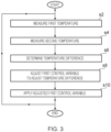
- Figure 3 is a process flow chart showing certain steps of an embodiment of a first control process implemented by the vacuum system 2 in operation.
- the first temperature sensor 24 measures a first temperature T 1 .
- the first temperature T 1 is a temperature of the exhaust fluid of the liquid ring pump 10 flowing in the exhaust line 38, i.e. the temperature of the air and water mixture being pumped by the liquid ring pump 10 to the separator 14.
- the first temperature T 1 measurement is sent by the first temperature sensor 24 to the controller 20 via the fifth connection 74.
- the second temperature sensor 32 measures a second temperature T 2 .
- the second temperature T 2 is a temperature of the operating liquid being received by the liquid ring pump 10 via the second operating liquid pipe 40.
- the second temperature T 2 measurement is sent by the second temperature sensor 32 to the controller 20 via the ninth connection 82.
- the controller 20 determines a temperature difference as the difference between the measured first temperature T 1 and the measured second temperature T 2 .
- the controller 20 acts to reduce or minimize the temperature difference ⁇ T by adjusting of a first control variable v 1 (t).
- the controller 20 attempts to equalise the temperature difference ⁇ T with a first threshold value, or to cause the temperature difference ⁇ T to be within a first threshold range (e.g. a first threshold value +/- a constant).
- the first threshold value may be any appropriate value, for example 1°C, 1.5°C, 2°C, 2.5°C, or 3°C.
- the first threshold value may be determined by testing, for example to determine a threshold value associated with high or optimum liquid ring pump efficiency.
- the first threshold value may be dependent on a size or power of the liquid ring pump 10.
- the first control variable v 1 (t) is an operating speed of the motor of the pump system 16.
- the controller 20 is a proportional-integral (PI) controller.
- the controller 20 applies correction/adjustment to the first control variable v 1 (t) based on proportional and integral terms of the temperature difference ⁇ T.
- the adjusted value of the first control variable v 1 (t) may be determined as a weighted sum of the control terms (i.e. of the proportional and integral parameters determined by the controller 20).
- the controller 20 increases the first control variable v 1 (t). (Increasing the first control variable v 1 (t) corresponds to speeding up the pump system 16).
- the controller 20 decreases the first control variable v 1 (t). (Decreasing the first control variable v 1 (t) corresponds to slowing down the pump system 16.)
- the controller 20 controls (using a VFD) the pump system 16 using the adjusted first control variable v 1 (t).
- the controller 20 generates a control signal for the motor pump system 16 based on the adjusted first control variable v 1 (t) determined at step s8. This control signal is then sent from the controller 20 to the pump system 16 via the second connection 68. The pump system 16 operates in accordance with the received control signal.
- the pump system 16 is sped up in accordance with the increased first control variable v 1 (t).
- the flow rate of relatively cool operating liquid into the liquid ring pump 10 is increased. This tends to cause a reduction in the first temperature T 1 measured by the first temperature sensor 24, thereby reducing the temperature difference ⁇ T.
- the pump system 16 is slowed down in accordance with the decreased first control variable v 1 (t).
- the flow rate of relatively cool operating liquid into the liquid ring pump 10 is decreased. This tends to cause an increase in the first temperature T 1 measured by the first temperature sensor 24, thereby increasing the temperature difference ⁇ T.
- step s10 the process of Figure 3 repeats, for example until the vacuum system 2 is shutdown.
- the process of Figure 3 may be performed continually, or more preferably continuously during operation of the vacuum system 2.
- the first control process comprises a control loop feedback mechanism in which continuously modulated control of the pump system 16 is performed.
- the above described system and first control process allows for the control of operating liquid temperature in a liquid ring pump.
- the above described system and first control process advantageously tends to reduce the likelihood of overloading the liquid ring pump with operating liquid. Furthermore, the likelihood and/or severity of hydraulic shock (also called “water hammer”) tends to be reduced. This tends to reduce damage to the liquid ring pump.
- the above described system and first control process tends to provide reduced or minimised operating liquid consumption. The operating liquid tends to be recycled in the above described system and first control process. This tends to reduce operating costs of the liquid ring pump.
- the above described system and first control process advantageously tends to reduce the likelihood and/or severity of cavitation occurring in the liquid ring pump.
- the pump system will tend to slow down.
- energy consumption tends to be reduced.
- the speed that the liquid ring pump 10 is running i.e. the speed that the motor 12 drives the liquid ring pump 10
- the speed that the liquid ring pump 10 is running can be limited by the so-called "anti-cavitation control" process which will now be described in more detail with reference to Figure 4 .
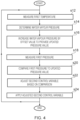
- Figure 4 is a process flow chart showing certain steps of a second control process not falling under the scope of the claims implemented by the vacuum system 2 in operation.
- the process of Figure 4 may be regarded as an "anti-cavitation control" process.
- the first temperature sensor 24 measures a first temperature T 1 .
- the first temperature T 1 is a temperature of the exhaust fluid of the liquid ring pump 10 flowing in the exhaust line 38, i.e. the temperature of the air and water mixture being pumped by the liquid ring pump 10 to the separator 14.
- the first temperature T 1 measurement is sent by the first temperature sensor 24 to the controller 20 via the fifth connection 74.
- the controller 20 determines or estimates the vapour pressure of the operating liquid in the liquid ring pump 10 using the measured first temperature T 1 .
- the operating liquid is water and, thus, the controller determines the vapour pressure of water for the first temperature T 1 , which is hereafter referred to as "the water vapour pressure P wv ".
- the water vapour pressure P wv is determined using an approximation formula, in particular the Antoine equation.
- one or more of the parameters A, m, and T n may have different value to that given above.
- the controller 20 adds a so-called offset value to the determined water vapour pressure P wv , thereby to determine an updated pressure value.
- the offset value P offset may be considered to be a safety margin.
- the offset value P offset may be any appropriate value including but not limited to a value between 1mbar and 10mbar, e.g. 1mbar, 2mbar, 3mbar, 4mbar, 5mbar, 6mbar, 7mbar, 8mbar, 9mbar, or 10mbar. In some embodiments, use of the offset value P offset is omitted.
- the first pressure sensor 22 measures a first pressure P 1 , the first pressure P 1 being the pressure of the gas flowing in the suction line 34, i.e. the pressure P 1 of the gas being pumped from the facility 4 by the action of the liquid ring pump 10.
- the first pressure P 1 measurement is sent by the first pressure sensor 22 to the controller 20 via the fourth connection 72.
- the controller 20 compares the measured first pressure P 1 to the determined updated pressure value P.
- the controller 20 determines an error value as the difference between the measured first pressure P 1 and the determined updated pressure value P.
- the controller 20 adjusts a second control variable v 2 (t) based on the comparison performed at step s20. For example, the controller 20 may act to increase the error value ⁇ P by adjusting a second control variable V2(t).
- the controller 20 may adjust the second control variable v 2 (t) to cause the error value ⁇ P to increase.
- the second control variable v 2 (t) is an operating speed of the motor 12.
- the controller 20 may adjust the second control variable v 2 (t) to cause an increase in the error value ⁇ P by adjusting or varying the second control variable v 2 (t) in a way that would cause a decrease in the operating speed of the motor 12. This reduction in operating speed of the motor 12 would tend to cause the liquid ring pump 10 to draw less gas from the facility 4 in a given time, which would tend to cause an increase in the pressure of the gas flowing in the suction line 34, i.e. the first pressure P 1 .
- the controller 20 is a proportional-integral (PI) controller.
- the controller 20 applies correction/adjustment to the second control variable v 2 (t) based on proportional and integral terms, e.g., of the error value ⁇ P.
- the adjusted value of the second control variable v 2 (t) may be determined as a weighted sum of the control terms (i.e. of the proportional and integral parameters determined by the controller 20).
- the controller 20 increases the second control variable v 2 (t). (Increasing the second control variable v 2 (t) corresponds to speeding up the motor 12 driving the liquid ring pump 10, which causes gas to be removed from the facility 4 more quickly, thereby decreasing the first pressure P 1 of the gas flowing in the suction line 34.)
- the controller 20 decreases the second control variable v 2 (t). (Decreasing the second control variable v 2 (t) corresponds to slowing down the motor 12 driving the liquid ring pump 10, which causes gas to be removed from the facility 4 less quickly, which may result in an increase in the first pressure P 1 of the gas flowing in the suction line 34.)
- the controller 20 controls the motor 12 using the adjusted second control variable v 2 (t).
- the controller 20 generates a control signal for the motor 12 based on the adjusted second control variable v 2 (t) determined at step s22. This control signal is then sent from the controller 20 to the motor 12 via the first connection 66. The motor 12 operates in accordance with the received control signal.
- the motor 12 is slowed down in accordance with the decreased second control variable v 2 (t).
- the operating speed of the liquid ring pump 10 is decreased resulting in a decrease of the flow rate of gas through the suction line 34 from the facility 4. This tends to cause an increase in the first pressure P 1 measured by the first pressure sensor 22, thereby increasing the error value ⁇ P.
- Increasing the error value ⁇ P means that the difference between the first pressure P 1 and the water vapour pressure P wv is increased. In other words, the pressure of the gas received by the liquid ring pump is moved away from the water vapour pressure P wv . This advantageously tends to reduce the likelihood of the inlet gas causing cavitation in the liquid ring pump 10.
- step s24 the process of Figure 4 repeats, for example until the vacuum system 2 is shutdown.
- the process of Figure 4 may be performed continually, or more preferably continuously during operation of the vacuum system 2.
- the second control process comprises a control loop feedback mechanism in which continuously modulated control of the motor 12 is performed.
- the above described system and second control process tends to allow for the control of fluid temperatures and pressures within a liquid ring pump.
- the above described system and second control process advantageously tends to reduce the likelihood and/or severity of cavitation occurring in the liquid ring pump.
- cavitation may be caused in the liquid ring pump by the inlet pressure (i.e. the pressure of gas from the suction line) being at or below the vapour pressure of the operating liquid in the liquid ring pump.
- the above described second control process advantageously tends to adjust the inlet pressure to move it away from vapour pressure of the operating liquid, thereby reducing the likelihood of cavitation.
- damage to the liquid ring pump caused by cavitation tends to be reduced or eliminated.
- the liquid ring pump is operated with variable speed drive (VSD).
- VSD variable speed drive
- the controller controls the liquid ring pump to vary the speed at which the liquid ring pump pumps gas from the facility.
- VSD variable speed drive
- the non-return valve advantageously tends to prevent or oppose this undesirable flow of gas, and is particularly beneficial for the liquid ring pump operated using VSD.
- the spray nozzle may be operated to vary the temperature of the operating liquid entering the liquid ring pump.
- the vacuum system comprises the elements described above with reference to Figure 1 .
- the vacuum system comprises the non-return valve, the spray nozzle, the liquid ring pump, the motor, the separator, the pump, the heat exchanger, the controller, the first and second pressure sensors, the first and second temperature sensors, and the first and second level sensors, and the connections therebetween.
- the vacuum system comprises other elements in addition to those described above.
- one or more of the non-return valve, the spray nozzle, the pressure sensors, and the level sensors may be omitted.
- multiple liquid ring pumps may be implemented.
- the heat exchanger cools the operating liquid flowing therethrough.
- other cooling means are implemented to cool the operating liquid prior to it being received by the liquid ring pump, instead of or in addition to the heat exchanger.
- a separator is implemented to recycle the operating liquid back into the liquid ring pump.
- a different type of recycling technique is implemented.
- the recycling of the operating liquid advantageously tends to reduce operating costs and water usage.
- recycling of the operating liquid is not performed.
- the vacuum system may include an open loop operating liquid circulation system in which fresh operating liquid is supplied to the liquid ring pump, and expelled operating liquid may be discarded.
- the separator may be omitted.
- the liquid ring pump is a single-stage liquid ring pump.
- the liquid ring pump is a different type of liquid ring pump, for example a multi-stage liquid ring pump.
- the operating liquid is water.
- the operating liquid is a different type of operating liquid.
- the controller is a PI controller.
- the controller is a different type of controller such as a proportional (P) controller, an integral (I) controller, a derivative (D) controller, a proportional-derivative controller (PD) controller, a proportional-integral-derivative controller (PID) controller, or a fuzzy logic controller.
- a single controller controls operation of multiple system elements (e.g. the motors).
- multiple controllers may be used, each controlling a respective subset of the group of elements.
- each motor may have a respective dedicated controller.
- the water vapour pressure in a different appropriate way, for example using a different approximation such as the August-Roche-Magnus (or Magnus-Tetens or Magnus) equation, the Tetens equation, the Buck equation, or the Goff-Gratch equation.
- the error value is determined in a different way, for example using a different appropriate formula.
- the error value may be a different function of the first pressure P 1 and/or the first temperature T 1 .
- weights may be applied to the measured pressure P 1 and/or the updated pressure value P.
- the pump is controlled to regulate or modulate flow of the operating liquid into the liquid ring pump.
- one or more different type of regulating device is implemented instead of or in addition to the pump, for example one or more valves for controlling a flow of operating fluid.
- the controller may be configured to control operation of the one or more regulating devices.
Landscapes
- Engineering & Computer Science (AREA)
- Mechanical Engineering (AREA)
- General Engineering & Computer Science (AREA)
- Physics & Mathematics (AREA)
- Fluid Mechanics (AREA)
- Control Of Positive-Displacement Pumps (AREA)
- Structures Of Non-Positive Displacement Pumps (AREA)
- Applications Or Details Of Rotary Compressors (AREA)
Claims (12)
- Flüssigkeitsringpumpen-Steuerungssystem, umfassend:eine Saugleitung (34);eine Auslassleitung (38);eine Betriebsflüssigkeitsleitung (40);eine Flüssigkeitsringpumpe (10), umfassend einen mit der Saugleitung (34) gekoppelten Saugeingang (108), einen mit der Auslassleitung (38) gekoppelten Auslassausgang und einen mit der Betriebsflüssigkeitsleitung (40) gekoppelten Flüssigkeitseingang;eine oder mehrere Regulierungsvorrichtungen (16), dazu ausgelegt, einen Strom von Betriebsflüssigkeit in die Flüssigkeitsringpumpe (10) zu steuern;einen ersten Sensor (24), dazu ausgelegt, einen ersten Parameter zu messen, wobei der erste Parameter eine Temperatur eines Auslassfluides der Flüssigkeitsringpumpe (10) ist;einen zweiten Sensor (32), dazu ausgelegt, einen zweiten Parameter zu messen, wobei derzweite Parameter eine Temperatur dervon der Flüssigkeitsringpumpe (10) über die Betriebsflüssigkeitsleitung (40) aufgenommenen Betriebsflüssigkeit ist; undeine Steuerung (20), operativ mit dem ersten Sensor (24), dem zweiten Sensor (32) und der einen oder mehreren Regulierungsvorrichtungen (16) gekoppelt und dazu ausgelegt:
eine Funktion des ersten und zweiten Parameters zu bestimmen, wobei die bestimmte Funktion lautet:
die eine oder mehrere Regulierungsvorrichtungen (16) auf Grundlage der bestimmten Funktion zu steuern. - Steuerungssystem nach Anspruch 1, wobei die eine oder mehrere Regulierungsvorrichtungen (16) eine Pumpe (16) umfassen, die dazu ausgelegt ist, die Betriebsflüssigkeit über die Betriebsflüssigkeitsleitung (40) zu der Flüssigkeitsringpumpe (10) zu pumpen.
- Steuerungssystem nach Anspruch 1 oder 2, wobei die Steuerung (20) dazu ausgelegt ist, eine Betriebsdrehzahl für die Pumpe (16) auf Grundlage von Sensormesswerten des ersten Sensors (24) und des zweiten Sensors (32) zu bestimmen und die Pumpe (16) entsprechend der bestimmten Betriebsdrehzahl zu steuern.
- Steuerungssystem nach einem der Ansprüche 1 bis 3, wobei die Saugleitung (34), die Auslassleitung (38) und die Betriebsflüssigkeitsleitung (40) separate, unabhängige Leitungen sind; und der Saugeingang (108), der Auslassausgang und der Flüssigkeitseingang separate Anschlüsse an der Flüssigkeitsringpumpe (10) sind.
- System nach einem der Ansprüche 1 bis 4, wobei die Steuerung (20) eine Steuerung ist, die aus der Gruppe von Steuerungen ausgewählt ist, die aus einer Proportionalsteuerung, einer Integralsteuerung, einer derivativen Steuerung, einer Proportional-IntegralSteuerung, einer Proportional-Integral-Derivativen Steuerung, einer Proportional-Derivativen Steuerung und einer Fuzzylogiksteuerung besteht.
- Steuerungssystem nach einem der Ansprüche 1 bis 5, ferner umfassend ein Betriebsflüssigkeitsrückführungssystem, dazu ausgelegt, Betriebsflüssigkeit in dem Auslassfluid der Flüssigkeitsringpumpe (10) in die Flüssigkeitsringpumpe (10) zurückzuführen.
- Steuerungssystem nach Anspruch 6, wobei das Betriebsflüssigkeitsrückführungssystem einen Abscheider (14) umfasst, dazu ausgelegt, Betriebsflüssigkeit aus dem Auslassfluid der Flüssigkeitsringpumpe (10) abzuscheiden.
- Steuerungssystem nach Anspruch 6 oder 7, wobei das
Betriebsflüssigkeitsrückführungssystem ein Kühlmittel (18) umfasst, dazu ausgelegt, die zurückgeführte Betriebsflüssigkeit zu kühlen, bevor die zurückgeführte Betriebsflüssigkeit von der Flüssigkeitsringpumpe (10) aufgenommen wird. - Steuerungssystem nach einem der Ansprüche 1 bis 8, ferner umfassend ein Rückschlagventil (6), angeordnet an der Saugleitung (34) und dazu ausgelegt, einen Fluidstrom in die Flüssigkeitsringpumpe (10) zuzulassen und einem Fluidstromstrom aus der Flüssigkeitsringpumpe (10) entgegenzuwirken.
- Steuerungssystem nach einem der Ansprüche 1 bis 9, ferner umfassend eine Sprühdüse (8), angeordnet an der Saugleitung (34) und dazu ausgelegt, Betriebsflüssigkeit aufzunehmen und die aufgenommene Betriebsflüssigkeit in die Saugleitung (34) zu sprühen.
- Steuerungssystem nach einem der Ansprüche 1 bis 10, ferner umfassend:einen Motor (12), dazu ausgelegt, die Flüssigkeitsringpumpe (10) anzutreiben; undeinen dritten Sensor (22), dazu ausgelegt, einen dritten Parameter zu messen, wobei der dritte Parameter ein Parameter von Gas ist, das von der Flüssigkeitsringpumpe (10) über die Saugleitung (34) aufgenommen wurde; wobeidie Steuerung (20) ferner operativ mit dem dritten Sensor (22) gekoppelt und dazu ausgelegt ist, den Motor (12) auf Grundlage von Sensormesswerten des ersten Sensors (24) und des dritten Sensors (22) zu steuern.
- Flüssigkeitsringpumpen-Steuerungsverfahren zum Steuern eines Systems, wobei das System umfasst: eine Saugleitung (34); eine Auslassleitung (38); eine Betriebsflüssigkeitsleitung (40); eine Flüssigkeitsringpumpe (10), umfassend einen mit der Saugleitung (40) gekoppelten Saugeingang (108), einen mit der Auslassleitung (38) gekoppelten Auslassausgang und einen mit der Betriebsflüssigkeitsleitung (40) gekoppelten Flüssigkeitseingang; und eine oder mehrere Regulierungsvorrichtungen (16), dazu ausgelegt, einen Strom der Betriebsflüssigkeit in die Flüssigkeitsringpumpe (10) zu steuern; wobei das Verfahren umfasst:Messen, durch einen ersten Sensor (24), eines ersten Parameters, wobei der erste Parameter eine Temperatur eines Auslassfluides der Flüssigkeitsringpumpe (10) ist;Messen, durch einen zweiten Sensor (32), eines zweiten Parameters, wobei der zweite Parameter eine Temperatur einer von der Flüssigkeitsringpumpe (10) über die Betriebsflüssigkeitsleitung (40) aufgenommenen Betriebsflüssigkeit ist; undBestimmen, durch eine Steuerung (20), die operativ mit dem ersten Sensor (24), dem zweiten Sensor (32) und der einen oder mehreren Regulierungsvorrichtungen (16) gekoppelt ist, einer Funktion des ersten und zweiten Parameters, wobei die bestimmte Funktion lautet:

Steuern, durch die Steuerung (20), der einen oder mehrerer Regulierungsvorrichtungen (16) auf Grundlage der bestimmten Funktion.
Applications Claiming Priority (2)
| Application Number | Priority Date | Filing Date | Title |
|---|---|---|---|
| GB1804108.7A GB2571971B (en) | 2018-03-14 | 2018-03-14 | Liquid ring pump control |
| PCT/IB2019/052066 WO2019175819A1 (en) | 2018-03-14 | 2019-03-14 | Liquid ring pump control |
Publications (3)
| Publication Number | Publication Date |
|---|---|
| EP3765745A1 EP3765745A1 (de) | 2021-01-20 |
| EP3765745A4 EP3765745A4 (de) | 2021-09-08 |
| EP3765745B1 true EP3765745B1 (de) | 2024-08-07 |
Family
ID=61972921
Family Applications (2)
| Application Number | Title | Priority Date | Filing Date |
|---|---|---|---|
| EP19767577.0A Active EP3765741B1 (de) | 2018-03-14 | 2019-03-14 | Steuersystem für flüssigkeitsringpumpen |
| EP19768178.6A Active EP3765745B1 (de) | 2018-03-14 | 2019-03-14 | Steuerung einer flüssigkeitsringpumpe |
Family Applications Before (1)
| Application Number | Title | Priority Date | Filing Date |
|---|---|---|---|
| EP19767577.0A Active EP3765741B1 (de) | 2018-03-14 | 2019-03-14 | Steuersystem für flüssigkeitsringpumpen |
Country Status (5)
| Country | Link |
|---|---|
| US (2) | US20210025391A1 (de) |
| EP (2) | EP3765741B1 (de) |
| CN (2) | CN112005015B (de) |
| GB (2) | GB2571971B (de) |
| WO (2) | WO2019175819A1 (de) |
Families Citing this family (9)
| Publication number | Priority date | Publication date | Assignee | Title |
|---|---|---|---|---|
| KR20210079329A (ko) * | 2018-10-25 | 2021-06-29 | 에드워즈 테크놀로지스 배큠 엔지니어링 (칭다오) 컴퍼니 리미티드 | 세퍼레이터 시스템 |
| GB2596366B (en) * | 2020-06-26 | 2022-11-09 | Edwards Tech Vacuum Engineering Qingdao Co Ltd | Liquid ring pump control |
| CN112128109A (zh) * | 2020-08-24 | 2020-12-25 | 浙江飞越机电有限公司 | 根据泵温识别工况的结构及识别方法 |
| WO2022041106A1 (en) | 2020-08-28 | 2022-03-03 | Edwards Technologies Vacuum Engineering (Qingdao) Co Ltd | Control of operating liquid flow into a liquid ring pump |
| GB2598418B (en) * | 2020-09-22 | 2022-10-12 | Edwards Tech Vacuum Engineering Qingdao Company Limited | Control of operating liquid flow into a liquid ring pump |
| CN113627099B (zh) * | 2021-08-02 | 2024-03-26 | 浙江理工大学 | 一种预测空化流场的方法及装置 |
| CN114278575B (zh) * | 2021-12-28 | 2023-05-30 | 中国航空工业集团公司金城南京机电液压工程研究中心 | 一种具有智能排气功能的离心泵 |
| GB2615836A (en) | 2022-02-17 | 2023-08-23 | Edwards Tech Vacuum Engineering Qingdao Company Limited | System and method for cleaning a liquid ring pump system |
| CN116123083B (zh) * | 2022-09-08 | 2026-01-02 | 奇瑞汽车股份有限公司 | 泵装置 |
Family Cites Families (29)
| Publication number | Priority date | Publication date | Assignee | Title |
|---|---|---|---|---|
| US4087208A (en) | 1976-06-08 | 1978-05-02 | Mitsubishi Jukogyo Kabushiki Kaisha | Method for compressing mixed gas consisting of combustible gas and air |
| US4315717A (en) * | 1979-11-19 | 1982-02-16 | The Nash Engineering Company | Evacuation system with precondenser |
| DE3204784A1 (de) * | 1982-02-11 | 1983-08-25 | Siemens AG, 1000 Berlin und 8000 München | Fluessigkeitsringvakuumpumpe mit vorgeschaltetem vorverdichter |
| DE3420144A1 (de) * | 1984-05-30 | 1985-12-05 | Loewe Pumpenfabrik GmbH, 2120 Lüneburg | Regelungs- und steuerungssystem, insbes. fuer wassering-vakuumpumpen |
| US4699570A (en) * | 1986-03-07 | 1987-10-13 | Itt Industries, Inc | Vacuum pump system |
| EP0437637A1 (de) | 1989-11-20 | 1991-07-24 | KKW Kulmbacher Klimageräte-Werk GmbH | Flüssigkeitsringpumpe |
| JPH041499A (ja) * | 1990-04-13 | 1992-01-06 | Toshiba Corp | ポンプの吐出流量制御装置 |
| JP3957371B2 (ja) * | 1997-09-03 | 2007-08-15 | 株式会社大阪真空機器製作所 | 真空装置及びその運転方法 |
| EP0943805B1 (de) | 1998-03-19 | 2004-12-15 | NSB Gas Processing AG | Verfahren und Sensor zur Detektion von Kavitationen, sowie Vorrichtung enthaltend einen solchen Sensor |
| US7871249B2 (en) | 1998-04-16 | 2011-01-18 | Air Liquide Electronics U.S. Lp | Systems and methods for managing fluids using a liquid ring pump |
| US6227222B1 (en) * | 2000-01-05 | 2001-05-08 | Fluid Compressor Corp. | Closed oil liquid ring gas compression system with a suction injection port |
| US6558131B1 (en) * | 2001-06-29 | 2003-05-06 | nash-elmo industries, l.l.c. | Liquid ring pumps with automatic control of seal liquid injection |
| WO2004041727A1 (en) * | 2002-11-08 | 2004-05-21 | H2O Holdings Pty Ltd | A distillation unit and a method of distillation |
| US7927080B2 (en) | 2004-09-17 | 2011-04-19 | Basf Aktiengesellschaft | Method for operating a liquid ring compressor |
| DE102005043434A1 (de) * | 2005-09-13 | 2007-03-15 | Gardner Denver Elmo Technology Gmbh | Einrichtung zur Leistungsanpassung einer Flüssigkeitsringpumpe |
| DK2427632T3 (en) * | 2009-05-06 | 2017-04-03 | Curtiss-Wright Electro-Mechanical Corp | Gas-resistant underwater pump |
| US8657584B2 (en) * | 2010-02-16 | 2014-02-25 | Edwards Limited | Apparatus and method for tuning pump speed |
| CN102062088B (zh) * | 2011-01-19 | 2012-11-28 | 西安交通大学 | 一种适应用高含气率工况的双螺杆混输泵装置 |
| DE102012000980A1 (de) | 2012-01-20 | 2013-07-25 | Ecotecfuel Llc | Verfahren und Vorrichtung zur mechanischen Aufheizung eines Stoffgemisches |
| US10047747B2 (en) * | 2013-01-21 | 2018-08-14 | Sterling Industry Consult Gmbh | Pump assembly and method for evacuating a vapor-filled chamber |
| JP6331078B2 (ja) | 2014-04-16 | 2018-05-30 | 三浦工業株式会社 | 水封式真空ポンプを用いた減圧装置 |
| DK178041B1 (da) * | 2014-06-25 | 2015-04-07 | Hvidtved Larsen As J | Mobil slamsuger samt fremgangsmåde |
| CN204900220U (zh) * | 2015-08-21 | 2015-12-23 | 广东肯富来泵业股份有限公司 | 一种液环泵运行实时监测系统 |
| CN205172949U (zh) * | 2015-11-12 | 2016-04-20 | 湖北同方高科泵业有限公司 | 一种双级锥体液环泵抽真空成套装置 |
| CN105782058B (zh) | 2016-04-22 | 2018-09-25 | 中国电力工程顾问集团中南电力设计院有限公司 | 一种液环式真空泵回水系统及回水方法 |
| CN106089716A (zh) | 2016-08-22 | 2016-11-09 | 成都超迈光电科技有限公司 | 一种耐腐防爆环保型液环真空机组 |
| US20180245594A1 (en) * | 2017-02-24 | 2018-08-30 | Gardner Denver Nash Llc | Pump system including a controller |
| CN107242432A (zh) * | 2017-07-18 | 2017-10-13 | 天津商业大学 | 一种可调节真空度的熟食品真空冷却设备 |
| CN107723417B (zh) * | 2017-08-21 | 2019-07-05 | 中冶南方工程技术有限公司 | 抽真空系统及其使用方法、真空精炼系统 |
-
2018
- 2018-03-14 GB GB1804108.7A patent/GB2571971B/en not_active Expired - Fee Related
- 2018-12-20 GB GB1820866.0A patent/GB2572035B/en active Active
-
2019
- 2019-03-14 WO PCT/IB2019/052066 patent/WO2019175819A1/en not_active Ceased
- 2019-03-14 EP EP19767577.0A patent/EP3765741B1/de active Active
- 2019-03-14 EP EP19768178.6A patent/EP3765745B1/de active Active
- 2019-03-14 CN CN201980019109.0A patent/CN112005015B/zh active Active
- 2019-03-14 US US16/980,484 patent/US20210025391A1/en not_active Abandoned
- 2019-03-14 CN CN201980019124.5A patent/CN112020611B/zh active Active
- 2019-03-14 WO PCT/IB2019/052072 patent/WO2019175823A1/en not_active Ceased
- 2019-03-14 US US16/979,852 patent/US11746785B2/en active Active
Also Published As
| Publication number | Publication date |
|---|---|
| GB2571971A (en) | 2019-09-18 |
| CN112005015B (zh) | 2023-08-04 |
| CN112005015A (zh) | 2020-11-27 |
| EP3765741B1 (de) | 2026-03-11 |
| GB2572035A (en) | 2019-09-18 |
| EP3765741A4 (de) | 2022-01-19 |
| CN112020611B (zh) | 2023-04-11 |
| US11746785B2 (en) | 2023-09-05 |
| WO2019175823A1 (en) | 2019-09-19 |
| EP3765745A4 (de) | 2021-09-08 |
| EP3765741A1 (de) | 2021-01-20 |
| GB201820866D0 (en) | 2019-02-06 |
| US20210025391A1 (en) | 2021-01-28 |
| CN112020611A (zh) | 2020-12-01 |
| WO2019175819A1 (en) | 2019-09-19 |
| GB2572035B (en) | 2021-07-14 |
| US20210364003A1 (en) | 2021-11-25 |
| GB2571971B (en) | 2020-09-23 |
| GB201804108D0 (en) | 2018-04-25 |
| EP3765745A1 (de) | 2021-01-20 |
Similar Documents
| Publication | Publication Date | Title |
|---|---|---|
| EP3765745B1 (de) | Steuerung einer flüssigkeitsringpumpe | |
| EP3765744B1 (de) | Steuerung einer flüssigkeitsringpumpe | |
| US12123412B2 (en) | Control of operating liquid flow into a liquid ring pump | |
| EP4172503B1 (de) | Flüssigkeitsringpumpensteuerung | |
| EP3765743B1 (de) | Steuerung einer flüssigkeitsringpumpe | |
| US12188473B2 (en) | Control of liquid ring pump | |
| GB2598418A (en) | Control of operating liquid flow into liquid ring pump | |
| EP4295048B1 (de) | Steuerung einer flüssigkeitsringpumpe | |
| US20240004377A1 (en) | A pump monitoring system and method for associating a current operating state of a pump system with one or more fault scenarios |
Legal Events
| Date | Code | Title | Description |
|---|---|---|---|
| STAA | Information on the status of an ep patent application or granted ep patent |
Free format text: STATUS: THE INTERNATIONAL PUBLICATION HAS BEEN MADE |
|
| PUAI | Public reference made under article 153(3) epc to a published international application that has entered the european phase |
Free format text: ORIGINAL CODE: 0009012 |
|
| STAA | Information on the status of an ep patent application or granted ep patent |
Free format text: STATUS: REQUEST FOR EXAMINATION WAS MADE |
|
| 17P | Request for examination filed |
Effective date: 20200928 |
|
| AK | Designated contracting states |
Kind code of ref document: A1 Designated state(s): AL AT BE BG CH CY CZ DE DK EE ES FI FR GB GR HR HU IE IS IT LI LT LU LV MC MK MT NL NO PL PT RO RS SE SI SK SM TR |
|
| AX | Request for extension of the european patent |
Extension state: BA ME |
|
| DAV | Request for validation of the european patent (deleted) | ||
| DAX | Request for extension of the european patent (deleted) | ||
| A4 | Supplementary search report drawn up and despatched |
Effective date: 20210806 |
|
| RIC1 | Information provided on ipc code assigned before grant |
Ipc: F04C 28/24 20060101ALI20210802BHEP Ipc: F04C 28/28 20060101ALI20210802BHEP Ipc: F04C 27/02 20060101ALI20210802BHEP Ipc: F04C 28/08 20060101ALI20210802BHEP Ipc: F04C 19/00 20060101ALI20210802BHEP Ipc: F04C 25/02 20060101AFI20210802BHEP |
|
| GRAP | Despatch of communication of intention to grant a patent |
Free format text: ORIGINAL CODE: EPIDOSNIGR1 |
|
| STAA | Information on the status of an ep patent application or granted ep patent |
Free format text: STATUS: GRANT OF PATENT IS INTENDED |
|
| INTG | Intention to grant announced |
Effective date: 20240306 |
|
| GRAS | Grant fee paid |
Free format text: ORIGINAL CODE: EPIDOSNIGR3 |
|
| GRAA | (expected) grant |
Free format text: ORIGINAL CODE: 0009210 |
|
| STAA | Information on the status of an ep patent application or granted ep patent |
Free format text: STATUS: THE PATENT HAS BEEN GRANTED |
|
| P01 | Opt-out of the competence of the unified patent court (upc) registered |
Free format text: CASE NUMBER: APP_37561/2024 Effective date: 20240624 |
|
| AK | Designated contracting states |
Kind code of ref document: B1 Designated state(s): AL AT BE BG CH CY CZ DE DK EE ES FI FR GB GR HR HU IE IS IT LI LT LU LV MC MK MT NL NO PL PT RO RS SE SI SK SM TR |
|
| REG | Reference to a national code |
Ref country code: GB Ref legal event code: FG4D |
|
| REG | Reference to a national code |
Ref country code: CH Ref legal event code: EP |
|
| REG | Reference to a national code |
Ref country code: IE Ref legal event code: FG4D |
|
| REG | Reference to a national code |
Ref country code: DE Ref legal event code: R096 Ref document number: 602019056616 Country of ref document: DE |
|
| REG | Reference to a national code |
Ref country code: LT Ref legal event code: MG9D |
|
| REG | Reference to a national code |
Ref country code: NL Ref legal event code: MP Effective date: 20240807 |
|
| PG25 | Lapsed in a contracting state [announced via postgrant information from national office to epo] |
Ref country code: NO Free format text: LAPSE BECAUSE OF FAILURE TO SUBMIT A TRANSLATION OF THE DESCRIPTION OR TO PAY THE FEE WITHIN THE PRESCRIBED TIME-LIMIT Effective date: 20241107 |
|
| REG | Reference to a national code |
Ref country code: AT Ref legal event code: MK05 Ref document number: 1711205 Country of ref document: AT Kind code of ref document: T Effective date: 20240807 |
|
| PG25 | Lapsed in a contracting state [announced via postgrant information from national office to epo] |
Ref country code: FI Free format text: LAPSE BECAUSE OF FAILURE TO SUBMIT A TRANSLATION OF THE DESCRIPTION OR TO PAY THE FEE WITHIN THE PRESCRIBED TIME-LIMIT Effective date: 20240807 Ref country code: NL Free format text: LAPSE BECAUSE OF FAILURE TO SUBMIT A TRANSLATION OF THE DESCRIPTION OR TO PAY THE FEE WITHIN THE PRESCRIBED TIME-LIMIT Effective date: 20240807 Ref country code: PL Free format text: LAPSE BECAUSE OF FAILURE TO SUBMIT A TRANSLATION OF THE DESCRIPTION OR TO PAY THE FEE WITHIN THE PRESCRIBED TIME-LIMIT Effective date: 20240807 Ref country code: PT Free format text: LAPSE BECAUSE OF FAILURE TO SUBMIT A TRANSLATION OF THE DESCRIPTION OR TO PAY THE FEE WITHIN THE PRESCRIBED TIME-LIMIT Effective date: 20241209 Ref country code: GR Free format text: LAPSE BECAUSE OF FAILURE TO SUBMIT A TRANSLATION OF THE DESCRIPTION OR TO PAY THE FEE WITHIN THE PRESCRIBED TIME-LIMIT Effective date: 20241108 |
|
| PG25 | Lapsed in a contracting state [announced via postgrant information from national office to epo] |
Ref country code: BG Free format text: LAPSE BECAUSE OF FAILURE TO SUBMIT A TRANSLATION OF THE DESCRIPTION OR TO PAY THE FEE WITHIN THE PRESCRIBED TIME-LIMIT Effective date: 20240807 |
|
| PG25 | Lapsed in a contracting state [announced via postgrant information from national office to epo] |
Ref country code: LV Free format text: LAPSE BECAUSE OF FAILURE TO SUBMIT A TRANSLATION OF THE DESCRIPTION OR TO PAY THE FEE WITHIN THE PRESCRIBED TIME-LIMIT Effective date: 20240807 |
|
| PG25 | Lapsed in a contracting state [announced via postgrant information from national office to epo] |
Ref country code: AT Free format text: LAPSE BECAUSE OF FAILURE TO SUBMIT A TRANSLATION OF THE DESCRIPTION OR TO PAY THE FEE WITHIN THE PRESCRIBED TIME-LIMIT Effective date: 20240807 Ref country code: IS Free format text: LAPSE BECAUSE OF FAILURE TO SUBMIT A TRANSLATION OF THE DESCRIPTION OR TO PAY THE FEE WITHIN THE PRESCRIBED TIME-LIMIT Effective date: 20241207 |
|
| PG25 | Lapsed in a contracting state [announced via postgrant information from national office to epo] |
Ref country code: HR Free format text: LAPSE BECAUSE OF FAILURE TO SUBMIT A TRANSLATION OF THE DESCRIPTION OR TO PAY THE FEE WITHIN THE PRESCRIBED TIME-LIMIT Effective date: 20240807 |
|
| PG25 | Lapsed in a contracting state [announced via postgrant information from national office to epo] |
Ref country code: ES Free format text: LAPSE BECAUSE OF FAILURE TO SUBMIT A TRANSLATION OF THE DESCRIPTION OR TO PAY THE FEE WITHIN THE PRESCRIBED TIME-LIMIT Effective date: 20240807 Ref country code: RS Free format text: LAPSE BECAUSE OF FAILURE TO SUBMIT A TRANSLATION OF THE DESCRIPTION OR TO PAY THE FEE WITHIN THE PRESCRIBED TIME-LIMIT Effective date: 20241107 |
|
| PG25 | Lapsed in a contracting state [announced via postgrant information from national office to epo] |
Ref country code: RS Free format text: LAPSE BECAUSE OF FAILURE TO SUBMIT A TRANSLATION OF THE DESCRIPTION OR TO PAY THE FEE WITHIN THE PRESCRIBED TIME-LIMIT Effective date: 20241107 Ref country code: PT Free format text: LAPSE BECAUSE OF FAILURE TO SUBMIT A TRANSLATION OF THE DESCRIPTION OR TO PAY THE FEE WITHIN THE PRESCRIBED TIME-LIMIT Effective date: 20241209 Ref country code: PL Free format text: LAPSE BECAUSE OF FAILURE TO SUBMIT A TRANSLATION OF THE DESCRIPTION OR TO PAY THE FEE WITHIN THE PRESCRIBED TIME-LIMIT Effective date: 20240807 Ref country code: NO Free format text: LAPSE BECAUSE OF FAILURE TO SUBMIT A TRANSLATION OF THE DESCRIPTION OR TO PAY THE FEE WITHIN THE PRESCRIBED TIME-LIMIT Effective date: 20241107 Ref country code: NL Free format text: LAPSE BECAUSE OF FAILURE TO SUBMIT A TRANSLATION OF THE DESCRIPTION OR TO PAY THE FEE WITHIN THE PRESCRIBED TIME-LIMIT Effective date: 20240807 Ref country code: LV Free format text: LAPSE BECAUSE OF FAILURE TO SUBMIT A TRANSLATION OF THE DESCRIPTION OR TO PAY THE FEE WITHIN THE PRESCRIBED TIME-LIMIT Effective date: 20240807 Ref country code: IS Free format text: LAPSE BECAUSE OF FAILURE TO SUBMIT A TRANSLATION OF THE DESCRIPTION OR TO PAY THE FEE WITHIN THE PRESCRIBED TIME-LIMIT Effective date: 20241207 Ref country code: HR Free format text: LAPSE BECAUSE OF FAILURE TO SUBMIT A TRANSLATION OF THE DESCRIPTION OR TO PAY THE FEE WITHIN THE PRESCRIBED TIME-LIMIT Effective date: 20240807 Ref country code: GR Free format text: LAPSE BECAUSE OF FAILURE TO SUBMIT A TRANSLATION OF THE DESCRIPTION OR TO PAY THE FEE WITHIN THE PRESCRIBED TIME-LIMIT Effective date: 20241108 Ref country code: FI Free format text: LAPSE BECAUSE OF FAILURE TO SUBMIT A TRANSLATION OF THE DESCRIPTION OR TO PAY THE FEE WITHIN THE PRESCRIBED TIME-LIMIT Effective date: 20240807 Ref country code: ES Free format text: LAPSE BECAUSE OF FAILURE TO SUBMIT A TRANSLATION OF THE DESCRIPTION OR TO PAY THE FEE WITHIN THE PRESCRIBED TIME-LIMIT Effective date: 20240807 Ref country code: BG Free format text: LAPSE BECAUSE OF FAILURE TO SUBMIT A TRANSLATION OF THE DESCRIPTION OR TO PAY THE FEE WITHIN THE PRESCRIBED TIME-LIMIT Effective date: 20240807 Ref country code: AT Free format text: LAPSE BECAUSE OF FAILURE TO SUBMIT A TRANSLATION OF THE DESCRIPTION OR TO PAY THE FEE WITHIN THE PRESCRIBED TIME-LIMIT Effective date: 20240807 |
|
| PG25 | Lapsed in a contracting state [announced via postgrant information from national office to epo] |
Ref country code: SM Free format text: LAPSE BECAUSE OF FAILURE TO SUBMIT A TRANSLATION OF THE DESCRIPTION OR TO PAY THE FEE WITHIN THE PRESCRIBED TIME-LIMIT Effective date: 20240807 Ref country code: DK Free format text: LAPSE BECAUSE OF FAILURE TO SUBMIT A TRANSLATION OF THE DESCRIPTION OR TO PAY THE FEE WITHIN THE PRESCRIBED TIME-LIMIT Effective date: 20240807 Ref country code: RO Free format text: LAPSE BECAUSE OF FAILURE TO SUBMIT A TRANSLATION OF THE DESCRIPTION OR TO PAY THE FEE WITHIN THE PRESCRIBED TIME-LIMIT Effective date: 20240807 |
|
| PG25 | Lapsed in a contracting state [announced via postgrant information from national office to epo] |
Ref country code: EE Free format text: LAPSE BECAUSE OF FAILURE TO SUBMIT A TRANSLATION OF THE DESCRIPTION OR TO PAY THE FEE WITHIN THE PRESCRIBED TIME-LIMIT Effective date: 20240807 |
|
| PG25 | Lapsed in a contracting state [announced via postgrant information from national office to epo] |
Ref country code: CZ Free format text: LAPSE BECAUSE OF FAILURE TO SUBMIT A TRANSLATION OF THE DESCRIPTION OR TO PAY THE FEE WITHIN THE PRESCRIBED TIME-LIMIT Effective date: 20240807 |
|
| PG25 | Lapsed in a contracting state [announced via postgrant information from national office to epo] |
Ref country code: SK Free format text: LAPSE BECAUSE OF FAILURE TO SUBMIT A TRANSLATION OF THE DESCRIPTION OR TO PAY THE FEE WITHIN THE PRESCRIBED TIME-LIMIT Effective date: 20240807 |
|
| REG | Reference to a national code |
Ref country code: DE Ref legal event code: R097 Ref document number: 602019056616 Country of ref document: DE |
|
| PLBE | No opposition filed within time limit |
Free format text: ORIGINAL CODE: 0009261 |
|
| STAA | Information on the status of an ep patent application or granted ep patent |
Free format text: STATUS: NO OPPOSITION FILED WITHIN TIME LIMIT |
|
| 26N | No opposition filed |
Effective date: 20250508 |
|
| PG25 | Lapsed in a contracting state [announced via postgrant information from national office to epo] |
Ref country code: SE Free format text: LAPSE BECAUSE OF FAILURE TO SUBMIT A TRANSLATION OF THE DESCRIPTION OR TO PAY THE FEE WITHIN THE PRESCRIBED TIME-LIMIT Effective date: 20240807 |
|
| PG25 | Lapsed in a contracting state [announced via postgrant information from national office to epo] |
Ref country code: MC Free format text: LAPSE BECAUSE OF FAILURE TO SUBMIT A TRANSLATION OF THE DESCRIPTION OR TO PAY THE FEE WITHIN THE PRESCRIBED TIME-LIMIT Effective date: 20240807 |
|
| REG | Reference to a national code |
Ref country code: CH Ref legal event code: H13 Free format text: ST27 STATUS EVENT CODE: U-0-0-H10-H13 (AS PROVIDED BY THE NATIONAL OFFICE) Effective date: 20251023 |
|
| PG25 | Lapsed in a contracting state [announced via postgrant information from national office to epo] |
Ref country code: LU Free format text: LAPSE BECAUSE OF NON-PAYMENT OF DUE FEES Effective date: 20250314 |
|
| REG | Reference to a national code |
Ref country code: BE Ref legal event code: MM Effective date: 20250331 |
|
| PG25 | Lapsed in a contracting state [announced via postgrant information from national office to epo] |
Ref country code: IT Free format text: LAPSE BECAUSE OF NON-PAYMENT OF DUE FEES Effective date: 20250314 |
|
| PG25 | Lapsed in a contracting state [announced via postgrant information from national office to epo] |
Ref country code: BE Free format text: LAPSE BECAUSE OF NON-PAYMENT OF DUE FEES Effective date: 20250331 |
|
| PG25 | Lapsed in a contracting state [announced via postgrant information from national office to epo] |
Ref country code: CH Free format text: LAPSE BECAUSE OF NON-PAYMENT OF DUE FEES Effective date: 20250331 |
|
| PG25 | Lapsed in a contracting state [announced via postgrant information from national office to epo] |
Ref country code: IE Free format text: LAPSE BECAUSE OF NON-PAYMENT OF DUE FEES Effective date: 20250314 |
|
| PGFP | Annual fee paid to national office [announced via postgrant information from national office to epo] |
Ref country code: GB Payment date: 20260327 Year of fee payment: 8 |
|
| PGFP | Annual fee paid to national office [announced via postgrant information from national office to epo] |
Ref country code: DE Payment date: 20260327 Year of fee payment: 8 |
|
| PG25 | Lapsed in a contracting state [announced via postgrant information from national office to epo] |
Ref country code: IT Free format text: LAPSE BECAUSE OF NON-PAYMENT OF DUE FEES Effective date: 20250314 |
|
| PGFP | Annual fee paid to national office [announced via postgrant information from national office to epo] |
Ref country code: IT Payment date: 20260319 Year of fee payment: 8 |
|
| PGRI | Patent reinstated in contracting state [announced from national office to epo] |
Ref country code: IT Effective date: 20250731 |
|
| PGFP | Annual fee paid to national office [announced via postgrant information from national office to epo] |
Ref country code: FR Payment date: 20260325 Year of fee payment: 8 |
|
| PGFP | Annual fee paid to national office [announced via postgrant information from national office to epo] |
Ref country code: TR Payment date: 20260220 Year of fee payment: 8 |