EP3766151B1 - Armoire électrique - Google Patents
Armoire électrique Download PDFInfo
- Publication number
- EP3766151B1 EP3766151B1 EP19716570.7A EP19716570A EP3766151B1 EP 3766151 B1 EP3766151 B1 EP 3766151B1 EP 19716570 A EP19716570 A EP 19716570A EP 3766151 B1 EP3766151 B1 EP 3766151B1
- Authority
- EP
- European Patent Office
- Prior art keywords
- display
- configuration
- door
- cabinet
- work configuration
- Prior art date
- Legal status (The legal status is an assumption and is not a legal conclusion. Google has not performed a legal analysis and makes no representation as to the accuracy of the status listed.)
- Active
Links
Images




Classifications
-
- H—ELECTRICITY
- H02—GENERATION; CONVERSION OR DISTRIBUTION OF ELECTRIC POWER
- H02B—BOARDS, SUBSTATIONS OR SWITCHING ARRANGEMENTS FOR THE SUPPLY OR DISTRIBUTION OF ELECTRIC POWER
- H02B1/00—Frameworks, boards, panels, desks, casings; Details of substations or switching arrangements
- H02B1/26—Casings; Parts thereof or accessories therefor
- H02B1/30—Cabinet-type casings; Parts thereof or accessories therefor
- H02B1/306—Accessories, e.g. windows
Definitions
- the present invention relates to a cabinet for electrical apparatuses.
- Cabinets of known type generally comprise a substantially closed supporting frame inside which one or more electrical apparatuses are arranged, like for instance an UPS used with the aim of keeping one or more electronic devices electrically powered at all times even in the event of a power failure.
- UPS electrical apparatuses
- UPSs are particularly important where there are electrical apparatuses the sudden turning off of which would cause serious consequences, e.g. in operating theatres or in data centers.
- the UPSs contained inside cabinets of this type generally comprise one or more power supply units necessary to power one or more electronic devices.
- Cabinets of this type also comprise an access door which is hinged to the supporting frame so that they can be opened and closed, so as to make it easier to install the power supply units inside the supporting frame itself.
- the power supply units generally comprise at least one control unit, at least one electric charge accumulator and at least one power electronics unit connected to each other.
- each of these components must be correctly installed and configured to ensure the correct power supply of one or more electronic devices in the event of a power failure.
- the cabinets of known type are provided with a monitoring and configuration front display which is operatively connected to the power supply units located inside the supporting frame.
- the cabinets of this type do however have some drawbacks related to the installation, replacement and maintenance operations to be carried out of the power supply units contained inside the supporting frame.
- the aforementioned information is to be deemed valid also for the maintenance operations that must be carried out periodically on the uninterruptible power systems to ensure the correct operation thereof, or also for the repair or replacement operations of one or more power supply units.
- the main aim of the present invention is to devise a cabinet for electrical apparatuses which allows making easy and fast the operations of installation, configuration and maintenance/repair of the power supply units.
- Another object of the present invention is to devise a cabinet for electrical apparatuses that allows overcoming the mentioned drawbacks of the prior art in a simple, rational, easy, effective to use and cost effective solution.
- reference numeral 1 globally indicates a cabinet for electrical apparatuses.
- the cabinet 1 for electrical apparatuses comprises:
- electrical is also used to refer to electronic components or electrical components made at least in part from electronic elements.
- the supporting frame 2 is preferably of the type of a cabinet positioned resting on the ground and openable and closable manually by an operator by means of the door 4.
- the words "outer” and “inner” used with reference to the faces 5, 6 of the door 4 are intended to indicate the face of the door 4 which is accessible to the operator when the door 4 closes the compartment 3, and the face of the door 4 which is substantially facing the compartment 3 and which is inaccessible to the operator when the door 4 closes the compartment 3, respectively.
- the display 8 preferably has a substantially flat shape and comprises a screen 10 of the touch-screen type and a connecting panel 11 substantially opposed to the screen 10 and adapted to operatively connect the display 8 to the electrical apparatus 7.
- the electrical apparatus 7 is an uninterruptible power system for the supply of at least one electronic device comprising at least one power supply unit provided with:
- the cabinet 1 cannot however be ruled out, e.g. wherein the cabinet 1 contains at least one electrical apparatus 7 of the generic type housed inside the compartment 3 and connected to the display 8 so as to monitor the operation thereof.
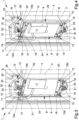
- the cabinet 1 comprises at least one access opening 9 to the display 8 made on the door 4, the access opening 9 being completely closed by the display 8 in the first work configuration, as shown in Figure 1 .
- the access opening 9 is made with a shape substantially complementary with respect to that of the display 8 so as to make the screen 10 fully accessible through the access opening 9.
- the display 8 and the access opening 9 are substantially rectangular in shape.
- the cabinet 1 cannot however be ruled out, wherein the display 8 and the access opening 9 are made of different shapes, such as e.g. square shapes.
- the cabinet 1 comprises orientation means 25, 26 for orienting the display 8 between a first work configuration, in which the display 8 is facing from the outer face 6 and is accessible when the door 4 is closed, and at least a second work configuration, in which the display 8 is arranged facing from the inner face 5 and is accessible when the door 4 is open.
- the orientation means 25, 26 are preferably associated with the inner face 5 of the door 4.
- orientation means 25, 26 comprise rotation means for rotating the display 8 around at least one axis of rotation A between the first work configuration and the second work configuration.
- the axis of rotation A is arranged substantially vertical to the ground.
- the rotation means 25, 26 comprise supporting means 26 associated with the door 4 and at least one moveable assembly 25 associated rotating around the axis of rotation A with the supporting means 26, the display 8 being locked together in rotation to the moveable assembly 25.
- the supporting means 26 comprise at least one pair of fixed bodies 12 substantially opposed to each other, the moveable assembly 25 being interposed between the pair of fixed bodies 12.
- the fixed bodies 12 are brackets fixed to the inner face 5 one below the other in the proximity of an upper end and a lower end of the access opening 9 respectively, as shown in Figures 3 to 6 .
- the words “upper” and “lower”, as well as the words “above” and “below”, used with reference to the components of the cabinet 1 are meant to indicate the level with respect to the ground at which these components are arranged one with respect to the other.
- the fixed bodies 12 comprise one holding element 13 of substantially flat shape, arranged substantially horizontal to the ground and protruding from the door 4.
- the holding elements 13 of the two fixed bodies 12 are arranged substantially parallel and opposed to each other.
- the moveable assembly 25 comprises a supporting framework 14 inside which the display 8 is fixed.
- the supporting framework 14 is substantially rectangular in shape and comprises a pair of first straight sides arranged opposite and parallel to each other and a pair of second straight sides arranged opposite and parallel to each other and substantially contiguous and orthogonal to the pair of first straight sides, so as to define the shape of the supporting framework 14.
- the supporting framework 14 cannot however be ruled out, e.g. wherein the supporting framework 14 is square or circular in shape.
- the first straight sides are preferably arranged substantially horizontal to the ground and the second straight sides are arranged substantially vertical to the ground to form a supporting framework 14 arranged substantially parallel to the inner face 5 when the display 8 is in the first or in the second work configuration.
- the orientation means 25, 26 comprise translation means for translating the axis of rotation A between at least a first extreme position, in which the display 8 is in the first work configuration, and at least a second extreme position, in which the display 8 is in the second work configuration.
- the translation means comprise at least one guide 15 made on each of the fixed bodies 12 and at least one pair of sliding elements 16, 17 associated in a sliding manner with a corresponding guide 15 and made on the moveable assembly 25, the sliding elements 16, 17 rotating around the axis of rotation A and sliding along the guides 15 between the first extreme position and the second extreme position.
- the guides 15 are made substantially parallel to each other on a corresponding holding element 13, as shown in Figure 5 .
- the sliding elements 16, 17, on the other hand, are made at an upper portion and a lower portion respectively of the supporting framework 14 and are substantially opposed to each other.
- sliding elements 16, 17 are associated with the supporting framework 14 as an extension of one of the second straight sides at the points of junction of the latter with the first straight sides, respectively.
- each of the sliding elements 16, 17 is coupled to a corresponding guide 15 so as to fix the moveable assembly 25 placed between the fixed bodies 12 and so as to maintain the display 8 substantially vertical.
- the sliding elements 16, 17 comprise at least one rotation pin 16, e.g. a screw, inserted inside the guide 15 and at least one disc-shaped ring 17, e.g. a washer, centered along the rotation pin 16 and placed in abutment between an extreme portion of the rotation pin 16, in this case the head of the screw, and the edge of the holding element 13 defining the guide 15, as shown in Figures 3 to 6 .
- rotation pins 16 and the corresponding disc-shaped rings 17 are associated idle with each other and centered with respect to the axis of rotation A.
- the disc-shaped ring 17 has an internal diameter of width comparable to that of the rotation pin and an external diameter of width substantially greater than the width of the extreme portion of the rotation pin 16 and the width of the guide 15, so as to maintain the coupling between the sliding elements 16, 17 and the corresponding guides 15.
- the guide 15 comprises at least a first movement section 15a of the sliding elements 16, 17 moving close to/away from the door 4 and at least a second movement section 15b arranged substantially orthogonal to the first movement section 15a and substantially parallel to the door 4.
- the first movement section 15a is substantially orthogonal to the door 4.
- first movement section 15a is substantially shorter than the second movement section 15b and creates with the latter a guide 15 that is substantially horizontal to the ground.
- first movement section 15a and the second movement section 15b are substantially straight and have substantially the same and constant width in order to define a guide 15 with a substantially "L" shape.
- the first extreme position and the second extreme position of the axis of rotation A correspond to the extreme of the guide 15 defined by the first movement section 15a and to the extreme of the guide 15 defined by the second movement section 15b, respectively.
- the distance between the inner face 5 and the extreme defined by the first movement section 15a is substantially smaller than that between the inner face 5 and the extreme defined by the second movement section 15b.
- the supporting framework 14 adheres to the inner face 5 of the door 4 and the display 8 is arranged at the access opening 9, through which the operator can use the display 8.
- the cabinet 1 comprises blocking means 29 for blocking the display 8 in at least one of the first work configuration and the second work configuration.
- the blocking means 29 comprise at least one blocking element 20 associated with at least one of the door 4 and the supporting means 26, the blocking element 20 being moveable between a resting configuration, in which it is moved away from the moveable assembly 25, and at least one fastening configuration, in which it is engaged on the moveable assembly 25 by fastening the position thereof.
- the blocking means 29 comprise a pair of holes 18 made on the moveable assembly 25.
- the blocking element 20 is arranged inside one of the holes 18 in the fastening configuration and is arranged outside the holes 18 in the resting configuration, the display 8 being fastened in one of the first work configuration and the second work configuration when the blocking element 20 is in the fastening configuration, and being movable between the first work configuration and the second work configuration when the blocking element 20 is in the resting configuration.
- the moveable assembly 25 comprises at least one protrusion 19 having a substantially flat shape and associated substantially horizontal with respect to the ground at one of the first straight sides of the supporting framework 14.
- the holes 18 are made on the protrusion 19 and are substantially arranged parallel to each other.
- the holes 18 have a substantially elongated shape and are arranged at a predefined distance the one from the other so as to allow the movement of the blocking element 20 in the fastening configuration both when the display 8 is in the first work configuration and in the second work configuration.
- a hole 18 is arranged at the blocking means 29, in this case below the blocking element 20, while in the second work configuration the other hole 18 is arranged at the blocking means 29.
- the position of the moveable assembly 25 with respect to the blocking means 29 varies depending on whether the display 8 is arranged in the first work configuration or in the second work configuration.
- the moveable assembly 25 comprises at least one gripping portion 21 associated with the protrusion 19 and arranged substantially orthogonal to the latter, in the present case substantially parallel to the display 8.
- the gripping portion 21 is preferably a vertical tab adapted to facilitate the movement of the display 8 between the first work configuration and the second work configuration by the operator.
- the blocking means 29 comprise at least one recess 22 made on the supporting means 26 and adapted to receive the blocking element 20, the recess 22 being facing and communicating with one of the holes 18 when the display 8 is in the first work configuration and being facing and communicating with the other of the holes 18 when the display 8 is in the second work configuration, the recess 22 accommodating the blocking element 20 in the fastening configuration.
- the blocking means 29 are preferably associated with the supporting means 26 and are of the type of a manually operated lock.
- the blocking means 29 comprise at least one actuation block 23 associated with the blocking element 20 and which can be operated to move the latter between the fastening configuration and the resting configuration.
- the actuation block 23 is a manual switch pivoted to the supporting means 26 and rotating around a central axis B substantially perpendicular to the inner face 5.
- the blocking element 20, is of the type of a bolt which is arranged substantially parallel to the inner face 5 and rotating around the central axis B because of the rotation of the actuation block 23.
- the blocking means 29 cannot however be ruled out, e.g. wherein the actuation block 23 is of the automatic or semi-automatic type, or e.g. wherein the blocking element 20 is moved by the actuation block 23 with straight motion moving close to/away from the recess 22.
- the blocking means 29 comprise:
- the moveable assembly 25 comprises two protrusions 19 arranged substantially opposed and parallel to each other, each provided with a pair of holes 18, as shown in Figure 5 .
- first blocking element 20 is arranged above the upper protrusion 19 and a second blocking element 20 is arranged below the lower protrusion 19, as shown in Figure 3 .
- the display 8 is fixed between the first work configuration and the second work configuration both above and below.
- the door 4 comprises a shaped portion 24 defining at least one cavity 30 for containing the display 8, the cavity 30 containing the orientation means 25, 26.
- the shaped portion 24 is substantially a longitudinal portion which extends from top to bottom for the entire extension of the door 4 and having a cross-section substantially in the shape of a "C" to define the shape of the cavity 30.
- the shaped portion 24 extends by a limited portion of the door 4 and/or e.g. wherein the shaped portion 24 defines a cavity 30 of a different shape.
- the cavity 30 defines a protrusion on the outer face 6 and a recess on the inner face 5 visible when the door 4 is open.
- the cavity 30 defines a containment volume of comparable value with the volume occupied by the orientation means 25, 26.
- orientation means 25, 26 are associated with the inner face 5 of the door 4 at the shaped portion 24, and the access opening 9 is made on the outer face 6 of the door 4 at the shaped portion 24.
- the electrical apparatuses 7 will be indicated by way of example as uninterruptible power supplies, but alternative embodiments cannot be ruled out wherein the electrical apparatuses 7 are of another type.
- the operator connects the power supply units to the connecting panel 11 of the display 8, which is arranged in the first work configuration.
- the operator rotates the actuation block 23 of the blocking means 29 so as to move the blocking elements 20 from the fastening configuration to the resting configuration.
- the operator rotates the moveable assembly 25 around the axis of rotation A by 180° and at the same time he/she moves the sliding elements 16, 17 along the second movement section 15b until reaching the second extreme position.
- the touch screen 10 when passing from the first extreme point to the second extreme point, the touch screen 10 performs a rotary translation and is arranged facing from the inner face 5 of the door 4.
- the operator rotates the actuation block 23 of the blocking means 29 in order to move the blocking elements 20 from the resting configuration to the fastening configuration.
- the moveable assembly 25 is spaced away from the inner face 5 of the door 4 by a distance substantially equal to the length of the first movement section 15a of the guide 15.
- the screen 10 is accessible to the operator, who is able to operate with the power supply units located inside the compartment 3 and at the same time to use the display 8.
- the operator brings the display 8 to the first work configuration and can close the door 4.
- the operations necessary to bring the display 8 to the first work configuration are similar to those just described with reference to the operations necessary to bring the display 8 to the second work configuration, unlike the fact that the moveable assembly 25 must be moved along the second movement section 15b of the guide 15 and then be rotated and moved along the first movement section 15a as far as bringing the screen 10 to the access opening 9.
- orientation means allows the operator to orient the display facing inwards or outwards of the supporting frame according to needs.
- the blocking means allow fastening the position of the display between the first work configuration and the second work configuration in a stable position.
- the presence of the shaped portion allows maintaining the orientation means inside the cavity, thus reducing the risk of accidental collisions, e.g. with the operator.
Landscapes
- Engineering & Computer Science (AREA)
- Power Engineering (AREA)
- Casings For Electric Apparatus (AREA)
- Dry Shavers And Clippers (AREA)
- Treatment Of Water By Ion Exchange (AREA)
- Cameras Adapted For Combination With Other Photographic Or Optical Apparatuses (AREA)
- Devices For Indicating Variable Information By Combining Individual Elements (AREA)
Claims (9)
- - Armoire (1) pour appareils électriques, comprenant :- au moins un cadre de support (2) définissant au moins un compartiment (3) pour contenir au moins un appareil électrique (7) et comprenant au moins une porte (4) pour ouvrir/fermer ledit compartiment (3), ladite porte (4) comportant au moins une face externe (6) et au moins une face interne (5) sensiblement opposée à ladite face externe (6) et sensiblement inaccessible lorsque ladite porte (4) ferme ledit compartiment (3) ;- au moins un dispositif d'affichage de surveillance et de configuration (8), monté sur ladite porte (4) et qui peut être connecté de manière fonctionnelle audit appareil électrique (7) de manière à permettre sa configuration et à surveiller son activité ;- des moyens d'orientation (25, 26) pour orienter ledit dispositif d'affichage (8) entre une première configuration de travail, dans laquelle ledit dispositif d'affichage (8) est en regard de ladite face externe (6) et est accessible lorsque ladite porte (4) est fermée, et au moins une seconde configuration de travail, dans laquelle ledit dispositif d'affichage (8) est disposé en regard de ladite face interne (5) et est accessible lorsque ladite porte (4) est ouverte ;dans laquelle :- lesdits moyens d'orientation (25, 26) comprennent des moyens de rotation pour faire tourner ledit dispositif d'affichage (8) autour d'au moins un axe de rotation (A) entre ladite première configuration de travail et ladite seconde configuration de travail ;- lesdits moyens de rotation (25, 26) comprennent des moyens de support (26) associés à ladite porte (4) et au moins un ensemble mobile (25) associé tournant autour dudit axe de rotation (A) auxdits moyens de support (26), ledit dispositif d'affichage (8) étant verrouillé en rotation avec ledit ensemble mobile (25) ;- ledit ensemble mobile (25) comprend un cadre de support (14) à l'intérieur duquel ledit dispositif d'affichage (8) est fixé ;- lesdits moyens de support (26) comprennent au moins une paire de corps fixes (12) sensiblement opposés l'un à l'autre, ledit ensemble mobile (25) étant interposé entre les deux corps fixes (12) de la paire ;- lesdits moyens d'orientation (25, 26) comprennent des moyens de translation pour déplacer en translation ledit axe de rotation (A) entre au moins une première position extrême, dans laquelle ledit dispositif d'affichage (8) est dans ladite première configuration de travail, et au moins une seconde position extrême, dans laquelle ledit dispositif d'affichage (8) est dans ladite seconde configuration de travail ;- lesdits moyens de translation comprennent au moins un guide (15) réalisé sur chacun desdits corps fixes (12) et au moins une paire d'éléments coulissants (16, 17) associés de manière coulissante avec un guide correspondant (15) et réalisé sur ledit ensemble mobile (25), lesdits éléments coulissants (16, 17) tournant autour dudit axe de rotation (A) et coulissant le long desdits guides (15) entre ladite première position extrême et ladite seconde position extrême ;dans laquelle :- l'armoire comprend une ouverture d'accès (9) audit dispositif d'affichage (8) réalisée sur ladite porte (4) ;- quand ledit dispositif d'affichage (8) est dans ladite première configuration de travail, il est placé à une distance plus courte de ladite porte (4) que quand il est placé dans ladite seconde configuration de travail ;- dans ladite première configuration de travail, ledit cadre de support (14) adhère à ladite face interne (5) de la porte (4) et ledit dispositif d'affichage (8) est disposé à ladite ouverture d'accès (9), à travers laquelle l'opérateur peut utiliser ledit dispositif d'affichage (8) ;- l'armoire comprend des moyens de blocage (9) pour bloquer ledit dispositif d'affichage (8) dans au moins ladite première configuration de travail ;caractérisée par le fait que :- ledit guide (15) comprend au moins une première section de mouvement (15a) desdits éléments coulissants (16, 17) se rapprochant/s'éloignant de ladite porte (4) et au moins une seconde section de mouvement (15b) disposée sensiblement orthogonalement à ladite première section de mouvement (15a) et sensiblement parallèlement à ladite porte (4) ;- ladite ouverture d'accès (9) est complètement fermée par ledit dispositif d'affichage (8) dans ladite première configuration de travail ;- ladite première section de mouvement (15a) est sensiblement orthogonale à ladite porte (4) ;- ladite première position extrême et ladite seconde position extrême dudit axe de rotation (A) correspondent respectivement à la position extrême dudit guide (15) définie par ladite première section de mouvement (15a) et à la position extrême dudit guide (15) définie par ladite deuxième section de mouvement (15b) ;- la distance entre ladite face interne (5) et ladite position extrême définie par ladite première section de mouvement (15a) est sensiblement plus petite que celle entre ladite face interne (5) et ladite position extrême définie par ladite deuxième section de mouvement (15b).
- - Armoire (1) selon la revendication 1, dans laquelle lesdits moyens de blocage (29) bloquent ledit dispositif d'affichage (8) dans au moins ladite seconde configuration de travail.
- - Armoire (1) selon une ou plusieurs des revendications précédentes, dans laquelle lesdits moyens de blocage (29) comprennent au moins un élément de blocage (20) associé à au moins l'un de ladite porte (4) et desdits moyens de support (26), ledit élément de blocage (20) étant déplaçable entre une configuration de repos, dans laquelle il est écarté dudit ensemble mobile (25), et au moins une configuration de fixation, dans laquelle il est engagé sur ledit ensemble mobile (25) par fixation de la position de celui-ci.
- - Armoire (1) selon une ou plusieurs des revendications précédentes, dans laquelle lesdits moyens de blocage (29) comprennent une paire de trous (18) réalisés sur ledit ensemble mobile (25) et dans laquelle ledit élément de blocage (20) est disposé à l'intérieur de l'un desdits trous (18) dans ladite configuration de fixation et est disposé à l'extérieur desdits trous (18) dans ladite configuration de repos, ledit dispositif d'affichage (8) étant fixé dans l'une de ladite première configuration de travail et de ladite seconde configuration de travail lorsque ledit élément de blocage (20) est dans ladite configuration de fixation, et étant déplaçable entre ladite première configuration de travail et ladite seconde configuration de travail lorsque ledit élément de blocage (20) est dans ladite configuration de repos.
- - Armoire (1) selon la revendication 4, dans laquelle lesdits moyens de blocage (29) comprennent au moins un évidement (22) réalisé sur lesdits moyens de support (26) et adaptés pour recevoir ledit élément de blocage (20), ledit évidement (22) étant en regard et en communication avec l'un desdits trous (18) lorsque ledit dispositif d'affichage (8) est dans ladite première configuration de travail et étant en regard et en communication avec l'autre desdits trous (18) lorsque ledit dispositif d'affichage (8) est dans ladite seconde configuration de travail, ledit évidement (22) recevant ledit élément de blocage (20) dans ladite configuration de fixation.
- - Armoire (1) selon la revendication 5, dans laquelle lesdits moyens de blocage (29) comprennent :- deux desdits éléments de blocage (20) disposés respectivement à proximité desdits corps fixes (12) ;- deux paires desdits trous (18) réalisées sur ledit ensemble mobile (25) respectivement à proximité desdits éléments de blocage (20) ; et- deux desdits évidements (22) réalisés sur lesdits moyens de support (26) respectivement à proximité desdits éléments de blocage (20).
- - Armoire (1) selon une ou plusieurs des revendications précédentes, dans laquelle ladite porte (4) comprend au moins une partie façonnée (24) définissant au moins une cavité (30) pour contenir ledit dispositif d'affichage (8), ledit cavité (30) contenant lesdits moyens d'orientation (25, 26).
- - Equipement électrique, comprenant :- au moins une armoire (1) selon l'une quelconque des revendications 1 à 7 ;- au moins un appareil électrique (7) reçu à l'intérieur dudit compartiment (3) et connecté de manière fonctionnelle audit dispositif d'affichage (8).
- - Alimentation sans interruption (UPS), comprenant :- au moins une armoire (1) selon l'une quelconque des revendications 1 à 7 ;- au moins une unité d'alimentation électrique pour alimenter au moins un dispositif électronique, ladite unité d'alimentation électrique étant disposé à l'intérieur dudit compartiment (3) et comportant :- au moins une unité de commande fonctionnellement connectée audit dispositif d'affichage (8);- au moins un accumulateur de charges électriques ;- au moins un dispositif électronique de puissance.
Applications Claiming Priority (2)
| Application Number | Priority Date | Filing Date | Title |
|---|---|---|---|
| IT102018000003516A IT201800003516A1 (it) | 2018-03-13 | 2018-03-13 | Cabinet per apparecchiature elettriche |
| PCT/IB2019/052029 WO2019175791A1 (fr) | 2018-03-13 | 2019-03-13 | Armoire pour appareils électriques |
Publications (3)
| Publication Number | Publication Date |
|---|---|
| EP3766151A1 EP3766151A1 (fr) | 2021-01-20 |
| EP3766151B1 true EP3766151B1 (fr) | 2024-10-09 |
| EP3766151C0 EP3766151C0 (fr) | 2024-10-09 |
Family
ID=62751242
Family Applications (1)
| Application Number | Title | Priority Date | Filing Date |
|---|---|---|---|
| EP19716570.7A Active EP3766151B1 (fr) | 2018-03-13 | 2019-03-13 | Armoire électrique |
Country Status (5)
| Country | Link |
|---|---|
| EP (1) | EP3766151B1 (fr) |
| CN (1) | CN112055921B (fr) |
| IT (1) | IT201800003516A1 (fr) |
| MX (1) | MX2020009353A (fr) |
| WO (1) | WO2019175791A1 (fr) |
Families Citing this family (4)
| Publication number | Priority date | Publication date | Assignee | Title |
|---|---|---|---|---|
| US11662105B2 (en) | 2020-01-31 | 2023-05-30 | Johnson Controls Tyco IP Holdings LLP | Electrical housing for heating, ventilation, and/or air conditioning (HVAC) system |
| RU198883U1 (ru) * | 2020-03-05 | 2020-07-30 | Общество с ограниченной ответственностью "НПО Уран" | Взрывозащищенный шкаф с двухсторонним доступом |
| EP4002613A1 (fr) * | 2020-11-20 | 2022-05-25 | ABB Schweiz AG | Tableau de distribution électrique pour grilles de distribution électrique |
| CN114009938B (zh) * | 2021-11-16 | 2023-03-28 | 贵州电网有限责任公司 | 一种方便清扫的桌体 |
Citations (5)
| Publication number | Priority date | Publication date | Assignee | Title |
|---|---|---|---|---|
| US6445585B1 (en) * | 2000-07-27 | 2002-09-03 | Eaton Corporation | Door-in-a-door device access module |
| JP2006278444A (ja) * | 2005-03-28 | 2006-10-12 | Dkk Toa Corp | キャビネット装置 |
| US20080123284A1 (en) * | 2006-11-29 | 2008-05-29 | Dell Products, Lp | Server rack door mounted display assembly |
| US20120307456A1 (en) * | 2011-06-03 | 2012-12-06 | Hon Hai Precision Industry Co., Ltd. | Network cabinet |
| US20160224058A1 (en) * | 2015-02-03 | 2016-08-04 | International Business Machines Corporation | Low-profile swing gate to support service element interface hardware |
Family Cites Families (7)
| Publication number | Priority date | Publication date | Assignee | Title |
|---|---|---|---|---|
| KR101116458B1 (ko) * | 2009-01-21 | 2012-03-07 | 파나소닉 전공 주식회사 | 감시 제어 장치 |
| KR100926874B1 (ko) * | 2009-04-16 | 2009-11-16 | 최동식 | 축사용 차단막 자동 개폐장치 |
| CN103151723A (zh) * | 2013-04-07 | 2013-06-12 | 深圳市金博联电力技术有限公司 | 一种全密封全固体绝缘环网柜 |
| KR102302033B1 (ko) * | 2014-03-25 | 2021-09-14 | 올.미. 에스.알.엘. | 유압 힌지, 특히 도어용 은폐 힌지 |
| US20160095247A1 (en) * | 2014-09-30 | 2016-03-31 | Schneider Electric It Corporation | Rack mounted equipment power distribution system enhancements |
| CN204515955U (zh) * | 2015-03-20 | 2015-07-29 | 国家电网公司 | 带有安全保障系统的智能电力柜 |
| CN206894064U (zh) * | 2017-06-26 | 2018-01-16 | 广东电网有限责任公司东莞供电局 | 一种新型综合线缆集配箱 |
-
2018
- 2018-03-13 IT IT102018000003516A patent/IT201800003516A1/it unknown
-
2019
- 2019-03-13 WO PCT/IB2019/052029 patent/WO2019175791A1/fr not_active Ceased
- 2019-03-13 CN CN201980018605.4A patent/CN112055921B/zh active Active
- 2019-03-13 EP EP19716570.7A patent/EP3766151B1/fr active Active
- 2019-03-13 MX MX2020009353A patent/MX2020009353A/es unknown
Patent Citations (5)
| Publication number | Priority date | Publication date | Assignee | Title |
|---|---|---|---|---|
| US6445585B1 (en) * | 2000-07-27 | 2002-09-03 | Eaton Corporation | Door-in-a-door device access module |
| JP2006278444A (ja) * | 2005-03-28 | 2006-10-12 | Dkk Toa Corp | キャビネット装置 |
| US20080123284A1 (en) * | 2006-11-29 | 2008-05-29 | Dell Products, Lp | Server rack door mounted display assembly |
| US20120307456A1 (en) * | 2011-06-03 | 2012-12-06 | Hon Hai Precision Industry Co., Ltd. | Network cabinet |
| US20160224058A1 (en) * | 2015-02-03 | 2016-08-04 | International Business Machines Corporation | Low-profile swing gate to support service element interface hardware |
Also Published As
| Publication number | Publication date |
|---|---|
| MX2020009353A (es) | 2020-12-07 |
| EP3766151A1 (fr) | 2021-01-20 |
| WO2019175791A1 (fr) | 2019-09-19 |
| CN112055921A (zh) | 2020-12-08 |
| RU2020128395A (ru) | 2022-04-13 |
| EP3766151C0 (fr) | 2024-10-09 |
| BR112020018632A2 (pt) | 2020-12-29 |
| IT201800003516A1 (it) | 2019-09-13 |
| CN112055921B (zh) | 2022-12-06 |
Similar Documents
| Publication | Publication Date | Title |
|---|---|---|
| EP3766151A1 (fr) | Armoire pour appareils électriques | |
| US20150253818A1 (en) | Device storage cabinet | |
| US20150308172A1 (en) | Door System For Airflow Control | |
| EP3302013B1 (fr) | Support de montage coulissant sur un châssis | |
| JP6173397B2 (ja) | 電子機器用充電保管装置 | |
| CN106659006A (zh) | 一种适用于电子设备的机壳和机壳组件 | |
| EP2282385A1 (fr) | Armoire avec écrous de verrouillage contre le démontage | |
| CN105587200A (zh) | 数据中心机房用冷通道 | |
| CN108400531A (zh) | 一种便于拆卸安装的配电柜 | |
| JP2015213426A (ja) | 電子機器用充電保管装置 | |
| CN107333450A (zh) | 一种模块化数据中心 | |
| JP6434831B2 (ja) | スイッチギヤ用絶縁バリア | |
| GB2528853A (en) | Trading post with moveable display stand | |
| RU2795050C2 (ru) | Шкаф для электрооборудования | |
| US9992557B2 (en) | Rack mountable security enclosures | |
| BR112020018632B1 (pt) | Armário para aparelhagens elétricas, equipamento elétrico e dispositivo de fornecimento ininterrupto de energia | |
| EP2908263A1 (fr) | Appareil de verrouillage | |
| US20250386445A1 (en) | Enclosure including multi-modal hinge system and related methods | |
| CN206758877U (zh) | 一种高效控制柜 | |
| CN208706004U (zh) | 一种方便拆装的微型图书馆 | |
| CN207530352U (zh) | 一种易安装维护的配电柜 | |
| CN214798349U (zh) | 一种机电控制柜 | |
| CN117595104A (zh) | 一种箱盖结构及其锁紧部件的设计方法 | |
| CN220558702U (zh) | 壳体组件和净水机 | |
| RU2269851C9 (ru) | Передняя панель электротехнического устройства |
Legal Events
| Date | Code | Title | Description |
|---|---|---|---|
| STAA | Information on the status of an ep patent application or granted ep patent |
Free format text: STATUS: UNKNOWN |
|
| STAA | Information on the status of an ep patent application or granted ep patent |
Free format text: STATUS: THE INTERNATIONAL PUBLICATION HAS BEEN MADE |
|
| PUAI | Public reference made under article 153(3) epc to a published international application that has entered the european phase |
Free format text: ORIGINAL CODE: 0009012 |
|
| STAA | Information on the status of an ep patent application or granted ep patent |
Free format text: STATUS: REQUEST FOR EXAMINATION WAS MADE |
|
| 17P | Request for examination filed |
Effective date: 20201009 |
|
| AK | Designated contracting states |
Kind code of ref document: A1 Designated state(s): AL AT BE BG CH CY CZ DE DK EE ES FI FR GB GR HR HU IE IS IT LI LT LU LV MC MK MT NL NO PL PT RO RS SE SI SK SM TR |
|
| AX | Request for extension of the european patent |
Extension state: BA ME |
|
| DAV | Request for validation of the european patent (deleted) | ||
| DAX | Request for extension of the european patent (deleted) | ||
| STAA | Information on the status of an ep patent application or granted ep patent |
Free format text: STATUS: EXAMINATION IS IN PROGRESS |
|
| 17Q | First examination report despatched |
Effective date: 20220810 |
|
| P01 | Opt-out of the competence of the unified patent court (upc) registered |
Effective date: 20230527 |
|
| GRAP | Despatch of communication of intention to grant a patent |
Free format text: ORIGINAL CODE: EPIDOSNIGR1 |
|
| STAA | Information on the status of an ep patent application or granted ep patent |
Free format text: STATUS: GRANT OF PATENT IS INTENDED |
|
| INTG | Intention to grant announced |
Effective date: 20240507 |
|
| GRAS | Grant fee paid |
Free format text: ORIGINAL CODE: EPIDOSNIGR3 |
|
| GRAA | (expected) grant |
Free format text: ORIGINAL CODE: 0009210 |
|
| STAA | Information on the status of an ep patent application or granted ep patent |
Free format text: STATUS: THE PATENT HAS BEEN GRANTED |
|
| AK | Designated contracting states |
Kind code of ref document: B1 Designated state(s): AL AT BE BG CH CY CZ DE DK EE ES FI FR GB GR HR HU IE IS IT LI LT LU LV MC MK MT NL NO PL PT RO RS SE SI SK SM TR |
|
| REG | Reference to a national code |
Ref country code: CH Ref legal event code: EP |
|
| REG | Reference to a national code |
Ref country code: DE Ref legal event code: R096 Ref document number: 602019060026 Country of ref document: DE |
|
| REG | Reference to a national code |
Ref country code: IE Ref legal event code: FG4D |
|
| U01 | Request for unitary effect filed |
Effective date: 20241107 |
|
| P04 | Withdrawal of opt-out of the competence of the unified patent court (upc) registered |
Free format text: CASE NUMBER: APP_60849/2024 Effective date: 20241112 |
|
| U07 | Unitary effect registered |
Designated state(s): AT BE BG DE DK EE FI FR IT LT LU LV MT NL PT RO SE SI Effective date: 20241115 |
|
| U20 | Renewal fee for the european patent with unitary effect paid |
Year of fee payment: 7 Effective date: 20250210 |
|
| PG25 | Lapsed in a contracting state [announced via postgrant information from national office to epo] |
Ref country code: IS Free format text: LAPSE BECAUSE OF FAILURE TO SUBMIT A TRANSLATION OF THE DESCRIPTION OR TO PAY THE FEE WITHIN THE PRESCRIBED TIME-LIMIT Effective date: 20250209 Ref country code: HR Free format text: LAPSE BECAUSE OF FAILURE TO SUBMIT A TRANSLATION OF THE DESCRIPTION OR TO PAY THE FEE WITHIN THE PRESCRIBED TIME-LIMIT Effective date: 20241009 |
|
| PG25 | Lapsed in a contracting state [announced via postgrant information from national office to epo] |
Ref country code: ES Free format text: LAPSE BECAUSE OF FAILURE TO SUBMIT A TRANSLATION OF THE DESCRIPTION OR TO PAY THE FEE WITHIN THE PRESCRIBED TIME-LIMIT Effective date: 20241009 |
|
| PG25 | Lapsed in a contracting state [announced via postgrant information from national office to epo] |
Ref country code: NO Free format text: LAPSE BECAUSE OF FAILURE TO SUBMIT A TRANSLATION OF THE DESCRIPTION OR TO PAY THE FEE WITHIN THE PRESCRIBED TIME-LIMIT Effective date: 20250109 |
|
| PG25 | Lapsed in a contracting state [announced via postgrant information from national office to epo] |
Ref country code: GR Free format text: LAPSE BECAUSE OF FAILURE TO SUBMIT A TRANSLATION OF THE DESCRIPTION OR TO PAY THE FEE WITHIN THE PRESCRIBED TIME-LIMIT Effective date: 20250110 |
|
| PG25 | Lapsed in a contracting state [announced via postgrant information from national office to epo] |
Ref country code: PL Free format text: LAPSE BECAUSE OF FAILURE TO SUBMIT A TRANSLATION OF THE DESCRIPTION OR TO PAY THE FEE WITHIN THE PRESCRIBED TIME-LIMIT Effective date: 20241009 |
|
| PG25 | Lapsed in a contracting state [announced via postgrant information from national office to epo] |
Ref country code: RS Free format text: LAPSE BECAUSE OF FAILURE TO SUBMIT A TRANSLATION OF THE DESCRIPTION OR TO PAY THE FEE WITHIN THE PRESCRIBED TIME-LIMIT Effective date: 20250109 |
|
| PG25 | Lapsed in a contracting state [announced via postgrant information from national office to epo] |
Ref country code: SM Free format text: LAPSE BECAUSE OF FAILURE TO SUBMIT A TRANSLATION OF THE DESCRIPTION OR TO PAY THE FEE WITHIN THE PRESCRIBED TIME-LIMIT Effective date: 20241009 |
|
| PG25 | Lapsed in a contracting state [announced via postgrant information from national office to epo] |
Ref country code: SK Free format text: LAPSE BECAUSE OF FAILURE TO SUBMIT A TRANSLATION OF THE DESCRIPTION OR TO PAY THE FEE WITHIN THE PRESCRIBED TIME-LIMIT Effective date: 20241009 |
|
| PG25 | Lapsed in a contracting state [announced via postgrant information from national office to epo] |
Ref country code: CZ Free format text: LAPSE BECAUSE OF FAILURE TO SUBMIT A TRANSLATION OF THE DESCRIPTION OR TO PAY THE FEE WITHIN THE PRESCRIBED TIME-LIMIT Effective date: 20241009 |
|
| PLBE | No opposition filed within time limit |
Free format text: ORIGINAL CODE: 0009261 |
|
| STAA | Information on the status of an ep patent application or granted ep patent |
Free format text: STATUS: NO OPPOSITION FILED WITHIN TIME LIMIT |
|
| 26N | No opposition filed |
Effective date: 20250710 |
|
| PG25 | Lapsed in a contracting state [announced via postgrant information from national office to epo] |
Ref country code: MC Free format text: LAPSE BECAUSE OF FAILURE TO SUBMIT A TRANSLATION OF THE DESCRIPTION OR TO PAY THE FEE WITHIN THE PRESCRIBED TIME-LIMIT Effective date: 20241009 |
|
| REG | Reference to a national code |
Ref country code: CH Ref legal event code: H13 Free format text: ST27 STATUS EVENT CODE: U-0-0-H10-H13 (AS PROVIDED BY THE NATIONAL OFFICE) Effective date: 20251023 |
|
| GBPC | Gb: european patent ceased through non-payment of renewal fee |
Effective date: 20250313 |
|
| PG25 | Lapsed in a contracting state [announced via postgrant information from national office to epo] |
Ref country code: GB Free format text: LAPSE BECAUSE OF NON-PAYMENT OF DUE FEES Effective date: 20250313 |
|
| PG25 | Lapsed in a contracting state [announced via postgrant information from national office to epo] |
Ref country code: CH Free format text: LAPSE BECAUSE OF NON-PAYMENT OF DUE FEES Effective date: 20250331 |
|
| PG25 | Lapsed in a contracting state [announced via postgrant information from national office to epo] |
Ref country code: IE Free format text: LAPSE BECAUSE OF NON-PAYMENT OF DUE FEES Effective date: 20250313 |
|
| U20 | Renewal fee for the european patent with unitary effect paid |
Year of fee payment: 8 Effective date: 20260219 |
|
| PGFP | Annual fee paid to national office [announced via postgrant information from national office to epo] |
Ref country code: TR Payment date: 20260227 Year of fee payment: 8 |