EP3766337A1 - Systèmesquelette modulaire - Google Patents
Systèmesquelette modulaire Download PDFInfo
- Publication number
- EP3766337A1 EP3766337A1 EP19187437.9A EP19187437A EP3766337A1 EP 3766337 A1 EP3766337 A1 EP 3766337A1 EP 19187437 A EP19187437 A EP 19187437A EP 3766337 A1 EP3766337 A1 EP 3766337A1
- Authority
- EP
- European Patent Office
- Prior art keywords
- elongate members
- plane
- sides
- modular
- connection unit
- Prior art date
- Legal status (The legal status is an assumption and is not a legal conclusion. Google has not performed a legal analysis and makes no representation as to the accuracy of the status listed.)
- Withdrawn
Links
- 239000000463 material Substances 0.000 claims abstract description 30
- 238000000034 method Methods 0.000 claims abstract description 14
- 238000005538 encapsulation Methods 0.000 claims abstract description 11
- 230000007246 mechanism Effects 0.000 claims description 18
- 239000011888 foil Substances 0.000 claims description 16
- 239000004744 fabric Substances 0.000 claims description 14
- 238000005452 bending Methods 0.000 claims description 9
- 230000008878 coupling Effects 0.000 claims description 6
- 238000010168 coupling process Methods 0.000 claims description 6
- 238000005859 coupling reaction Methods 0.000 claims description 6
- 229910052751 metal Inorganic materials 0.000 claims description 6
- 239000002184 metal Substances 0.000 claims description 6
- 244000132059 Carica parviflora Species 0.000 claims description 4
- 235000014653 Carica parviflora Nutrition 0.000 claims description 4
- 238000007373 indentation Methods 0.000 claims description 4
- 239000002131 composite material Substances 0.000 claims description 3
- 239000002023 wood Substances 0.000 claims description 3
- 235000017166 Bambusa arundinacea Nutrition 0.000 claims description 2
- 235000017491 Bambusa tulda Nutrition 0.000 claims description 2
- 244000082204 Phyllostachys viridis Species 0.000 claims description 2
- 235000015334 Phyllostachys viridis Nutrition 0.000 claims description 2
- 239000011425 bamboo Substances 0.000 claims description 2
- 239000004753 textile Substances 0.000 claims description 2
- 238000004519 manufacturing process Methods 0.000 description 8
- 229920003023 plastic Polymers 0.000 description 6
- 239000004033 plastic Substances 0.000 description 5
- 230000008901 benefit Effects 0.000 description 4
- 230000015572 biosynthetic process Effects 0.000 description 4
- 241000196324 Embryophyta Species 0.000 description 3
- 238000010276 construction Methods 0.000 description 3
- 238000004806 packaging method and process Methods 0.000 description 3
- 239000013013 elastic material Substances 0.000 description 2
- 229920001971 elastomer Polymers 0.000 description 2
- 238000002347 injection Methods 0.000 description 2
- 239000007924 injection Substances 0.000 description 2
- 229920000642 polymer Polymers 0.000 description 2
- 238000003466 welding Methods 0.000 description 2
- 241000251468 Actinopterygii Species 0.000 description 1
- 240000002791 Brassica napus Species 0.000 description 1
- 239000004235 Orange GGN Substances 0.000 description 1
- 229910000831 Steel Inorganic materials 0.000 description 1
- 238000004026 adhesive bonding Methods 0.000 description 1
- 239000004411 aluminium Substances 0.000 description 1
- 229910052782 aluminium Inorganic materials 0.000 description 1
- XAGFODPZIPBFFR-UHFFFAOYSA-N aluminium Chemical compound [Al] XAGFODPZIPBFFR-UHFFFAOYSA-N 0.000 description 1
- 230000008859 change Effects 0.000 description 1
- 230000005489 elastic deformation Effects 0.000 description 1
- 239000000806 elastomer Substances 0.000 description 1
- 238000009776 industrial production Methods 0.000 description 1
- 230000000670 limiting effect Effects 0.000 description 1
- 239000002985 plastic film Substances 0.000 description 1
- 238000003825 pressing Methods 0.000 description 1
- 230000008569 process Effects 0.000 description 1
- 230000009467 reduction Effects 0.000 description 1
- 230000002829 reductive effect Effects 0.000 description 1
- 230000000284 resting effect Effects 0.000 description 1
- 230000002441 reversible effect Effects 0.000 description 1
- 239000011435 rock Substances 0.000 description 1
- 239000005060 rubber Substances 0.000 description 1
- 239000004576 sand Substances 0.000 description 1
- 239000002689 soil Substances 0.000 description 1
- 238000005476 soldering Methods 0.000 description 1
- 239000000243 solution Substances 0.000 description 1
- 230000003068 static effect Effects 0.000 description 1
- 239000010959 steel Substances 0.000 description 1
- 238000005728 strengthening Methods 0.000 description 1
- 238000009827 uniform distribution Methods 0.000 description 1
Images




Classifications
-
- A—HUMAN NECESSITIES
- A01—AGRICULTURE; FORESTRY; ANIMAL HUSBANDRY; HUNTING; TRAPPING; FISHING
- A01G—HORTICULTURE; CULTIVATION OF VEGETABLES, FLOWERS, RICE, FRUIT, VINES, HOPS OR SEAWEED; FORESTRY; WATERING
- A01G13/00—Protection of plants
- A01G13/20—Protective coverings for plants
- A01G13/24—Tunnels for covering rows of plants
-
- A—HUMAN NECESSITIES
- A01—AGRICULTURE; FORESTRY; ANIMAL HUSBANDRY; HUNTING; TRAPPING; FISHING
- A01G—HORTICULTURE; CULTIVATION OF VEGETABLES, FLOWERS, RICE, FRUIT, VINES, HOPS OR SEAWEED; FORESTRY; WATERING
- A01G9/00—Cultivation in receptacles, forcing-frames or greenhouses; Edging for beds, lawn or the like
- A01G9/14—Greenhouses
-
- A—HUMAN NECESSITIES
- A01—AGRICULTURE; FORESTRY; ANIMAL HUSBANDRY; HUNTING; TRAPPING; FISHING
- A01G—HORTICULTURE; CULTIVATION OF VEGETABLES, FLOWERS, RICE, FRUIT, VINES, HOPS OR SEAWEED; FORESTRY; WATERING
- A01G9/00—Cultivation in receptacles, forcing-frames or greenhouses; Edging for beds, lawn or the like
- A01G9/14—Greenhouses
- A01G9/16—Dismountable or portable greenhouses ; Greenhouses with sliding roofs
-
- Y—GENERAL TAGGING OF NEW TECHNOLOGICAL DEVELOPMENTS; GENERAL TAGGING OF CROSS-SECTIONAL TECHNOLOGIES SPANNING OVER SEVERAL SECTIONS OF THE IPC; TECHNICAL SUBJECTS COVERED BY FORMER USPC CROSS-REFERENCE ART COLLECTIONS [XRACs] AND DIGESTS
- Y02—TECHNOLOGIES OR APPLICATIONS FOR MITIGATION OR ADAPTATION AGAINST CLIMATE CHANGE
- Y02A—TECHNOLOGIES FOR ADAPTATION TO CLIMATE CHANGE
- Y02A40/00—Adaptation technologies in agriculture, forestry, livestock or agroalimentary production
- Y02A40/10—Adaptation technologies in agriculture, forestry, livestock or agroalimentary production in agriculture
- Y02A40/25—Greenhouse technology, e.g. cooling systems therefor
Definitions
- the invention relates generally to a modular skeleton structure and more particularly to a kit of parts for building a modular structure, to a method for erecting the modular skeleton structure and to a connection unit for connecting elongate members in a plane of the modular skeleton structure and to the use of the modular skeleton structure as support structure in a greenhouse, tent, encapsulation, shielding container or shelter.
- Document FR2324222 discloses a tunnel-shaped greenhouse with a modular hexagonal skeleton structure.
- the greenhouse is constructed from a lightweight tubular frame covered with transparent plastic sheet.
- the frame is built from hexagonal modules made from separate elements comprising connection means and elongate members.
- the connection means in FR2324222 are shaped to hold the face of the hexagonal modules at the required angles in the tunnel shaped shelter and the segments in between the connection means of the hexagonal structure are straight.
- One particular disadvantage of this tunnel shaped greenhouse is that it is very difficult to erect in an efficient manner. Building the structure may require specialized and/or multiple people or at least a supporting structure underneath the greenhouse.
- there is no flexibility of choice of the size and shape of the tunnel shaped greenhouse as the shape herein is entirely determined by the angles in the connection means.
- Document ES1017970 discloses a greenhouse comprising plastic materials that allow the passage of light and defined closed spaces of multiple structural conformation, characterized in that the outside of the greenhouse is provided with modular panels of transparent rigid plastic material and the inside comprises a set of hexagonal cells.
- the greenhouse from ES 1017970 is also difficult to erect as the structure is not designed to have modular features. Assembling the greenhouse will require an industrial production process.
- a modular skeleton structure comprising: a number of elongate members; a number of connection units comprising three entrances for connecting three elongate members at mutual angles of 120° in a plane, in a relaxed state, wherein the elongate members or the connection units or both are made from a flexible material, wherein the elongate members are connected with the connection units in a hexagonal pattern to a rectangular plane comprising two sides and two bendable sides, which rectangular plane is bent into in a semi-cylindrical shaped skeleton structure comprising two long sides in a bottom plane and two bent sides.
- the hexagonal pattern can be made by connecting the elongate members with the connection units to form a substantially rectangular plane.
- the hexagonal patterned structure can be constructed while the structure is supported by the ground.
- the structure may be assembled in a substantially flat plane on the ground, before it is brought into the final shape.
- the modular skeleton structure can be erected, thereby forming a semi-cylindrical shape.
- the advantage is that the size and shape of the structure can be chosen more flexible, as it is not determined by a pre-defined angle in the connection means.
- Another advantage is that the structure is more resilient in storm conditions because deformation stresses are more evenly distributed over the connection elements in the structure.
- the connection units may bend but not break.
- the angles between the entrances in the connection units are 120° and add to 360°.
- the angles between the entrances in the connection units may vary slightly, as is to be expected from any production process that has a limited accuracy.
- the entrances of the connection units lie in a plane in a relaxed un-tensioned state. Small deviations from perfectly flat are acceptable and fall within the scope of the present disclosure.
- rectangular plane is to be understood to also cover a bent rectangular plane. While the hexagonal pattern defines a rectangular plane, this rectangular plane may be bent to form a semi-cylindrical shape.
- the semi-cylindrical shape may be perfectly semi-cylindrical but may also be ellipsoidal, skewed or substantially straight in some areas, if so desired.
- kits of parts for building the modular structure as described above comprising: a number of elongate members; a number of connection units for connecting the elongate members; optionally one or more support beams, preferably comprising support beam elements and support beam connectors, optionally one or more tensioning devices for applying tension to erect a hexagonal assembly of elongate members and connection units, wherein preferably none of the components of the modular structure kit exceed a length of 500 cm, preferably 125 cm, more preferably 50 cm.
- Tensioning devices optionally included in the kit of parts may be ropes, chains, tensioning bands, pulleys, spanner wrenches, a tension strap with a ratchet, a rattle strap or any other appropriate tensioning device.
- kit of parts in accordance with the present disclosure aids in the advantage of increased simplicity and reduced costs of erecting a modular skeleton structure.
- the kit of parts of building the modular skeleton structure is sent to the destination where the structure will be erected in a simple and cheap fashion. Since the skeleton structure is modular, the components forming the modular skeleton structure can be packaged easily.
- providing a kit of parts with a maximum weight and a maximum volume aids in the process of creating the modular skeleton structure in an easy and accessible manner.
- Another aspect of the invention comprises a method for erecting the modular skeleton structure comprising; providing a kit of parts for building the modular skeleton structure; coupling a plurality of the elongate members with a plurality of the connection units in a hexagonal pattern to form a rectangular plane having two sides and two bendable sides; and moving the two sides of the plane towards each other and bending and raising the plane to form a semi-cylindrical shaped skeleton structure.
- connection unit for connecting elongate members in a plane of a modular structure
- the connection unit comprising: a substantially flat surface; three entrances adapted to receive elongate members therein; and one or more attachment units, wherein the entrances are provided in the substantially flat surface in a relaxed un-tensioned state, having angles of about 120° between them to engage elongate members in a substantially flat plane.
- One or more additional entrances at about 60° of these main entrances may be provided in the connection units to create additional possibilities for support.
- Optional extra entrances may also allow two entrances to be parallel to one another, thereby providing the possibility of creating a straight connection on the side of the hexagonal pattern.
- connection unit allows for the hexagonal structure to be manufactured in a flat plane, before bringing the sides together to erect the structure.
- Having one or more attachment units allows other appliances to be connected to the modular skeleton structure.
- An internal tensional structure may for instance be provided, thereby increasing the structural integrity of the modular skeleton structure.
- Other appliances may be dew chords, shadow cloths or any other appliance.
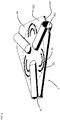
- FIG. 1 A first embodiment in accordance with the invention is shown in Figure 1 .
- a modular skeleton structure having a hexagonal pattern is shown in an erected state.
- the modular skeleton structure 1 comprises a number of elongate members 2; a number of connection units 3 comprising three entrances 31 for connecting three elongate members at mutual angles of 120° in a plane, in a relaxed un-tensioned state, wherein the elongate members 2 or the connection units 3 or both are made from a flexible material wherein the elongate members 2 are connected with the connection units 3 in a hexagonal pattern 100 to a rectangular plane 10 comprising two sides 11, 12 and two bendable sides 13, 14, which rectangular plane is bent into in a semi-cylindrical shaped skeleton structure 1 comprising two long sides 11, 12 in a bottom plane 15 and two bended sides 13, 14.
- semi-cylindrical shaped implies that the plane 10 is bend to a semi-elliptical or approximately half circular shape.
- An elliptical or circular shape is preferred because the bending stress is more equally spread over the connection units 3 and elongate members 2 and the height of the structure 1 and area of the enclosed bottom plane can both be optimised, but the shape does not necessarily have to be circular or elliptical.
- Other curved shapes are also possible like elliptical or parabolical of a slightly flattened circular shape, for example the part of plane 10 adjacent to the bottom plane may be kept more vertical and then bend inward more sharply.
- the hexagonal patterned rectangular planar skeleton structure is thus bent to enclose a space with a substantially semi-cylindrically curved plane, a bottom plane and side planes.
- the space can define areas for growing plants, sheltering, supporting growing plants, camouflage, protecting coral or any other use.
- the elongate members 2 are made from composite material, metal, wood, bamboo or alternative organic stems or any combination thereof. This allows the material to be sourced in an easy manner, while still providing enough structural strength, especially when considering the density of the used material and the volume the material may have as a result of the required strength.
- the choice of material typically is a compromise in strength, durability and low costs.
- Combinations comprise intra- and inter-member combinations. So, one member can be combination of materials, but the number of members may also comprise a set of members of one material and one or sets of members made of a different material. Having a combination of materials provides the possibility to introduce different flexibility and strengths on different parts of the modular skeleton structure.
- the rectangular plane 10 in the skeleton structure comprises two or more areal parts with different elongate members.
- the elongate members near edges 11 and/or 12 may be stiffer or less stiff than in the middle, such that the roof structure is flattened and/or the skeleton structure near the edge are more perpendicular than in a cylindrical shape.
- the length of elongate members 2 depends on one hand mainly on the ease of use in building the modular structure and in ease of handling of the kit of parts on the other hand the requirements of the skeleton structure in terms of size, volume, weight and strength. For larger skeleton structures, a higher length of the elongate members 2 may be chosen, but in view of the required stiffness then also the diameter or wall thickness of the elongated members must be increased.
- the elongate members 2 may have any cross-sectional shape.
- the cross-section, perpendicular to the length axis of the elongate member 2 may be circular, square, rectangular, or ellipsoidal shaped.
- the cross-section, perpendicular to the length-axis of the elongate member 2 is circular, more preferably hollow cylindrical.
- the elongate members 2 have a cross-sectional surface area of less than about 2000 mm 2 , preferably less than about 500 mm 2 , more preferably less than about 200 mm 2 , even more preferably less than about 100 mm 2 and wherein the length of the elongate member 2 preferably is between 5 cm and 500 cm, more preferably between 30 cm and 300 cm.
- the length of the elongated member is between 2 and 1000, more preferably between 5 and 100, even more preferably between 10 and 100 times shorter than the length of the two bendable sides 13, 14.
- the elongate members 2 are preferably straight and preferably cylindrical but may also be formed in any other appropriate shape.
- the elongate members 2 may for example also have a sinusoidal shape disposed therein.
- the skeleton structure 1 can be erected by tensioning the hexagonally patterned rectangular plane 10. Therefore, at least some of the components of the hexagonally patterned rectangular plane 10 must be adapted to deform under applied tension. Preferably this deformation is elastic. This can be achieved by allowing the elongate members 2 to deform under tension and/or the connection units 3 to deform under tension.
- the elongate members 2 are made from a flexible material, preferably having an Elasticity modulus of between about 0.01 and 200 GPa as defined and determined in ASTM E111, preferably of between about 0.1 and 100 GPa, more preferably of between about 0.5 and 50 GPa, even more preferably of between 1 and 30 GPa and bend under the torque applied when erecting the rectangular plane by bringing the bendable sides 13, 14 closer together.
- the Elasticity modulus of the elongate members 2 at least partly determines the resistance for bringing the bendable sides 13, 14 together.
- connection unit 3 is made from a strong and durable material which holds the elongate members 2 disposed in the entrances 31. It is preferably made of a stiff material that does not substantially deform under a tensioning moment from the elongate members when bending the hexagonal patterned rectangular plane 10.
- the elongate members 2 deform elastically when the plane 10 is erected and adopts a substantially semi-cylindrical shape. Strong and durable in this embodiment entails that there is no need for the connection unit 3 to deform under tension.
- the connection unit can be made from strong material such as e.g. aluminium, steel, composite, polymer, etc. Deformation in this context entails elastic deformation. While plastic deformation may occur in certain instances, the deformation should generally be reversible when the tension is removed from the components of the structure 1.
- connection unit 3 is formed from a strong and durable material, the curved shape of the plane is then predominantly the result of the flexion in the elongate members 2. In this embodiment, flexion of the connection unit 3 is minimised with respect to the elongate members 2. Having a connection unit 3 that does not allow for substantive deformation aids in the simplicity and durability of the connection unit. Since the connection unit 3 is substantially flat, the hexagonal structure 10 can be created while resting on the ground. Once the sides 11 and 12 are brought closer together, the elongate members 2 may deform, but the connection unit 3 has no substantial deformation with respect to the elongate members 2. As a result, the connection units 3 can be made from a strong and durable material, thereby minimizing wear and increasing life span.
- connection unit 3 is made from metal, wood or an elastic material such as a polymer and/or comprising shape features designed to enable the connection unit to accommodate torque for deformation on bending.
- the openings are tight fit to the members so as to not allow any dispositioning on bending and the material of the connection units is preferably substantially stiff and strong in combination with elongate members that are bendable.
- connection unit 3 is made from a flexible material which bends when elongate members 2 disposed in the entrances 31 create a tensioning moment on the connection unit 3. The connection unit 3 may then deform under a load applied to the connection unit 3 by the elongate members 2 as a result of the formation of the shape of the modular skeleton structure 1.
- the elongate members 2 may be substantially rigid or flexible.
- the connection unit 3 can be made from elastomers, rubber or elastic material and/or comprising shape features designed to enable the connector itself to accommodate deformation on bending.
- connection units 3 may comprise one or more, preferably three, attachment units 32. These attachment units can be used to connect certain appliances to the modular skeleton structure 1. For example, shadow cloth, dew chords or strengthening wires may be attached to the attachment units 32.
- the attachment units 32 may be tabs 33 formed in the surface 30 of the connection unit 3. Having tabs 33 that are formed in the surface 30 of the connection unit 3 aids in an increased simplicity in the production process of the connection units 3.
- the connection units 3 may be created from metal parts or injection moulded or press moulded parts.
- the tabs 33 may be integrally formed in production or formed by combining two sides. Alternatively, holes are drilled as post-treatment in the surface 30. In another embodiment, tabs 33 can be hooks on a surface 30 of the connection unit 3.
- the one or more attachment units 32 may be flexible tabs 33, adapted to bend in an outwardly direction relative to the substantially flat surface 30. Having flexible tabs 33 minimizes the complexity of the production process and more particularly aids in efficient packaging of the parts of the modular skeleton structure 1 when packaged for shipping. Especially not having multiple protruding elements from the connection unit 3 is advantageous for packaging.
- connection unit 3 may be formed from two sides 301, 302, each having three indentations 331 to form the entrances 31 when coupled.
- the production process of the connection unit 3 is simplified resulting in lower production times and costs when compared to forming the connection unit 3 from an integral block of material or by forming the connection unit 3 from separate components.
- imperfections e.g., welding seams, bolts, rivets
- the resulting connection unit 3 thus provides less wear on any foils or covers applied thereover.
- connection unit 3 may be formed from three short pipes that are clamped, glued or moulded together.
- the pipes may be held by a central clamp on the intersection of the pipes to add strength to the connection unit 3.
- the central clamp may be rigid and preferably the central clamp is strengthened and contains a metal or plastic hook as an attachment unit 32.
- the hook may be screwed in during the construction or it may be formed as an integrated part of the plastic construction by injection mounding technique.
- the two sides 301, 302 may be identical to reduce production cost.
- the sides 301, 302 can be attached by any attachment means, preferably by welding, gluing or soldering.
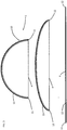
- Figure 3 shows a sectional view of one embodiment of the invention showing the modular skeleton structure showing three phases during its erection.
- the modular structure 1 further comprises a tensioning device 4 for applying tension to at least one of the sides 11, 12 of the plane 10, for erecting the structure 1 and/or for keeping the structure erect.
- a tensioning device 4 may be attached to at least one of the sides 11, 12 for applying a tension that is equal to the resulting outward force due to the torque applied to the elongate members 2 and/or the connection units 3.
- the tensioning device 4 can keep the structure 1 upright (e.g.
- the tensioning device is preferably selected from the group of ropes, chains, tensioning bands, pulleys, spanner wrenches, a tension strap with a ratchet, a rattle strap or any other appropriate tensioning device.
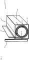
- Figure 4 shows a side view of one embodiment of the invention showing a horizontal support beam 5.
- the modular structure 1 further comprises a support beam 5 along at least part of side 11 or side 12 or both sides 11 and 12 of the surface 10 which supporting beam has connection means 51 connecting to the connection units 3 or to the elongate members 2 of the semi-cylindrical skeleton structure.
- the support beam 5 allows for connection the sides 11 and/or 12, thereby providing for a uniform distribution of the forces applied by the plane 10 to the surface onto which the structure 1 is placed.
- the support beam 5 is modular, comprising connectable support beam elements.
- the connectable support beam elements are provided with connection means or are connectable with separate support beam element connectors. Having a modular support beam allows for the application of a support beam over an increased length of at least one of the sides 11, 12, while still allowing the parts of the structure 1 to remain within a maximum dimension to fit in a kit of parts.
- the support beam elements are connected by the support beam element connectors.
- the support beam element connectors may be clips, tube connectors, straps, bolts, rivets, or any other appropriate connection means.
- the support beam element connectors are able to connect the support beam elements without substantial intermittent change of the support beam properties.
- connection means 51 in the support beam 5 may be a series of receiving openings, preferably cavities, for receiving an elongate member 2 therein, preferably a cavity with a length axis perpendicular to the long beam axis in case the hexagons in the surface are oriented with elongate members perpendicular on side 11 and/or 12 of the surface area.
- This substantially perpendicular connection may be advantageous as it maximizes the tensional torque around the centre-line of the plane between sides 11 and 12, thereby increasing the efficiency of the applied force to the sides 11 and 12 when erecting the structure 1.
- connection means 51 in the support beam 5 may be a series of pins for engaging with a hollow member.
- the hollow member may be an elongate member 2 or a connection unit 3, that engages with the connection means 51 to secure a side 11, 12 of the plane 10 to the support beam 5.
- connection means 51 secure a side 11, 12 of the plane 10 to the support beam 5 in another fashion, such as bolting a connection unit 3 to the support beam 5.
- connection means 51 may be a set of hooks or rounded grips that engage with the straight series of elongate members 2.
- the connection units 3 may also be connected to the support beam 5 by the connection means 51 in this embodiment.
- the support beam 5 may comprise a tension attachment element 52 adapted to be coupled to the tensioning device 4.
- the tension attachment element 52 may for instance be a hook-like element disposed on the side of the body 50 of the support beam 5 that may connect to a tensioning device 4 such as ropes, chains, tensioning bands, pulleys, spanner wrenches, a tension strap with a ratchet, a rattle strap or any other appropriate tensioning device.
- the support beam 5 may comprises means to contain and dispatch a sheet 6, preferably a foil, net or shadow cloth for covering the plane 10 of the semi-cylindrical structure 1. Applying a foil or a shadow cloth to cover the plane 10 can allow to control the climate in the structure 1. Applying a net to cover the plane 10 may allow to create a protected area in the structure 1.
- Figure 5 shows a cross-sectional view of one embodiment of the invention showing a clamping mechanism.
- the support beam 5 comprises a body 50 and a clamping mechanism 7 attached thereto, wherein a sheet 6, preferably a foil or shadow cloth is coupled with the clamping mechanism 7 of the one or more horizontal support beams 5.
- a clamping mechanism 7 attached to the one or more horizontal support beams 5 allows for an increased simplicity and a reduction in parts and volume of parts, thereby achieving advantageous results for the packaging and transportation of the product.
- the clamping mechanism 7 may comprise a first cylindrical element 71 around which the sheet 6, preferably a foil, net or shadow cloth is wrapped, and a second cylindrical element 72 disposed around the first cylindrical element 71 and the sheet 6, wherein the first cylindrical element 71 is rotationally movable with respect to the body 50 of the horizontal support beam 5, wherein the second cylindrical element 72 comprises an opening through which the sheet 6 traverses.
- the sheet rolls around the first cylindrical element 71 thereby being frictionally bound to the outer surface of the first cylindrical element 71.
- the free rotation of the first cylindrical element 71 can be limited, thereby clamping the sheet between the inner surface of the second cylindrical element 72 and the outer surface of the first cylindrical element 71.
- connection of the sheet to the horizontal support beam 5 may be achieved by connecting the sheet directly to the body 50 of the support beam 5.
- the sheet is not connected to the support beam 5 but rather is attached to the soil onto which the structure 1 is placed by, for example, pins that are driven into the ground, through the sheet.
- the first cylindrical element 71 of the clamping mechanism 7 of a first horizontal support beam 5 may be coupled to the first cylindrical element 71 of the clamping mechanism 7 of a second horizontal support beam 5 with a pipe-connector. This allows for the erection of a long structure without the need for an uninterrupted cylindrical element along the entire length of the structure to be erected.
- the clamping mechanism 7 may further comprise a housing 73, wherein the first and second cylindrical elements 71, 72 are disposed in the housing 73, wherein the housing 73 comprises a slit opening through which the foil 6 traverses. Closing the housing 73 may block the rotation of the first and/or second cylindrical elements 71, 72, thereby clamping the foil.
- the housing 73 may be an integral part of the body 50 of the support beam 5. Multiple housing elements 73 may be provided in the kit of parts to allow for the formation of a longitudinally formed housing 73 that is longer than the maximum dimension of the kit of parts.
- the erected semi-cylindrical skeleton structure is provided with an internal secondary skeleton attached to the attachment units 32 of the connection units 3, wherein the internal secondary skeleton comprises tensioning members attached between at least two of the attachment units 32, preferably attached between at least two, more preferably at least 3, of the attachment units 32 in hexagons in at least part of the surface of the hexagonal patterned skeleton 10, wherein the tensioning members are preferably selected from the group of ropes, strings, elastic bands, tie raps, metal screw tensioning members or combinations thereof.
- Applying an internal secondary skeleton to the inside of the structure 1 may lead to a higher structural integrity of the total structure 1.
- the internal secondary skeleton can also be used to influence the shape.
- the modular structure 1 may further comprise additional components attached to the at least one attachment units 32, such as shade cloth or dripping rope.
- the modular structure 1 may further comprise a sheet 6, preferably a foil, a net or a shadow cloth, applied over the outer plane of the modular structure 1.
- the modular structure 1 may further comprise ground fixation pins attached thereto, preferably attached to the support beams 5.
- the modular structure 1 is a greenhouse, a shelter, a house, encapsulation, shielding container, a camouflage device, but preferably a greenhouse, shadow house or coral encapsulation.
- the sheet 6 is a UV greenhouse film.
- the sheet may be a shadow cloth.
- the sheet is a protection net allowing fish to pass.
- Figure 6 shows a plan view of one embodiment of the invention showing the modular skeleton having a side that is closed off by closing means 8.
- the sides of the semi-cylindrical skeleton structure defined by the bendable sides 13 or 14 and the bottom plane 15 of the semi-cylindrical shape are also provided with closing means 8, preferably by panel or cloth or sheet.
- the closing means 8 may comprise textile, net and/or foil material.
- the closing means 8 further comprises a door-opening 81, wherein the door-opening 81 can preferably be closed in a substantially airtight fashion. Having a door-opening that can be opened and closed allows for the user to influence the inside climate in an advantageous manner. For example, in a desert environment, opening the door-opening 81 during the night can allow moisture to be captured inside the structure 1. Closing the door-opening 81 during the day can then trap the moisture inside the structure 1, thereby increasing the moisture delivered to the plants in the structure 1.
- kits of parts for building the modular structure 1 comprising: a number of elongate members 2; a number of connection units 3 for connecting the elongate members 2; optionally one or more support beams 5, preferably comprising support beam elements and support beam connectors, optionally one or more tensioning devices 4 for applying tension to erect a hexagonal assembly of elongate members 2 and connection units 3, wherein preferably none of the components of the modular structure kit exceed a length of 500 cm, preferably 125 cm, more preferably 50 cm.
- Another aspect of the invention comprises a method for erecting the modular skeleton structure 1 comprising; providing a kit of parts for building the modular skeleton structure 1; coupling a plurality of the elongate members 2 with a plurality of the connection units 3 in a hexagonal pattern to form a rectangular plane 10 having two sides 11, 12 and two bendable sides 13, 14; and moving the two sides 11, 12 of the plane 10 towards each other and bending and raising the plane 10 to form a semi-cylindrical shaped skeleton structure 1.
- the method for erecting the modular skeleton structure 1 may further comprise using a tensioning device 4 for moving the two sides 11, 12 of the plane 10 towards each other by coupling the tensioning device 4 with at least one of the two sides 11, 12 of the plane 10; and engaging the tensioning device 4 to apply tension to at least one of the two sides 11, 12 of the plane 10 to raise the plane 10 to form a substantially semi-cylindrical shape.
- the method for erecting the modular skeleton structure 1 may further comprise the step of applying a sheet 6, preferably a foil, net or shadow cloth over the erect modular structure 1 and optionally also a step of providing closing means 8 to close the side planes of the semi-cylindrical skeleton structure.
- the method for erecting the modular skeleton structure 1 may further comprise the step of increasing the mass of the support beams or of clamping mechanism 7 by filling the first cylindrical element 71 with a material having a density of at least 100 kg/m 3 .
- Increasing the weight of the support beam 5, preferably the clamping mechanism 7 by applying a material having a relatively high density to it, such as rocks or sand, can increase the stability of the structure in harsh conditions, while limiting the need to increase the weight of the components of the structure 1.
- connection unit 3 for connecting elongate members 2 in a plane of a modular structure 1, the connection unit 3 comprising: a substantially flat surface 30; three entrances 31 adapted to receive elongate members 2 therein; and one or more attachment units 32, wherein the entrances 31 are provided in the substantially flat surface 30, in a relaxed un-tensioned state, having angles of about 120° between them to engage elongate members 2 in a substantially flat plane.
- An embodiment of this aspect of the invention can be seen in Figure 2 of the drawings.
- connection unit 3 may be adapted to flex when elongate members 2 disposed in the entrances 31 create a tensioning moment on the surface 30 of the connection unit 3.
- the one or more attachment units 32 may be tabs 33 formed in the substantially flat surface 30.
- the one or more attachment units 32 may be flexible tabs 33, adapted to bend outwardly, relative to the substantially flat surface 30.
- connection unit 3 may be formed from two sides 301, 302, each having three indentations 331 to form the entrances 31 when coupled.
- Figure 7 shows another aspect of the invention relating to an edge connection unit for connecting elongate members at the edges 13 and/or 14, which edge connection unit comprise three entrances adapted to receive elongate members wherein the entrances are provided in a substantially flat surface in a relaxed un-tensioned state, wherein 2 entrances are at an angles of about 180° and the third entrance is at 60° and 120° of the first and second entrance.
- These connection units can be used in combination with (coupled) edge elongate members having twice the length of the elongate members in the hexagons to form a straight edge 13 and 14, which contributes to the strength of the skeleton structure and makes it easier to connect closing means 8 at the side planes.
- the kit of parts further comprises such edge connection members and edge elongate members.
- the modular skeleton structure 1 is a support structure in a greenhouse, tent, encapsulation, shielding container or shelter.
- the modular skeleton structure 1 has many uses, it may for example serve as a solution for areas where shelter is needed quickly (e.g. military applications).
- the modular skeleton structure 1 may also serve as a greenhouse, which can easily be erected.
- the invention also relates to a greenhouse, tent, encapsulation, shielding container or shelter comprising the modular skeleton structure of the invention as a support structure.
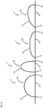
- Figure 8 shows different semi-cylindrical shapes of the cross-section of the modular skeleton structure.
- the semi-cylindrical shape may be perfectly semi-cylindrical but may also be ellipsoidal, skewed or substantially straight in some areas, if so desired.
- the cross-sectional shape and the size of the modular skeleton structure 1 may be varied as desired by the user. Because of the modular characteristics and the possibility of components of the structure to deform under tension, the modular skeleton structure 1 of the present disclosure is highly versatile.
Landscapes
- Life Sciences & Earth Sciences (AREA)
- Environmental Sciences (AREA)
- Health & Medical Sciences (AREA)
- General Health & Medical Sciences (AREA)
- Toxicology (AREA)
- Tents Or Canopies (AREA)
Priority Applications (1)
| Application Number | Priority Date | Filing Date | Title |
|---|---|---|---|
| EP19187437.9A EP3766337A1 (fr) | 2019-07-19 | 2019-07-19 | Systèmesquelette modulaire |
Applications Claiming Priority (1)
| Application Number | Priority Date | Filing Date | Title |
|---|---|---|---|
| EP19187437.9A EP3766337A1 (fr) | 2019-07-19 | 2019-07-19 | Systèmesquelette modulaire |
Publications (1)
| Publication Number | Publication Date |
|---|---|
| EP3766337A1 true EP3766337A1 (fr) | 2021-01-20 |
Family
ID=67438307
Family Applications (1)
| Application Number | Title | Priority Date | Filing Date |
|---|---|---|---|
| EP19187437.9A Withdrawn EP3766337A1 (fr) | 2019-07-19 | 2019-07-19 | Systèmesquelette modulaire |
Country Status (1)
| Country | Link |
|---|---|
| EP (1) | EP3766337A1 (fr) |
Citations (9)
| Publication number | Priority date | Publication date | Assignee | Title |
|---|---|---|---|---|
| FR2324222A1 (fr) | 1974-05-07 | 1977-04-15 | Charbonnages Ste Chimique | Abri tunnel |
| US4589236A (en) * | 1984-06-05 | 1986-05-20 | Mcallister Jack G | Geometric frame assembly |
| US4603519A (en) * | 1984-12-17 | 1986-08-05 | Lew Hyok S | Geodesically reinforced honeycomb structures |
| ES1017970U (es) | 1991-07-03 | 1992-01-01 | Gatti Canotti Umberto | Invernadero modular. |
| JP2003176600A (ja) * | 2001-12-07 | 2003-06-24 | Dairyu Seiki Kk | 立体フレーム |
| US20060291952A1 (en) * | 2005-06-23 | 2006-12-28 | Wood O G | Structural member connector |
| KR20110005497A (ko) * | 2009-07-10 | 2011-01-18 | 심종석 | 다축 연결 조인트 및 이를 이용한 아치형 하우스 구조물 |
| KR20110009528A (ko) * | 2009-07-22 | 2011-01-28 | 심종석 | 다축 연결 조인트 및 이를 이용한 아치형 하우스 구조물 |
| CN203626286U (zh) * | 2013-12-06 | 2014-06-04 | 金华市广明生态农业综合开发有限公司 | 拱棚建筑保温隔热结构 |
-
2019
- 2019-07-19 EP EP19187437.9A patent/EP3766337A1/fr not_active Withdrawn
Patent Citations (9)
| Publication number | Priority date | Publication date | Assignee | Title |
|---|---|---|---|---|
| FR2324222A1 (fr) | 1974-05-07 | 1977-04-15 | Charbonnages Ste Chimique | Abri tunnel |
| US4589236A (en) * | 1984-06-05 | 1986-05-20 | Mcallister Jack G | Geometric frame assembly |
| US4603519A (en) * | 1984-12-17 | 1986-08-05 | Lew Hyok S | Geodesically reinforced honeycomb structures |
| ES1017970U (es) | 1991-07-03 | 1992-01-01 | Gatti Canotti Umberto | Invernadero modular. |
| JP2003176600A (ja) * | 2001-12-07 | 2003-06-24 | Dairyu Seiki Kk | 立体フレーム |
| US20060291952A1 (en) * | 2005-06-23 | 2006-12-28 | Wood O G | Structural member connector |
| KR20110005497A (ko) * | 2009-07-10 | 2011-01-18 | 심종석 | 다축 연결 조인트 및 이를 이용한 아치형 하우스 구조물 |
| KR20110009528A (ko) * | 2009-07-22 | 2011-01-28 | 심종석 | 다축 연결 조인트 및 이를 이용한 아치형 하우스 구조물 |
| CN203626286U (zh) * | 2013-12-06 | 2014-06-04 | 金华市广明生态农业综合开发有限公司 | 拱棚建筑保温隔热结构 |
Similar Documents
| Publication | Publication Date | Title |
|---|---|---|
| CN107027335B (zh) | 便携式光伏组件阵列 | |
| DK2773819T3 (en) | Construction unit for immediate or permanent shelter | |
| US20030089390A1 (en) | Steel pole for a rectangular dome-shaped tent | |
| US7434359B2 (en) | Constructing geodesic domes with panels | |
| CN108400750B (zh) | 一种斜拉式柔性光伏支架单元及光伏支架 | |
| WO2003002830A3 (fr) | Structures auto-haubanees | |
| JPH0647839B2 (ja) | 構造物の建設方法 | |
| US6996942B2 (en) | Constructing geodesic domes | |
| US20090071080A1 (en) | Temporary construction and associated method of assembly | |
| US6434891B1 (en) | Reinforced panel arch for soft-covered buildings and the like | |
| RU2000102899A (ru) | Крепежный хомут между проходящей через крышу строительной конструкцией и подвесным потолком | |
| US6615552B2 (en) | Segmented articulated pole structure | |
| US20060033335A1 (en) | Node element for pneumatic components | |
| EP3766337A1 (fr) | Systèmesquelette modulaire | |
| US5899028A (en) | Saddle span shelter and joining system | |
| JP3544862B2 (ja) | 形状可変トラス架構およびこの形状可変トラス架構を用いた形状可変立体トラス架構並びにこの形状可変立体トラス架構を用いた形状可変天井および開閉式屋根 | |
| US20030024564A1 (en) | Light-weight flexible shelter structure with improved volume | |
| SK130795A3 (en) | Emergency shelter | |
| US20130055654A1 (en) | Modular house building system | |
| US5214893A (en) | Compression framing system | |
| US4432381A (en) | Windbreaker | |
| US4436284A (en) | Tensed wire suspension system | |
| EP0093280B1 (fr) | Elément de construction composé d'éléments de support et éléments de surface adjacents en matière plastique | |
| WO1984000467A1 (fr) | Enceintes portatives ou legeres | |
| KR100575429B1 (ko) | 골조고정구 |
Legal Events
| Date | Code | Title | Description |
|---|---|---|---|
| PUAI | Public reference made under article 153(3) epc to a published international application that has entered the european phase |
Free format text: ORIGINAL CODE: 0009012 |
|
| STAA | Information on the status of an ep patent application or granted ep patent |
Free format text: STATUS: THE APPLICATION HAS BEEN PUBLISHED |
|
| AK | Designated contracting states |
Kind code of ref document: A1 Designated state(s): AL AT BE BG CH CY CZ DE DK EE ES FI FR GB GR HR HU IE IS IT LI LT LU LV MC MK MT NL NO PL PT RO RS SE SI SK SM TR |
|
| AX | Request for extension of the european patent |
Extension state: BA ME |
|
| STAA | Information on the status of an ep patent application or granted ep patent |
Free format text: STATUS: THE APPLICATION IS DEEMED TO BE WITHDRAWN |
|
| 18D | Application deemed to be withdrawn |
Effective date: 20210721 |