EP3766438B1 - Einstellbarer bohrführer - Google Patents
Einstellbarer bohrführer Download PDFInfo
- Publication number
- EP3766438B1 EP3766438B1 EP20186416.2A EP20186416A EP3766438B1 EP 3766438 B1 EP3766438 B1 EP 3766438B1 EP 20186416 A EP20186416 A EP 20186416A EP 3766438 B1 EP3766438 B1 EP 3766438B1
- Authority
- EP
- European Patent Office
- Prior art keywords
- sleeve
- aimer arm
- assembly
- distance
- drill
- Prior art date
- Legal status (The legal status is an assumption and is not a legal conclusion. Google has not performed a legal analysis and makes no representation as to the accuracy of the status listed.)
- Active
Links
Images



Classifications
-
- A—HUMAN NECESSITIES
- A61—MEDICAL OR VETERINARY SCIENCE; HYGIENE
- A61B—DIAGNOSIS; SURGERY; IDENTIFICATION
- A61B17/00—Surgical instruments, devices or methods
- A61B17/16—Instruments for performing osteoclasis; Drills or chisels for bones; Trepans
- A61B17/17—Guides or aligning means for drills, mills, pins or wires
-
- A—HUMAN NECESSITIES
- A61—MEDICAL OR VETERINARY SCIENCE; HYGIENE
- A61B—DIAGNOSIS; SURGERY; IDENTIFICATION
- A61B17/00—Surgical instruments, devices or methods
- A61B17/16—Instruments for performing osteoclasis; Drills or chisels for bones; Trepans
- A61B17/1613—Component parts
- A61B17/1626—Control means; Display units
-
- A—HUMAN NECESSITIES
- A61—MEDICAL OR VETERINARY SCIENCE; HYGIENE
- A61B—DIAGNOSIS; SURGERY; IDENTIFICATION
- A61B17/00—Surgical instruments, devices or methods
- A61B17/16—Instruments for performing osteoclasis; Drills or chisels for bones; Trepans
- A61B17/17—Guides or aligning means for drills, mills, pins or wires
- A61B17/1739—Guides or aligning means for drills, mills, pins or wires specially adapted for particular parts of the body
- A61B17/1778—Guides or aligning means for drills, mills, pins or wires specially adapted for particular parts of the body for the shoulder
-
- A—HUMAN NECESSITIES
- A61—MEDICAL OR VETERINARY SCIENCE; HYGIENE
- A61B—DIAGNOSIS; SURGERY; IDENTIFICATION
- A61B17/00—Surgical instruments, devices or methods
- A61B17/16—Instruments for performing osteoclasis; Drills or chisels for bones; Trepans
- A61B17/17—Guides or aligning means for drills, mills, pins or wires
- A61B17/1796—Guides or aligning means for drills, mills, pins or wires for holes for sutures or flexible wires
-
- A—HUMAN NECESSITIES
- A61—MEDICAL OR VETERINARY SCIENCE; HYGIENE
- A61B—DIAGNOSIS; SURGERY; IDENTIFICATION
- A61B17/00—Surgical instruments, devices or methods
- A61B2017/00367—Details of actuation of instruments, e.g. relations between pushing buttons, or the like, and activation of the tool, working tip, or the like
- A61B2017/00389—Button or wheel for performing multiple functions, e.g. rotation of shaft and end effector
-
- A—HUMAN NECESSITIES
- A61—MEDICAL OR VETERINARY SCIENCE; HYGIENE
- A61B—DIAGNOSIS; SURGERY; IDENTIFICATION
- A61B17/00—Surgical instruments, devices or methods
- A61B2017/00367—Details of actuation of instruments, e.g. relations between pushing buttons, or the like, and activation of the tool, working tip, or the like
- A61B2017/00398—Details of actuation of instruments, e.g. relations between pushing buttons, or the like, and activation of the tool, working tip, or the like using powered actuators, e.g. stepper motors, solenoids
-
- A—HUMAN NECESSITIES
- A61—MEDICAL OR VETERINARY SCIENCE; HYGIENE
- A61B—DIAGNOSIS; SURGERY; IDENTIFICATION
- A61B17/00—Surgical instruments, devices or methods
- A61B2017/00367—Details of actuation of instruments, e.g. relations between pushing buttons, or the like, and activation of the tool, working tip, or the like
- A61B2017/00407—Ratchet means
Definitions
- the present disclosure relates generally to surgical drill guides. More specifically, the present disclosure relates to adjustable drill guide assemblies for the positioning and orienting of bone tunnels to be drilled in a glenoid bone.
- a Latarjet operation also known as the Latarjet-Bristow procedure, is a surgical procedure used to treat recurrent shoulder dislocations, typically caused by bone loss or a fracture of the glenoid.
- the Latarj et procedure typically involves the removal and transfer of a section of the coracoid process, as well as its attached soft tissue, to the glenoid cavity. This placement of the coracoid acts as a bone block which, combined with the transferred soft tissue, prevents further dislocation of the joint.
- holes are generally drilled through both of the coracoid and the glenoid through which screws or sutures attached to anchors or buttons can be placed for securing the section of the coracoid to the glenoid.
- Surgical drill guides can be used to place the holes in the glenoid neck at a fixed distance from the glenoid articulating surface to align with the drill holes of the coracoid.
- misalignment between the two sets of holes can occur.
- the suture/anchor or button constructs generally allow some tolerance in aligning the coracoid flush to the glenoid surface, because the suture has play within the drill holes.
- retroactive alignment is not possible once the holes are drilled.
- Surgeons generally address the misalignment by shaving down the thickness of the coracoid with a burr.
- use of a burr can potentially cause cartilage damage and affect the accuracy of the surface alignment between the glenoid and the coracoid, as well as affecting surface quality.
- CN106618720A relates to a vertical adjustable fixed point malposition distance guide needle collimation hollow screw fixation minimally invasive device.
- a drill guide assembly in which the drill guide is adjustable for properly aligning the holes in the glenoid with the holes in the coracoid in a Latarjet procedure.
- the drill guide has an aimer arm extending from the body of the drill guide which has a fixed angle with respect to a drill sleeve inserted through the guide.
- the aimer arm can move up or down relative to the drill sleeve while maintaining the fixed angle relative to the drill sleeve by actuation of a translation member on the body.
- the aimer arm can move in a stepped fashion in 1 mm increments, or in a non-stepped fashion.
- a locking knob on the aimer arm can be used to lock the aimer arm at the desired position.
- the component parts of the drill guide assembly can be disassembled for cleaning.
- Examples of the drill guide assembly of this disclosure may include one or more of the following, in any suitable combination.
- a drill guide assembly of this disclosure includes an elongate body including a proximal end, a distal end and a longitudinal axis extending between the proximal and distal ends. At least one channel extends along the longitudinal axis of the body from the proximal end to the distal end. A sleeve is slidably disposed within the at least one channel. A distal end of the sleeve is configured to be secured to a first surface of a bone.
- An aimer arm extends distally from the body. A distal end of the aimer arm is configured to be secured to a second surface of the bone. The aimer arm extends at a fixed angle with respect to the sleeve. A vertical distance between the aimer arm and the sleeve is adjustable to a pre-selected distance by actuation of a translation member on the body such that the aimer arm maintains the fixed angle with respect to the sleeve.
- the assembly further includes a handle extending from a lower surface of the body configured to be held by a user.
- the preselected distance is between 6 mm and 9 mm.
- the at least one channel is two channels extending on opposing sides of the aimer arm, and a distance between the two channels is about 10 mm.
- the sleeve includes a bore extending from a proximal end to a distal end of the sleeve for the passage of a drill.
- the assembly further includes a locking mechanism for locking the sleeve at a predetermined position within the at least one channel.
- the proximal end of the sleeve includes a depth stop.
- a diameter of the depth stop selected to be larger than a diameter of the channel for limiting distal movement of the sleeve within the channel.
- the fixed angle is 10°.
- the distance between the aimer arm and the sleeve is adjustable in a stepped or a non-stepped manner.
- the assembly further includes an alignment member extending from an upper surface of the body adjacent the distal end of the body.
- the alignment member defines a plurality of longitudinal slots.
- the translation member is a rotatable wheel.
- the aimer arm extends through opposing ones of the plurality of slots along the longitudinal axis.
- a projection of the aimer arm is configured to serially engage the rotatable wheel such that the distance between the aimer arm and the sleeve is adjustable by rotation of the rotatable wheel by 90°.
- a pivot point of the rotatable wheel is offset from a center of the rotatable wheel in both a horizontal and a vertical direction.
- a proximal end of the aimer arm includes a locking knob for securing the aimer arm against the alignment member at the preselected distance.
- the assembly further includes a compression spring disposed within the alignment member for biasing the projection of the aimer arm against the rotatable wheel.
- the terms “about” and “substantially” are used to represent the inherent degree of uncertainty that may be attributed to any quantitative comparison, value, measurement, or other representation.
- the terms “about” and “substantially” are also used herein to represent the degree by which a quantitative representation may vary from a stated reference without resulting in a change in the basic function of the subject matter at issue.
- “Comprise,” “include,” and/or plural forms of each are open ended and include the listed parts and can include additional parts that are not listed.
- “And/or” is open-ended and includes one or more of the listed parts and combinations of the listed parts. Use of the terms “upper,” “lower,” and the like is intended only to help in the clear description of the present disclosure and are not intended to limit the structure, positioning and/or operation of the disclosure in any manner.
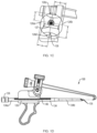
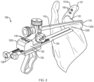
- the assembly 100 includes a guide body 102 having a proximal end 102a and a distal end 102b.
- An upper surface 102c and a lower surface 102d extend between the proximal end 102a and the distal end 102b of the body 102.
- a handle 104 extends from the lower surface 102d of the body 102 and is configured to be held by a user in a "pistol-style" configuration.
- the handle 104 is an in-line handle, formed substantially coaxially with the body 102.
- the body 102 further includes at least one cylindrical channel 120 extending from the proximal end 102a to the distal end 102b of the body 102 for slidably receiving an elongate drill sleeve 134 ( FIG. 1D ).
- the drill sleeve 134 is configured for the passage of a guidewire (not shown) for locating the bone tunnels to be drilled in the bone.
- two channels 120 are defined on opposite sides of the body 102 configured for positioning two parallel bone tunnels through the bone.
- a distance between the channels 120 is about 10 mm, ensuring accurate and consistent placement of the bone tunnels about 10 mm apart within the bone.
- An elongate aimer arm 110 extends distally from the body 102 at about a 10° angle toward the longitudinal axis L of a path defined by the channels 120 for insertion of the drill sleeve 134.
- the aimer arm 110 includes a distal tip 116 with a spiked hook 118 which is configured to contact a bone surface.
- the distal tip 116 could be pointed or comprise a blunted end, such as a spherical tip.
- the assembly 100 is configured such that a vertical distance between the aimer arm 110 and the drill sleeve 134 is adjustable based on a pre-measured thickness of the bone to be drilled by actuation of a translation member on the body, such as a rotatable wheel 126, while still maintaining the 10° angle between the aimer arm 110 and the drill sleeve 134.
- the upper surface 102c of the body 102 also includes at least one threaded opening 128 adjacent the proximal end 102a for receiving a threaded ratchet pawl (not shown) for locking the drill sleeve 134 within the channel 120 at a desired position.
- an alignment member 106 extends from the upper surface 102c of the body 102 adjacent the distal end 102b.
- the alignment member 106 defines a plurality of longitudinal slots 108 within the alignment member 106.
- the aimer arm 110 extends through opposing slots 108 along the longitudinal axis and is vertically moveable within the slots 108 relative to the drill sleeve 134.
- a proximal end of the aimer arm 110 includes a locking knob 114 which can be used to secure the aimer arm 110 in the desired vertical position within the slots 108.
- a projection 112 on the aimer arm 110 extends through a third slot 108 and is configured to serially engage a flat edge of the rotatable wheel 126, as further described below.
- a compression spring 122 is disposed within the alignment member 106 between the aimer arm 110 and an upper knob 124. The spring 122 is configured to bias the projection 112 of the aimer arm 110 against the rotatable wheel 126.
- the rotatable wheel 126 is shown rotated 90° from the position of the rotatable wheel 126 shown in FIG. 1A .
- the spring 122 is also shown as more compressed and the aimer arm 110 in a higher vertical position than the spring 122 and the aimer arm 110 of FIG. 1A .
- the rotatable wheel 126 includes a pivot point 127 that is offset from the center of the rotatable wheel 126 in both a horizontal and vertical direction.
- the pivot point 127 may be disposed at a first distance A from a first flat edge 126a of the rotatable wheel 126 selected to be smaller than a second distance B from a second flat edge 126b of the rotatable wheel 126 in a horizontal direction.
- the first distance A may be 8 mm and second distance B may be 9 mm.
- the pivot point 127 may be disposed at a third distance C from a third flat edge 126c of the rotatable wheel 126 selected to be smaller than a fourth distance D from a fourth flat edge 126d of the rotatable wheel 126 in a vertical direction.
- the third distance C may be 7 mm and the fourth distance D may be 10 mm.
- Each drill sleeve 134 includes a depth stop 136 at a proximal end of the drill sleeve 134.
- the depth stop 136 can be used by a surgeon to grasp and manipulate the drill sleeve 134 during surgery.
- the depth stop 136 has a larger outer diameter than that of the channel 120, such that when drill sleeve 134 is inserted through the channel 120, the depth stop 136 prevents drill sleeve 134 from being inserted completely through the channel 120.
- the distal end of the drill sleeve 134 may be angled and include a plurality of teeth 135 for securing the drill sleeve 134 against bone.
- a diameter of a proximal portion 134a of the drill sleeve 134 is selected to be larger than a diameter of a distal portion 134b of the drill sleeve 134.
- the drill sleeve 134 has a cylindrical bore 138 (FIG. 2A) extending through the drill sleeve 134 which provides a passageway for a guidewire (not shown).
- the proximal portion 134a of the drill sleeve 134 also includes a rack 140 in the form of a series of ratchet teeth or radial grooves along one side of drill sleeve 134.
- a ratchet pawl 130 (FIG. 2A) is configured to engage with the rack 140 and lock the drill sleeve 134 in a desired position within channel 120.
- the glenoid 132 may be initially prepared for the procedure by rasping the inferior surface 132a of the glenoid 132 for better attachment to the coracoid.
- drill holes 150 are drilled in a center of the coracoid 151 at a distance from the lateral border 151a (typically 5 to 9 mm from the lateral border 151a, depending on the width of the coracoid 151).
- the distance of the drill holes 150 to the lateral border 151a of the coracoid 151 is measured and the result is used to set the pre-selected distance of the aimer arm 110 from the drill sleeve 134.
- the distance of the aimer arm 110 from the drill sleeve 134 is selected to be 6 mm.
- the surgeon adjusts the orientation of aimer arm 110 until the hook 118 is placed on the inferior surface 132a of the glenoid 132 to hold the aimer arm 110 in place, making sure that the under surface of the aimer arm 110 is in full contact with glenoid cartilage.
- the drill sleeve 134 is then inserted through channel 120 of the assembly 100 so that the distal tip of the drill sleeve 134 is flush against the anterior surface 132b of the glenoid 132.
- the drill sleeve 134 is then locked into the channel 120 by the ratchet pawl 130.
- a drill (not shown) is inserted through the bore 138 of the drill sleeve 134 and drilled through the glenoid 132.
- the assembly 100 is then removed from the patient's shoulder.
- FIG. 3 An alternative example of a drill guide assembly 300 is shown in FIG. 3 .
- a spring-loaded top knob 334 is used to adjust the height of the aimer arm 310 within the slots 308 in a non-stepped manner.
- the locking knob 314 is used to lock the height of the aimer arm 310 in place.
- the alignment member 406 includes a first plurality of teeth 440 spaced apart at a distance of about 1 mm.
- the plurality of teeth 440 are configured to engage a second plurality of teeth 442 ( FIG. 4B ) on the aimer arm 410 so that the height of the aimer arm 410 can be adjusted by 1 mm increments.
- a spring 422 is disposed within the alignment member 406 to ease the adjustment of the aimer arm 410.
- the locking knob 414 is used to lock the height of the aimer arm 410 in place.
- FIG. 5 Another example of a drill guide assembly 500, outside the scope of the claims, is shown in FIG. 5 .
- the aimer arm 510 is connected via a rotatable joint 544 to the guide body 502.
- the height of the aimer arm 510 is adjusted by moving the aimer arm 510 up or down relative to the guide body 502.
- a scale 546 on the guide body 502 would indicate the degree of adjustment in millimeters.
- the joint 544 could include a lock mechanism (e.g., a thumb wheel) to lock the aimer arm 510 at the desired height.
- FIGS. 6A and 6B An alternative example of a drill guide assembly 600, outside the scope of the claims, is shown in FIGS. 6A and 6B .
- a plurality of aimer arms 610 having different heights e.g., 5mm, 6mm, 7mm and 8mm
- a locking mechanism such as a thumb wheel or a click mechanism, would secure the aimer arm 610 in place.
- An alternative example of a drill guide assembly 700, shown in FIG. 7 uses a parallelogram joint configuration. In the example of FIG.
- the fixed angle of the j oint 744 is kept constant relative to the longitudinal axis L of the drill sleeve for all offsets.
- the aimer arm 710 is connected via the joints 744 and the lever arms 752 to the guide body 702 and a height of the aimer arm 710 can be adjusted by moving the aimer arm 710 up and down relative to the body 702.
- An additional device for example, a screw, an excenter, etc.
- a scale on the guide body 702 could be used to adjust the aimer arm 710 in a stepped or non-stepped manner.
Landscapes
- Health & Medical Sciences (AREA)
- Surgery (AREA)
- Life Sciences & Earth Sciences (AREA)
- Biomedical Technology (AREA)
- Medical Informatics (AREA)
- Orthopedic Medicine & Surgery (AREA)
- Oral & Maxillofacial Surgery (AREA)
- Engineering & Computer Science (AREA)
- Dentistry (AREA)
- Heart & Thoracic Surgery (AREA)
- Nuclear Medicine, Radiotherapy & Molecular Imaging (AREA)
- Molecular Biology (AREA)
- Animal Behavior & Ethology (AREA)
- General Health & Medical Sciences (AREA)
- Public Health (AREA)
- Veterinary Medicine (AREA)
- Surgical Instruments (AREA)
Claims (8)
- Bohrerführungsbaugruppe (100), umfassend:einen länglichen Körper (102), der ein proximales Ende (102a), ein distales Ende (102b), eine Längsachse (L), die sich zwischen dem proximalen und dem distalen Ende (102a, 102b) erstreckt, und obere und untere Flächen (102c, 102d), die sich zwischen dem proximalen Ende (102a) und dem distalen Ende (102b) erstrecken, umfasst;mindestens einen Kanal (120), der sich entlang der Längsachse (L) des Körpers von dem proximalen Ende (102a) zu dem distalen Ende (102b) erstreckt;eine Hülse (134), die verschiebbar in dem mindestens einen Kanal (120) angeordnet ist, wobei ein distales Ende der Hülse dazu ausgelegt ist, an einer ersten Fläche eines Knochens befestigt zu werden;einen Zielarm (110), der sich distal von dem Körper erstreckt, wobei ein distales Ende des Zielarms dazu ausgelegt ist, an einer zweiten Fläche des Knochens befestigt zu werden,dadurch gekennzeichnet, dass sich der Zielarm von dem Körper (102) hin zur Längsachse (L) des Körpers (102) in einem festen Winkel in Bezug auf die Hülse (134) erstreckt;wobei ein Abstand zwischen dem Zielarm (110) und der Hülse (134) auf einen vorausgewählten Abstand einstellbar ist, indem ein Translationselement an dem Körper (102) derart betätigt wird, dass sich der Zielarm (110) relativ zur Hülse (134) nach oben oder unten bewegt, während der feste Winkel in Bezug auf die Hülse (134) aufrechterhalten wird.
- Baugruppe (100) nach Anspruch 1, ferner umfassend einen Griff (104), der sich von einer unteren Fläche des Körpers erstreckt, der dazu ausgelegt ist, von einem Benutzer gehalten zu werden.
- Baugruppe (100) nach Anspruch 1, wobei der vorausgewählte Abstand zwischen 6 mm und 9 mm beträgt.
- Baugruppe (100) nach Anspruch 1, wobei der mindestens eine Kanal (120) zwei Kanäle ist, die sich auf entgegengesetzten Seiten des Zielarms (110) erstrecken, und wobei ein Abstand zwischen den zwei Kanälen etwa 10 mm beträgt.
- Baugruppe (100) nach Anspruch 1, wobei die Hülse (120) eine Bohrung umfasst, die sich von einem proximalen Ende zu einem distalen Ende der Hülse für den Durchgang eines Bohrers erstrecken.
- Baugruppe (100) nach Anspruch 1, ferner umfassend einen Verriegelungsmechanismus zum Verriegeln der Hülse (134) an einer vorbestimmten Position in dem mindestens einen Kanal (120).
- Baugruppe (100) nach Anspruch 1, wobei das proximale Ende der Hülse einen Tiefenanschlag (136) umfasst, wobei ein Durchmesser des Tiefenanschlags (136) derart ausgewählt ist, dass er größer als ein Durchmesser des Kanals (120) ist, um eine distale Bewegung der Hülse (134) in dem Kanal (120) zu begrenzen.
- Baugruppe (100) nach Anspruch 1, wobei der Abstand zwischen dem Zielarm (110) und der Hülse (134) stufenweise oder stufenlos einstellbar ist.
Applications Claiming Priority (1)
| Application Number | Priority Date | Filing Date | Title |
|---|---|---|---|
| US201962876031P | 2019-07-19 | 2019-07-19 |
Publications (3)
| Publication Number | Publication Date |
|---|---|
| EP3766438A2 EP3766438A2 (de) | 2021-01-20 |
| EP3766438A3 EP3766438A3 (de) | 2021-04-21 |
| EP3766438B1 true EP3766438B1 (de) | 2024-09-11 |
Family
ID=71670083
Family Applications (1)
| Application Number | Title | Priority Date | Filing Date |
|---|---|---|---|
| EP20186416.2A Active EP3766438B1 (de) | 2019-07-19 | 2020-07-17 | Einstellbarer bohrführer |
Country Status (2)
| Country | Link |
|---|---|
| US (2) | US11172943B2 (de) |
| EP (1) | EP3766438B1 (de) |
Families Citing this family (7)
| Publication number | Priority date | Publication date | Assignee | Title |
|---|---|---|---|---|
| US11298143B2 (en) * | 2017-04-12 | 2022-04-12 | Smith & Nephew, Inc. | Surgical drill guide systems and methods of use thereof |
| US11819425B2 (en) * | 2021-04-29 | 2023-11-21 | Cc-Instruments Oy | Coracoid guiding system and a method for using thereof |
| US12329393B2 (en) * | 2021-08-10 | 2025-06-17 | Wright Medical Technology, Inc. | Targeting guide |
| US12653553B2 (en) * | 2022-08-22 | 2026-06-16 | The Research Foundation For The State University Of New York | Surgical guide devices and surgical clamps including same |
| US20250040943A1 (en) * | 2023-08-04 | 2025-02-06 | Reconstruct Medical Supply LLC | Acl drill guide assembly |
| CN122458922A (zh) * | 2023-12-06 | 2026-07-24 | 史密夫和内修有限公司 | 用于隧道计划和导航的方法和系统 |
| CN118845143B (zh) * | 2024-09-25 | 2025-02-07 | 浙江德康医疗器械有限公司 | 瞄准模块、髓内钉瞄准臂及髓内钉瞄准器 |
Citations (2)
| Publication number | Priority date | Publication date | Assignee | Title |
|---|---|---|---|---|
| US6019767A (en) * | 1990-07-16 | 2000-02-01 | Arthrotek | Tibial guide |
| US20120109136A1 (en) * | 2010-10-25 | 2012-05-03 | Smith & Nephew, Inc. | Oval tibia guide |
Family Cites Families (22)
| Publication number | Priority date | Publication date | Assignee | Title |
|---|---|---|---|---|
| US4708139A (en) * | 1986-02-24 | 1987-11-24 | Dunbar Iv William H | Arthroscopic drill guide |
| US4739751A (en) * | 1986-10-03 | 1988-04-26 | Temple University | Apparatus and method for reconstructive surgery |
| US5300077A (en) * | 1990-07-16 | 1994-04-05 | Arthrotek | Method and instruments for ACL reconstruction |
| US5163940A (en) | 1991-03-04 | 1992-11-17 | American Cyanamid Company | Surgical drill guide for tibia |
| US5681333A (en) | 1995-11-08 | 1997-10-28 | Arthrex, Inc. | Method and apparatus for arthroscopic rotator cuff repair utilizing bone tunnels for suture attachment |
| US5968050A (en) | 1997-12-05 | 1999-10-19 | Smith & Nephew, Inc. | Positioning a tibial tunnel |
| US9468449B2 (en) | 2010-12-02 | 2016-10-18 | Smith & Nephew, Inc. | Reconstructive joint tunnel drilling locator |
| WO2012061733A1 (en) * | 2010-11-04 | 2012-05-10 | Smith & Nephew, Inc. | Drill guide depth stop |
| RU2604037C2 (ru) * | 2011-03-09 | 2016-12-10 | Смит Энд Нефью, Инк. | Направитель для создания группы портов |
| WO2012170425A1 (en) * | 2011-06-06 | 2012-12-13 | Smith & Nephew, Inc. | Drill guide for shoulder |
| US8685033B2 (en) | 2011-06-27 | 2014-04-01 | Smith & Nephew, Inc. | Anatomic femoral guide |
| ES2415960B1 (es) * | 2011-10-06 | 2014-05-27 | Jose Manuel Abascal Rubio | Dispositivo tensor de una o más ramas fasciculares de material blando que sobresalen por un tunel óseo. |
| CN103535079B (zh) | 2012-05-14 | 2018-01-23 | 华为技术有限公司 | 上报业务指示消息的方法、装置及系统 |
| JP2016513566A (ja) | 2013-03-15 | 2016-05-16 | スミス アンド ネフュー インコーポレーテッドSmith & Nephew,Inc. | 外科手術用固定具 |
| US10123813B2 (en) | 2014-02-17 | 2018-11-13 | Smith & Nephew, Inc. | Drill guide |
| AU2015274479B2 (en) * | 2014-06-13 | 2020-04-02 | Smith & Nephew, Inc. | Method of glenohumeral instability repair |
| US10045789B2 (en) | 2014-09-30 | 2018-08-14 | Medos International Sàrl | Universal surgical guide systems and methods |
| US10098646B2 (en) * | 2014-09-30 | 2018-10-16 | Medos International Sàrl | Surgical guide for use in ligament repair procedures |
| CN105411657B (zh) | 2015-12-23 | 2018-06-05 | 雷俊虎 | 骨科肩关节盂唇修复工具系统 |
| DE102016103642A1 (de) * | 2016-03-01 | 2017-09-07 | Karl Storz Gmbh & Co. Kg | Zielvorrichtung zum Ausrichten eines chirurgischen Bohrinstruments |
| CN106618720B (zh) * | 2017-01-11 | 2023-05-05 | 海口市人民医院 | 垂直可调式定点错距导针瞄准空心钉固定微创装置 |
| CN107961057B (zh) * | 2018-01-02 | 2020-02-07 | 吉林大学 | 喙突锁骨闭合打孔瞄准器 |
-
2020
- 2020-07-17 US US16/931,538 patent/US11172943B2/en active Active
- 2020-07-17 EP EP20186416.2A patent/EP3766438B1/de active Active
-
2021
- 2021-10-20 US US17/505,856 patent/US11911047B2/en active Active
Patent Citations (2)
| Publication number | Priority date | Publication date | Assignee | Title |
|---|---|---|---|---|
| US6019767A (en) * | 1990-07-16 | 2000-02-01 | Arthrotek | Tibial guide |
| US20120109136A1 (en) * | 2010-10-25 | 2012-05-03 | Smith & Nephew, Inc. | Oval tibia guide |
Also Published As
| Publication number | Publication date |
|---|---|
| EP3766438A2 (de) | 2021-01-20 |
| US20220039809A1 (en) | 2022-02-10 |
| US11911047B2 (en) | 2024-02-27 |
| US20210015503A1 (en) | 2021-01-21 |
| EP3766438A3 (de) | 2021-04-21 |
| US11172943B2 (en) | 2021-11-16 |
Similar Documents
| Publication | Publication Date | Title |
|---|---|---|
| US11911047B2 (en) | Adjustable drill guide and methods of use thereof | |
| US20230139017A1 (en) | Lateral mass fixation system | |
| US11253307B2 (en) | Suprapatellar insertion system, kit and method | |
| ES2521619T3 (es) | Ayuda para la selección de una placa ósea | |
| US6379364B1 (en) | Dual drill guide for a locking bone plate | |
| US7476240B2 (en) | Devices and methods for inserting a spinal fixation element | |
| US7488327B2 (en) | Free hand drill guide | |
| US10349990B2 (en) | Method and device for attaching a bone plate | |
| US7141074B2 (en) | Variable depth drill with self-centering sleeve | |
| CN101730837B (zh) | 医疗对准装置 | |
| US8439932B2 (en) | Submuscular plating system | |
| US11253274B2 (en) | Screw guide and tissue retractor instrument | |
| US20110077685A1 (en) | Systems and methods and methods for minimally invasive facet fusion | |
| US20110077650A1 (en) | Medical device and method | |
| US20230181226A1 (en) | Bone tie and portal | |
| CN101282690A (zh) | 瞄准装置 | |
| WO2007056379A2 (en) | Application of therapy aligned to an internal target path | |
| US20230301665A1 (en) | Bone fixation system for of sacroiliac joint and related methods | |
| US12433532B2 (en) | Flexion/extension surgical guides and methods of using the same | |
| US20260130676A1 (en) | Apparatus and method for forming a cavity in a sacroiliac joint | |
| WO2018190971A2 (en) | Surgical drill guide systems and methods of use thereof |
Legal Events
| Date | Code | Title | Description |
|---|---|---|---|
| PUAI | Public reference made under article 153(3) epc to a published international application that has entered the european phase |
Free format text: ORIGINAL CODE: 0009012 |
|
| STAA | Information on the status of an ep patent application or granted ep patent |
Free format text: STATUS: THE APPLICATION HAS BEEN PUBLISHED |
|
| AK | Designated contracting states |
Kind code of ref document: A2 Designated state(s): AL AT BE BG CH CY CZ DE DK EE ES FI FR GB GR HR HU IE IS IT LI LT LU LV MC MK MT NL NO PL PT RO RS SE SI SK SM TR |
|
| AX | Request for extension of the european patent |
Extension state: BA ME |
|
| PUAL | Search report despatched |
Free format text: ORIGINAL CODE: 0009013 |
|
| AK | Designated contracting states |
Kind code of ref document: A3 Designated state(s): AL AT BE BG CH CY CZ DE DK EE ES FI FR GB GR HR HU IE IS IT LI LT LU LV MC MK MT NL NO PL PT RO RS SE SI SK SM TR |
|
| AX | Request for extension of the european patent |
Extension state: BA ME |
|
| RIC1 | Information provided on ipc code assigned before grant |
Ipc: A61B 17/17 20060101AFI20210315BHEP |
|
| STAA | Information on the status of an ep patent application or granted ep patent |
Free format text: STATUS: REQUEST FOR EXAMINATION WAS MADE |
|
| 17P | Request for examination filed |
Effective date: 20211021 |
|
| RBV | Designated contracting states (corrected) |
Designated state(s): AL AT BE BG CH CY CZ DE DK EE ES FI FR GB GR HR HU IE IS IT LI LT LU LV MC MK MT NL NO PL PT RO RS SE SI SK SM TR |
|
| STAA | Information on the status of an ep patent application or granted ep patent |
Free format text: STATUS: EXAMINATION IS IN PROGRESS |
|
| 17Q | First examination report despatched |
Effective date: 20230203 |
|
| GRAP | Despatch of communication of intention to grant a patent |
Free format text: ORIGINAL CODE: EPIDOSNIGR1 |
|
| STAA | Information on the status of an ep patent application or granted ep patent |
Free format text: STATUS: GRANT OF PATENT IS INTENDED |
|
| INTG | Intention to grant announced |
Effective date: 20240222 |
|
| P01 | Opt-out of the competence of the unified patent court (upc) registered |
Effective date: 20240222 |
|
| GRAS | Grant fee paid |
Free format text: ORIGINAL CODE: EPIDOSNIGR3 |
|
| GRAA | (expected) grant |
Free format text: ORIGINAL CODE: 0009210 |
|
| STAA | Information on the status of an ep patent application or granted ep patent |
Free format text: STATUS: THE PATENT HAS BEEN GRANTED |
|
| AK | Designated contracting states |
Kind code of ref document: B1 Designated state(s): AL AT BE BG CH CY CZ DE DK EE ES FI FR GB GR HR HU IE IS IT LI LT LU LV MC MK MT NL NO PL PT RO RS SE SI SK SM TR |
|
| REG | Reference to a national code |
Ref country code: GB Ref legal event code: FG4D |
|
| REG | Reference to a national code |
Ref country code: CH Ref legal event code: EP |
|
| REG | Reference to a national code |
Ref country code: DE Ref legal event code: R096 Ref document number: 602020037429 Country of ref document: DE |
|
| REG | Reference to a national code |
Ref country code: IE Ref legal event code: FG4D |
|
| REG | Reference to a national code |
Ref country code: LT Ref legal event code: MG9D |
|
| PG25 | Lapsed in a contracting state [announced via postgrant information from national office to epo] |
Ref country code: NO Free format text: LAPSE BECAUSE OF FAILURE TO SUBMIT A TRANSLATION OF THE DESCRIPTION OR TO PAY THE FEE WITHIN THE PRESCRIBED TIME-LIMIT Effective date: 20241211 |
|
| REG | Reference to a national code |
Ref country code: NL Ref legal event code: MP Effective date: 20240911 |
|
| PG25 | Lapsed in a contracting state [announced via postgrant information from national office to epo] |
Ref country code: GR Free format text: LAPSE BECAUSE OF FAILURE TO SUBMIT A TRANSLATION OF THE DESCRIPTION OR TO PAY THE FEE WITHIN THE PRESCRIBED TIME-LIMIT Effective date: 20241212 Ref country code: FI Free format text: LAPSE BECAUSE OF FAILURE TO SUBMIT A TRANSLATION OF THE DESCRIPTION OR TO PAY THE FEE WITHIN THE PRESCRIBED TIME-LIMIT Effective date: 20240911 |
|
| PG25 | Lapsed in a contracting state [announced via postgrant information from national office to epo] |
Ref country code: BG Free format text: LAPSE BECAUSE OF FAILURE TO SUBMIT A TRANSLATION OF THE DESCRIPTION OR TO PAY THE FEE WITHIN THE PRESCRIBED TIME-LIMIT Effective date: 20240911 |
|
| PG25 | Lapsed in a contracting state [announced via postgrant information from national office to epo] |
Ref country code: LV Free format text: LAPSE BECAUSE OF FAILURE TO SUBMIT A TRANSLATION OF THE DESCRIPTION OR TO PAY THE FEE WITHIN THE PRESCRIBED TIME-LIMIT Effective date: 20240911 |
|
| PG25 | Lapsed in a contracting state [announced via postgrant information from national office to epo] |
Ref country code: HR Free format text: LAPSE BECAUSE OF FAILURE TO SUBMIT A TRANSLATION OF THE DESCRIPTION OR TO PAY THE FEE WITHIN THE PRESCRIBED TIME-LIMIT Effective date: 20240911 |
|
| PG25 | Lapsed in a contracting state [announced via postgrant information from national office to epo] |
Ref country code: RS Free format text: LAPSE BECAUSE OF FAILURE TO SUBMIT A TRANSLATION OF THE DESCRIPTION OR TO PAY THE FEE WITHIN THE PRESCRIBED TIME-LIMIT Effective date: 20241211 Ref country code: ES Free format text: LAPSE BECAUSE OF FAILURE TO SUBMIT A TRANSLATION OF THE DESCRIPTION OR TO PAY THE FEE WITHIN THE PRESCRIBED TIME-LIMIT Effective date: 20240911 |
|
| PG25 | Lapsed in a contracting state [announced via postgrant information from national office to epo] |
Ref country code: RS Free format text: LAPSE BECAUSE OF FAILURE TO SUBMIT A TRANSLATION OF THE DESCRIPTION OR TO PAY THE FEE WITHIN THE PRESCRIBED TIME-LIMIT Effective date: 20241211 Ref country code: NO Free format text: LAPSE BECAUSE OF FAILURE TO SUBMIT A TRANSLATION OF THE DESCRIPTION OR TO PAY THE FEE WITHIN THE PRESCRIBED TIME-LIMIT Effective date: 20241211 Ref country code: LV Free format text: LAPSE BECAUSE OF FAILURE TO SUBMIT A TRANSLATION OF THE DESCRIPTION OR TO PAY THE FEE WITHIN THE PRESCRIBED TIME-LIMIT Effective date: 20240911 Ref country code: HR Free format text: LAPSE BECAUSE OF FAILURE TO SUBMIT A TRANSLATION OF THE DESCRIPTION OR TO PAY THE FEE WITHIN THE PRESCRIBED TIME-LIMIT Effective date: 20240911 Ref country code: GR Free format text: LAPSE BECAUSE OF FAILURE TO SUBMIT A TRANSLATION OF THE DESCRIPTION OR TO PAY THE FEE WITHIN THE PRESCRIBED TIME-LIMIT Effective date: 20241212 Ref country code: FI Free format text: LAPSE BECAUSE OF FAILURE TO SUBMIT A TRANSLATION OF THE DESCRIPTION OR TO PAY THE FEE WITHIN THE PRESCRIBED TIME-LIMIT Effective date: 20240911 Ref country code: ES Free format text: LAPSE BECAUSE OF FAILURE TO SUBMIT A TRANSLATION OF THE DESCRIPTION OR TO PAY THE FEE WITHIN THE PRESCRIBED TIME-LIMIT Effective date: 20240911 Ref country code: BG Free format text: LAPSE BECAUSE OF FAILURE TO SUBMIT A TRANSLATION OF THE DESCRIPTION OR TO PAY THE FEE WITHIN THE PRESCRIBED TIME-LIMIT Effective date: 20240911 |
|
| REG | Reference to a national code |
Ref country code: AT Ref legal event code: MK05 Ref document number: 1721986 Country of ref document: AT Kind code of ref document: T Effective date: 20240911 |
|
| PG25 | Lapsed in a contracting state [announced via postgrant information from national office to epo] |
Ref country code: NL Free format text: LAPSE BECAUSE OF FAILURE TO SUBMIT A TRANSLATION OF THE DESCRIPTION OR TO PAY THE FEE WITHIN THE PRESCRIBED TIME-LIMIT Effective date: 20240911 |
|
| PG25 | Lapsed in a contracting state [announced via postgrant information from national office to epo] |
Ref country code: PT Free format text: LAPSE BECAUSE OF FAILURE TO SUBMIT A TRANSLATION OF THE DESCRIPTION OR TO PAY THE FEE WITHIN THE PRESCRIBED TIME-LIMIT Effective date: 20250113 Ref country code: IS Free format text: LAPSE BECAUSE OF FAILURE TO SUBMIT A TRANSLATION OF THE DESCRIPTION OR TO PAY THE FEE WITHIN THE PRESCRIBED TIME-LIMIT Effective date: 20250111 |
|
| PG25 | Lapsed in a contracting state [announced via postgrant information from national office to epo] |
Ref country code: RO Free format text: LAPSE BECAUSE OF FAILURE TO SUBMIT A TRANSLATION OF THE DESCRIPTION OR TO PAY THE FEE WITHIN THE PRESCRIBED TIME-LIMIT Effective date: 20240911 Ref country code: SM Free format text: LAPSE BECAUSE OF FAILURE TO SUBMIT A TRANSLATION OF THE DESCRIPTION OR TO PAY THE FEE WITHIN THE PRESCRIBED TIME-LIMIT Effective date: 20240911 |
|
| PG25 | Lapsed in a contracting state [announced via postgrant information from national office to epo] |
Ref country code: AT Free format text: LAPSE BECAUSE OF FAILURE TO SUBMIT A TRANSLATION OF THE DESCRIPTION OR TO PAY THE FEE WITHIN THE PRESCRIBED TIME-LIMIT Effective date: 20240911 Ref country code: EE Free format text: LAPSE BECAUSE OF FAILURE TO SUBMIT A TRANSLATION OF THE DESCRIPTION OR TO PAY THE FEE WITHIN THE PRESCRIBED TIME-LIMIT Effective date: 20240911 |
|
| PG25 | Lapsed in a contracting state [announced via postgrant information from national office to epo] |
Ref country code: CZ Free format text: LAPSE BECAUSE OF FAILURE TO SUBMIT A TRANSLATION OF THE DESCRIPTION OR TO PAY THE FEE WITHIN THE PRESCRIBED TIME-LIMIT Effective date: 20240911 Ref country code: PL Free format text: LAPSE BECAUSE OF FAILURE TO SUBMIT A TRANSLATION OF THE DESCRIPTION OR TO PAY THE FEE WITHIN THE PRESCRIBED TIME-LIMIT Effective date: 20240911 |
|
| PG25 | Lapsed in a contracting state [announced via postgrant information from national office to epo] |
Ref country code: SK Free format text: LAPSE BECAUSE OF FAILURE TO SUBMIT A TRANSLATION OF THE DESCRIPTION OR TO PAY THE FEE WITHIN THE PRESCRIBED TIME-LIMIT Effective date: 20240911 Ref country code: IT Free format text: LAPSE BECAUSE OF FAILURE TO SUBMIT A TRANSLATION OF THE DESCRIPTION OR TO PAY THE FEE WITHIN THE PRESCRIBED TIME-LIMIT Effective date: 20240911 |
|
| REG | Reference to a national code |
Ref country code: DE Ref legal event code: R097 Ref document number: 602020037429 Country of ref document: DE |
|
| PG25 | Lapsed in a contracting state [announced via postgrant information from national office to epo] |
Ref country code: DK Free format text: LAPSE BECAUSE OF FAILURE TO SUBMIT A TRANSLATION OF THE DESCRIPTION OR TO PAY THE FEE WITHIN THE PRESCRIBED TIME-LIMIT Effective date: 20240911 |
|
| PLBE | No opposition filed within time limit |
Free format text: ORIGINAL CODE: 0009261 |
|
| STAA | Information on the status of an ep patent application or granted ep patent |
Free format text: STATUS: NO OPPOSITION FILED WITHIN TIME LIMIT |
|
| 26N | No opposition filed |
Effective date: 20250612 |
|
| PG25 | Lapsed in a contracting state [announced via postgrant information from national office to epo] |
Ref country code: SE Free format text: LAPSE BECAUSE OF FAILURE TO SUBMIT A TRANSLATION OF THE DESCRIPTION OR TO PAY THE FEE WITHIN THE PRESCRIBED TIME-LIMIT Effective date: 20240911 |
|
| PGFP | Annual fee paid to national office [announced via postgrant information from national office to epo] |
Ref country code: DE Payment date: 20250618 Year of fee payment: 6 |
|
| REG | Reference to a national code |
Ref country code: CH Ref legal event code: H13 Free format text: ST27 STATUS EVENT CODE: U-0-0-H10-H13 (AS PROVIDED BY THE NATIONAL OFFICE) Effective date: 20260224 |
|
| PG25 | Lapsed in a contracting state [announced via postgrant information from national office to epo] |
Ref country code: LU Free format text: LAPSE BECAUSE OF NON-PAYMENT OF DUE FEES Effective date: 20250717 |
|
| REG | Reference to a national code |
Ref country code: BE Ref legal event code: MM Effective date: 20250731 |
|
| PG25 | Lapsed in a contracting state [announced via postgrant information from national office to epo] |
Ref country code: BE Free format text: LAPSE BECAUSE OF NON-PAYMENT OF DUE FEES Effective date: 20250731 |
|
| PG25 | Lapsed in a contracting state [announced via postgrant information from national office to epo] |
Ref country code: FR Free format text: LAPSE BECAUSE OF NON-PAYMENT OF DUE FEES Effective date: 20250731 |
|
| PG25 | Lapsed in a contracting state [announced via postgrant information from national office to epo] |
Ref country code: CH Free format text: LAPSE BECAUSE OF NON-PAYMENT OF DUE FEES Effective date: 20250731 |
|
| PG25 | Lapsed in a contracting state [announced via postgrant information from national office to epo] |
Ref country code: LT Free format text: LAPSE BECAUSE OF FAILURE TO SUBMIT A TRANSLATION OF THE DESCRIPTION OR TO PAY THE FEE WITHIN THE PRESCRIBED TIME-LIMIT Effective date: 20240911 |
|
| PGFP | Annual fee paid to national office [announced via postgrant information from national office to epo] |
Ref country code: GB Payment date: 20260622 Year of fee payment: 7 |
|
| PG25 | Lapsed in a contracting state [announced via postgrant information from national office to epo] |
Ref country code: IE Free format text: LAPSE BECAUSE OF NON-PAYMENT OF DUE FEES Effective date: 20250717 |
|
| PG25 | Lapsed in a contracting state [announced via postgrant information from national office to epo] |
Ref country code: MC Free format text: LAPSE BECAUSE OF FAILURE TO SUBMIT A TRANSLATION OF THE DESCRIPTION OR TO PAY THE FEE WITHIN THE PRESCRIBED TIME-LIMIT Effective date: 20240911 |
|
| PG25 | Lapsed in a contracting state [announced via postgrant information from national office to epo] |
Ref country code: CY Free format text: LAPSE BECAUSE OF FAILURE TO SUBMIT A TRANSLATION OF THE DESCRIPTION OR TO PAY THE FEE WITHIN THE PRESCRIBED TIME-LIMIT Effective date: 20240911 |