EP3766444B1 - Persuadeur séquentiel de difformité rachidienne - Google Patents
Persuadeur séquentiel de difformité rachidienne Download PDFInfo
- Publication number
- EP3766444B1 EP3766444B1 EP20186122.6A EP20186122A EP3766444B1 EP 3766444 B1 EP3766444 B1 EP 3766444B1 EP 20186122 A EP20186122 A EP 20186122A EP 3766444 B1 EP3766444 B1 EP 3766444B1
- Authority
- EP
- European Patent Office
- Prior art keywords
- ratcheting
- rod
- persuader
- shaft
- housing
- Prior art date
- Legal status (The legal status is an assumption and is not a legal conclusion. Google has not performed a legal analysis and makes no representation as to the accuracy of the status listed.)
- Active
Links
Images




Classifications
-
- A—HUMAN NECESSITIES
- A61—MEDICAL OR VETERINARY SCIENCE; HYGIENE
- A61B—DIAGNOSIS; SURGERY; IDENTIFICATION
- A61B17/00—Surgical instruments, devices or methods
- A61B17/56—Surgical instruments or methods for treatment of bones or joints; Devices specially adapted therefor
- A61B17/58—Surgical instruments or methods for treatment of bones or joints; Devices specially adapted therefor for osteosynthesis, e.g. bone plates, screws or setting implements
- A61B17/68—Internal fixation devices, including fasteners and spinal fixators, even if a part thereof projects from the skin
- A61B17/70—Spinal positioners or stabilisers, e.g. stabilisers comprising fluid filler in an implant
- A61B17/7074—Tools specially adapted for spinal fixation operations other than for bone removal or filler handling
- A61B17/7083—Tools for guidance or insertion of tethers, rod-to-anchor connectors, rod-to-rod connectors, or longitudinal elements
- A61B17/7086—Rod reducers, i.e. devices providing a mechanical advantage to allow a user to force a rod into or onto an anchor head other than by means of a rod-to-bone anchor locking element; rod removers
-
- A—HUMAN NECESSITIES
- A61—MEDICAL OR VETERINARY SCIENCE; HYGIENE
- A61B—DIAGNOSIS; SURGERY; IDENTIFICATION
- A61B17/00—Surgical instruments, devices or methods
- A61B17/56—Surgical instruments or methods for treatment of bones or joints; Devices specially adapted therefor
- A61B17/58—Surgical instruments or methods for treatment of bones or joints; Devices specially adapted therefor for osteosynthesis, e.g. bone plates, screws or setting implements
- A61B17/68—Internal fixation devices, including fasteners and spinal fixators, even if a part thereof projects from the skin
- A61B17/70—Spinal positioners or stabilisers, e.g. stabilisers comprising fluid filler in an implant
- A61B17/7074—Tools specially adapted for spinal fixation operations other than for bone removal or filler handling
- A61B17/7083—Tools for guidance or insertion of tethers, rod-to-anchor connectors, rod-to-rod connectors, or longitudinal elements
- A61B17/7086—Rod reducers, i.e. devices providing a mechanical advantage to allow a user to force a rod into or onto an anchor head other than by means of a rod-to-bone anchor locking element; rod removers
- A61B17/7088—Rod reducers, i.e. devices providing a mechanical advantage to allow a user to force a rod into or onto an anchor head other than by means of a rod-to-bone anchor locking element; rod removers wherein the rod is moved transverse to the axis of the bone anchor
-
- A—HUMAN NECESSITIES
- A61—MEDICAL OR VETERINARY SCIENCE; HYGIENE
- A61B—DIAGNOSIS; SURGERY; IDENTIFICATION
- A61B17/00—Surgical instruments, devices or methods
- A61B17/56—Surgical instruments or methods for treatment of bones or joints; Devices specially adapted therefor
- A61B17/58—Surgical instruments or methods for treatment of bones or joints; Devices specially adapted therefor for osteosynthesis, e.g. bone plates, screws or setting implements
- A61B17/68—Internal fixation devices, including fasteners and spinal fixators, even if a part thereof projects from the skin
- A61B17/70—Spinal positioners or stabilisers, e.g. stabilisers comprising fluid filler in an implant
- A61B17/7001—Screws or hooks combined with longitudinal elements which do not contact vertebrae
-
- A—HUMAN NECESSITIES
- A61—MEDICAL OR VETERINARY SCIENCE; HYGIENE
- A61B—DIAGNOSIS; SURGERY; IDENTIFICATION
- A61B17/00—Surgical instruments, devices or methods
- A61B2017/00367—Details of actuation of instruments, e.g. relations between pushing buttons, or the like, and activation of the tool, working tip, or the like
- A61B2017/00407—Ratchet means
Definitions
- the present disclosure relates generally to instruments for correcting spinal deformities and more particularly to an instrument for repositioning a vertebral body into alignment with a fixation rod.
- Spinal fixation systems may be used in surgery to align, adjust and/or fix portions of the spinal column, i.e., vertebrae, in a desired spatial relationship relative to each other.
- Many spinal fixation systems employ a spinal fixation rod for supporting the spine and for properly positioning components of the spine for various treatment purposes.
- the fixation rod which is generally formed of a metal, such as cobalt chrome or titanium, can be implanted to correct deformities, prevent movement of vertebral bodies relative to each other, or for other purposes.
- Vertebral anchors comprising pins, bolts, screws, and hooks, engage the vertebrae and connect the rod to different vertebrae.
- ASD Adult Spinal Deformity
- spinal curvature can be adjusted by repositioning or reorienting each vertebral body so that the vertebrae align with the curvature of a fixation rod.
- DE 10 2016 101822 A1 discloses a persuader instrument for the relative positioning and/or guiding and/or insertion of a rod into a receptacle of an implant, in particular a pedicle screw, comprising a coupling unit for coupling the instrument to the head of the pedicle screw, a threaded rod which is provided with an external thread and can be positioned in the axial direction with respect to the coupling unit, and at least one internally threaded segment which is arranged in an axially fixed manner with respect to the coupling unit and can be positioned in the radial direction with respect to the threaded rod and is biased in the direction of the threaded rod by a biasing element applying a radial force.
- the internal thread segment can be engaged or disengaged by radial positioning with the external thread of the threaded rod.
- US 2015/100098 A1 discloses a rod reducer apparatus including a housing, an anvil coupled to a shaft, a plurality of arm members, and a button.
- the housing has an opening extending therethrough for receiving the shaft.
- the anvil is coupled to one end of the shaft.
- the button is slidably disposed in the housing and transitionable between first and second positions. The button is engageable with the shaft such that rotation of the shaft is translated into linear movement of the anvil
- US 2014/277170 A1 discloses a surgical instrument for reducing a rod into a saddle of a fixation member, the surgical instrument including a distal end for engaging the saddle and a proximal end.
- a reducing device is disposed between the distal end and the proximal end. The reducing device is operative to reduce the rod into the saddle.
- the reducing device defines a throughbore. The throughbore provides access there through by a first drive member to secure a plug to the saddle.
- the object underlying the present disclosure can be seen in providing an improved persuader instrument for rod reduction which enables an improved repositioning of a vertebral body into alignment with a fixation rod and an improved anti-spreading function with respect to components that are movable towards each other in the distal region of the persuader instrument.
- the persuader instrument according to claim 1 solves this problem. Differing from US 2015/100098 A1 , the persuader instrument has distal anti-splaying elements and anti-splaying features that cooperate with the anti-splaying according to the distinguishing features of claim 1.
- proximal refers to a location or position toward the user of the instrument when the instrument is in use.
- distal refers to a location or position toward the patient when the instrument is in use.
- axial refers to a direction or dimension that is parallel to the longest dimension of an object.
- Instruments according to the present disclosure can be used with various types of vertebral anchors and implants.
- the examples described herein will be described in conjunction with polyaxial screw assemblies, with the understanding that polyaxial screw assemblies are just one type of vertebral anchor that can be used with instruments according to the present disclosure.
- an instrument for correcting spinal deformities includes a persuader instrument for advancing a fixation rod into a rod receiving channel of a vertebral implant.
- the persuader instrument includes a housing having a proximal housing end and a distal housing end.
- the housing defines a longitudinal passage extending between the proximal housing end and distal housing end.
- the housing further defines a longitudinal axis extending through the longitudinal passage.
- the persuader instrument includes a first arm and a second arm, the first and second arms including detents configured for detachable connection to a vertebral implant.
- the persuader instrument includes an anchor comprising a fixation rod engagement surface.
- the persuader instrument includes a shaft having a proximal shaft end and a distal shaft end, the distal shaft end coupled to an anchor in an axially fixed but rotatable connection, with the shaft being axially displaceable through a longitudinal passage of a housing to axially displace the anchor.
- the persuader instrument includes an auto-locking ratchet assembly in releasable engagement with a shaft, the auto-locking ratchet assembly operable to control axial displacement of the shaft through a longitudinal passage of a housing.
- the persuader instrument includes an auto-locking ratchet assembly that includes at least one ratcheting block that releasably engages a shaft.
- the persuader instrument includes at least one ratcheting block that includes a first ratchet surface, and a shaft includes a second ratchet surface in releasable engagement with the first ratchet surface.
- the persuader instrument includes a ratchet surface with a plurality of ledges separated by inclined faces, and another ratchet surface with a plurality of undercuts separated by ramps.
- the persuader instrument includes a ratcheting block that is radially displaceable relative to a longitudinal axis between a ratcheting position in which a first ratchet surface matingly engages with a second ratchet surface, and a release position, in which the first ratchet surface is radially separated and disengaged from the second ratchet surface.
- the persuader instrument includes a plurality of ledges that axially abut a plurality of undercuts when the a ratcheting block is in the ratcheting position to prevent a shaft from moving toward the proximal housing end.
- the persuader instrument includes an auto-locking ratchet assembly with at least one release button, the at least one release button in slidable engagement with at least one ratcheting block to toggle the at least one ratcheting block between a ratcheting position and a release position.
- the persuader instrument includes at least one spring element in engagement with at least one ratcheting block, the at least one spring element disposed between a housing and the at least one ratcheting block under stored energy that exerts a biasing force on the at least one ratcheting block to urge the at least one ratcheting block toward a ratcheting position.
- the persuader instrument includes at least one release button movable to a depressed position to move at least one ratcheting block to a release position against a biasing force of a spring element.
- the persuader instrument includes at least one release button with a first abutment surface and at least one ratcheting block with a second abutment surface that slidingly engages the first abutment surface.
- the persuader instrument includes at least one release button with a first portion that projects outside of a housing and a second portion that extends into a longitudinal passage into engagement with at least one ratcheting block.
- the persuader instrument includes at least one ratcheting block that can be moved to a ratcheting position, in which a shaft can be axially displaced toward a proximal end of a housing and toward a distal end of the housing in response to rotation of the shaft relative to the housing.
- the persuader instrument includes at least one ratcheting block that can be moved to a ratcheting position, in which a shaft can be axially displaced toward a distal housing end in response to axial force applied to the shaft, but is locked against axial displacement toward the proximal housing end in response to axial force.
- the persuader instrument includes first and second ratchet surfaces that include threads.
- the persuader instrument includes first and second ratchet surfaces that include ratchet teeth that follow a saw tooth configuration.
- the persuader instrument includes first and second ratchet surfaces that include a first section having threads and a second section having ratchet teeth that follow a saw tooth configuration.
- the persuader instrument includes at least one arm that is pivotable radially outwardly from a longitudinal axis to an open position, and pivotable radially inwardly toward the longitudinal axis to a closed position.
- the persuader instrument includes at least one arm connected to a housing by a hinge comprising a pivot spring element, the pivot spring element connected between the housing and the at least one arm under stored energy that biases the at least one arm toward a closed position.
- the persuader instrument includes a first arm having a first rod guiding surface and a second arm having a second rod guiding surface, the first and second rod guiding surfaces converging inwardly toward a longitudinal axis.
- the persuader instrument includes first and second rod guiding surfaces having rounded sections.
- the persuader instrument includes an anchor having a frame portion arranged around first and second arms.
- the persuader instrument includes an anchor axially displaceable between a raised position and a lowered position, the frame portion being positioned closer to the detents in the lowered position to apply a radially inward clamping force to distal ends of the first and second arms.
- the persuader instrument includes first and second arms having rail portions on which the frame portion of the anchor is slidably arranged, and detent portions having detents, the detent portions arranged radially inwardly relative to the rail portions.
- a persuader instrument in another aspect of the present disclosure, includes an anchor with one or more polylocking features.
- the persuader instrument includes an anchor with one or more anti-splaying elements.
- the persuader instrument includes a first arm and a second arm with one or more anti-splaying features that cooperate with one or more anti-splaying elements of an anchor.
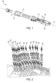
- Rod persuader 100 is configured to advance a fixation rod into a seated position in a polyaxial screw assembly. To advance the fixation rod into the seated position, rod persuader 100 is mounted onto a polyaxial screw assembly that is implanted in the vertebral body. Once rod persuader 100 is mounted onto the polyaxial screw assembly and over the fixation rod, a surgeon can use the rod persuader to advance the fixation rod down into the polyaxial screw assembly, where it can be locked in place to secure the vertebral body to the fixation rod.
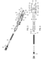
- FIG. 2 shows a spine fully instrumented with a series of rod persuaders 100 mounted to a series of polyaxial screw assemblies.
- Rod persuader 100 includes an elongated tubular housing 110.
- Housing 110 has a proximal housing end 112 and a distal housing end 114 opposite the proximal housing end.
- Housing 110 defines a longitudinal passage 111 extending between proximal housing end 112 and distal housing end 114.
- Housing 110 further defines a longitudinal axis 113 extending through longitudinal passage 111.
- Clamping assembly 120 includes a first arm 122 and a second arm 124.
- First and second arms 122, 124 are operable to clamp onto a polyaxial screw assembly.
- first and second arms 122, 124 are configured to clamp onto attachment features on a rod receiving component of a polyaxial screw assembly to secure rod persuader 100 to the polyaxial screw assembly.
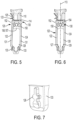
- first and second arms 122, 124 each have an irregularly shaped detent tab 126, as shown in FIG. 7 .
- Each detent tab 126 is configured to be detachably mounted into a similarly-shaped cut-out in a rod receiving component of a polyaxial screw assembly.
- first and second arms 122, 124 each have an offset or "dog leg” configuration.
- the dog leg configuration is defined by a rail section 131 and a detent section 133 laterally offset from the rail section.
- each detent sections 133 is positioned radially inwardly toward longitudinal axis 113, relative to its associated rail section 131.
- First and second arms 122, 124 form a gap 128 between them that creates a funnel or rod-centering structure, as will be explained.
- rod persuader 100 has a rod persuading assembly 130 that is operable to displace a fixation rod relative to a rod receiving component of a polyaxial screw assembly.
- Rod persuading assembly 130 includes an elongated shaft 140 coupled to an anchor 150.
- Shaft 140 is axially displaceable through housing 110 to axially displace anchor 150 relative to first and second arms 122, 124.
- Shaft 140 includes a proximal shaft end 142 and a distal shaft end 144.
- Distal shaft end 144 is coupled to anchor 150 in an axially fixed but rotatable connection 132.
- a variety of axially fixed but rotatable configurations can be used.
- distal shaft end 144 has an annular groove 145.
- a pair of pins 151 extend through holes in anchor 150 and reside in annular groove 145, one on each side of shaft 140, such that distal shaft end 144 is positioned between pins 151.
- pins 151 connect distal shaft end 144 to anchor 150 in an axially fixed connection that allows shaft 140 to rotate relative to anchor 150.
- rod persuader 100 When first and second arms 122, 124 are clamped onto the polyaxial screw assembly, rod persuader 100 is designed to apply force in the proximal direction on the polyaxial screw assembly via detent tabs 126, while applying distal force on the fixation rod via anchor 150. This has the effect of displacing the rod receiving component relative to the rod until the polyaxial screw assembly and the associated vertebral body are aligned with the rod.
- anchor 150 has a proximal end that defines a frame portion 152.
- Frame portion 152 forms a rectangular brace or sleeve 154 that surrounds first and second clamping arms 122, 124.
- a first flange 153 and a second flange 155 extend distally from sleeve 154 and parallel to one another.
- First flange 153 has a distal edge 156 with a concave curvature
- second flange 155 has a distal edge 157 with a concave curvature.
- Distal edges 156, 157 collectively form a rod engagement surface 158 configured to engage a rod at two locations.
- Rod persuader 100 features a first device configuration and a second device configuration that regulate how the rod persuading assembly 130 operates. These device configurations are illustrated in FIGS. 9 and 10 , and will be explained in greater detail in subsequent paragraphs.
- the first and second device configurations differ in how they permit axial movement of shaft 140 relative to housing 110.
- the first device configuration provides a mechanical advantage when needed to move shaft 140 in the distal direction.
- the first device configuration provides a ratcheting function that maintains the position of shaft 140 after the shaft is advanced in the distal direction.
- the second device configuration provides a freely movable arrangement for shaft 140 when mechanical advantage and ratcheting are not needed. The first and second device configurations will now be explained in more detail.
- rod persuading assembly 130 advances a fixation rod into a rod receiving component
- the rod can exert a significant amount of resistance to displacement and bear upwardly against anchor 150. Therefore, rod persuader 100 must be able to apply a significant amount of force against the rod to overcome the resistance against anchor 150 and displace the rod. Rod persuader 100 must also be able to maintain the advanced position of the rod after displacement and not allow any reverse movement in the proximal direction in response to resistance from the rod.
- the first device configuration which can apply a significant force against the rod by mechanical advantage, and maintain that force against the rod.
- the first device configuration allows axial displacement of shaft 140 relative to housing 110 to be controlled so that the shaft and anchor 150 can move distally as needed to advance the rod, while not move proximally in response to upward resistance from the rod.
- shaft 140 there is not a need to control axial displacement of shaft 140 relative to housing 110.
- free axial movement of shaft 140 can be desirable when rod persuader 100 is first being attached to a polyaxial screw assembly, or when the rod persuader is being removed from a polyaxial screw assembly after the fixation rod is locked in the polyaxial screw assembly by a locking element.
- Such freedom of movement in the axial direction is provided by the second device configuration, which allows shaft 140 and anchor 150 to move freely relative to housing 110 when strict control over axial displacement is not needed.
- the first and second device configurations are manually set by the user using a ratchet assembly 160.
- ratchet and “ratcheting”, as used herein, refer to any assembly in which two or more objects interface with one another by means of interlocking surfaces that allow relative movement in one direction but prevent movement in the opposite direction.
- ratchet or ratcheting assemblies include but are not limited to surfaces with helical threads, saw teeth, a combination of threads and saw teeth, or other projections that matingly engage one another.
- ratchet assembly 160 includes a first ratcheting block 162 and a second ratcheting block 164 that is diametrically opposed to the first ratcheting block relative to longitudinal axis 113.
- First and second ratcheting blocks 162, 164 have first ratchet surfaces 163, 165 respectively.
- Shaft 140 has a second ratchet surface 146.
- First ratchet surfaces 163, 165 are movable into and out of mating engagement with second ratchet surface 146 when the ratchet assembly is engaged and disengaged, respectively.
- First ratchet surfaces 163, 165 and second ratchet surface 146 each consist of a helical thread.
- first ratchet surfaces 163, 165 define a plurality of undercuts 167 separated by ramps 168.
- Second ratchet surface 146 defines a plurality of ledges 147 separated by inclined faces 148.
- the term "inclined”, as used in the context of the ratchet surfaces, refers to a surface that extends transversely to longitudinal axis 113 of housing 110.
- the shapes of ledges 147 and inclined faces 148 conform to the shapes of undercuts 167 and ramps 168.
- first and second ratcheting blocks 162, 164 are radially displaceable relative to longitudinal axis 113 between a ratcheting position and a release position.
- first ratchet surfaces 163, 165 mate with second ratchet surface 146.
- first ratchet surfaces 163, 165 are radially separated and disengaged from second ratchet surface 146.
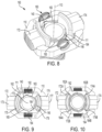
- FIG. 11 shows first ratchet surfaces 163, 165 mated with second ratchet surface 146 in the ratcheting position.
- the ledges 147 abut the undercuts 167 in an axial direction to prevent shaft 140 from moving in the proximal direction, i.e. away from the detent tabs 126.
- Ratchet assemblies according to the present disclosure can include one or more components for toggling ratcheting blocks 162, 164 between the ratcheting position and the release position.
- ratchet assemblies according to the present disclosure can include one or more buttons, levers, slides or other structures that displace ratcheting blocks 162, 164 into and out of engagement with one another.
- ratchet assembly 160 includes a first release button 172 and a second release button 174 diametrically opposed to the first release button relative to longitudinal axis 113.
- First release button 172 slidingly engages first ratcheting block 162 and second ratcheting block 164 to toggle the first ratcheting block and second ratcheting block between the ratcheting position and release position.
- Second release button 174 slidingly engages opposite sides of first ratcheting block 162 and second ratcheting block 164 to toggle the first ratcheting block and second ratcheting block between the ratcheting position and release position.
- FIG. 9 shows first and second release buttons 172, 174 engaging first and second ratcheting blocks 162, 164 in the ratcheting position. In this position, first and second release buttons 172, 174 are positioned farther apart, allowing first and second ratcheting blocks 162, 164 to be closer together and mate with shaft 140. This corresponds to the first device configuration mentioned above.
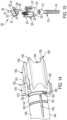
- FIG. 10 shows first and second release buttons 172, 174 engaging first and second ratcheting blocks 162, 164 in the release position. In this position, first and second release buttons 172, 174 are pressed radially inwardly and closer together, displacing ratcheting blocks 162, 164 radially outwardly and out of engagement with shaft 140. This corresponds to the second device configuration mentioned above.
- First release button 172 has a first portion 173 that projects outside of housing 110.
- First release button 172 also has a second portion 175 that extends into longitudinal passage 111 into engagement with first and second ratcheting blocks 162, 164.
- second release button 174 has a first portion 177 that projects outside of housing 110.
- Second release button 174 also has a second portion 179 that extends into longitudinal passage 111 into engagement with first and second ratcheting blocks 162, 164.
- Ratchet assembly 160 further includes a biasing mechanism 180 that biases first and second ratcheting blocks 162, 164 in the ratcheting position.
- Biasing mechanism 180 includes a first spring element 182 disposed between housing 110 and first ratcheting block 162 under stored energy.
- Biasing mechanism 180 also includes a second spring element 184 disposed between housing 110 and second ratcheting block 164 under stored energy.
- First and second spring elements 182, 184 exert biasing forces on first and second ratcheting blocks 162, 164 respectively to urge the ratcheting blocks toward the ratcheting position where they releasably engage shaft 140.
- first and second spring elements 182, 184 provide an auto-locking ratchet assembly in which the rod persuader is automatically returned to a ratcheting mode after first and second release buttons 172, 174 are released.
- First and second release buttons 172, 174 have respective edges that engage corresponding faces on first and second ratcheting blocks 162, 164.
- first release button 172 includes a first abutment edge 172A and a second abutment edge 172B.
- Second release button 174 includes a third abutment edge 174A and a fourth abutment edge 174B.
- First ratcheting block 162 has a first abutment face 162A that slidingly engages first abutment edge 172A, and a second abutment face 162B that slidingly engages third abutment edge 174A.
- second ratcheting block 164 has a third abutment face 164A that slidingly engages second abutment edge 172B, and a fourth abutment face 164B that slidingly engages fourth abutment edge 174B.
- Abutment edges 172A, 172B, 174A, 174B and abutment faces 162A, 162B, 164A, 164B are arranged relative to one another such that pressing first and/or second release buttons 172, 174 radially inwardly causes first and second ratcheting blocks 162, 164 to spread apart into the release position.
- first release button 172 can be depressed radially inwardly toward longitudinal axis 113.
- first release button 172 moves inwardly, it acts as a wedge between first and second ratcheting blocks 162, 164 and spreads them apart.
- second release button 174 can be depressed radially inwardly toward longitudinal axis 113.
- second release button 174 moves inwardly, it also acts as a wedge between first and second ratcheting blocks 162, 164 and spreads them apart. Therefore, pressing the first and/or second release buttons 172, 174 radially inwardly causes the first and second ratcheting blocks 162, 164 to move outwardly to the release position against the biasing forces of first and second spring elements 182, 184, respectively.
- first and second ratcheting blocks 162, 164 are in the ratcheting position, shown in FIG. 9 , second ratchet surface 146 on shaft 140 mates with first ratchet surfaces 163, 165 of first and second ratcheting blocks 162, 164, respectively.
- First ratcheting surfaces 163, 165 are helical thread segments as noted above.
- Second ratcheting surface 164 is a helical thread adapted to mate with the helical thread segments on the first ratcheting surfaces 163, 165.
- first and second ratcheting blocks 162, 164 and shaft 140 This creates a threaded engagement between first and second ratcheting blocks 162, 164 and shaft 140, in which the shaft is axially displaceable toward the proximal housing end 112 and toward distal housing end 114 in response to rotation of the shaft relative to housing 110.
- Shaft 140 is also axially displaceable toward the distal housing end 114 in response to axial force applied to shaft 110. However, shaft 140 is locked against axial displacement toward proximal housing end 112 in response to axial force.
- This one-way axial displacement can be appreciated from FIG. 11 , which shows the orientations of inclined faces 148 and ramps 168.
- the arrow "P” points in the proximal direction toward proximal end 112 of housing 110, and the arrow “D” points in the distal direction toward distal end 114 of the housing.
- the orientations of inclined faces 148 and ramps 168 are such that movement of shaft 140 in the distal direction causes the inclined faces to bear outwardly against the ramps.
- Shaft 140 can be axially displaced in the distal direction by manually applying a distal axial force on the shaft. This can be done in the first device configuration or in the second device configuration.
- first ratcheting surfaces 163, 165 and second ratcheting surface 164 are matingly engaged in the first device configuration, the inclined faces 148 push radially outwardly against the ramps 168 as shaft 140 moves in the distal direction relative to the ratcheting blocks 162, 164.
- ledges 147 move past undercuts 167 in the distal direction, ratcheting blocks 162, 164 snap back into mated engagement with shaft 140.
- first and second spring elements 182, 184 can be selected to provide a desired amount of resistance against outward displacement of ratcheting blocks 162, 164.
- the desired resistance can be selected so as to require a significant amount of axial force on shaft 140, thus preventing displacement of the shaft caused by inadvertent user contact with the shaft.
- This resistance to outward displacement of ratcheting blocks 162, 164 provides a mechanism for incremental advancement of anchor 150 in the distal direction which can be detected by an audible clicking sound each time the ratcheting blocks snap back into mating engagement with shaft 140.
- Rod persuaders according to the present disclosure can feature different arm configurations that attach to polyaxial screw assemblies.
- a rod persuader can have one arm mounted on a pivot hinge or other articulating joint that allows the arm to move relative to the housing.
- first arm 122 is connected to housing 110 by a hinge 123.
- Hinge 123 permits first arm 122 to pivot radially outwardly to an open position and radially inwardly to a closed position.
- Hinge 123 has a pivot spring element 125.
- Pivot spring element 125 which can be a torsion spring or other type of biasing element, is connected between housing 110 and first arm 122 under stored energy. The stored energy exerts a biasing force on first arm 122 that biases the first arm toward the closed position.
- First arm 122 is pivotable radially outwardly against the biasing force of pivot spring element 125 to an open position shown in FIG. 5 .
- first and second arms 122, 124 can be placed around a fixation rod and a rod receiver of a polyaxial screw assembly. Once the arms are placed around the fixation rod and rod receiver, first arm 122 can pivoted radially inwardly toward the longitudinal axis to a closed position shown in FIG. 6 . Once first arm 122 is in the closed position, the arms can be pressed into cutouts in the polyaxial screw assembly to lock rod persuader 100 to the polyaxial screw assembly.
- Rod persuaders according to the present disclosure can have one or more guiding structures that aid in aligning a fixation rod with the rod receiving channel of a polyaxial screw assembly. Often times, the rod persuader arms will be closed around a fixation rod, but the fixation rod will not be centered between the arms or aligned above the rod receiving channel of the polyaxial screw assembly.
- first and second arms 122, 124 include rod guiding surfaces.
- first arm 122 includes a first rod guiding surface 127 and second arm 124 includes a second rod guiding surface 129, as shown in FIG. 6 .
- First and second rod guiding surfaces 127, 129 include rounded sections that converge inwardly toward the longitudinal axis, forming a funnel or rod-centering structure.
- Concave distal edges 156, 157 of anchor 150 also provide a centering influence that guides the fixation rod to a centered position on longitudinal axis 113 so that the rod is received into the rod receiving component.
- Rod persuaders can also have mechanisms that reinforce the clamped connection between the first and second arms and the polyaxial screw assembly during rod persuasion.
- anchor 150 is axially displaceable along first and second arms 122, 124 between a proximal or raised position and a distal or lowered position.
- frame portion 152 In the raised position, frame portion 152 is positioned adjacent to distal housing end 114.
- frame portion 152 In the lowered position, frame portion 152 is positioned closer to detent tabs 126.
- the rectangular brace or sleeve 154 formed by frame portion 152 applies radially inward force on first and second arms 122, 124 and detent tabs 126 as anchor 150 is advanced toward the lowered position. This provides additional clamping force to reinforce the connection between rod persuader 100 and the polyaxial screw assembly.
- rod persuaders according to the present disclosure will be described in the following paragraphs. Many structural and functional features of rod persuaders in the examples that follow are similar or identical to those of rod persuader 100 and/or rod persuader 1000. Some of these common features will not be repeated for brevity, with the understanding that features shown in the Figures that correspond to features described in rod persuader 100 and/or rod persuader 1000 have the same description.
- Rod persuaders according to the present disclosure include features that allow the instrument to perform rod persuasion in conjunction with one or more other procedures, either at the same time that the rod persuasion is performed, or shortly before or after rod persuasion.
- This multi-functionality allows multiple procedures to be performed by one stand-alone instrument attached to the polyaxial screw assembly. This is advantageous because it avoids having to sterilize multiple instruments and keep them on hand at the operating table. It also avoids having to attach and detach multiple instruments to and from the polyaxial screw assembly during surgery.
- Rod persuader 1000 shown in FIG. 12 .
- Rod persuader 1000 is configured to reposition or reorient a vertebral body so that the vertebral body is aligned with a fixation rod, similar to rod persuader 100.
- rod persuader 1000 also has features that facilitate "polylocking" and spinal "derotation".
- Polylocking refers to a procedure that provisionally locks the position of a rod receiver relative to the position of a bone screw on a polyaxial screw assembly, without inserting a rod and locking screw (e.g. set screw) into the polyaxial screw assembly. This is performed as a temporary locking procedure that disables polyaxial rotation of the rod receiver about the head of the bone screw. Once polylocking is performed, the bone screw and rod receiver form a singular fixed construct, allowing adjustment force to be applied to both the rod receiver and bone screw in unison.
- a rod and locking screw e.g. set screw
- Derotation refers to a procedure for correcting abnormal spinal curvatures.
- one or more instruments are used to apply bending moments to one or more polyaxial screw assemblies implanted in vertebral bodies.
- a bending moment induces rotational and translational movement of a vertebral body relative to adjacent bodies.
- Rotational and translational movement of vertebral bodies can be done in a coordinated manner to adjust the spinal curvature.
- Rod persuader 1000 includes an elongated housing 1100 that defines a longitudinal passage 1110.
- An exterior portion of housing 1100 includes a grooved section 1105 configured to mate with couplers and counter-torque instruments.
- Housing 1100 also has a clamping assembly 1200 for attaching the housing to a polyaxial screw assembly.
- Clamping assembly 1200 includes a first arm 1220 and a second arm 1240 individually operable to clamp onto a polyaxial screw assembly and detach from a polyaxial screw assembly.
- First and second arms 1220, 1240 each define elongated apertures and include pivot arms that are pivotably mounted in the apertures.
- Clamping assemblies with pivot arms that can be used according to the present disclosure include, but are not limited to, the assemblies described in U.S. Application Serial No. 16/371,836
- first arm 1220 includes a first pivot arm 1222 pivotably mounted in a first aperture 1224.
- Second arm 1240 includes a second pivot arm 1242 pivotably mounted in a second aperture 1244.
- First and second pivot arms 1222, 1242 are each pivotable between an attachment position and a release position. In the attachment position, first and second pivot arms 1222, 1242 are pivoted radially inwardly toward one another and into a position to attach rod persuader 1000 to an engagement structure, such as a bore, slot, cut-out or other type of void, on a polyaxial screw assembly. In the release position, first and second pivot arms 1222, 1242 are pivoted radially outwardly and away from one another to disengage the engagement structure on the polyaxial screw assembly.
- First and second pivot arms 1222, 1242 are each biased toward their respective attachment position by biasing elements that engage proximal ends of each pivot arm.
- Biasing elements may be in the form of leaf springs, wave springs, torsion springs, coil springs, spring washers and other biasing elements that store and release energy upon application and removal of force.
- rod persuader 1000 further includes a rod persuading assembly 1300.
- Rod persuading assembly 1300 includes a shaft 1400 coupled to an anchor 1500.
- Shaft 1400 has a distal end 1440 that defines diametrically opposed slots 1442 extending in an axial direction. Slots 1442 thus divide distal end 1440 into distal end segments 1441.
- a circumferential groove 1450 extends around the exterior of distal end segments 1441.
- Anchor 1500 has a proximal end 1502 defining a socket 1503 adapted to receive distal end segments 1441 of shaft 1400.
- Socket 1503 forms an annular rim 1505 that extends radially inwardly toward the center of the socket, forming a reduced diameter section at the opening into the socket.
- the inner diameter of socket 1503 inside rim 1505 is smaller than the outer diameter of distal end segments 1441 of shaft 1400 when the distal end segments are relaxed.
- the inner diameter of socket 1503 inside rim 1505 is substantially equal to or slightly larger than the outer diameter of distal end segments 1441 inside circumferential groove 1450, however.
- Distal end segments 1441 are configured to act as leaf springs that bend or converge toward one another in response to radial compression when the distal end segments are inserted through rim 1505 into socket 1503. As distal end segments 1441 advance past rim 1505, the distal end segments are compressed inwardly toward one another into slots 1442 and remain compressed under stored energy. When circumferential groove 1450 aligns with rim 1505, the distal end segments 1441 release the stored energy and snap radially outwardly so that the rim becomes captured inside the circumferential groove. Walls inside circumferential groove 1450 prevent further axial movement of shaft 1400 relative to socket 1503 in either a proximal or distal direction. Therefore, circumferential groove 1450 lockingly engages rim 1505 to couple shaft 1400 to anchor 1500.
- Rim 1505 and circumferential groove 1450 form an axially fixed, rotatable coupling 1510.
- the orientation of anchor 1500 is fixed relative to the orientation of housing 1100 due to alignment features and anti-splaying elements which will be described.
- the orientation of shaft 1400 is not fixed relative to housing 1100, however. As such, shaft 1400 is permitted to rotate relative to housing 1100 and anchor 1500 to axially displace the anchor in longitudinal passage 1110, while the orientation of the anchor remains unchanged.
- Anchors according to the present disclosure can include one or more polylockinq features configured to provisionally lock a rod receiver relative to the head of a polyaxial screw assembly.
- U.S. Application Serial No. 16/371,836 describes polyaxial screw assemblies and polylocking features that can be used with rod persuaders of the present disclosure.
- Anchor 1500 includes a distal end 1504 with polylocking features that are configured to provisionally lock polyaxial screw assembly 300.
- Polyaxial screw assembly 300 includes a polyaxial bone screw 310 with a spherical shaped screw head 312 and threaded shank 314, as shown in FIG. 15 .
- Bone screw 310 is configured to be received in rod receiver 320.
- Rod receiver 320 has an upper portion 322 that defines a U-shaped channel 323 to receive an elongated fixation element, such as a spinal rod.
- Rod receiver 320 also has a lower portion 324 that defines a seat 326 in its interior and a through-hole 328.
- Seat configurations can have various geometries, such as a spherical or conical shape. In the present example, seat 326 is conical.
- Through-hole 328 has a diameter that is smaller than the diameter of screw head 312.
- Rod receiver 320 is therefore configured to receive bone screw 320 in a seated arrangement, with screw head 312 seated in conical seat 326, and with threaded shank 314 projecting out of through-hole 328.
- Rod receiver 320 has a pair of diametrically opposed cut-outs 321 that are open on the exterior of the rod receiver, and that extend into the wall of the rod receiver. Cut-outs 321 have irregular shapes that conform to the irregular shapes of locking tabs provided on first and second pivot arms 1222, 1242 of rod persuader 1000.
- Polyaxial screw assembly 300 also includes an insert 330.
- Insert 330 has an upper portion 332 that defines a U-shaped recess 334 to receive an elongated fixation element, such as a spinal rod.
- Insert 330 also has a lower portion 336 with a spherical shaped concavity 338.
- insert 330 is positioned in rod receiver 320 in a position proximal to screw head 312. In this position, recess 334 is positioned to receive an elongated fixation element, such as a spinal rod, and concavity 338 is positioned to bear against and frictionally engage screw head 312.
- Distal end 1504 of anchor 1500 includes four pusher posts 1536, as seen in FIG. 14 .
- Pusher posts 1536 are configured to apply axial force to insert 330 when anchor 1500 is advanced into rod receiver 320 and provisionally lock the position of the rod receiver relative to the screw head 312.
- Each pusher post 1536 is positioned to engage a landing 331 on the top of insert 320, as shown in FIG. 16 .
- Axial force on landings 331 compresses insert 330 into frictional engagement with screw head 312 of bone screw 310. The frictional engagement is sufficient to stabilize the rod receiver 320 on screw head 310 so that the rod receiver does not pivot or "flop" on the bone screw.
- Anchors according to the present disclosure can also include one or more features that prevent splaying from occurring, i.e. anti-splaying features.
- the term "splaying”, as used herein, refers to an outward deflection of clamping arms or pivot arms of a housing when another instrument is advanced through the housing. Splaying is undesirable because it can cause the clamping arms or pivot arms to disconnect from the polyaxial screw assembly, interrupting a surgical procedure.
- an "anti-splaying" feature refers to any feature that holds clamping arms or pivot arms in their locked positions on a rod receiver and prevents the arms from splaying.
- proximal end 1502 of anchor 1500 has a first pair of anti-splaying features in the form of locking rails 1550.
- Each locking rail 1550 has a T-shaped body 1570 comprising a stem portion 1572 that extends outwardly from anchor 1500 and a flange portion 1574 that extends generally perpendicular to stem portion 1572.
- first pivot arm 1222 and second pivot arm 1242 will now be described in more detail with reference to FIGS. 17A-17C .
- First and second pivot arms 1222, 1224 are identically configured. Therefore, the features of first pivot arm 1222 will be described with the understanding that identical features are present on second pivot arm 1224.
- First pivot arm 1222 defines a dog leg section 1245 and an anti-splaying slot 1250.
- Each anti-splaying slot 1250 forms an aperture 1252 in its respective dog leg section 1245.
- Each aperture 1252 is adapted to axially receive one of the locking rails 1550 (shown in FIG. 14 ) and allow the locking rail to slide axially to the distal end of the pivot arm.
- Anti-splaying slots 1250 also define openings 1255 that are open to longitudinal passage 1110. Openings 1255 receive stem portions 1572 of locking rails 1550 when the locking rails are inserted into the first and second pivot arms 1222, 1242.
- Locking rails 1550 are axially positioned on anchor 1500 so that when the anchor is advanced as far as possible into a polyaxial screw assembly to engage an insert, the locking rails maintain pivot arms 1222, 1242 in a straight configuration with their locking tabs firmly fixed in cut-outs or other engagement features on the rod receiver. This prevents the distal ends of pivot arms 1222, 1242 from splaying or bending outwardly and disengaging from the polyaxial screw assembly.
- FIG. 18 shows a rod persuader 2000 according to another embodiment of the disclosure.
- Rod persuader 2000 is substantially identical to rod persuader 1000 but has a shorter axial length than rod persuader 1000.
- rod persuader 2000 does not have the grooved section 1105 configured to mate with couplers and counter-torque instruments.
- the shorter axial length of rod persuader 2000 is beneficial when many rod persuaders are attached to the spine at the same time. The shorter lengths reduce the stress on the spine caused by the combined weight of multiple instruments. In addition, the shorter lengths result in fewer visual obstructions above the spine.
- FIG. 19 shows a rod persuader 3000 according to another embodiment of the disclosure.
- Rod persuader 3000 is similar to rod persuader 1000, but has a different vertebral anchor clamping assembly 3120.
- Clamping assembly 3120 includes first and second sleeve portions 3121, 3123. This arrangement provides a wider opening and connection mechanism that can be lowered more easily onto a polyaxial screw assembly.
- a first clamping arm 3122 is pivotably mounted in first sleeve portion 3121, and a second clamping arm 3124 is pivotably mounted in second sleeve portion 3123.
- Rod persuader 3000 also has a rod persuader assembly 3130 featuring an anchor 3150 with two anchor plates 3152. Anchor plates 3152 are axially displaceable on either side of first and second sleeve portions 3121, 3123.
- Rod persuader assembly 3130 also includes a shaft 3140 with anti-splaying features in the form of locking rails 3550, one of which is visible extending in an anti-splaying slot 3250 in first clamping arm 3122.
- Rod persuader 4000 has an elongated shaft 4400 that is similar to the shafts of the previous examples, but the shaft features a linear arrangement of ratchet teeth 4600 that follow a saw tooth configuration (i.e. a series of separate circumferential teeth) rather than a helical thread arrangement (i.e. one continuous helical thread).
- This saw tooth configuration can provide controlled shaft displacement and free shaft displacement like a helical thread, and may be desirable where mechanical advantage is not a requirement.
- an elongated shaft 5400 is shown according to another example.
- Shaft 5400 is similar to the shafts of the previous examples, but combines a first set of ratchet teeth 5600 having a helical thread arrangement with a second set of ratchet teeth 5700 having a saw tooth configuration.
- This configuration provides a controlled, one-way shaft displacement with mechanical advantage up to a certain point.
- first set of ratchet teeth 5600 can engage the ratchet blocks to allow the shaft to be driven via the threaded engagement under mechanical advantage.
- the ratchet blocks can engage the second set of ratchet teeth 5700 to continue advancement.
- first and second sets of ratchet teeth 5600, 5700 can be reversed, such that the ratchet blocks initially engage the ratchet teeth with a saw tooth configuration before engaging ratchet teeth with a thread arrangement.
- the two ratchet teeth configurations can be used in any combination, with the sections having the same axial length or different axial lengths so as to apply appropriate forces for a given application.
- ratchet assembly need not have a pair of ratcheting blocks that control movement of the shaft and anchor, but could feature a ratchet assembly with a single ratcheting block that engages the shaft on one side of the longitudinal axis.
- the ratchet assembly could have three or more ratcheting blocks that are arranged around the shaft.
- the ratchet assembly need not have a pair of diametrically opposed buttons that toggle the ratchet assembly between the release position and ratcheting position, but could feature a single button acting as a wedge between two ratcheting blocks. Therefore, rod persuaders according to the present disclosure can feature any number of ratcheting blocks and release structures, and are not limited to the examples shown.
Landscapes
- Health & Medical Sciences (AREA)
- Orthopedic Medicine & Surgery (AREA)
- Neurology (AREA)
- Life Sciences & Earth Sciences (AREA)
- Surgery (AREA)
- Heart & Thoracic Surgery (AREA)
- Engineering & Computer Science (AREA)
- Biomedical Technology (AREA)
- Nuclear Medicine, Radiotherapy & Molecular Imaging (AREA)
- Medical Informatics (AREA)
- Molecular Biology (AREA)
- Animal Behavior & Ethology (AREA)
- General Health & Medical Sciences (AREA)
- Public Health (AREA)
- Veterinary Medicine (AREA)
- Surgical Instruments (AREA)
Claims (24)
- instrument de contrainte (100 ; 1000) pour faire avancer une tige de fixation dans un canal de réception de tige d'un implant vertébral, l'instrument de contrainte (100 ; 1000) comprenant :un boîtier (110 ; 1100) comprenant une extrémité proximale de boîtier (112) et une extrémité distale de boîtier (114), le boîtier (110 ; 1100) définissant un passage longitudinal (111 ; 1110) s'étendant entre l'extrémité proximale de boîtier (112) et l'extrémité distale du boîtier (114), le boîtier (110 ; 1100) définissant en outre un axe longitudinal (113) s'étendant à travers le passage longitudinal (111 ; 1110) ;un premier bras (122 ; 1222) et un second bras (124 ; 1242), les premier et second bras (122, 124; 1222, 1242) comprenant des crans (126) configurés pour une liaison amovible à l'implant vertébral ;un ancrage (150 ; 1500) comprenant une surface de mise en prise de tige de fixation ;un arbre (140; 1400) comprenant une extrémité d'arbre proximale (142) et une extrémité d'arbre distale (144), l'extrémité d'arbre distale (144) étant couplée à l'ancrage (150 ; 1500) dans une liaison axialement fixe mais rotative, avec l'arbre (140 ; 1400) pouvant être déplacé axialement à travers le passage longitudinal (111 ; 1110) du boîtier (110 ; 1100) pour déplacer axialement l'ancrage (150 ; 1500) ; etun ensemble cliquet à verrouillage automatique (160) en prise libérable avec l'arbre (140 ; 1400), l'ensemble cliquet à verrouillage automatique (160) permettant de commander un déplacement axial de l'arbre (140; 1400) à travers le passage longitudinal (111 ; 1110) du boîtier (110 ; 1100) ;dans lequel l'ancrage (150 ; 1500) comprend un ou plusieurs éléments anti-écartement ;le premier bras (122 ; 1222) et le second bras (124 ; 1242) comprennent une ou plusieurs caractéristiques anti-écartement qui coopèrent avec les un ou plusieurs éléments anti-écartement (1550) de l'ancrage (150 ; 1500) ;caractérisé en ce queune extrémité proximale (1502) de l'ancrage (1500) présente une première paire d'éléments anti-écartement sous la forme de rails de verrouillage (1550), dans lequel chaque rail de verrouillage (1550) présente un corps en forme de T (1570) comprenant une partie tige (1572) qui s'étend vers l'extérieur à partir de l'ancrage (1500), et une partie bride (1574) qui s'étend perpendiculairement à la partie tige (1572) ;les premier et second bras pivotants (1222, 1224) étant configurés de manière identique et définissant chacun une section de patte de chien (1245) et une fente anti-écartement (1250) en tant que caractéristiques anti-écartement ;chaque fente anti-écartement (1250) forme un orifice (1252) dans sa section de patte de chien respective (1245), chaque orifice (1252) étant adapté pour recevoir axialement l'un des rails de verrouillage (1550) et pour permettre au rail de verrouillage (1550) de coulisser axialement vers l'extrémité distale des premier et second bras pivotants (1222, 1242) respectifs ;les fentes anti-écartement (1250) définissent des ouvertures (1255) qui sont ouvertes sur un passage longitudinal (1110) et configurées pour recevoir des parties tige (1572) des rails de verrouillage (1550) lorsque les rails de verrouillage (1550) sont insérés dans les premier et second bras pivotants (1222, 1242),les rails de verrouillage (1550) sont positionnés axialement sur l'ancrage (1500) de telle sorte que, lorsque l'ancrage (1500) est avancé aussi loin que possible dans un ensemble vis polyaxiale pour venir en prise avec l'insert vertébral, les rails de verrouillage (1550) maintiennent les premier et second bras pivotants (1222, 1242) dans une configuration droite avec des pattes de verrouillage de ceux-ci fermement fixées dans des découpes ou d'autres caractéristiques de mise en prise sur un récepteur de tige.
- instrument de contrainte (100 ; 1000) selon la revendication 1, dans lequel l'ensemble cliquet à verrouillage automatique (160) comprend au moins un bloc d'encliquetage (162, 164) qui vient en prise de manière libérable avec l'arbre (140 ; 1400).
- instrument de contrainte (100 ; 1000) selon la revendication 2, dans lequel le au moins un bloc d'encliquetage (162, 164) comprend une première surface de cliquet (163, 165) et l'arbre (140 ; 1400) comprend une seconde surface de cliquet (146) en prise libérable avec la première surface de cliquet (163, 165).
- instrument de contrainte (100 ; 1000) selon la revendication 3, dans lequel l'une de la première surface de cliquet (163, 165) et de la seconde surface de cliquet (146) comprend une pluralité de rebords (147) séparés par des faces inclinées (148), et l'autre de la première surface de cliquet (163, 165) et de la seconde surface de cliquet (146) comprend une pluralité de contre-dépouilles (167) séparées par des rampes (168).
- instrument de contrainte (100 ; 1000) selon la revendication 4, dans lequel le au moins un bloc d'encliquetage (162, 164) peut être déplacé radialement par rapport à l'axe longitudinal (113) entre une position d'encliquetage dans laquelle la première surface de cliquet (163, 165) vient en prise par accouplement avec la seconde surface de cliquet (146), et une position de libération, dans laquelle la première surface de cliquet (163, 165) est radialement séparée et désolidarisée de la seconde surface de cliquet (146).
- instrument de contrainte (100 ; 1000) selon la revendication 5, dans lequel la pluralité de rebords (147) butent axialement sur la pluralité de contre-dépouilles (167) lorsque le au moins un bloc d'encliquetage (162, 164) est dans la position d'encliquetage pour empêcher l'arbre (140 ; 1400) de se déplacer vers l'extrémité proximale de boîtier (112).
- instrument de contrainte (100 ; 1000) selon la revendication 5, dans lequel l'ensemble cliquet à verrouillage automatique comprend au moins un bouton de libération (172, 174), le au moins un bouton de libération (172, 174) étant en prise coulissante avec le au moins un bloc d'encliquetage (162, 164) pour faire basculer le au moins un bloc d'encliquetage (162, 164) entre la position d'encliquetage et la position de libération.
- instrument de contrainte (100 ; 1000) selon la revendication 7, comprenant en outre au moins un élément à ressort (182, 184) en prise avec le au moins un bloc d'encliquetage (162, 164), le au moins un élément à ressort (182, 184) étant disposé entre le boîtier (110 ; 1100) et le au moins un bloc d'encliquetage (162, 164) sous l'effet d'une énergie stockée qui exerce une force de sollicitation sur le au moins un bloc d'encliquetage (162, 164) pour pousser le au moins un bloc d'encliquetage (162, 164) vers la position d'encliquetage.
- instrument de contrainte (100 ; 1000) selon la revendication 8, dans lequel le au moins un bouton de libération (172, 174) peut se déplacer vers une position enfoncée pour déplacer le au moins un bloc d'encliquetage (162, 164) vers la position de libération contre la force de sollicitation de l'élément à ressort (182, 184).
- Instrument de contrainte (100 ; 1000) selon la revendication 7, dans lequel le au moins un bouton de libération (172, 174) comprend une première surface de butée et le au moins un bloc d'encliquetage (162, 164) comprend une seconde surface de butée qui vient en prise de manière coulissante avec la première surface de butée.
- instrument de contrainte (100 ; 1000) selon la revendication 7, dans lequel le au moins un bouton de libération (172, 174) présente une première partie qui fait saillie à l'extérieur du boîtier (110 ; 1100), et une seconde partie qui s'étend dans le passage longitudinal (111 ; 1110) en prise avec le au moins un bloc d'encliquetage (162, 164).
- instrument de contrainte (100 ; 1000) selon la revendication 5, dans lequel, lorsque le au moins un bloc d'encliquetage (162, 164) est dans la position d'encliquetage, l'arbre (140 ; 1400) peut être déplacé axialement vers l'extrémité proximale (112) du boîtier (110 ; 1100) et vers l'extrémité distale (114) du boîtier (110 ; 1100) à la suite d'une rotation de l'arbre (140 ; 1400) par rapport au boîtier (110 ; 1100).
- instrument de contrainte (100 ; 1000) selon la revendication 5, dans lequel, lorsque le au moins un bloc d'encliquetage (162, 164) est dans la position d'encliquetage, l'arbre (140 ; 1400) peut être déplacé axialement vers l'extrémité distale de boîtier (114) en réponse à une force axiale appliquée à l'arbre (140 ; 1400), mais est verrouillé contre un déplacement axial vers l'extrémité proximale de boîtier (112) en réponse à une force axiale.
- instrument de contrainte (100 ; 1000) selon la revendication 3, dans lequel les première et seconde surfaces de cliquet (163, 165 ; 146) comprennent des filetages (5600).
- instrument de contrainte (100 ; 1000) selon la revendication 3, dans lequel les première et seconde surfaces de cliquet (163, 165 ; 146) comprennent des dents de cliquet (4600) qui suivent une configuration en dents de scie.
- instrument de contrainte (100 ; 1000) selon la revendication 3, dans lequel les première et seconde surfaces de cliquet (163, 165 ; 146) comprennent chacune une première section présentant des filetages (5600) et une seconde section présentant des dents de cliquet (5700) qui suivent une configuration en dents de scie.
- instrument de contrainte (100 ; 1000) selon la revendication 1, dans lequel au moins l'un des premier et second bras (122, 124; 1222, 1242) peut pivoter radialement vers l'extérieur depuis l'axe longitudinal (113) jusqu'à une position ouverte, et peut pivoter radialement vers l'intérieur vers l'axe longitudinal (113) jusqu'à une position fermée.
- instrument de contrainte (100 ; 1000) selon la revendication 16, dans lequel ledit au moins un des premier et second bras (122, 124 ; 1222, 1242) est relié au boîtier (110 ; 1100) par une charnière (123) comprenant un élément à ressort pivotant (125), l'élément à ressort pivotant (125) étant relié entre le boîtier (110 ; 1100) et ledit au moins un des premier et second bras (122, 124 ; 1222, 1242) sous l'effet de l'énergie stockée qui sollicite ledit au moins l'un des premier et second bras (122, 124 ; 1222, 1242) vers la position fermée.
- instrument de contrainte (100 ; 1000) selon la revendication 1, dans lequel le premier bras (122 ; 1222) comprend une première surface de guidage de tige (127) et le second bras (124; 1242) comprend une second surface de guidage de tige (129), les première et seconde surfaces de guidage de tige (127, 129) convergeant vers l'intérieur vers l'axe longitudinal (113).
- instrument de contrainte (100 ; 1000) selon la revendication 19, dans lequel les première et seconde surfaces de guidage de tige (127, 129) comprennent des sections arrondies.
- instrument de contrainte (100 ; 1000) selon la revendication 1, dans lequel l'ancrage (150 ; 1500) comprend une partie cadre (152) agencée autour des premier et second bras (122, 124 ; 1222, 1242).
- instrument de contrainte (100 ; 1000) selon la revendication 21, dans lequel l'ancrage (150 ; 1500) peut être déplacé axialement entre une position relevée et une position abaissée, la partie cadre (152) étant positionnée plus près des crans (126) dans la position abaissée pour appliquer une force de serrage radialement vers l'intérieur aux extrémités distales des premier et second bras (122, 124 ; 1222, 1242).
- instrument de contrainte (100 ; 1000) selon la revendication 21, dans lequel les premier et second bras (122, 124 ; 1222, 1242) comprennent des parties rails sur lesquelles la partie cadre (152) de l'ancrage (150 ; 1500) est agencée de manière coulissante, et des parties crans (133) qui comprennent les crans (126), les parties crans (133) étant agencées radialement vers l'intérieur par rapport aux parties rails.
- instrument de contrainte (100 ; 1000) selon la revendication 1, dans lequel l'ancrage (150 ; 1500) comprend une ou plusieurs caractéristiques de polyverrouillage.
Applications Claiming Priority (1)
| Application Number | Priority Date | Filing Date | Title |
|---|---|---|---|
| US16/513,082 US11553947B2 (en) | 2019-07-16 | 2019-07-16 | Spinal deformity sequential persuader |
Publications (2)
| Publication Number | Publication Date |
|---|---|
| EP3766444A1 EP3766444A1 (fr) | 2021-01-20 |
| EP3766444B1 true EP3766444B1 (fr) | 2024-08-28 |
Family
ID=71661664
Family Applications (1)
| Application Number | Title | Priority Date | Filing Date |
|---|---|---|---|
| EP20186122.6A Active EP3766444B1 (fr) | 2019-07-16 | 2020-07-16 | Persuadeur séquentiel de difformité rachidienne |
Country Status (3)
| Country | Link |
|---|---|
| US (1) | US11553947B2 (fr) |
| EP (1) | EP3766444B1 (fr) |
| ES (1) | ES2992448T3 (fr) |
Families Citing this family (1)
| Publication number | Priority date | Publication date | Assignee | Title |
|---|---|---|---|---|
| WO2022184798A1 (fr) * | 2021-03-05 | 2022-09-09 | Medos International Sarl | Réducteur séquentiel |
Family Cites Families (114)
| Publication number | Priority date | Publication date | Assignee | Title |
|---|---|---|---|---|
| US5683391A (en) | 1995-06-07 | 1997-11-04 | Danek Medical, Inc. | Anterior spinal instrumentation and method for implantation and revision |
| US5782830A (en) | 1995-10-16 | 1998-07-21 | Sdgi Holdings, Inc. | Implant insertion device |
| EP0834280B1 (fr) | 1996-10-04 | 2004-01-02 | United States Surgical Corporation | Appareil d'implantation d'un élément de fixation de tissus |
| US5720751A (en) | 1996-11-27 | 1998-02-24 | Jackson; Roger P. | Tools for use in seating spinal rods in open ended implants |
| US5910141A (en) | 1997-02-12 | 1999-06-08 | Sdgi Holdings, Inc. | Rod introduction apparatus |
| US5964769A (en) | 1997-08-26 | 1999-10-12 | Spinal Concepts, Inc. | Surgical cable system and method |
| GB9804473D0 (en) | 1998-03-02 | 1998-04-29 | Benoist Girard & Cie | Prosthesis inserter |
| DE29806563U1 (de) | 1998-04-09 | 1998-06-18 | Howmedica GmbH, 24232 Schönkirchen | Pedikelschraube und Montagehilfe dafür |
| US5911722A (en) | 1998-07-23 | 1999-06-15 | Millenium Devices Llc | Leban/Gordon surgical hand driver |
| US7862587B2 (en) | 2004-02-27 | 2011-01-04 | Jackson Roger P | Dynamic stabilization assemblies, tool set and method |
| US6440133B1 (en) | 2001-07-03 | 2002-08-27 | Sdgi Holdings, Inc. | Rod reducer instruments and methods |
| US6746449B2 (en) | 2001-09-12 | 2004-06-08 | Spinal Concepts, Inc. | Spinal rod translation instrument |
| US6660006B2 (en) | 2002-04-17 | 2003-12-09 | Stryker Spine | Rod persuader |
| US7278995B2 (en) | 2002-06-04 | 2007-10-09 | Howmedica Osteonics Corp. | Apparatus for securing a spinal rod system |
| US20060095035A1 (en) | 2004-11-03 | 2006-05-04 | Jones Robert J | Instruments and methods for reduction of vertebral bodies |
| US7887539B2 (en) | 2003-01-24 | 2011-02-15 | Depuy Spine, Inc. | Spinal rod approximators |
| US7621918B2 (en) | 2004-11-23 | 2009-11-24 | Jackson Roger P | Spinal fixation tool set and method |
| US7291152B2 (en) | 2003-04-18 | 2007-11-06 | Abdou M Samy | Bone fixation system and method of implantation |
| US7156849B2 (en) | 2003-06-16 | 2007-01-02 | Depuy Spine, Inc. | Rod reduction nut and driver tool |
| US20040267275A1 (en) | 2003-06-26 | 2004-12-30 | Cournoyer John R. | Spinal implant holder and rod reduction systems and methods |
| US7648507B2 (en) | 2003-12-16 | 2010-01-19 | Depuy Acromed, Inc. | Pivoting implant holder |
| US7648506B2 (en) | 2003-12-16 | 2010-01-19 | Depuy Acromed, Inc. | Pivoting implant holder |
| BRPI0417670A (pt) | 2003-12-17 | 2007-04-03 | Depuy Spine Inc | instrumentos e métodos para acoplamento de áncora óssea e redução de haste espinhal |
| US7842044B2 (en) | 2003-12-17 | 2010-11-30 | Depuy Spine, Inc. | Instruments and methods for bone anchor engagement and spinal rod reduction |
| FR2863861B1 (fr) | 2003-12-23 | 2006-03-17 | Eurosurgical | Instrument chirurgical de type declipseuse pour implant rachidien. |
| US7611517B2 (en) | 2004-02-27 | 2009-11-03 | Warsaw Orthopedic, Inc. | Rod reducer |
| US7470279B2 (en) | 2004-02-27 | 2008-12-30 | Jackson Roger P | Orthopedic implant rod reduction tool set and method |
| US8152810B2 (en) | 2004-11-23 | 2012-04-10 | Jackson Roger P | Spinal fixation tool set and method |
| US7160300B2 (en) | 2004-02-27 | 2007-01-09 | Jackson Roger P | Orthopedic implant rod reduction tool set and method |
| JP2007525274A (ja) | 2004-02-27 | 2007-09-06 | ロジャー・ピー・ジャクソン | 整形外科インプラントロッド整復器具セット及び方法 |
| JP4213609B2 (ja) | 2004-03-09 | 2009-01-21 | 昭和医科工業株式会社 | ロッド固定用補助器具 |
| US7491207B2 (en) | 2004-04-12 | 2009-02-17 | Synthes Usa, Llc | Rod persuader |
| US7572281B2 (en) | 2004-08-06 | 2009-08-11 | Depuy Spine, Inc. | Instrument for guiding a rod into an implant in a spinal fixation system |
| US7462182B2 (en) | 2004-08-10 | 2008-12-09 | Warsaw Orthopedic, Inc. | Reducing instrument for spinal surgery |
| US7651502B2 (en) | 2004-09-24 | 2010-01-26 | Jackson Roger P | Spinal fixation tool set and method for rod reduction and fastener insertion |
| US7569061B2 (en) | 2004-11-16 | 2009-08-04 | Innovative Spinal Technologies, Inc. | Off-axis anchor guidance system |
| US7608081B2 (en) | 2005-05-23 | 2009-10-27 | Custom Spine, Inc. | Rod reducer |
| US7771430B2 (en) | 2005-09-29 | 2010-08-10 | K2M, Inc. | Single action anti-torque rod reducer |
| US7520879B2 (en) | 2006-02-07 | 2009-04-21 | Warsaw Orthopedic, Inc. | Surgical instruments and techniques for percutaneous placement of spinal stabilization elements |
| US7931654B2 (en) | 2006-03-09 | 2011-04-26 | K2M, Inc. | Dual action rod reducing and locking device and method |
| US7922749B2 (en) | 2006-04-14 | 2011-04-12 | Warsaw Orthopedic, Inc. | Reducing device |
| US8192438B2 (en) | 2006-05-18 | 2012-06-05 | Phygen, LLC. | Rod reducer |
| US8679128B2 (en) | 2006-12-07 | 2014-03-25 | Zimmer Spine, Inc. | Apparatus and methods for reduction of vertebral bodies in a spine |
| JP2010512178A (ja) | 2006-12-08 | 2010-04-22 | ロジャー・ピー・ジャクソン | 動的脊椎インプラントのためのツールシステム |
| US20080228233A1 (en) * | 2007-02-12 | 2008-09-18 | Jeffrey Hoffman | Instrument for manipulating spinal implant system |
| US8308774B2 (en) | 2007-02-14 | 2012-11-13 | Pioneer Surgical Technology, Inc. | Spinal rod reducer and cap insertion apparatus |
| US8172847B2 (en) | 2007-03-29 | 2012-05-08 | Depuy Spine, Inc. | In-line rod reduction device and methods |
| US8961523B2 (en) | 2007-07-13 | 2015-02-24 | K2M, Inc. | Rod reduction device and method of use |
| US20090030420A1 (en) | 2007-07-26 | 2009-01-29 | Depuy Spine, Inc. | Spinal rod reduction instruments and methods for use |
| US8540718B2 (en) | 2007-10-23 | 2013-09-24 | Aesculap Implant Systems, Llc | Rod persuader |
| US8439922B1 (en) | 2008-02-06 | 2013-05-14 | NiVasive, Inc. | Systems and methods for holding and implanting bone anchors |
| US8608746B2 (en) | 2008-03-10 | 2013-12-17 | DePuy Synthes Products, LLC | Derotation instrument with reduction functionality |
| US8764754B2 (en) | 2008-03-21 | 2014-07-01 | Life Spine, Inc. | Systems and methods for spinal rod insertion and reduction |
| US8142436B2 (en) | 2008-06-06 | 2012-03-27 | X-Spine Systems, Inc. | Retraction tube for use with bone screw |
| JP5543964B2 (ja) | 2008-06-11 | 2014-07-09 | ケー2エム, インコーポレイテッド | ロッド整復装置 |
| EP2296569B1 (fr) | 2008-06-11 | 2014-04-09 | K2M, Inc. | Dispositif de réduction de tige |
| WO2009158707A1 (fr) | 2008-06-27 | 2009-12-30 | K2M, Inc. | Système et procédé de réalisation d'une chirurgie vertébrale |
| BRPI0916992A2 (pt) | 2008-09-12 | 2015-11-24 | Synthes Gmbh | ferramenta de redução |
| FR2937855B1 (fr) | 2008-11-05 | 2010-12-24 | Warsaw Orthopedic Inc | Instrument d'introduction progressive d'une tige vertebrale. |
| US8864767B2 (en) | 2008-11-10 | 2014-10-21 | Spinal Elements, Inc. | Rod reducer instrument for spinal surgery |
| CN102256558A (zh) | 2008-12-17 | 2011-11-23 | 斯恩蒂斯有限公司 | 用于脊柱矫正手术的杆复位器装置 |
| US8900238B2 (en) | 2009-03-27 | 2014-12-02 | Globus Medical, Inc. | Devices and methods for inserting a vertebral fixation member |
| US9707019B2 (en) | 2009-08-11 | 2017-07-18 | Zimmer Spine, Inc. | System and method for performing vertebral reduction using a sleeve |
| US8475467B2 (en) | 2009-12-07 | 2013-07-02 | Globus Medical, Inc. | Derotation apparatus for treating spinal irregularities |
| US8545505B2 (en) | 2010-01-15 | 2013-10-01 | Pioneer Surgical Technology, Inc. | Low friction rod persuader |
| US8900240B2 (en) | 2010-02-12 | 2014-12-02 | Pioneer Surgical Technology, Inc. | Spinal rod and screw securing apparatus and method |
| US8142437B2 (en) | 2010-06-18 | 2012-03-27 | Spine Wave, Inc. | System for percutaneously fixing a connecting rod to a spine |
| US8603094B2 (en) | 2010-07-26 | 2013-12-10 | Spinal Usa, Inc. | Minimally invasive surgical tower access devices and related methods |
| US8617165B2 (en) | 2010-09-01 | 2013-12-31 | Globus Medical, Inc. | Rod reducing instrument and methods of use thereof |
| US8685029B2 (en) | 2010-09-27 | 2014-04-01 | DePuy Synthes Products, LLC | Rod reduction instrument and methods of rod reduction |
| US9198698B1 (en) | 2011-02-10 | 2015-12-01 | Nuvasive, Inc. | Minimally invasive spinal fixation system and related methods |
| US8764756B2 (en) | 2011-02-22 | 2014-07-01 | K2M, Inc. | Single action anti-torque rod reducer |
| US9204909B2 (en) | 2011-07-13 | 2015-12-08 | Warsaw Orthopedic, Inc. | Spinal rod system and method |
| US9901378B2 (en) | 2011-07-29 | 2018-02-27 | Aesculap Ag | Surgical instrumentation for spinal surgery |
| US9750548B2 (en) | 2011-10-11 | 2017-09-05 | Globus Medical, Inc. | Rod-reducing apparatus and associated methods |
| US9078709B2 (en) | 2012-03-19 | 2015-07-14 | Warsaw Orthopedic, Inc. | Spinal implant system and method |
| US9526537B2 (en) | 2012-08-03 | 2016-12-27 | Alphatec Spine, Inc. | Instrument and method for reducing and securing spinal rods |
| US9066761B2 (en) | 2012-08-17 | 2015-06-30 | Warsaw Orthopedic, Inc. | Spinal implant system and method |
| US9480505B2 (en) | 2012-08-23 | 2016-11-01 | DePuy Synthes Products, Inc. | Bi-planar persuader |
| US9084642B2 (en) | 2012-09-12 | 2015-07-21 | Warsaw Orthopedic, Inc. | Spinal implant system and method |
| US9918752B2 (en) | 2012-11-29 | 2018-03-20 | Warsaw Orthopedic, Inc. | Spinal implant system and method |
| EP2967677B1 (fr) | 2013-02-28 | 2018-10-31 | Alphatec Spine, Inc. | Instruments de correction de malformations rachidiennes |
| US9216043B2 (en) | 2013-03-14 | 2015-12-22 | Medos International Sarl | Devices and methods for monoaxial screw conversion |
| US9532814B2 (en) | 2013-03-14 | 2017-01-03 | Globus Medical, Inc. | Instruments for use during spine surgery |
| US9370383B2 (en) | 2013-03-15 | 2016-06-21 | Zimmer Biomet Spine, Inc. | Minimally invasive splitable pedicle screw extender |
| US9668789B2 (en) | 2013-03-15 | 2017-06-06 | Ebi, Llc | Reduction instrument, surgical assembly including a reduction instrument and related method |
| US9486256B1 (en) | 2013-03-15 | 2016-11-08 | Nuvasive, Inc. | Rod reduction assemblies and related methods |
| US10136927B1 (en) | 2013-03-15 | 2018-11-27 | Nuvasive, Inc. | Rod reduction assemblies and related methods |
| US9655659B2 (en) | 2013-04-20 | 2017-05-23 | Degen Medical, Inc. | Anchor tower |
| US9125694B2 (en) | 2013-05-06 | 2015-09-08 | Life Spine, Inc. | Systems and methods for spinal rod insertion and reduction |
| US9050143B2 (en) | 2013-06-11 | 2015-06-09 | Warsaw Orthopedic, Inc. | Spinal correction system |
| DE102013108036A1 (de) | 2013-07-26 | 2015-01-29 | Kilian Kraus | Instrumentensatz für die perkutane Wirbelsäulenstabilisierung mit Hilfe von Pedikelschrauben und Stäben |
| US9265533B2 (en) | 2013-09-04 | 2016-02-23 | Aesculap Implant Systems, Llc | Rod persuader, system and method |
| US9452000B2 (en) * | 2013-10-07 | 2016-09-27 | K2M, Inc. | Rod reducer |
| US20150100098A1 (en) * | 2013-10-07 | 2015-04-09 | K2M, Inc. | Rod reducer |
| US9717531B2 (en) | 2013-10-18 | 2017-08-01 | Warsaw Orthopedic, Inc. | Spinal correction method and system |
| AU2014259592B2 (en) | 2013-11-15 | 2019-05-16 | K2M, Inc. | System for corrective spinal surgery and method of use |
| US9486257B2 (en) | 2014-08-07 | 2016-11-08 | Jeffrey Scott Smith | Rod reduction tool and method to assist in the passage of a connecting rod between pedicle screws |
| US10420592B2 (en) | 2014-11-10 | 2019-09-24 | Spinal Developments Pty Ltd, A.T.F. The Spinesr Unit Trust | Rod reduction device |
| US9943344B2 (en) | 2015-01-15 | 2018-04-17 | K2M, Inc. | Rod reducer |
| DE102015205362B4 (de) * | 2015-03-24 | 2017-04-13 | Silony Medical International AG | Instrument zum Verbinden eines Korrekturstabs mit einer Knochenschraube |
| EP3288473B1 (fr) | 2015-04-30 | 2022-12-28 | K2M, Inc. | Réducteur à tige |
| EP3092965B1 (fr) | 2015-05-15 | 2020-11-18 | Biedermann Technologies GmbH & Co. KG | Instrument destine a etre utilise avec un dispositif d'ancrage osseux dans la chirurgie du rachis, systeme comprenant ledit instrument et un tel dispositif |
| US10743892B2 (en) | 2016-01-27 | 2020-08-18 | Stryker European Holdings I, Llc | Surgical instruments and methods |
| DE102016101822A1 (de) * | 2016-02-02 | 2017-08-03 | Aesculap Ag | Instrument zum Führen eines Stabs in eine Implantataufnahme |
| US10085778B2 (en) * | 2016-03-04 | 2018-10-02 | Spinal Elements, Inc. | Rod reducer instrument for spinal surgery |
| US10524843B2 (en) * | 2016-05-06 | 2020-01-07 | K2M, Inc. | Rotation shaft for a rod reducer |
| US10080594B2 (en) | 2016-08-05 | 2018-09-25 | Amendia, Inc. | Clip-on reducer |
| US10064662B2 (en) | 2016-08-12 | 2018-09-04 | Amendia, Inc. | Minimally invasive screw extension assembly |
| EP3287088B1 (fr) * | 2016-08-24 | 2019-01-09 | Biedermann Technologies GmbH & Co. KG | Instrument destiné à verrouiller et déverrouiller une tête d'un ancrage osseux dans un dispositif d'ancrage osseux polyaxial |
| US10779866B2 (en) | 2016-12-29 | 2020-09-22 | K2M, Inc. | Rod reducer assembly |
| US10485590B2 (en) | 2017-01-18 | 2019-11-26 | K2M, Inc. | Rod reducing device |
| US10610269B2 (en) | 2017-09-05 | 2020-04-07 | Medos International Sarl | Modular surgical instruments and related methods |
| US20190117280A1 (en) | 2017-10-20 | 2019-04-25 | Spine Wave, Inc. | Threaded spinal rod reducer |
-
2019
- 2019-07-16 US US16/513,082 patent/US11553947B2/en active Active
-
2020
- 2020-07-16 EP EP20186122.6A patent/EP3766444B1/fr active Active
- 2020-07-16 ES ES20186122T patent/ES2992448T3/es active Active
Also Published As
| Publication number | Publication date |
|---|---|
| EP3766444A1 (fr) | 2021-01-20 |
| US11553947B2 (en) | 2023-01-17 |
| US20210015525A1 (en) | 2021-01-21 |
| ES2992448T3 (es) | 2024-12-12 |
Similar Documents
| Publication | Publication Date | Title |
|---|---|---|
| US12232782B2 (en) | Minimally invasive surgical system | |
| US11406429B2 (en) | Minimally invasive spinal fixation system and related methods | |
| US11832855B2 (en) | Unilateral implant holders and related methods | |
| US9833267B2 (en) | Surgical instrument with integrated compression and distraction mechanisms | |
| US8900240B2 (en) | Spinal rod and screw securing apparatus and method | |
| US8308774B2 (en) | Spinal rod reducer and cap insertion apparatus | |
| EP2120755B1 (fr) | Appareil pour la réduction des corps vertébraux dans une colonne | |
| JP5146447B2 (ja) | 最小侵襲性固定システム | |
| EP2713915B1 (fr) | Système de fixation vertébrale minimalement invasif comprenant des caractéristiques d'alignement vertébral | |
| US9011449B1 (en) | Screw and rod fixation system | |
| US20050085813A1 (en) | System and method for stabilizing of internal structures | |
| US20180070989A1 (en) | Systems, Assemblies and Methods for Spinal Derotation | |
| AU2005294161A1 (en) | A spinal implant stabilization system | |
| AU2005294162A1 (en) | Connector transfer tool for internal structure stabilization systems | |
| EP2146656A1 (fr) | Système d'insertion et d'alignement d'implant | |
| EP3766444B1 (fr) | Persuadeur séquentiel de difformité rachidienne |
Legal Events
| Date | Code | Title | Description |
|---|---|---|---|
| PUAI | Public reference made under article 153(3) epc to a published international application that has entered the european phase |
Free format text: ORIGINAL CODE: 0009012 |
|
| STAA | Information on the status of an ep patent application or granted ep patent |
Free format text: STATUS: THE APPLICATION HAS BEEN PUBLISHED |
|
| AK | Designated contracting states |
Kind code of ref document: A1 Designated state(s): AL AT BE BG CH CY CZ DE DK EE ES FI FR GB GR HR HU IE IS IT LI LT LU LV MC MK MT NL NO PL PT RO RS SE SI SK SM TR |
|
| AX | Request for extension of the european patent |
Extension state: BA ME |
|
| STAA | Information on the status of an ep patent application or granted ep patent |
Free format text: STATUS: REQUEST FOR EXAMINATION WAS MADE |
|
| 17P | Request for examination filed |
Effective date: 20210517 |
|
| RBV | Designated contracting states (corrected) |
Designated state(s): AL AT BE BG CH CY CZ DE DK EE ES FI FR GB GR HR HU IE IS IT LI LT LU LV MC MK MT NL NO PL PT RO RS SE SI SK SM TR |
|
| STAA | Information on the status of an ep patent application or granted ep patent |
Free format text: STATUS: EXAMINATION IS IN PROGRESS |
|
| 17Q | First examination report despatched |
Effective date: 20230323 |
|
| GRAP | Despatch of communication of intention to grant a patent |
Free format text: ORIGINAL CODE: EPIDOSNIGR1 |
|
| STAA | Information on the status of an ep patent application or granted ep patent |
Free format text: STATUS: GRANT OF PATENT IS INTENDED |
|
| INTG | Intention to grant announced |
Effective date: 20240304 |
|
| GRAS | Grant fee paid |
Free format text: ORIGINAL CODE: EPIDOSNIGR3 |
|
| GRAA | (expected) grant |
Free format text: ORIGINAL CODE: 0009210 |
|
| STAA | Information on the status of an ep patent application or granted ep patent |
Free format text: STATUS: THE PATENT HAS BEEN GRANTED |
|
| AK | Designated contracting states |
Kind code of ref document: B1 Designated state(s): AL AT BE BG CH CY CZ DE DK EE ES FI FR GB GR HR HU IE IS IT LI LT LU LV MC MK MT NL NO PL PT RO RS SE SI SK SM TR |
|
| REG | Reference to a national code |
Ref country code: CH Ref legal event code: EP |
|
| REG | Reference to a national code |
Ref country code: DE Ref legal event code: R096 Ref document number: 602020036540 Country of ref document: DE |
|
| REG | Reference to a national code |
Ref country code: IE Ref legal event code: FG4D |
|
| P01 | Opt-out of the competence of the unified patent court (upc) registered |
Free format text: CASE NUMBER: APP_51464/2024 Effective date: 20240912 |
|
| REG | Reference to a national code |
Ref country code: ES Ref legal event code: FG2A Ref document number: 2992448 Country of ref document: ES Kind code of ref document: T3 Effective date: 20241212 |
|
| REG | Reference to a national code |
Ref country code: LT Ref legal event code: MG9D |
|
| PG25 | Lapsed in a contracting state [announced via postgrant information from national office to epo] |
Ref country code: NO Free format text: LAPSE BECAUSE OF FAILURE TO SUBMIT A TRANSLATION OF THE DESCRIPTION OR TO PAY THE FEE WITHIN THE PRESCRIBED TIME-LIMIT Effective date: 20241128 |
|
| REG | Reference to a national code |
Ref country code: AT Ref legal event code: MK05 Ref document number: 1717091 Country of ref document: AT Kind code of ref document: T Effective date: 20240828 |
|
| PG25 | Lapsed in a contracting state [announced via postgrant information from national office to epo] |
Ref country code: NL Free format text: LAPSE BECAUSE OF FAILURE TO SUBMIT A TRANSLATION OF THE DESCRIPTION OR TO PAY THE FEE WITHIN THE PRESCRIBED TIME-LIMIT Effective date: 20240828 Ref country code: FI Free format text: LAPSE BECAUSE OF FAILURE TO SUBMIT A TRANSLATION OF THE DESCRIPTION OR TO PAY THE FEE WITHIN THE PRESCRIBED TIME-LIMIT Effective date: 20240828 Ref country code: GR Free format text: LAPSE BECAUSE OF FAILURE TO SUBMIT A TRANSLATION OF THE DESCRIPTION OR TO PAY THE FEE WITHIN THE PRESCRIBED TIME-LIMIT Effective date: 20241129 Ref country code: PL Free format text: LAPSE BECAUSE OF FAILURE TO SUBMIT A TRANSLATION OF THE DESCRIPTION OR TO PAY THE FEE WITHIN THE PRESCRIBED TIME-LIMIT Effective date: 20240828 Ref country code: PT Free format text: LAPSE BECAUSE OF FAILURE TO SUBMIT A TRANSLATION OF THE DESCRIPTION OR TO PAY THE FEE WITHIN THE PRESCRIBED TIME-LIMIT Effective date: 20241230 |
|
| PG25 | Lapsed in a contracting state [announced via postgrant information from national office to epo] |
Ref country code: BG Free format text: LAPSE BECAUSE OF FAILURE TO SUBMIT A TRANSLATION OF THE DESCRIPTION OR TO PAY THE FEE WITHIN THE PRESCRIBED TIME-LIMIT Effective date: 20240828 |
|
| PG25 | Lapsed in a contracting state [announced via postgrant information from national office to epo] |
Ref country code: LV Free format text: LAPSE BECAUSE OF FAILURE TO SUBMIT A TRANSLATION OF THE DESCRIPTION OR TO PAY THE FEE WITHIN THE PRESCRIBED TIME-LIMIT Effective date: 20240828 |
|
| REG | Reference to a national code |
Ref country code: NL Ref legal event code: MP Effective date: 20240828 |
|
| PG25 | Lapsed in a contracting state [announced via postgrant information from national office to epo] |
Ref country code: IS Free format text: LAPSE BECAUSE OF FAILURE TO SUBMIT A TRANSLATION OF THE DESCRIPTION OR TO PAY THE FEE WITHIN THE PRESCRIBED TIME-LIMIT Effective date: 20241228 Ref country code: AT Free format text: LAPSE BECAUSE OF FAILURE TO SUBMIT A TRANSLATION OF THE DESCRIPTION OR TO PAY THE FEE WITHIN THE PRESCRIBED TIME-LIMIT Effective date: 20240828 |
|
| PG25 | Lapsed in a contracting state [announced via postgrant information from national office to epo] |
Ref country code: HR Free format text: LAPSE BECAUSE OF FAILURE TO SUBMIT A TRANSLATION OF THE DESCRIPTION OR TO PAY THE FEE WITHIN THE PRESCRIBED TIME-LIMIT Effective date: 20240828 |
|
| PG25 | Lapsed in a contracting state [announced via postgrant information from national office to epo] |
Ref country code: RS Free format text: LAPSE BECAUSE OF FAILURE TO SUBMIT A TRANSLATION OF THE DESCRIPTION OR TO PAY THE FEE WITHIN THE PRESCRIBED TIME-LIMIT Effective date: 20241128 |
|
| PG25 | Lapsed in a contracting state [announced via postgrant information from national office to epo] |
Ref country code: RS Free format text: LAPSE BECAUSE OF FAILURE TO SUBMIT A TRANSLATION OF THE DESCRIPTION OR TO PAY THE FEE WITHIN THE PRESCRIBED TIME-LIMIT Effective date: 20241128 Ref country code: PT Free format text: LAPSE BECAUSE OF FAILURE TO SUBMIT A TRANSLATION OF THE DESCRIPTION OR TO PAY THE FEE WITHIN THE PRESCRIBED TIME-LIMIT Effective date: 20241230 Ref country code: PL Free format text: LAPSE BECAUSE OF FAILURE TO SUBMIT A TRANSLATION OF THE DESCRIPTION OR TO PAY THE FEE WITHIN THE PRESCRIBED TIME-LIMIT Effective date: 20240828 Ref country code: NO Free format text: LAPSE BECAUSE OF FAILURE TO SUBMIT A TRANSLATION OF THE DESCRIPTION OR TO PAY THE FEE WITHIN THE PRESCRIBED TIME-LIMIT Effective date: 20241128 Ref country code: NL Free format text: LAPSE BECAUSE OF FAILURE TO SUBMIT A TRANSLATION OF THE DESCRIPTION OR TO PAY THE FEE WITHIN THE PRESCRIBED TIME-LIMIT Effective date: 20240828 Ref country code: LV Free format text: LAPSE BECAUSE OF FAILURE TO SUBMIT A TRANSLATION OF THE DESCRIPTION OR TO PAY THE FEE WITHIN THE PRESCRIBED TIME-LIMIT Effective date: 20240828 Ref country code: IS Free format text: LAPSE BECAUSE OF FAILURE TO SUBMIT A TRANSLATION OF THE DESCRIPTION OR TO PAY THE FEE WITHIN THE PRESCRIBED TIME-LIMIT Effective date: 20241228 Ref country code: HR Free format text: LAPSE BECAUSE OF FAILURE TO SUBMIT A TRANSLATION OF THE DESCRIPTION OR TO PAY THE FEE WITHIN THE PRESCRIBED TIME-LIMIT Effective date: 20240828 Ref country code: GR Free format text: LAPSE BECAUSE OF FAILURE TO SUBMIT A TRANSLATION OF THE DESCRIPTION OR TO PAY THE FEE WITHIN THE PRESCRIBED TIME-LIMIT Effective date: 20241129 Ref country code: FI Free format text: LAPSE BECAUSE OF FAILURE TO SUBMIT A TRANSLATION OF THE DESCRIPTION OR TO PAY THE FEE WITHIN THE PRESCRIBED TIME-LIMIT Effective date: 20240828 Ref country code: BG Free format text: LAPSE BECAUSE OF FAILURE TO SUBMIT A TRANSLATION OF THE DESCRIPTION OR TO PAY THE FEE WITHIN THE PRESCRIBED TIME-LIMIT Effective date: 20240828 Ref country code: AT Free format text: LAPSE BECAUSE OF FAILURE TO SUBMIT A TRANSLATION OF THE DESCRIPTION OR TO PAY THE FEE WITHIN THE PRESCRIBED TIME-LIMIT Effective date: 20240828 |
|
| PG25 | Lapsed in a contracting state [announced via postgrant information from national office to epo] |
Ref country code: RO Free format text: LAPSE BECAUSE OF FAILURE TO SUBMIT A TRANSLATION OF THE DESCRIPTION OR TO PAY THE FEE WITHIN THE PRESCRIBED TIME-LIMIT Effective date: 20240828 Ref country code: DK Free format text: LAPSE BECAUSE OF FAILURE TO SUBMIT A TRANSLATION OF THE DESCRIPTION OR TO PAY THE FEE WITHIN THE PRESCRIBED TIME-LIMIT Effective date: 20240828 Ref country code: SM Free format text: LAPSE BECAUSE OF FAILURE TO SUBMIT A TRANSLATION OF THE DESCRIPTION OR TO PAY THE FEE WITHIN THE PRESCRIBED TIME-LIMIT Effective date: 20240828 |
|
| PG25 | Lapsed in a contracting state [announced via postgrant information from national office to epo] |
Ref country code: EE Free format text: LAPSE BECAUSE OF FAILURE TO SUBMIT A TRANSLATION OF THE DESCRIPTION OR TO PAY THE FEE WITHIN THE PRESCRIBED TIME-LIMIT Effective date: 20240828 |
|
| PG25 | Lapsed in a contracting state [announced via postgrant information from national office to epo] |
Ref country code: CZ Free format text: LAPSE BECAUSE OF FAILURE TO SUBMIT A TRANSLATION OF THE DESCRIPTION OR TO PAY THE FEE WITHIN THE PRESCRIBED TIME-LIMIT Effective date: 20240828 |
|
| PG25 | Lapsed in a contracting state [announced via postgrant information from national office to epo] |
Ref country code: SK Free format text: LAPSE BECAUSE OF FAILURE TO SUBMIT A TRANSLATION OF THE DESCRIPTION OR TO PAY THE FEE WITHIN THE PRESCRIBED TIME-LIMIT Effective date: 20240828 |
|
| REG | Reference to a national code |
Ref country code: DE Ref legal event code: R097 Ref document number: 602020036540 Country of ref document: DE |
|
| PLBE | No opposition filed within time limit |
Free format text: ORIGINAL CODE: 0009261 |
|
| STAA | Information on the status of an ep patent application or granted ep patent |
Free format text: STATUS: NO OPPOSITION FILED WITHIN TIME LIMIT |
|
| 26N | No opposition filed |
Effective date: 20250530 |
|
| PG25 | Lapsed in a contracting state [announced via postgrant information from national office to epo] |
Ref country code: SE Free format text: LAPSE BECAUSE OF FAILURE TO SUBMIT A TRANSLATION OF THE DESCRIPTION OR TO PAY THE FEE WITHIN THE PRESCRIBED TIME-LIMIT Effective date: 20240828 |
|
| PGFP | Annual fee paid to national office [announced via postgrant information from national office to epo] |
Ref country code: ES Payment date: 20250819 Year of fee payment: 6 |
|
| PGFP | Annual fee paid to national office [announced via postgrant information from national office to epo] |
Ref country code: DE Payment date: 20250722 Year of fee payment: 6 |
|
| PGFP | Annual fee paid to national office [announced via postgrant information from national office to epo] |
Ref country code: IT Payment date: 20250731 Year of fee payment: 6 |
|
| PGFP | Annual fee paid to national office [announced via postgrant information from national office to epo] |
Ref country code: GB Payment date: 20250724 Year of fee payment: 6 |
|
| PGFP | Annual fee paid to national office [announced via postgrant information from national office to epo] |
Ref country code: FR Payment date: 20250723 Year of fee payment: 6 |
|
| PGFP | Annual fee paid to national office [announced via postgrant information from national office to epo] |
Ref country code: CH Payment date: 20250801 Year of fee payment: 6 |
|
| PG25 | Lapsed in a contracting state [announced via postgrant information from national office to epo] |
Ref country code: LU Free format text: LAPSE BECAUSE OF NON-PAYMENT OF DUE FEES Effective date: 20250716 |
|
| REG | Reference to a national code |
Ref country code: BE Ref legal event code: MM Effective date: 20250731 |
|
| PG25 | Lapsed in a contracting state [announced via postgrant information from national office to epo] |
Ref country code: BE Free format text: LAPSE BECAUSE OF NON-PAYMENT OF DUE FEES Effective date: 20250731 |