EP3766568B1 - Vorrichtung zum lösen von wasserstoffgas - Google Patents
Vorrichtung zum lösen von wasserstoffgas Download PDFInfo
- Publication number
- EP3766568B1 EP3766568B1 EP19815555.8A EP19815555A EP3766568B1 EP 3766568 B1 EP3766568 B1 EP 3766568B1 EP 19815555 A EP19815555 A EP 19815555A EP 3766568 B1 EP3766568 B1 EP 3766568B1
- Authority
- EP
- European Patent Office
- Prior art keywords
- pipe
- water
- hydrogen gas
- hydrogen
- open
- Prior art date
- Legal status (The legal status is an assumption and is not a legal conclusion. Google has not performed a legal analysis and makes no representation as to the accuracy of the status listed.)
- Active
Links
Images


Classifications
-
- C—CHEMISTRY; METALLURGY
- C25—ELECTROLYTIC OR ELECTROPHORETIC PROCESSES; APPARATUS THEREFOR
- C25B—ELECTROLYTIC OR ELECTROPHORETIC PROCESSES FOR THE PRODUCTION OF COMPOUNDS OR NON-METALS; APPARATUS THEREFOR
- C25B15/00—Operating or servicing cells
- C25B15/08—Supplying or removing reactants or electrolytes; Regeneration of electrolytes
-
- B—PERFORMING OPERATIONS; TRANSPORTING
- B01—PHYSICAL OR CHEMICAL PROCESSES OR APPARATUS IN GENERAL
- B01D—SEPARATION
- B01D63/00—Apparatus in general for separation processes using semi-permeable membranes
- B01D63/02—Hollow fibre modules
- B01D63/034—Lumen open in more than two directions
-
- B—PERFORMING OPERATIONS; TRANSPORTING
- B01—PHYSICAL OR CHEMICAL PROCESSES OR APPARATUS IN GENERAL
- B01D—SEPARATION
- B01D69/00—Semi-permeable membranes for separation processes or apparatus characterised by their form, structure or properties; Manufacturing processes specially adapted therefor
- B01D69/02—Semi-permeable membranes for separation processes or apparatus characterised by their form, structure or properties; Manufacturing processes specially adapted therefor characterised by their properties
-
- B—PERFORMING OPERATIONS; TRANSPORTING
- B01—PHYSICAL OR CHEMICAL PROCESSES OR APPARATUS IN GENERAL
- B01D—SEPARATION
- B01D69/00—Semi-permeable membranes for separation processes or apparatus characterised by their form, structure or properties; Manufacturing processes specially adapted therefor
- B01D69/08—Hollow fibre membranes
-
- B—PERFORMING OPERATIONS; TRANSPORTING
- B01—PHYSICAL OR CHEMICAL PROCESSES OR APPARATUS IN GENERAL
- B01F—MIXING, e.g. DISSOLVING, EMULSIFYING OR DISPERSING
- B01F23/00—Mixing according to the phases to be mixed, e.g. dispersing or emulsifying
- B01F23/20—Mixing gases with liquids
- B01F23/23—Mixing gases with liquids by introducing gases into liquid media, e.g. for producing aerated liquids
- B01F23/231—Mixing gases with liquids by introducing gases into liquid media, e.g. for producing aerated liquids by bubbling
- B01F23/23105—Arrangement or manipulation of the gas bubbling devices
- B01F23/2312—Diffusers
- B01F23/23126—Diffusers characterised by the shape of the diffuser element
- B01F23/231265—Diffusers characterised by the shape of the diffuser element being tubes, tubular elements, cylindrical elements or set of tubes
-
- B—PERFORMING OPERATIONS; TRANSPORTING
- B01—PHYSICAL OR CHEMICAL PROCESSES OR APPARATUS IN GENERAL
- B01F—MIXING, e.g. DISSOLVING, EMULSIFYING OR DISPERSING
- B01F23/00—Mixing according to the phases to be mixed, e.g. dispersing or emulsifying
- B01F23/20—Mixing gases with liquids
- B01F23/23—Mixing gases with liquids by introducing gases into liquid media, e.g. for producing aerated liquids
- B01F23/232—Mixing gases with liquids by introducing gases into liquid media, e.g. for producing aerated liquids using flow-mixing means for introducing the gases, e.g. baffles
- B01F23/2323—Mixing gases with liquids by introducing gases into liquid media, e.g. for producing aerated liquids using flow-mixing means for introducing the gases, e.g. baffles by circulating the flow in guiding constructions or conduits
-
- B—PERFORMING OPERATIONS; TRANSPORTING
- B01—PHYSICAL OR CHEMICAL PROCESSES OR APPARATUS IN GENERAL
- B01F—MIXING, e.g. DISSOLVING, EMULSIFYING OR DISPERSING
- B01F23/00—Mixing according to the phases to be mixed, e.g. dispersing or emulsifying
- B01F23/20—Mixing gases with liquids
- B01F23/23—Mixing gases with liquids by introducing gases into liquid media, e.g. for producing aerated liquids
- B01F23/237—Mixing gases with liquids by introducing gases into liquid media, e.g. for producing aerated liquids characterised by the physical or chemical properties of gases or vapours introduced in the liquid media
- B01F23/2376—Mixing gases with liquids by introducing gases into liquid media, e.g. for producing aerated liquids characterised by the physical or chemical properties of gases or vapours introduced in the liquid media characterised by the gas being introduced
- B01F23/23764—Hydrogen
-
- B—PERFORMING OPERATIONS; TRANSPORTING
- B01—PHYSICAL OR CHEMICAL PROCESSES OR APPARATUS IN GENERAL
- B01F—MIXING, e.g. DISSOLVING, EMULSIFYING OR DISPERSING
- B01F25/00—Flow mixers; Mixers for falling materials, e.g. solid particles
- B01F25/30—Injector mixers
- B01F25/31—Injector mixers in conduits or tubes through which the main component flows
- B01F25/314—Injector mixers in conduits or tubes through which the main component flows wherein additional components are introduced at the circumference of the conduit
- B01F25/3143—Injector mixers in conduits or tubes through which the main component flows wherein additional components are introduced at the circumference of the conduit characterised by the specific design of the injector
- B01F25/31434—Injector mixers in conduits or tubes through which the main component flows wherein additional components are introduced at the circumference of the conduit characterised by the specific design of the injector being a bundle of similar tubes, each of them having feedings on the circumferential wall, e.g. as mixer for a reactor
-
- C—CHEMISTRY; METALLURGY
- C02—TREATMENT OF WATER, WASTE WATER, SEWAGE, OR SLUDGE
- C02F—TREATMENT OF WATER, WASTE WATER, SEWAGE, OR SLUDGE
- C02F1/00—Treatment of water, waste water, or sewage
- C02F1/008—Control or steering systems not provided for elsewhere in subclass C02F
-
- C—CHEMISTRY; METALLURGY
- C02—TREATMENT OF WATER, WASTE WATER, SEWAGE, OR SLUDGE
- C02F—TREATMENT OF WATER, WASTE WATER, SEWAGE, OR SLUDGE
- C02F1/00—Treatment of water, waste water, or sewage
- C02F1/46—Treatment of water, waste water, or sewage by electrochemical methods
- C02F1/461—Treatment of water, waste water, or sewage by electrochemical methods by electrolysis
- C02F1/46104—Devices therefor; Their operating or servicing
- C02F1/4618—Devices therefor; Their operating or servicing for producing "ionised" acidic or basic water
-
- C—CHEMISTRY; METALLURGY
- C02—TREATMENT OF WATER, WASTE WATER, SEWAGE, OR SLUDGE
- C02F—TREATMENT OF WATER, WASTE WATER, SEWAGE, OR SLUDGE
- C02F1/00—Treatment of water, waste water, or sewage
- C02F1/68—Treatment of water, waste water, or sewage by addition of specified substances, e.g. trace elements, for ameliorating potable water
-
- C—CHEMISTRY; METALLURGY
- C25—ELECTROLYTIC OR ELECTROPHORETIC PROCESSES; APPARATUS THEREFOR
- C25B—ELECTROLYTIC OR ELECTROPHORETIC PROCESSES FOR THE PRODUCTION OF COMPOUNDS OR NON-METALS; APPARATUS THEREFOR
- C25B1/00—Electrolytic production of inorganic compounds or non-metals
- C25B1/01—Products
- C25B1/02—Hydrogen or oxygen
- C25B1/04—Hydrogen or oxygen by electrolysis of water
-
- C—CHEMISTRY; METALLURGY
- C25—ELECTROLYTIC OR ELECTROPHORETIC PROCESSES; APPARATUS THEREFOR
- C25B—ELECTROLYTIC OR ELECTROPHORETIC PROCESSES FOR THE PRODUCTION OF COMPOUNDS OR NON-METALS; APPARATUS THEREFOR
- C25B15/00—Operating or servicing cells
- C25B15/02—Process control or regulation
- C25B15/023—Measuring, analysing or testing during electrolytic production
- C25B15/025—Measuring, analysing or testing during electrolytic production of electrolyte parameters
- C25B15/029—Concentration
-
- C—CHEMISTRY; METALLURGY
- C25—ELECTROLYTIC OR ELECTROPHORETIC PROCESSES; APPARATUS THEREFOR
- C25B—ELECTROLYTIC OR ELECTROPHORETIC PROCESSES FOR THE PRODUCTION OF COMPOUNDS OR NON-METALS; APPARATUS THEREFOR
- C25B9/00—Cells or assemblies of cells; Constructional parts of cells; Assemblies of constructional parts, e.g. electrode-diaphragm assemblies; Process-related cell features
- C25B9/17—Cells comprising dimensionally-stable non-movable electrodes; Assemblies of constructional parts thereof
- C25B9/19—Cells comprising dimensionally-stable non-movable electrodes; Assemblies of constructional parts thereof with diaphragms
-
- B—PERFORMING OPERATIONS; TRANSPORTING
- B01—PHYSICAL OR CHEMICAL PROCESSES OR APPARATUS IN GENERAL
- B01D—SEPARATION
- B01D2256/00—Main component in the product gas stream after treatment
- B01D2256/16—Hydrogen
-
- B—PERFORMING OPERATIONS; TRANSPORTING
- B01—PHYSICAL OR CHEMICAL PROCESSES OR APPARATUS IN GENERAL
- B01D—SEPARATION
- B01D2325/00—Details relating to properties of membranes
- B01D2325/20—Specific permeability or cut-off range
-
- B—PERFORMING OPERATIONS; TRANSPORTING
- B01—PHYSICAL OR CHEMICAL PROCESSES OR APPARATUS IN GENERAL
- B01D—SEPARATION
- B01D53/00—Separation of gases or vapours; Recovering vapours of volatile solvents from gases; Chemical or biological purification of waste gases, e.g. engine exhaust gases, smoke, fumes, flue gases, aerosols
- B01D53/22—Separation of gases or vapours; Recovering vapours of volatile solvents from gases; Chemical or biological purification of waste gases, e.g. engine exhaust gases, smoke, fumes, flue gases, aerosols by diffusion
- B01D53/228—Separation of gases or vapours; Recovering vapours of volatile solvents from gases; Chemical or biological purification of waste gases, e.g. engine exhaust gases, smoke, fumes, flue gases, aerosols by diffusion characterised by specific membranes
-
- B—PERFORMING OPERATIONS; TRANSPORTING
- B01—PHYSICAL OR CHEMICAL PROCESSES OR APPARATUS IN GENERAL
- B01F—MIXING, e.g. DISSOLVING, EMULSIFYING OR DISPERSING
- B01F2101/00—Mixing characterised by the nature of the mixed materials or by the application field
- B01F2101/48—Mixing water in water-taps with other ingredients, e.g. air, detergents or disinfectants
-
- B—PERFORMING OPERATIONS; TRANSPORTING
- B01—PHYSICAL OR CHEMICAL PROCESSES OR APPARATUS IN GENERAL
- B01F—MIXING, e.g. DISSOLVING, EMULSIFYING OR DISPERSING
- B01F23/00—Mixing according to the phases to be mixed, e.g. dispersing or emulsifying
- B01F23/20—Mixing gases with liquids
- B01F23/23—Mixing gases with liquids by introducing gases into liquid media, e.g. for producing aerated liquids
- B01F23/231—Mixing gases with liquids by introducing gases into liquid media, e.g. for producing aerated liquids by bubbling
- B01F23/23105—Arrangement or manipulation of the gas bubbling devices
- B01F23/2312—Diffusers
- B01F23/23124—Diffusers consisting of flexible porous or perforated material, e.g. fabric
- B01F23/231244—Dissolving, hollow fiber membranes
-
- C—CHEMISTRY; METALLURGY
- C02—TREATMENT OF WATER, WASTE WATER, SEWAGE, OR SLUDGE
- C02F—TREATMENT OF WATER, WASTE WATER, SEWAGE, OR SLUDGE
- C02F1/00—Treatment of water, waste water, or sewage
- C02F1/46—Treatment of water, waste water, or sewage by electrochemical methods
- C02F1/461—Treatment of water, waste water, or sewage by electrochemical methods by electrolysis
- C02F1/46104—Devices therefor; Their operating or servicing
- C02F1/4618—Devices therefor; Their operating or servicing for producing "ionised" acidic or basic water
- C02F2001/46185—Devices therefor; Their operating or servicing for producing "ionised" acidic or basic water only anodic or acidic water, e.g. for oxidizing or sterilizing
-
- C—CHEMISTRY; METALLURGY
- C02—TREATMENT OF WATER, WASTE WATER, SEWAGE, OR SLUDGE
- C02F—TREATMENT OF WATER, WASTE WATER, SEWAGE, OR SLUDGE
- C02F2201/00—Apparatus for treatment of water, waste water or sewage
- C02F2201/002—Construction details of the apparatus
- C02F2201/005—Valves
-
- C—CHEMISTRY; METALLURGY
- C02—TREATMENT OF WATER, WASTE WATER, SEWAGE, OR SLUDGE
- C02F—TREATMENT OF WATER, WASTE WATER, SEWAGE, OR SLUDGE
- C02F2201/00—Apparatus for treatment of water, waste water or sewage
- C02F2201/46—Apparatus for electrochemical processes
- C02F2201/461—Electrolysis apparatus
- C02F2201/46105—Details relating to the electrolytic devices
- C02F2201/4612—Controlling or monitoring
- C02F2201/46145—Fluid flow
-
- C—CHEMISTRY; METALLURGY
- C02—TREATMENT OF WATER, WASTE WATER, SEWAGE, OR SLUDGE
- C02F—TREATMENT OF WATER, WASTE WATER, SEWAGE, OR SLUDGE
- C02F2209/00—Controlling or monitoring parameters in water treatment
- C02F2209/42—Liquid level
-
- Y—GENERAL TAGGING OF NEW TECHNOLOGICAL DEVELOPMENTS; GENERAL TAGGING OF CROSS-SECTIONAL TECHNOLOGIES SPANNING OVER SEVERAL SECTIONS OF THE IPC; TECHNICAL SUBJECTS COVERED BY FORMER USPC CROSS-REFERENCE ART COLLECTIONS [XRACs] AND DIGESTS
- Y02—TECHNOLOGIES OR APPLICATIONS FOR MITIGATION OR ADAPTATION AGAINST CLIMATE CHANGE
- Y02E—REDUCTION OF GREENHOUSE GAS [GHG] EMISSIONS, RELATED TO ENERGY GENERATION, TRANSMISSION OR DISTRIBUTION
- Y02E60/00—Enabling technologies; Technologies with a potential or indirect contribution to GHG emissions mitigation
- Y02E60/30—Hydrogen technology
- Y02E60/36—Hydrogen production from non-carbon containing sources, e.g. by water electrolysis
Definitions
- the present invention relates to a hydrogen gas dissolution apparatus for making electrolysis-generated hydrogen gas dissolved in water.
- Patent Document 1 discloses an apparatus for producing hydrogen water by supplying hydrogen gas and tap water through a gas separation hollow fiber membrane.
- the above-mentioned Patent Document 1 describes that it is possible to supply hydrogen water having a concentration higher than a predetermined concentration by adjusting the pressure of the hydrogen gas in accordance with the water temperature and by making the pressure of the hydrogen gas and the pressure of the tap water the same pressure.
- an electrolyser As a hydrogen gas generator for generating hydrogen gas by electrolysis of water, an electrolyser is known.
- a water supply pipe for supplying water is connected to each of a cathode chamber and an anode chamber, and an exhaust pipe for exhausting the generated oxygen gas is connected to the anode chamber. Since the inside of the apparatus is not hermetically sealed, it is difficult to increase the pressure of the hydrogen gas produced by the electrolysis of water sufficiently, and a pump to pressurize the hydrogen gas is required, therefore, there is room for improvement in terms of supplying hydrogen water with high dissolved hydrogen concentration.
- Patent Document 1 describes a hydrogen gas generator constituted by an electrolysis, but no special method of increasing the pressure of the hydrogen gas is described.
- Patent document 1 Patent Application Publication No. 2016-77987 JP 2010 274181 A and US 6 290 777 B1 disclose apparatuses for generating hydrogencontaining water.
- JP H08 193287 A discloses an apparatus for generating hydrogen at a controlled pressure using valves. Summary of the invention
- the present invention was devised in view of the above circumstances, and its primary objective is to provide a hydrogen gas dissolving apparatus capable of supplying hydrogen water having a high dissolved hydrogen concentration with a simple structure.
- the water for electrolysis flows into the anode chamber and the cathode chamber by opening the first open/close valve and the second open/close valve, the electrolysis starts by closing the first open/close valve and the second open/close valve.
- the pressure of the hydrogen gas in the hydrogen extracting pipe rises, and the hydrogen gas dissolution module is pressurized. Therefore, the dissolved hydrogen concentration can be increased with a simple structure without installing a pump or the like in the hydrogen extracting pipe.
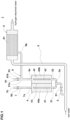
- Fig. 1 shows a schematic configuration of the hydrogen gas dissolution apparatus 1 in the present embodiment.
- the shaded area is an area filled with water (the same will apply to Fig. 3 below).
- the hydrogen gas dissolution apparatus 1 is equipped with an electrolysis tank 4 and a hydrogen gas dissolution module 6.
- the hydrogen gas dissolution module 6 dissolves the hydrogen gas supplied from the electrolysis tank 4 by bringing it into contact with water.
- an electrolysis chamber 40 is formed in the inside of the electrolysis tank 4.
- anode feed body 41 In the electrolysis chamber 40, there are disposed an anode feed body 41, a cathode feed body 42, and a diaphragm 43.
- the electrolysis chamber 40 is divided by the separating membrane 43 into an anode chamber 40a on the anode feed body 41 side, and a cathode chamber 40b on the cathode feed body 42 side.
- a solid polymeric material comprising a fluorinated resin having a sulfonic acid group or the like is appropriately used for the diaphragm 43.
- Water for electrolysis is supplied to the anode chamber 40a and the cathode chamber 40b.
- a water supply pipe 3 for supplying water for electrolysis to the anode chamber 40a and the cathode chamber 40b.
- the water supply pipe 3 branches into a water supply pipe 31 and a water supply pipe 32 at a bifurcation portion 3a.
- the water supply pipe 31 is connected to the anode chamber 40a, and the water supply pipe 32 is connected to the cathode chamber 40b.
- the water supply pipe 3 upstream of the bifurcation portion 3a is provided with an open/close valve 91 (first open/close valve).
- the hydrogen gas dissolution apparatus 1 is further provided with a water supply means for supplying water to the hydrogen gas dissolution module 6.
- the water supply means includes a water supply pipe 5.
- the water supply pipe 3 is branched from the water supply pipe 5. Accordingly, the water supply pipe 3 and the water supply pipe 5 are supplied with water from a water source of the same system. Thereby, the structure of the hydrogen gas dissolution apparatus 1 is simplified.
- water source of the water supply pipe 3 and the water source of the water supply pipe 5 are separate systems.
- the cathode chamber 40b and the hydrogen gas dissolution module 6 are connected by the undermentioned hydrogen extracting pipe 8.
- the hydrogen gas produced in the cathode chamber 40b is supplied to the hydrogen gas dissolution module 6 via the hydrogen extracting pipe 8.
- the hydrogen gas dissolution module 6 has a tube body 61 for passing water supplied from the water supply pipe 5.
- a plurality of tube bodies 61 are disposed inside the hydrogen gas dissolution module 6.
- the tube bodies 61 are extended in a horizontal direction.
- the tube body 61 is composed of a porous membrane which is hydrogen gas permeable. Thereby, the hydrogen gas supplied from the cathode chamber 40b permeates through the tube body 61, and comes into contact with and dissolves in the water in the tube body 61.
- a hollow fiber membrane is used as the porous membrane constituting the tube body 61.
- the hollow fiber membrane has innumerable micropores which allow hydrogen gas to permeate therethrough.
- the external pressure of the tube body 61 is increased by the hydrogen gas generated in the cathode chamber 40b, which causes the hydrogen gas existing outside the tube body 61 to move inward and dissolve in the water in the tube. Hydrogen dissolved water is easily obtained.
- Fig. 2 shows an electrical configuration of the hydrogen gas dissolution apparatus 1.
- the hydrogen gas dissolution apparatus 1 is equipped with a control means 10 which controls each of the anode feed body 41, the cathode feed body 42 and other parts.
- the control means 10 has, for example,
- a current supply line between the anode feed body 41 and the control means 10 is provided with a current sensing means 44.
- the current sensing means 44 may be provided in a current supply line between the cathode feed body 42 and the control means 10.
- the current sensing means 44 detects the electrolytic current supplied to the anode feed body 41 and the cathode feed body 42 and outputs an electrical signal corresponding to the value of the electrolytic current, to the control means 10.
- control means 10 controls, for example, a DC voltage applied to the anode feed body 41 and the cathode feed body 42.
- control means 10 controls the DC voltage applied to the anode feed body 41 and the cathode feed body 42 by feedback control so that the electrolysis current detected by the current sensing means 44 becomes a desired value according to a dissolved hydrogen concentration set by the user or the like.
- control means 10 decreases the above voltage. If the electrolytic current is excessively small, the control means 10 increases the above voltage. This allows the electrolytic current supplied to the anode feed body 41 and the cathode feed body 42 to be properly controlled.
- the hydrogen gas dissolution apparatus 1 in the present embodiment has the oxygen extracting pipe 7 for extracting oxygen gas from the anode chamber 40a of the electrolysis tank 4.
- the oxygen extracting pipe 7 has an inlet 7a on the side of the anode chamber 40a of the electrolysis tank 4, and an outlet 7b opened within the hydrogen gas dissolution apparatus 1.
- the inlet 7a is located above the anode chamber 40a of the electrolysis tank 4. Thereby, the hydrogen gas generated in the anode chamber 40a is facilitated to flow out into the oxygen extracting pipe 7 from the inlet 7a by the water pressure in the anode chamber 40a.
- the outlet 7b is provided at an end of the oxygen extracting pipe 7.
- the oxygen extracting pipe 7 may be arbitrarily extended so that the outlet 7b is opened outside the hydrogen gas dissolution apparatus 1.
- the hydrogen gas dissolution apparatus 1 is provided with the hydrogen extracting pipe 8 for extracting hydrogen gas from the electrolysis tank 4. It has an inlet 8a connected to the cathode chamber 40b of the electrolysis tank 4, and an outlet 8b connected to the hydrogen gas dissolution module 6.
- the hydrogen extracting pipe 8 supplies the hydrogen gas generated in the cathode chamber 40b to the hydrogen gas dissolution module 6.
- the inlet 8a is located at the upper part of the cathode chamber 40b of the electrolysis tank 4.
- outlet 8b is connected and opened to the lower part of the hydrogen gas dissolution module 6.
- the hydrogen extracting pipe 8 is connected to an opening pipe 81 whose end 81b is opened and which is branched from the hydrogen extracting pipe 8 at a bifurcation portion 81a.
- the opening pipe 81 is provided to open the cathode chamber 40b.
- the opening pipe 81 may be arbitrarily extended so that the end 81b is opened outside the hydrogen gas dissolution apparatus 1.
- An open/close valve 92 (second open/close valve) is provided near the outlet 7b of the oxygen extracting pipe 7 connected to the anode chamber 40a.
- An open/close valve 93 (second open/close valve) is provided near the end 81b of the opening pipe 81 branching from the hydrogen extracting pipe 8 connected to the cathode chamber 40b.
- the open/close valve 92 is provided to discharge the gas in the oxygen extracting pipe 7.
- the open/close valve 93 is provided to discharge the gas in the hydrogen extracting pipe 8.
- Fig. 3 shows a configuration of the electrolysis tank and its surroundings.
- anode chamber 40a and the cathode chamber 40b are maintained in a state of full water at any time in order that the electrolysis is performed efficiently in the electrolysis tank 4. Therefore, in the present embodiment, water is supplied from the water supply pipe 3 to the anode chamber 40a and the cathode chamber 40b prior to the electrolysis.
- the water level in the oxygen extracting pipe 7 becomes equal to the water level in the hydrogen extracting pipe 8.
- the open/close valves 91, 92 and 93 are, for example, composed of electromagnetic valves, and are controlled by the control means 10 to work in conjunction with each other.
- the control means 10 open the open/close valves 91, 92 and 93, the water pressure of the water supplied from the water supply pipe 31 discharges gas from the oxygen extracting pipe 7 and the hydrogen extracting pipe 8, and the water levels of the oxygen extracting pipe 7 and the hydrogen extracting pipe 8 are raised.
- the water levels of the oxygen extracting pipe 7 and the hydrogen extracting pipe 8, which are lowered by the electrolysis, can be raised in advance.
- control means 10 starts the electrolysis by applying a DC voltage for electrolysis to the anode feed body 41 and the cathode feed body 42 after closing of the open/close valves 91, 92, 93. That is, in a state where the open/close valves 91, 92, 93 are closed, the electrolysis is progressed in the electrolysis chamber 40, and hydrogen gas is generated in the cathode chamber 40b.
- the hydrogen gas in the hydrogen extracting pipe 8 is increased in the pressure, and pressurizes the tube body(bodies) 61 of the hydrogen gas dissolution module 6 from the outside. Accordingly, the hydrogen gas in contact with the water within the hydrogen gas dissolution module 6 is increased, which makes it possible to supply hydrogen dissolved water having a high dissolved hydrogen concentration at a low cost with a simple structure.
- the hydrogen gas dissolution apparatus 1 in the present embodiment is equipped with water level sensors (water level detection means) s1, s2, s3, s4 and s5 and the above-said open/close valves 91, 92 and 93
- the water level sensors s1 and s2 are arranged up and down at an appropriate interval on the oxygen extracting pipe 7.
- the water level sensor s5 is disposed between the water level sensor s1 and the water level sensor s2.
- the water level sensors s1, s2 and s5 detect the water in the pipe by an optical manner or buoyancy, and output to the control means 10 the corresponding electrical signals.
- control means 10 Based on the electrical signals input from the water level sensors s1, s2 and s5, the control means 10 knows and obtains the water level in the oxygen extracting pipe 7.
- the water level sensors s3 and s4 are arranged up and drawn at an appropriate interval on the hydrogen extracting pipe 8.
- the water level sensors s3 and s4 detect water in the pipe by an optical manner or buoyancy, and output to the control means 10 the corresponding electrical signals.
- control means 10 Based on the electrical signals input from the water level sensors s3 and s4, the control means 10 knows and obtains the water level in the hydrogen extracting pipe 8.
- the water level sensors s1 and s3 are located at the same height.
- the water level sensors s2 and s4 are located at the same height.
- the water level sensor s5 may be disposed on the hydrogen extracting pipe 8. In this case, the water level sensor s5 is located between the water level sensor s3 and the water level sensor s4.
- the water level sensor s4 is disposed below the bifurcation portion 81a. Thereby, when supplying water for electrolysis to the cathode chamber 40b, the water is prevented from entering into the hydrogen extracting pipe 8 on the hydrogen gas dissolution module 6 side than the bifurcation portion 81a.
- the control means 10 closes the open/close valves 91, 92, 93. This completes the replenishment of water into the electrolysis tank 4.
- the water level in the oxygen extracting pipe 7 and the water level in the hydrogen extracting pipe 8 are changed at different heights.
- control means 10 stops applying the electrolytic voltage to the anode feed body 41 and the cathode feed body 42.
- control means 10 stops the electrolysis when a drop in the water level in the oxygen extracting pipe 7 is detected by an electrical signal output from the water level sensor s1, or when a rise in the water level in the oxygen extracting pipe 7 is detected by an electrical signal output from the water level sensor s2.
- control means 10 stops the electrolysis when a drop in the water level in the hydrogen extracting pipe 8 is detected by the electrical signal output from the water level sensor s3, or when a rise in the water level in the hydrogen extracting pipe 8 is detected by the electrical signal output from the water level sensor s4.
- control means 10 opens the open/close valves 92 and 93.
- the pressure of the anode chamber 40a and the cathode chamber 40b becomes equal to the atmospheric pressure
- the water level in the oxygen extracting pipe 7 becomes equal to the water level in the hydrogen extracting pipe 8.
- the open/close valve 91 is opened and the water is replenished.
- the water level in the hydrogen extracting pipe 8 is maintained between the water level sensors s3 and s4.
- the control means 10 starts the electrolysis by applying a DC voltage for electrolysis to the anode feed body 41 and the cathode feed body 42 after closing the open/close valves 91, 92 and 93. That is, in such a state that the open/close valves 91, 92 and 93 have been closed, the electrolysis is progressed in the electrolysis chamber 40, and hydrogen gas is generated in the cathode chamber 40b. with this, the pressure in the hydrogen extracting pipe 8 increases and pressurizes the hydrogen gas dissolution module 6.
- the water level in the hydrogen extracting pipe 8 is kept lower than the outlet 8b by controlling the open/close valves 91, 92 and 93 by the control means 10.
- the hydrogen extracting pipe 8 may be provided with an open/close valve (not shown). This open/close valve is closed when the water for electrolysis is supplied to the cathode chamber 40b. This further prevents the water supplied from the water supply pipe 32 from flowing into the hydrogen gas dissolution module 6.
- the water supply pipe 3 is provided with a throttling valve 94 between the open/close valve 91 and the bifurcation portion 3a in order to limit the amount of water flowing through the water supply pipe 3.
- the throttling valve 94 inhibits the water supplied to the electrolysis chamber 40, from flowing out of the outlet 7b and the end 81b.
- the oxygen extracting pipe 7 is provided, between the open/close valve 92 and the outlet 7b, with a throttling valve 95 to limit the amount of water flowing through the oxygen extracting pipe 7.
- the opening pipe 81 is provided, between the open/close valve 93 and the end 81b, with a throttling valve 96 to limit the amount of water flowing through the opening pipe 81.
- the throttling valves 95 and 96 inhibit the water supplied to the electrolysis chamber 40 from flowing out of the outlet 7b and the end 81b.
- the throttling valves 95 and 96 may be omitted.
- the hydrogen gas dissolution apparatus 1 comprises the features of the independent claim 1.
Landscapes
- Chemical & Material Sciences (AREA)
- Chemical Kinetics & Catalysis (AREA)
- Engineering & Computer Science (AREA)
- Organic Chemistry (AREA)
- Electrochemistry (AREA)
- Metallurgy (AREA)
- Materials Engineering (AREA)
- Life Sciences & Earth Sciences (AREA)
- Water Supply & Treatment (AREA)
- Environmental & Geological Engineering (AREA)
- Hydrology & Water Resources (AREA)
- Analytical Chemistry (AREA)
- Automation & Control Theory (AREA)
- General Chemical & Material Sciences (AREA)
- Inorganic Chemistry (AREA)
- Health & Medical Sciences (AREA)
- Medicinal Chemistry (AREA)
- Electrolytic Production Of Non-Metals, Compounds, Apparatuses Therefor (AREA)
- Separation Using Semi-Permeable Membranes (AREA)
Claims (5)
- Wasserstoffgaslösevorrichtung (1), umfassend:einen Elektrolysetank (4) miteiner Anodenkammer (40a) zum Erzeugen von Sauerstoffgas durch Elektrolysieren von Wasser undeiner Kathodenkammer (40b) zum Erzeugen von Wasserstoffgas durch die Elektrolyse,ein Wasserstoffextraktionsrohr (8), das mit der Kathodenkammer (40b) verbunden ist, zum Extrahieren des Wasserstoffgases aus der Kathodenkammer (40b),ein Sauerstoffextraktionsrohr (7), das mit der Anodenkammer (40a) verbunden ist, zum Extrahieren des Sauerstoffgases aus der Anodenkammer (40a),ein erstes Wasserzufuhrrohr (3) zum Zuführen des Wassers zur Elektrolyse zu der Anodenkammer (40a) und der Kathodenkammer (40b), wobei das erste Wasserzufuhrrohr (3) sich in ein zweites Wasserzufuhrrohr (31) und ein drittes Wasserzufuhrrohr (32) an einem ersten Gabelungsabschnitt (3a) verzweigt,das zweite Wasserzufuhrrohr (31) mit der Anodenkammer (40a) verbunden ist, unddas dritte Wasserzufuhrrohr (32) mit der Kathodenkammer (40b) verbunden ist,ein Öffnungsrohr (81) zum Öffnen der Kathodenkammer (40b), wobei das Öffnungsrohr (81) indirekt mit der Kathodenkammer (40b) durch das Wasserstoffextraktionsrohr (8) verbunden ist, indem es von dem Wasserstoffextraktionsrohr (8) an einem zweiten Gabelungsabschnitt (81a) verzweigt ist,ein viertes Wasserzufuhrrohr (5) zum Zuführen von Wasser zu einem Wasserstoffgaslösungsmodul (6), das mit dem Wasserstoffextraktionsrohr (8) verbunden ist und konfiguriert ist, um das von dem Wasserstoffextraktionsrohr (8) zugeführte Wasserstoffgas aufzulösen, indem es dieses mit dem von dem vierten Wasserzufuhrrohr (5) zugeführten Wasser in Kontakt bringt,ein erstes Öffnungs-/Schließventil (91), das an dem ersten Wasserzufuhrrohr (3) an einer Position auf der stromaufwärtigen Seite des ersten Gabelungsabschnitts (3a) angebracht ist,ein zweites Öffnungs-/Schließventil (92, 93), das in jedem von dem Sauerstoffextraktionsrohr (7) und dem Öffnungsrohr (81) bereitgestellt ist, und ein Steuermittel (10) zum Steuern des Elektrolysetanks (4), des ersten Öffnungs-/Schließventils (91) und der zweiten Öffnungs-/Schließventile (92, 93),wobeidas Steuermittel (10) konfiguriert ist, um:das zweite Öffnungs-/Schließventil (92) des Sauerstoffextraktionsrohrs (7) und das zweite Öffnungs-/Schließventil (93) des Öffnungsrohrs (81) zu öffnen, um Gas aus dem Sauerstoffextraktionsrohr (7) und dem Wasserstoffextraktionsrohr (8) abzuführen,und das erste Öffnungs-/Schließventil (91) zu öffnen, um das Wasser der Anodenkammer (40a) und der Kathodenkammer (40b) über das zweite Wasserzufuhrrohr (31) bzw. das dritte Wasserzufuhrrohr (32) zuzuführen, und dann das erste Öffnungs-/Schließventil (91), das zweite Öffnungs-/Schließventil (92) und das zweite Öffnungs-/Schließventil (93) zu schlie-ßen, nachdem die Wasserpegel des Sauerstoffextraktionsrohrs (7) und des Wasserstoffextraktionsrohrs (8) infolge des der Anodenkammer (40a) und der Kathodenkammer (40b) zugeführten Wassers erhöht sind,und dann die Elektrolyse startet.
- Wasserstoffgaslösevorrichtung (1) nach Anspruch 1, wobeidas Wasserstoffextraktionsrohr (8) und/oder das Sauerstoffextraktionsrohr (7) mit einem ersten Wasserpegelerfassungsmittel zum Erfassen des Wasserpegels in dem Rohr (7, 8) versehen ist,das Steuermittel (10) konfiguriert ist, um:
das erste Öffnungs-/Schließventil (91) und die zwei zweiten Öffnungs-/Schließventile (92, 93) zu schließen, wenn ein Anstieg des Wasserpegels in dem Rohr durch das erste Wasserpegelerfassungsmittel erfasst wird, und die Elektrolyse zu starten. - Wasserstoffgaslösevorrichtung (1) nach einem der Ansprüche 1 oder 2, wobei sich das erste Wasserzufuhrrohr (3) von dem vierten Wasserzufuhrrohr (5) verzweigt, wodurch das erste Wasserzufuhrrohr (3) und das vierte Wasserzufuhrrohr (5) mit dem Wasser von einer gleichen Wasserquelle versorgt werden.
- Wasserstoffgaslösevorrichtung (1) nach Anspruch 3, wobeidas Wasserstoffgas-Lösungsmodul (6) einen Rohrkörper (61) zum Leiten des von dem vierten Wasserzufuhrrohr (5) zugeführten Wassers aufweist, undder Rohrkörper (61) aus einer porösen Membran besteht, die einen Durchgang des Wasserstoffgases zulässt.
- Wasserstoffgaslösevorrichtung (1) nach Anspruch 4, wobei
die poröse Membran eine Hohlfasermembran ist.
Applications Claiming Priority (2)
| Application Number | Priority Date | Filing Date | Title |
|---|---|---|---|
| JP2018108795A JP6767431B2 (ja) | 2018-06-06 | 2018-06-06 | 水素ガス溶解装置 |
| PCT/JP2019/022158 WO2019235473A1 (ja) | 2018-06-06 | 2019-06-04 | 水素ガス溶解装置 |
Publications (3)
| Publication Number | Publication Date |
|---|---|
| EP3766568A1 EP3766568A1 (de) | 2021-01-20 |
| EP3766568A4 EP3766568A4 (de) | 2021-12-22 |
| EP3766568B1 true EP3766568B1 (de) | 2024-07-31 |
Family
ID=68770847
Family Applications (1)
| Application Number | Title | Priority Date | Filing Date |
|---|---|---|---|
| EP19815555.8A Active EP3766568B1 (de) | 2018-06-06 | 2019-06-04 | Vorrichtung zum lösen von wasserstoffgas |
Country Status (5)
| Country | Link |
|---|---|
| US (1) | US11788197B2 (de) |
| EP (1) | EP3766568B1 (de) |
| JP (1) | JP6767431B2 (de) |
| CN (1) | CN112203751A (de) |
| WO (1) | WO2019235473A1 (de) |
Families Citing this family (4)
| Publication number | Priority date | Publication date | Assignee | Title |
|---|---|---|---|---|
| JP7041731B1 (ja) | 2020-11-30 | 2022-03-24 | 株式会社日本トリム | 電解水生成装置 |
| JP7284845B2 (ja) * | 2020-11-30 | 2023-05-31 | 株式会社日本トリム | 電解水生成装置 |
| US11291183B1 (en) | 2021-08-13 | 2022-04-05 | Green Life Llc | Pet hydration system |
| DE102023207462A1 (de) | 2023-08-03 | 2025-02-06 | Robert Bosch Gesellschaft mit beschränkter Haftung | Diagnoseverfahren, Überwachungssystem und Energiewandler |
Family Cites Families (14)
| Publication number | Priority date | Publication date | Assignee | Title |
|---|---|---|---|---|
| JP3220607B2 (ja) | 1995-01-18 | 2001-10-22 | 三菱商事株式会社 | 水素・酸素ガス発生装置 |
| JP3296405B2 (ja) * | 1996-08-20 | 2002-07-02 | オルガノ株式会社 | 電子部品部材類の洗浄方法及び洗浄装置 |
| CN1299333C (zh) * | 1996-08-20 | 2007-02-07 | 奥加诺株式会社 | 清洗电子元件或其制造设备的元件的方法和装置 |
| JP3732330B2 (ja) * | 1998-02-27 | 2006-01-05 | オルガノ株式会社 | ガス溶解水製造装置 |
| JP2000008083A (ja) * | 1998-06-18 | 2000-01-11 | Japan Organo Co Ltd | ガス溶解水製造装置 |
| JP3768027B2 (ja) * | 1999-04-12 | 2006-04-19 | オルガノ株式会社 | ガス溶解水製造装置 |
| ATE504674T1 (de) * | 2003-02-21 | 2011-04-15 | Avalence Llc | Elektrolyseapparatur und verfahren zur herstellung von wasserstoff |
| JP4573904B1 (ja) * | 2009-05-27 | 2010-11-04 | 株式会社バイオリサーチ | 飲料用水素含有水の製造方法 |
| JP5552792B2 (ja) * | 2009-10-19 | 2014-07-16 | 栗田工業株式会社 | ガス溶解水製造装置及び製造方法 |
| JP6185445B2 (ja) | 2014-10-20 | 2017-08-23 | 株式会社ドクターズ・マン | 水素水供給装置 |
| CN106148989A (zh) * | 2015-03-30 | 2016-11-23 | 黄飞灵 | 一种电能存储系统及产生氢气和氧气的方法 |
| JP6069412B2 (ja) * | 2015-05-28 | 2017-02-01 | 株式会社TrアンドK | 簡易型の電解式水素ガス発生装置 |
| JP6219358B2 (ja) * | 2015-11-05 | 2017-10-25 | 株式会社日本トリム | 水素水サーバー |
| JP6148759B1 (ja) * | 2016-05-11 | 2017-06-14 | MiZ株式会社 | 水素含有液体の水素濃度を求める方法及び水素含有液体の生成装置 |
-
2018
- 2018-06-06 JP JP2018108795A patent/JP6767431B2/ja active Active
-
2019
- 2019-06-04 WO PCT/JP2019/022158 patent/WO2019235473A1/ja not_active Ceased
- 2019-06-04 US US17/049,437 patent/US11788197B2/en active Active
- 2019-06-04 CN CN201980035439.9A patent/CN112203751A/zh active Pending
- 2019-06-04 EP EP19815555.8A patent/EP3766568B1/de active Active
Also Published As
| Publication number | Publication date |
|---|---|
| CN112203751A (zh) | 2021-01-08 |
| JP2019209284A (ja) | 2019-12-12 |
| US20210079545A1 (en) | 2021-03-18 |
| WO2019235473A1 (ja) | 2019-12-12 |
| EP3766568A1 (de) | 2021-01-20 |
| JP6767431B2 (ja) | 2020-10-14 |
| US11788197B2 (en) | 2023-10-17 |
| EP3766568A4 (de) | 2021-12-22 |
Similar Documents
| Publication | Publication Date | Title |
|---|---|---|
| EP3766568B1 (de) | Vorrichtung zum lösen von wasserstoffgas | |
| CN113412146B (zh) | 加氢装置以及氢透过膜的消耗度判定方法 | |
| JP7514366B2 (ja) | 水素ガス溶解装置 | |
| JP2016077987A (ja) | 水素水供給装置 | |
| JP7245002B2 (ja) | 水素ガス溶解装置 | |
| EP3797859B1 (de) | Vorrichtung zur auflösung von wasserstoffgas | |
| EP3578519B1 (de) | Vorrichtung zur erzeugung von elektrolysiertem wasser | |
| JP7373023B1 (ja) | 電解水生成装置及び水処理装置 | |
| CN113396009B (zh) | 加氢装置以及氢透过膜的消耗度判定方法 | |
| CN113396008A (zh) | 加氢装置以及加氢方法 | |
| JP5811551B2 (ja) | 純水製造装置 | |
| JP6506730B2 (ja) | 電解水サーバー | |
| JP2005279519A (ja) | 電解水生成装置 | |
| HK40054151A (en) | Hydrogen supplementation device and hydrogen supplementation method | |
| KR101744866B1 (ko) | 수소수공급장치 | |
| HK40054151B (zh) | 加氢装置以及加氢方法 |
Legal Events
| Date | Code | Title | Description |
|---|---|---|---|
| STAA | Information on the status of an ep patent application or granted ep patent |
Free format text: STATUS: THE INTERNATIONAL PUBLICATION HAS BEEN MADE |
|
| PUAI | Public reference made under article 153(3) epc to a published international application that has entered the european phase |
Free format text: ORIGINAL CODE: 0009012 |
|
| STAA | Information on the status of an ep patent application or granted ep patent |
Free format text: STATUS: REQUEST FOR EXAMINATION WAS MADE |
|
| 17P | Request for examination filed |
Effective date: 20201015 |
|
| AK | Designated contracting states |
Kind code of ref document: A1 Designated state(s): AL AT BE BG CH CY CZ DE DK EE ES FI FR GB GR HR HU IE IS IT LI LT LU LV MC MK MT NL NO PL PT RO RS SE SI SK SM TR |
|
| AX | Request for extension of the european patent |
Extension state: BA ME |
|
| DAV | Request for validation of the european patent (deleted) | ||
| DAX | Request for extension of the european patent (deleted) | ||
| A4 | Supplementary search report drawn up and despatched |
Effective date: 20211122 |
|
| RIC1 | Information provided on ipc code assigned before grant |
Ipc: B01F 3/04 20060101ALI20211116BHEP Ipc: B01D 69/02 20060101ALI20211116BHEP Ipc: C02F 1/461 20060101ALI20211116BHEP Ipc: C25B 15/08 20060101ALI20211116BHEP Ipc: C25B 15/023 20210101ALI20211116BHEP Ipc: C25B 15/02 20210101ALI20211116BHEP Ipc: C25B 9/19 20210101ALI20211116BHEP Ipc: C25B 1/04 20210101AFI20211116BHEP |
|
| REG | Reference to a national code |
Ref country code: DE Ref legal event code: R079 Free format text: PREVIOUS MAIN CLASS: B01F0001000000 Ipc: C25B0001040000 Ref country code: DE Ref legal event code: R079 Ref document number: 602019056215 Country of ref document: DE Free format text: PREVIOUS MAIN CLASS: B01F0001000000 Ipc: C25B0001040000 |
|
| GRAP | Despatch of communication of intention to grant a patent |
Free format text: ORIGINAL CODE: EPIDOSNIGR1 |
|
| STAA | Information on the status of an ep patent application or granted ep patent |
Free format text: STATUS: GRANT OF PATENT IS INTENDED |
|
| RIC1 | Information provided on ipc code assigned before grant |
Ipc: B01F 25/314 20220101ALI20240214BHEP Ipc: B01F 23/237 20220101ALI20240214BHEP Ipc: B01F 23/232 20220101ALI20240214BHEP Ipc: B01F 23/231 20220101ALI20240214BHEP Ipc: B01D 69/02 20060101ALI20240214BHEP Ipc: C02F 1/461 20060101ALI20240214BHEP Ipc: C25B 15/08 20060101ALI20240214BHEP Ipc: C25B 15/023 20210101ALI20240214BHEP Ipc: C25B 15/02 20210101ALI20240214BHEP Ipc: C25B 9/19 20210101ALI20240214BHEP Ipc: C25B 1/04 20210101AFI20240214BHEP |
|
| INTG | Intention to grant announced |
Effective date: 20240229 |
|
| GRAS | Grant fee paid |
Free format text: ORIGINAL CODE: EPIDOSNIGR3 |
|
| GRAA | (expected) grant |
Free format text: ORIGINAL CODE: 0009210 |
|
| STAA | Information on the status of an ep patent application or granted ep patent |
Free format text: STATUS: THE PATENT HAS BEEN GRANTED |
|
| AK | Designated contracting states |
Kind code of ref document: B1 Designated state(s): AL AT BE BG CH CY CZ DE DK EE ES FI FR GB GR HR HU IE IS IT LI LT LU LV MC MK MT NL NO PL PT RO RS SE SI SK SM TR |
|
| REG | Reference to a national code |
Ref country code: CH Ref legal event code: EP Ref country code: GB Ref legal event code: FG4D |
|
| REG | Reference to a national code |
Ref country code: DE Ref legal event code: R096 Ref document number: 602019056215 Country of ref document: DE |
|
| REG | Reference to a national code |
Ref country code: IE Ref legal event code: FG4D |
|
| REG | Reference to a national code |
Ref country code: LT Ref legal event code: MG9D |
|
| REG | Reference to a national code |
Ref country code: NL Ref legal event code: MP Effective date: 20240731 |
|
| PG25 | Lapsed in a contracting state [announced via postgrant information from national office to epo] |
Ref country code: PT Free format text: LAPSE BECAUSE OF FAILURE TO SUBMIT A TRANSLATION OF THE DESCRIPTION OR TO PAY THE FEE WITHIN THE PRESCRIBED TIME-LIMIT Effective date: 20241202 |
|
| REG | Reference to a national code |
Ref country code: AT Ref legal event code: MK05 Ref document number: 1708529 Country of ref document: AT Kind code of ref document: T Effective date: 20240731 |
|
| PG25 | Lapsed in a contracting state [announced via postgrant information from national office to epo] |
Ref country code: PT Free format text: LAPSE BECAUSE OF FAILURE TO SUBMIT A TRANSLATION OF THE DESCRIPTION OR TO PAY THE FEE WITHIN THE PRESCRIBED TIME-LIMIT Effective date: 20241202 |
|
| PG25 | Lapsed in a contracting state [announced via postgrant information from national office to epo] |
Ref country code: NO Free format text: LAPSE BECAUSE OF FAILURE TO SUBMIT A TRANSLATION OF THE DESCRIPTION OR TO PAY THE FEE WITHIN THE PRESCRIBED TIME-LIMIT Effective date: 20241031 |
|
| PG25 | Lapsed in a contracting state [announced via postgrant information from national office to epo] |
Ref country code: FI Free format text: LAPSE BECAUSE OF FAILURE TO SUBMIT A TRANSLATION OF THE DESCRIPTION OR TO PAY THE FEE WITHIN THE PRESCRIBED TIME-LIMIT Effective date: 20240731 Ref country code: NL Free format text: LAPSE BECAUSE OF FAILURE TO SUBMIT A TRANSLATION OF THE DESCRIPTION OR TO PAY THE FEE WITHIN THE PRESCRIBED TIME-LIMIT Effective date: 20240731 Ref country code: PL Free format text: LAPSE BECAUSE OF FAILURE TO SUBMIT A TRANSLATION OF THE DESCRIPTION OR TO PAY THE FEE WITHIN THE PRESCRIBED TIME-LIMIT Effective date: 20240731 Ref country code: GR Free format text: LAPSE BECAUSE OF FAILURE TO SUBMIT A TRANSLATION OF THE DESCRIPTION OR TO PAY THE FEE WITHIN THE PRESCRIBED TIME-LIMIT Effective date: 20241101 |
|
| PG25 | Lapsed in a contracting state [announced via postgrant information from national office to epo] |
Ref country code: BG Free format text: LAPSE BECAUSE OF FAILURE TO SUBMIT A TRANSLATION OF THE DESCRIPTION OR TO PAY THE FEE WITHIN THE PRESCRIBED TIME-LIMIT Effective date: 20240731 |
|
| PG25 | Lapsed in a contracting state [announced via postgrant information from national office to epo] |
Ref country code: LV Free format text: LAPSE BECAUSE OF FAILURE TO SUBMIT A TRANSLATION OF THE DESCRIPTION OR TO PAY THE FEE WITHIN THE PRESCRIBED TIME-LIMIT Effective date: 20240731 |
|
| PG25 | Lapsed in a contracting state [announced via postgrant information from national office to epo] |
Ref country code: AT Free format text: LAPSE BECAUSE OF FAILURE TO SUBMIT A TRANSLATION OF THE DESCRIPTION OR TO PAY THE FEE WITHIN THE PRESCRIBED TIME-LIMIT Effective date: 20240731 Ref country code: IS Free format text: LAPSE BECAUSE OF FAILURE TO SUBMIT A TRANSLATION OF THE DESCRIPTION OR TO PAY THE FEE WITHIN THE PRESCRIBED TIME-LIMIT Effective date: 20241130 |
|
| PG25 | Lapsed in a contracting state [announced via postgrant information from national office to epo] |
Ref country code: HR Free format text: LAPSE BECAUSE OF FAILURE TO SUBMIT A TRANSLATION OF THE DESCRIPTION OR TO PAY THE FEE WITHIN THE PRESCRIBED TIME-LIMIT Effective date: 20240731 |
|
| PG25 | Lapsed in a contracting state [announced via postgrant information from national office to epo] |
Ref country code: RS Free format text: LAPSE BECAUSE OF FAILURE TO SUBMIT A TRANSLATION OF THE DESCRIPTION OR TO PAY THE FEE WITHIN THE PRESCRIBED TIME-LIMIT Effective date: 20241031 Ref country code: ES Free format text: LAPSE BECAUSE OF FAILURE TO SUBMIT A TRANSLATION OF THE DESCRIPTION OR TO PAY THE FEE WITHIN THE PRESCRIBED TIME-LIMIT Effective date: 20240731 |
|
| PG25 | Lapsed in a contracting state [announced via postgrant information from national office to epo] |
Ref country code: RS Free format text: LAPSE BECAUSE OF FAILURE TO SUBMIT A TRANSLATION OF THE DESCRIPTION OR TO PAY THE FEE WITHIN THE PRESCRIBED TIME-LIMIT Effective date: 20241031 Ref country code: PL Free format text: LAPSE BECAUSE OF FAILURE TO SUBMIT A TRANSLATION OF THE DESCRIPTION OR TO PAY THE FEE WITHIN THE PRESCRIBED TIME-LIMIT Effective date: 20240731 Ref country code: NO Free format text: LAPSE BECAUSE OF FAILURE TO SUBMIT A TRANSLATION OF THE DESCRIPTION OR TO PAY THE FEE WITHIN THE PRESCRIBED TIME-LIMIT Effective date: 20241031 Ref country code: NL Free format text: LAPSE BECAUSE OF FAILURE TO SUBMIT A TRANSLATION OF THE DESCRIPTION OR TO PAY THE FEE WITHIN THE PRESCRIBED TIME-LIMIT Effective date: 20240731 Ref country code: LV Free format text: LAPSE BECAUSE OF FAILURE TO SUBMIT A TRANSLATION OF THE DESCRIPTION OR TO PAY THE FEE WITHIN THE PRESCRIBED TIME-LIMIT Effective date: 20240731 Ref country code: IS Free format text: LAPSE BECAUSE OF FAILURE TO SUBMIT A TRANSLATION OF THE DESCRIPTION OR TO PAY THE FEE WITHIN THE PRESCRIBED TIME-LIMIT Effective date: 20241130 Ref country code: HR Free format text: LAPSE BECAUSE OF FAILURE TO SUBMIT A TRANSLATION OF THE DESCRIPTION OR TO PAY THE FEE WITHIN THE PRESCRIBED TIME-LIMIT Effective date: 20240731 Ref country code: GR Free format text: LAPSE BECAUSE OF FAILURE TO SUBMIT A TRANSLATION OF THE DESCRIPTION OR TO PAY THE FEE WITHIN THE PRESCRIBED TIME-LIMIT Effective date: 20241101 Ref country code: FI Free format text: LAPSE BECAUSE OF FAILURE TO SUBMIT A TRANSLATION OF THE DESCRIPTION OR TO PAY THE FEE WITHIN THE PRESCRIBED TIME-LIMIT Effective date: 20240731 Ref country code: ES Free format text: LAPSE BECAUSE OF FAILURE TO SUBMIT A TRANSLATION OF THE DESCRIPTION OR TO PAY THE FEE WITHIN THE PRESCRIBED TIME-LIMIT Effective date: 20240731 Ref country code: BG Free format text: LAPSE BECAUSE OF FAILURE TO SUBMIT A TRANSLATION OF THE DESCRIPTION OR TO PAY THE FEE WITHIN THE PRESCRIBED TIME-LIMIT Effective date: 20240731 Ref country code: AT Free format text: LAPSE BECAUSE OF FAILURE TO SUBMIT A TRANSLATION OF THE DESCRIPTION OR TO PAY THE FEE WITHIN THE PRESCRIBED TIME-LIMIT Effective date: 20240731 |
|
| PG25 | Lapsed in a contracting state [announced via postgrant information from national office to epo] |
Ref country code: SM Free format text: LAPSE BECAUSE OF FAILURE TO SUBMIT A TRANSLATION OF THE DESCRIPTION OR TO PAY THE FEE WITHIN THE PRESCRIBED TIME-LIMIT Effective date: 20240731 Ref country code: DK Free format text: LAPSE BECAUSE OF FAILURE TO SUBMIT A TRANSLATION OF THE DESCRIPTION OR TO PAY THE FEE WITHIN THE PRESCRIBED TIME-LIMIT Effective date: 20240731 Ref country code: RO Free format text: LAPSE BECAUSE OF FAILURE TO SUBMIT A TRANSLATION OF THE DESCRIPTION OR TO PAY THE FEE WITHIN THE PRESCRIBED TIME-LIMIT Effective date: 20240731 |
|
| PG25 | Lapsed in a contracting state [announced via postgrant information from national office to epo] |
Ref country code: EE Free format text: LAPSE BECAUSE OF FAILURE TO SUBMIT A TRANSLATION OF THE DESCRIPTION OR TO PAY THE FEE WITHIN THE PRESCRIBED TIME-LIMIT Effective date: 20240731 |
|
| PG25 | Lapsed in a contracting state [announced via postgrant information from national office to epo] |
Ref country code: CZ Free format text: LAPSE BECAUSE OF FAILURE TO SUBMIT A TRANSLATION OF THE DESCRIPTION OR TO PAY THE FEE WITHIN THE PRESCRIBED TIME-LIMIT Effective date: 20240731 |
|
| PG25 | Lapsed in a contracting state [announced via postgrant information from national office to epo] |
Ref country code: SK Free format text: LAPSE BECAUSE OF FAILURE TO SUBMIT A TRANSLATION OF THE DESCRIPTION OR TO PAY THE FEE WITHIN THE PRESCRIBED TIME-LIMIT Effective date: 20240731 Ref country code: IT Free format text: LAPSE BECAUSE OF FAILURE TO SUBMIT A TRANSLATION OF THE DESCRIPTION OR TO PAY THE FEE WITHIN THE PRESCRIBED TIME-LIMIT Effective date: 20240731 |
|
| REG | Reference to a national code |
Ref country code: DE Ref legal event code: R097 Ref document number: 602019056215 Country of ref document: DE |
|
| PLBE | No opposition filed within time limit |
Free format text: ORIGINAL CODE: 0009261 |
|
| STAA | Information on the status of an ep patent application or granted ep patent |
Free format text: STATUS: NO OPPOSITION FILED WITHIN TIME LIMIT |
|
| 26N | No opposition filed |
Effective date: 20250501 |
|
| PGFP | Annual fee paid to national office [announced via postgrant information from national office to epo] |
Ref country code: GB Payment date: 20250618 Year of fee payment: 7 |
|
| PGFP | Annual fee paid to national office [announced via postgrant information from national office to epo] |
Ref country code: FR Payment date: 20250626 Year of fee payment: 7 |
|
| PG25 | Lapsed in a contracting state [announced via postgrant information from national office to epo] |
Ref country code: SE Free format text: LAPSE BECAUSE OF FAILURE TO SUBMIT A TRANSLATION OF THE DESCRIPTION OR TO PAY THE FEE WITHIN THE PRESCRIBED TIME-LIMIT Effective date: 20240731 |
|
| PGFP | Annual fee paid to national office [announced via postgrant information from national office to epo] |
Ref country code: DE Payment date: 20250827 Year of fee payment: 7 |
|
| REG | Reference to a national code |
Ref country code: CH Ref legal event code: H13 Free format text: ST27 STATUS EVENT CODE: U-0-0-H10-H13 (AS PROVIDED BY THE NATIONAL OFFICE) Effective date: 20260127 |
|
| PG25 | Lapsed in a contracting state [announced via postgrant information from national office to epo] |
Ref country code: MC Free format text: LAPSE BECAUSE OF FAILURE TO SUBMIT A TRANSLATION OF THE DESCRIPTION OR TO PAY THE FEE WITHIN THE PRESCRIBED TIME-LIMIT Effective date: 20240731 |
|
| PG25 | Lapsed in a contracting state [announced via postgrant information from national office to epo] |
Ref country code: LU Free format text: LAPSE BECAUSE OF NON-PAYMENT OF DUE FEES Effective date: 20250604 |
|
| REG | Reference to a national code |
Ref country code: BE Ref legal event code: MM Effective date: 20250630 |
|
| PG25 | Lapsed in a contracting state [announced via postgrant information from national office to epo] |
Ref country code: IE Free format text: LAPSE BECAUSE OF NON-PAYMENT OF DUE FEES Effective date: 20250604 |
|
| PG25 | Lapsed in a contracting state [announced via postgrant information from national office to epo] |
Ref country code: BE Free format text: LAPSE BECAUSE OF NON-PAYMENT OF DUE FEES Effective date: 20250630 |
|
| PG25 | Lapsed in a contracting state [announced via postgrant information from national office to epo] |
Ref country code: CH Free format text: LAPSE BECAUSE OF NON-PAYMENT OF DUE FEES Effective date: 20250630 |