EP3766611A2 - Verfahren und vorrichtung zur herstellung von schwermetallpulvern durch ultraschallzerstäubung - Google Patents
Verfahren und vorrichtung zur herstellung von schwermetallpulvern durch ultraschallzerstäubung Download PDFInfo
- Publication number
- EP3766611A2 EP3766611A2 EP20179851.9A EP20179851A EP3766611A2 EP 3766611 A2 EP3766611 A2 EP 3766611A2 EP 20179851 A EP20179851 A EP 20179851A EP 3766611 A2 EP3766611 A2 EP 3766611A2
- Authority
- EP
- European Patent Office
- Prior art keywords
- heavy metal
- raw material
- electric arc
- sonotrode
- droplets
- Prior art date
- Legal status (The legal status is an assumption and is not a legal conclusion. Google has not performed a legal analysis and makes no representation as to the accuracy of the status listed.)
- Pending
Links
Images




Classifications
-
- B—PERFORMING OPERATIONS; TRANSPORTING
- B22—CASTING; POWDER METALLURGY
- B22F—WORKING METALLIC POWDER; MANUFACTURE OF ARTICLES FROM METALLIC POWDER; MAKING METALLIC POWDER; APPARATUS OR DEVICES SPECIALLY ADAPTED FOR METALLIC POWDER
- B22F9/00—Making metallic powder or suspensions thereof
- B22F9/02—Making metallic powder or suspensions thereof using physical processes
- B22F9/06—Making metallic powder or suspensions thereof using physical processes starting from liquid material
- B22F9/08—Making metallic powder or suspensions thereof using physical processes starting from liquid material by casting, e.g. through sieves or in water, by atomising or spraying
-
- B—PERFORMING OPERATIONS; TRANSPORTING
- B22—CASTING; POWDER METALLURGY
- B22F—WORKING METALLIC POWDER; MANUFACTURE OF ARTICLES FROM METALLIC POWDER; MAKING METALLIC POWDER; APPARATUS OR DEVICES SPECIALLY ADAPTED FOR METALLIC POWDER
- B22F1/00—Metallic powder; Treatment of metallic powder, e.g. to facilitate working or to improve properties
- B22F1/05—Metallic powder characterised by the size or surface area of the particles
- B22F1/052—Metallic powder characterised by the size or surface area of the particles characterised by a mixture of particles of different sizes or by the particle size distribution
-
- B—PERFORMING OPERATIONS; TRANSPORTING
- B22—CASTING; POWDER METALLURGY
- B22F—WORKING METALLIC POWDER; MANUFACTURE OF ARTICLES FROM METALLIC POWDER; MAKING METALLIC POWDER; APPARATUS OR DEVICES SPECIALLY ADAPTED FOR METALLIC POWDER
- B22F1/00—Metallic powder; Treatment of metallic powder, e.g. to facilitate working or to improve properties
- B22F1/06—Metallic powder characterised by the shape of the particles
- B22F1/065—Spherical particles
-
- B—PERFORMING OPERATIONS; TRANSPORTING
- B22—CASTING; POWDER METALLURGY
- B22F—WORKING METALLIC POWDER; MANUFACTURE OF ARTICLES FROM METALLIC POWDER; MAKING METALLIC POWDER; APPARATUS OR DEVICES SPECIALLY ADAPTED FOR METALLIC POWDER
- B22F10/00—Additive manufacturing of workpieces or articles from metallic powder
- B22F10/30—Process control
- B22F10/32—Process control of the atmosphere, e.g. composition or pressure in a building chamber
-
- B—PERFORMING OPERATIONS; TRANSPORTING
- B22—CASTING; POWDER METALLURGY
- B22F—WORKING METALLIC POWDER; MANUFACTURE OF ARTICLES FROM METALLIC POWDER; MAKING METALLIC POWDER; APPARATUS OR DEVICES SPECIALLY ADAPTED FOR METALLIC POWDER
- B22F10/00—Additive manufacturing of workpieces or articles from metallic powder
- B22F10/30—Process control
- B22F10/32—Process control of the atmosphere, e.g. composition or pressure in a building chamber
- B22F10/322—Process control of the atmosphere, e.g. composition or pressure in a building chamber of the gas flow, e.g. rate or direction
-
- B—PERFORMING OPERATIONS; TRANSPORTING
- B22—CASTING; POWDER METALLURGY
- B22F—WORKING METALLIC POWDER; MANUFACTURE OF ARTICLES FROM METALLIC POWDER; MAKING METALLIC POWDER; APPARATUS OR DEVICES SPECIALLY ADAPTED FOR METALLIC POWDER
- B22F10/00—Additive manufacturing of workpieces or articles from metallic powder
- B22F10/30—Process control
- B22F10/36—Process control of energy beam parameters
- B22F10/368—Temperature or temperature gradient, e.g. temperature of the melt pool
-
- B—PERFORMING OPERATIONS; TRANSPORTING
- B22—CASTING; POWDER METALLURGY
- B22F—WORKING METALLIC POWDER; MANUFACTURE OF ARTICLES FROM METALLIC POWDER; MAKING METALLIC POWDER; APPARATUS OR DEVICES SPECIALLY ADAPTED FOR METALLIC POWDER
- B22F12/00—Apparatus or devices specially adapted for additive manufacturing; Auxiliary means for additive manufacturing; Combinations of additive manufacturing apparatus or devices with other processing apparatus or devices
- B22F12/10—Auxiliary heating means
- B22F12/13—Auxiliary heating means to preheat the material
-
- B—PERFORMING OPERATIONS; TRANSPORTING
- B22—CASTING; POWDER METALLURGY
- B22F—WORKING METALLIC POWDER; MANUFACTURE OF ARTICLES FROM METALLIC POWDER; MAKING METALLIC POWDER; APPARATUS OR DEVICES SPECIALLY ADAPTED FOR METALLIC POWDER
- B22F12/00—Apparatus or devices specially adapted for additive manufacturing; Auxiliary means for additive manufacturing; Combinations of additive manufacturing apparatus or devices with other processing apparatus or devices
- B22F12/40—Radiation means
- B22F12/41—Radiation means characterised by the type, e.g. laser or electron beam
-
- B—PERFORMING OPERATIONS; TRANSPORTING
- B22—CASTING; POWDER METALLURGY
- B22F—WORKING METALLIC POWDER; MANUFACTURE OF ARTICLES FROM METALLIC POWDER; MAKING METALLIC POWDER; APPARATUS OR DEVICES SPECIALLY ADAPTED FOR METALLIC POWDER
- B22F9/00—Making metallic powder or suspensions thereof
- B22F9/02—Making metallic powder or suspensions thereof using physical processes
- B22F9/06—Making metallic powder or suspensions thereof using physical processes starting from liquid material
- B22F9/08—Making metallic powder or suspensions thereof using physical processes starting from liquid material by casting, e.g. through sieves or in water, by atomising or spraying
- B22F9/082—Making metallic powder or suspensions thereof using physical processes starting from liquid material by casting, e.g. through sieves or in water, by atomising or spraying atomising using a fluid
-
- B—PERFORMING OPERATIONS; TRANSPORTING
- B33—ADDITIVE MANUFACTURING TECHNOLOGY
- B33Y—ADDITIVE MANUFACTURING, i.e. MANUFACTURING OF THREE-DIMENSIONAL [3D] OBJECTS BY ADDITIVE DEPOSITION, ADDITIVE AGGLOMERATION OR ADDITIVE LAYERING, e.g. BY 3D PRINTING, STEREOLITHOGRAPHY OR SELECTIVE LASER SINTERING
- B33Y40/00—Auxiliary operations or equipment, e.g. for material handling
- B33Y40/10—Pre-treatment
-
- B—PERFORMING OPERATIONS; TRANSPORTING
- B33—ADDITIVE MANUFACTURING TECHNOLOGY
- B33Y—ADDITIVE MANUFACTURING, i.e. MANUFACTURING OF THREE-DIMENSIONAL [3D] OBJECTS BY ADDITIVE DEPOSITION, ADDITIVE AGGLOMERATION OR ADDITIVE LAYERING, e.g. BY 3D PRINTING, STEREOLITHOGRAPHY OR SELECTIVE LASER SINTERING
- B33Y70/00—Materials specially adapted for additive manufacturing
-
- B—PERFORMING OPERATIONS; TRANSPORTING
- B22—CASTING; POWDER METALLURGY
- B22F—WORKING METALLIC POWDER; MANUFACTURE OF ARTICLES FROM METALLIC POWDER; MAKING METALLIC POWDER; APPARATUS OR DEVICES SPECIALLY ADAPTED FOR METALLIC POWDER
- B22F10/00—Additive manufacturing of workpieces or articles from metallic powder
- B22F10/70—Recycling
- B22F10/77—Recycling of gas
-
- B—PERFORMING OPERATIONS; TRANSPORTING
- B22—CASTING; POWDER METALLURGY
- B22F—WORKING METALLIC POWDER; MANUFACTURE OF ARTICLES FROM METALLIC POWDER; MAKING METALLIC POWDER; APPARATUS OR DEVICES SPECIALLY ADAPTED FOR METALLIC POWDER
- B22F9/00—Making metallic powder or suspensions thereof
- B22F9/02—Making metallic powder or suspensions thereof using physical processes
- B22F9/06—Making metallic powder or suspensions thereof using physical processes starting from liquid material
- B22F9/08—Making metallic powder or suspensions thereof using physical processes starting from liquid material by casting, e.g. through sieves or in water, by atomising or spraying
- B22F9/082—Making metallic powder or suspensions thereof using physical processes starting from liquid material by casting, e.g. through sieves or in water, by atomising or spraying atomising using a fluid
- B22F2009/0836—Making metallic powder or suspensions thereof using physical processes starting from liquid material by casting, e.g. through sieves or in water, by atomising or spraying atomising using a fluid with electric or magnetic field or induction
-
- B—PERFORMING OPERATIONS; TRANSPORTING
- B22—CASTING; POWDER METALLURGY
- B22F—WORKING METALLIC POWDER; MANUFACTURE OF ARTICLES FROM METALLIC POWDER; MAKING METALLIC POWDER; APPARATUS OR DEVICES SPECIALLY ADAPTED FOR METALLIC POWDER
- B22F9/00—Making metallic powder or suspensions thereof
- B22F9/02—Making metallic powder or suspensions thereof using physical processes
- B22F9/06—Making metallic powder or suspensions thereof using physical processes starting from liquid material
- B22F9/08—Making metallic powder or suspensions thereof using physical processes starting from liquid material by casting, e.g. through sieves or in water, by atomising or spraying
- B22F9/082—Making metallic powder or suspensions thereof using physical processes starting from liquid material by casting, e.g. through sieves or in water, by atomising or spraying atomising using a fluid
- B22F2009/086—Cooling after atomisation
-
- B—PERFORMING OPERATIONS; TRANSPORTING
- B22—CASTING; POWDER METALLURGY
- B22F—WORKING METALLIC POWDER; MANUFACTURE OF ARTICLES FROM METALLIC POWDER; MAKING METALLIC POWDER; APPARATUS OR DEVICES SPECIALLY ADAPTED FOR METALLIC POWDER
- B22F9/00—Making metallic powder or suspensions thereof
- B22F9/02—Making metallic powder or suspensions thereof using physical processes
- B22F9/06—Making metallic powder or suspensions thereof using physical processes starting from liquid material
- B22F9/08—Making metallic powder or suspensions thereof using physical processes starting from liquid material by casting, e.g. through sieves or in water, by atomising or spraying
- B22F9/082—Making metallic powder or suspensions thereof using physical processes starting from liquid material by casting, e.g. through sieves or in water, by atomising or spraying atomising using a fluid
- B22F2009/086—Cooling after atomisation
- B22F2009/0876—Cooling after atomisation by gas
-
- B—PERFORMING OPERATIONS; TRANSPORTING
- B22—CASTING; POWDER METALLURGY
- B22F—WORKING METALLIC POWDER; MANUFACTURE OF ARTICLES FROM METALLIC POWDER; MAKING METALLIC POWDER; APPARATUS OR DEVICES SPECIALLY ADAPTED FOR METALLIC POWDER
- B22F2202/00—Treatment under specific physical conditions
- B22F2202/01—Use of vibrations
-
- B—PERFORMING OPERATIONS; TRANSPORTING
- B22—CASTING; POWDER METALLURGY
- B22F—WORKING METALLIC POWDER; MANUFACTURE OF ARTICLES FROM METALLIC POWDER; MAKING METALLIC POWDER; APPARATUS OR DEVICES SPECIALLY ADAPTED FOR METALLIC POWDER
- B22F2999/00—Aspects linked to processes or compositions used in powder metallurgy
-
- B—PERFORMING OPERATIONS; TRANSPORTING
- B22—CASTING; POWDER METALLURGY
- B22F—WORKING METALLIC POWDER; MANUFACTURE OF ARTICLES FROM METALLIC POWDER; MAKING METALLIC POWDER; APPARATUS OR DEVICES SPECIALLY ADAPTED FOR METALLIC POWDER
- B22F9/00—Making metallic powder or suspensions thereof
- B22F9/02—Making metallic powder or suspensions thereof using physical processes
- B22F9/14—Making metallic powder or suspensions thereof using physical processes using electric discharge
-
- Y—GENERAL TAGGING OF NEW TECHNOLOGICAL DEVELOPMENTS; GENERAL TAGGING OF CROSS-SECTIONAL TECHNOLOGIES SPANNING OVER SEVERAL SECTIONS OF THE IPC; TECHNICAL SUBJECTS COVERED BY FORMER USPC CROSS-REFERENCE ART COLLECTIONS [XRACs] AND DIGESTS
- Y02—TECHNOLOGIES OR APPLICATIONS FOR MITIGATION OR ADAPTATION AGAINST CLIMATE CHANGE
- Y02P—CLIMATE CHANGE MITIGATION TECHNOLOGIES IN THE PRODUCTION OR PROCESSING OF GOODS
- Y02P10/00—Technologies related to metal processing
- Y02P10/25—Process efficiency
Definitions
- the invention relates to a production method of heavy metal powders composed of spherical particles utilizing an ultrasonic atomization, where these powders can be applied in industrial applications, like additive manufacturing and several other.
- the invention relates also to a device implementing such method.
- One of the methods of producing the high-quality metallic powders is the method of ultrasonic atomization.
- Such powders find application as a raw material for 3D printing in additive technologies, powder metallurgy (sintering) and special-purpose metallic coatings.
- noble-metal elements and heavy elements like Pt, Mo, Au, U, Pd, Ta and their alloys were produced by different versions of a gas atomization, where a quality of obtained powder does not satisfy all requirements applicable in the additive manufacturing, mostly porosity of produced objects.
- the powders preferred for the additive manufacturing are in the particle size distribution D10-D90 of 15-80 microns, while the atomization parameters are set up for a specific raw material, in order to get the average grain size D50 between 25 and 65 microns.
- the applications for these powders are mostly in:
- the material is atomized due to the instability of the capillary waves in the liquid. After overcoming the surface tension and viscous forces, droplets are periodically ejected with a frequency of ultrasonic excitation.
- This technique is commonly used at low temperatures, i.e. for atomization of water-based solutions or organic solvents, production of tin solders powders.
- the overall concept in several versions dedicated to metal powders has been presented in DE3150221A1 , US3275787A , CN1422718A or WO2019/092641A1 of the Applicant.
- known methods of metal powder production based on the ultrasonic atomization are not applicable for heavy and noble metals.
- EP3216545 describes a production method of powders of noble metals, where the atomization process is preferably a gas atomization, a plasma atomization, a centrifugal atomization or a crucible-free atomization.
- the atomization process is preferably a gas atomization, a plasma atomization, a centrifugal atomization or a crucible-free atomization.
- the noble metals' powder application was an additive manufacturing, a classification on sieves was mandatory after all mentioned types of atomization to meet criteria for powder size range. This supplementary classification is required due to the fact that the gas atomization process results always in the particles being in wide range of diameters (usually from 15 to 120 micron in single batch) with medium sphericity, while the fractions below 65 microns are produced with yield less 50% of the feedstock.
- the other key property of products sintered of premium alloys is their low porosity, which is function of factors like flowability and low spread between minimum and maximum diameter of the powder (preferably D90-D10 ⁇ 60 micron).
- the flowability is correlated to particle shapes and dry friction against each other. The highest and most desirable flowability is obtained for particles as much spherical as possible, what can be obtain easily by ultrasonic atomization.
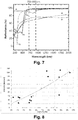
- the importance of the powder diameter spread can be anticipated from Fig. 8 , which shows a correlation of the powder diameter range D90-D10 vs. porosity as measured on the 3D printed object made of noble metals.
- the data points collected in Fig. 8 are based on test carried out by D. Maier and S.
- the problem to be solved by the invention is thus to provide a method and a system for heavy metal powders production by ultrasonic atomization that would overcome disadvantages of the known methods, namely that would be efficient in terms of energy transfer to the raw material and in terms of material losses as well as would allow to obtain a premium quality heavy metal powders even before or without classification process.
- a method of heavy metal powders production by ultrasonic atomization comprises providing a heavy metal raw material in the vicinity of a heat source being an electric arc, heating the heavy raw material by the electric arc, so as to create a molten metal pool on a sonotrode , the molten metal pool having a temperature equal to or greater than the melting temperature (liquidus) of the heavy metal raw material , but below the vaporization temperature of the heavy metal raw material, providing ultrasonic mechanic vibrations by a sonotrode to the molten metal pool, so as to cause the heavy metals droplets being ejected from the molten metal pool, directing the ejected heavy metal droplets away from the molten metal pool, so as the heavy metal droplets freely cool down at least by radiation within a predetermined distance and transform to a heavy metal powder, collecting the heavy metal powder, so as to collect at least 75% of the heavy metal raw material in the form of desirable the heavy metal powder.
- the melting process can be performed more efficiently than other heating methods as e.g. induction heating or by laser beam, because about 80% the electric energy can be transferred directly to the molten metal pool. It is also the most cheapest method of heating to be implemented within an equipment of that size.
- the metal in the pool is kept in liquid form to allow establishing capillary waves on the surfaces of the pool but does not evaporate by causing additional losses of the raw material.
- the cooling time of droplets can be effectively controlled until they cool down into a powder.
- the heavy metal powder can be obtained at a desired location within the closed volume and reduced dimensions of that volume.
- the production method described in this invention allows to reduced size of the atomization chamber particularly for metals of highest density and helps to produce the premium quality heavy and noble metal powders at high yield before or even without the subsequent classification process.
- the method according to the invention can be implemented in a device having small or medium dimensions depending on the used atmosphere and used both in laboratory and industrial applications, when a small amount of very expensive powder is on demand.
- the chamber main dimensions can be less than 1 m in length (in direction of flowing droplets / powder) and 0.3 m on high and diameter.
- the chamber main dimensions can be less than 2 m in diameter and 4 m on high.
- the "vacuum" configuration occupied about 100 more volume, than at process with gas, with similar production output. Nevertheless both configurations are much smaller than typical atomization chambers for gas atomization in the industry, which are scaled to produce at least 50 kg/hr of the powder and preferably more than 200 kg/hr
- the method and the device according to the invention produces highly spherical powder of desirable mean diameter and low span in the particle size distribution.
- powder has high flowability and superior properties, suitable to direct application in 3D printing or sintering without supplementary classification.
- Preferably production output is less than 500 ml/hr of the powder.
- the method for production of heavy metal powders by ultrasonic atomization according to the invention is of particular use for production of heavy metal powders with the process efficacy no more than 1000 ml/hr and preferably less then 500 ml/h of raw material 5.
- Such efficacy is required and well seen by producers of components made of very expensive noble metals, where small amounts of metal powders are used or high costs of raw material 5 makes big scale production unnecessary or impossible due to the limited amount of needed powder or available raw material 5 supply.
- noble and heavy metal elements more preferably gold, silver, copper, platinum, palladium, iridium, ruthenium, rhodium, uranium, tantalum, osmium, hafnium or any alloy composed of them as well other elements, if such alloy meets above density and meting temperature limits.
- the method of production of heavy metal powders according to the invention comprises several steps which are shown in Fig. 1 .
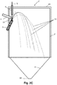
- the method according to the invention can be implemented in a device 1 for production of heavy metal powders according to the embodiment with gas as shown in Fig. 2A and Fig.2B as well as in a device 1' for production of heavy metal powders according to the embodiment with vacuum as shown in Fig.2C .
- the method for producing heavy metal powders according to the invention takes place in a closed volume, namely in a sealed chamber 2 filled or not with a gas 8 (chemically inert).
- the method of production of heavy metal powders according will be described for two different embodiments, the first named hereinafter "in vacuum”, the second one named "with gas”.
- in vacuum is used here as meaning conditions in which the chamber 2' (called hereinafter the vacuum chamber 2') is preferably filled with the gas 8' at reduced pressure in range 0.0001 - 0.01 barA.
- the chamber 2 is filled with the primary gas 8 (chemically inert) at pressure in the range 0.01 to 6 barA, but preferably 1-1.5 barA..
- the method for production of heavy metal powders by ultrasonic atomization begins by a step 100 of providing a heavy metal raw material 5 in the vicinity of a heat source 13.
- the raw material 5 is preferably in the form of a wire or rod, however can be also poured onto the sonotrode 3 as pellets.
- the raw material 5 before entering the closed volume for example the atomization chamber 2 or the atomization vacuum chamber 2' is typically cleaned of dirt (e.g. industrial dust, lubricants after wire production).
- dirt e.g. industrial dust, lubricants after wire production
- feeding can be provided by a feeder arrangement 4, which will be described in reference to Fig. 2B and Fig.2C .
- Next step is a step 200 of melting heavy metal raw material 5 within a molten metal pool 21.
- the heavy metal raw material 5 receives enough thermal energy, in order to heat up from the ambient temperature at supply conditions and then changes its state to a liquid one. As a result, a molten metal is formed within the molten metal pool 21 .
- One of methods to heat the raw material 5 and melt it before an atomization step 300 is to utilize as the heat source 13 an electric arc between a cathode and an anode.
- the cooled cathode 6 can be armed with a non-consumable tungsten electrode 23, while the anode can concurrently work as a vibration source, namely a sonotrode 3, which is also able to conduct electricity. Melting takes place on the sonotrode 3, namely in the molten metal pool 21.
- the low voltage electricity (10-40V) is conducted through vapors emanating from molten raw material so as to create the electric arc 13 between the cathode 6 and the anode 3 (sonotrode).
- the optimum temperature during atomization on the surface of the molten metal pool 21 is around 1.3 times of its melting temperature, however in general the temperature on the surface of the molten metal pool 21 has a temperature equal to or greater than the melting temperature (liquidus) of the heavy metal raw material 5, but below the vaporization temperature of the atomized heavy metal raw material 5
- the pressure in the chamber 2 is supposed to be reduced to range 0.0001 - 0.01 barA for heavy metals, particularly noble elements.
- the best pressure level from above range should be identified for each processed heavy metal composition in following steps:
- the processed raw material 5 is an alloy
- similar analysis is to be performed for the most volatile element in the alloy composition, where the calculation should use the partial vapor pressure.
- the optimum atomization temperature is -1460 K.
- the chamber pressure kept at -100 Pa, the lowest evaporation temperature is obtained for silver (Ag 1575 K, Au 2021 K, Cu 1850 K) and vapors made mostly of silver will keep the electric arc 13 in stable conditions.
- the evaporated part of the silver from the composition will be this way lost and deposited on chamber surfaces, what is one of disadvantages of the embodiment "in vacuum".
- the low voltage electricity (10-40V) is conducted through a shield gas 22 (inert in chemical terms), usually argonium, helium or mixture of both, to create the electric arc 13.
- the length of the electric arc 13 is advantageously in range from 5 to 40 mm between the anode (sonotrode 3) and the cathode (electrode 23).
- the inert gas above the molted metal pool 21 is the shield gas 22 supplied integrally through the heat source 13 in the form of the cooled cathode 6.
- the gas where the electric arc 13 is hold is also partly diluted with a primary gas 8 (also inert) supplied at an inlet 7 and guided by a feature 12 and flowing along the chamber 2 toward an outlet 10 as shown in fig.2A .
- the DC electric arc 13 is created between a tip 23 of the tungsten electrode 6 (cathode) and a sonotrode 3 midpoint (anode), while the feeder 4 of the raw metal material 5 is electrically neutral.
- the electric arc 13 can be created with the use of an alternating current (AC) between the tip 23 of the tungsten electrode 6 and the sonotrode 3 of the same design as in DC version.
- AC alternating current
- step 200 of melting several physical phenomena are taken into account, like thermal conductivity, evaporation rate and enthalpy, reflectivity particularly in infrared wavelength and anode effects (polarization, ionization and thermal electron impact), in order to establish suitable process on the surface of the molten metal pool 21.
- the reflectivity chart for some elements vs. light wavelength is shown in Fig.7 . Doted lines show the dominating range of infrared from the electric arc in the argonium. Those physical phenomena are of the same importance, but of different proportions for "vacuum” or "in the gas” for gas.
- a heating system based on the electric arc 13 is preferably used within the method according to the invention.
- Such heating system based on the electric arc 13 is able to heat up the raw material 5 significantly above its melting point.
- the temperature on the surface of the molten metal pool 21 has a temperature equal to or greater than the melting temperature (liquidus) of the heavy metal raw material 5, but below the full vaporization temperature of the atomized heavy metal raw material 5 .
- the temperature on the surface of the molten metal pool 21 should be kept at temperature at least of the melting temperature of the heavy raw material 5, but below the vaporization temperature of the atomized heavy metal, preferably in range 1.0-1.3 of their melting temperatures expressed in Kelvin degrees, along with the thermal gradient in the molten metal pool 21 as low as possible.
- the temperature on the pool 21 during atomization should reach from 2045 to 2659 deg K or even more to assure process stability and best efficacy.
- the evaporation is to be strictly controlled, if the processes takes place in the "vacuum".
- the pressure in the chamber 2 is supposed to be kept to range 0.0001 - 0.01 barA for heavy metals, particularly noble elements.
- the best pressure level from above range should be identified for each processed heavy metal composition in following steps:
- noble metals have the highest thermal conductivity of all known materials. If one compares silver, copper or gold with either stainless steel or Ni-/Ti-based alloys the thermal conductivity is 5-10 times higher for noble metal in its liquid state. Such high thermal conductivity has a detrimental effect on the durability of the sonotrode 3 used in the atomization step 300. The heat losses from the molten metal pool 21 toward the sonotrode 3 causes heating of the sonotrode 3. This is why on one hand the sonotrode 3 needs to be continuous cooled, otherwise it will be overheated and distressed. On the other hand, high thermal conduction results in reduction of overall thermal efficiency of the method and needs to be compensated by higher energy supplied to the heat source 13, namely by higher current rating in the electric arc 13.
- the electric power supplied to the heat source 13 to melt the heavy metals as defined above does not need to exceed 10 kW per 1 cm 2 of the area of the melting pool 21, in order to allow the production rate up to 1000 ml/hr as well as stabilize thermal and electric conditions on the sonotrode 3 and in the electric arc 13.
- the minimum electric power supplied to the heat source 13 to melt the heavy metals results from the raw material 5 enthalpy and atomization efficacity for desired output and is adjusted case by case.
- the electric power supplied to the heat source 13 is higher as the raw material 5 has to be molten and partly evaporated, while a latent heat of vaporization is important part of enthalpy for this process.
- the electric power does not need to exceed 15 kW per 1 cm 2 of the aera of the melting pool 21, in order to allow the production rate up to 1000 ml/hr
- the shield gas 22 is argonium
- the dominant wavelength of thermal radiation from the electric arc 13 is in the range of 700 - 900 nm, as determined by the spectral lines of the argonium.
- Most of metals have a low or moderate reflectivity in this range of wavelength and can be easily melted by the electric arc 13 e.g. steel, titanium / cobalt / nickel alloys.
- the step 200 of melting heavy metal raw material 5 according to the invention using the electric arc 13 is objectively not highly efficient in terms of energy losses, but it has a lot advantages in terms of implementation simplicity and equipment maintenance costs.
- the step 200 of melting heavy metal raw material 5 according to the invention using the electric arc 13 is objectively not highly efficient in terms of energy losses, but it has a lot advantages in terms of implementation simplicity, low losses of the raw material 5 (due to the negligible evaporation) and small dimensions of the pressurized chamber and maintenance costs.
- the vacuum chamber 2' and design of device 1' for heavy metal powders production is more simple (as shown in Fig.2C ), as the primary gas 8 (e.g. argon) is not supplied at normal pressure and does not be cooled and filtered, although in the "vacuum" the chamber 2' is much larger.
- the primary gas 8 e.g. argon
- the cathode 6 is placed not vertically above the molten metal pool 21, but in the plane XY being parallel to the direction of ejection of the droplets 11 and extending through the longitudinal axis Y of the sonotrode 3, the cathode 6 is positioned above the sonotrode 3 and oriented at an angle ⁇ equal to 0-40 ° measured from the axis X being perpendicular to the direction of ejection of the droplets 11.
- the almost horizontal positions of the cathode 6 offers here the advantage, namely the magnetic fields around the electric arc 13 from the cathode 6 and the cylindrical sonotrode 3 (here also the anode 3) interfere each other, what causes a substantial electric arc blow.
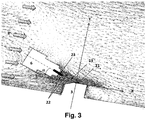
- This blow (marked as an electric arc deflection in Fig. 3 ) is useful and desirable, because it stretches the arc 13 (elongate it), what raises the electric potential in the electric arc 13 and augments the heat generation above the molten metal pool 21.
- the arc blow deflects the electric arc 13 in a way, that it enters in the center of sonotrode 3, where the molten metal pool 21 is intended, as well as where the heat flux toward to pool 21 is more uniform.
- the evaporation of the molted metal is diminished, said evaporation being particularly undesirable for very expensive noble metals.
- the proper position of the cathode 6 versus the sonotrode 3 can increase efficacy of feedstock processing and loss of raw material 5 by avoidance of collision of ejected droplets with a fixture of the cathode.
- the electrode tip 23 is placed at a distance d from the molten metal pool 21, d comprising between 5 and 30 mm, and is inclined in plane XY defined in Fig.2C at an angle ⁇ (not marked) equal to 90 to 50 deg and comprised between the longitudinal axis Y of the sonotrode 3 (i.e. direction of droplet ejection) and the longitudinal axis of the electrode tip 23, preferably the electrode tip 23 being above the molten metal pool 21.
- power rating of the electric system to generate the electric arc 13 is less than 10 kW/cm ⁇ 2 of the area of molted metal pool 21, preferably with the current in the electric arc in the range 80 to 350 A, the electric arc 13 length i.e.
- the cathode 6 and the electric arc 13 are above the sonotrode 3 and inclined in plane XY defined in Fig.2B at an angle ⁇ (not marked) equal to 90 to 50 deg and comprised between the longitudinal axis Y of the sonotrode 3 and the longitudinal axis of the electrode tip 23 as shown in Fig.2B .
- ⁇ not marked
- the above thermal efficiency can be defined as proportion of thermal energy received in continuous manner by the heavy metal raw material 5 kept in liquid state to the electric energy provided to the heat source 13.
- the lowest efficiency is reached for highly reflexive noble metals like silver and gold, and metals of very high melting temperatures, usually > 2023 deg K, because of inevitable losses of energy for cooling of critical systems items like the sonotrode 3 and the electrode 6 (the cathode 6), in order to assure their long life.
- the above heat transfer in the step 200 of melting the heavy metal raw material 5 by the electric arc 13 can be ameliorated by an augmented convection or change of radiation wavelength between the extremely hot gas in the electric arc 13 and molten metal pool 21.
- such increased heat transfer by convection or modified radiation can be obtained by selection of the arc shield gas 22 (chemically the inert gas) as a mixture of argonium and helium, where preferably He > 10% per volume.
- the arc shield gas 22 chemically the inert gas
- helium has the dominant spectral lines in range 580 - 720 nm, hence with wavelength of lower reflexivity (in reference to argonium) for most metals of interest.
- helium electrical properties allow to reach higher electric potential in the electric arc 13. It means that for the same level of current, higher electric energy is transferred through the electric arc 13, what allows to generate much higher heat flux on the same area of the molten metal pool 21 (e.g. -40 % more for mixture Ar70% + He30% vs. pure argonium).
- Helium electrical properties allow to reach higher heat generation in the electric arc 13 due to the fact that the arc voltage is significantly increased by the addition of helium, as it has a higher ionization voltage than argon in the electric arc 13. This tendency is due to the fact that the electric potential in the cathode region clearly increases, when helium is added up to the content 75% of helium. It is also due to the fact that the potential gradient of the arc column and the potential in the anode region remain virtually constant up to a helium content of 75%.
- the heat input absorbed in the anode increases, when helium is added to the argon arc. This tendency is due, not to an increase in the amount of energy transport due to electron flux and anode effect, but to an increase in the energy transport due to more intensive heat conduction and transfer from the plasma rich in helium. As results the heat transferred from the electric arc 13 to the molted metal pool 21 of highly reflexive metals is significantly improved.
- the shield gas 22 for the electric arc 13 can be supplied in amount 8 to 30 l/min.
- the shield gas 22 composed of argonium with 10 to 75 % addition of helium per volume increases its thermal conductivity above the molten metal pool 21, what helps to melt the raw material 5 as well as modifies the spectral emissivity of the electric arc 13 to lower wavelengths, what is desirable for highly reflexive metals.
- said mixture of Ar+He shield gas 22 can be used for melting of copper, silver, gold and their alloys or material with melting temperature > 2023 C like platinum, rhodium and iridium.
- the augmented convection or tuning of radiation wavelength between the ionized shield gas 22 and the molten metal pool 21 is not feasible, so the electric energy conversion to heat is not efficient as "with gas".
- the heat to melt / vaporize the raw material 5 is generated mostly by anode effect and partly by radiation of the heat from the electric arc 13 toward the molten metal pool 21.
- the electric arc 13 length is shorter in the embodiment in the "vacuum", preferably the electric arc 13 length being 5 to 30 mm.
- the ionization energy of the vaporized noble metals is lower by -45% than of the shield gas 22 (like argon) This results in both effects limiting the electric arc 13 voltage and a force to keep the electric arc being at -50% higher current rating in comparison with the embodiment "with gas".
- the raw material 5 can be pre-heated by an additional heat source (not shown) to a temperature up to 70% of its melting temperature in Kelvin degrees.
- an additional heat source (not shown) to a temperature up to 70% of its melting temperature in Kelvin degrees.
- the demand for electric energy consumption in the main heat source 13, namely the electric arc can be reduced and overall energy conversion within the method and the device according to the invention improved.
- a pre-heating is advantageous particularly in case of the raw material 5 of very high melting temperature (> 2023 deg K).
- the additional heat source can be an auxiliary induction heating source, for example a coil installed around the wire in the feeder 4.
- the additional heat source can be optionally ventilation of the feeder 4 with a hot secondary gas 15 e.g. recirculated from hot area of the chamber 2 with similar effect as described above.
- the DC electric arc 13 is modified by the current pulsations in the range of 50 - 350 Amp and at low frequency between 20 and 1000 Hz, preferably 50 - 400 Hz, in order to boost the long capillary waves on the surface of the molten metal pool 21 and intensify mixing of liquid metal and wettability on the interface between the molten metal 21 and the sonotrode 3 center.
- This DC power modification by current pulsation is advantageous for both embodiments: in the "vacuum” and "with the gas”.
- Such modification also allows in both embodiments: in the "vacuum” and "with the gas”, to improve process efficiency, if the pulsation of the electric arc 13 are synchronized with same frequency pulsation of ultrasonic vibrations in the sonotrode 3 during the step 300. Namely less energy must be supplied by the ultrasonic transducer (not shown on figures) to reach atomization threshold in the molted metal pool 21. Moreover during phase when the electric arc 13 is decreased, the Lorenz forces acting on electrically charged droplets 11 (ejected from the anode 3) are the lowest, what diminishes electric losses in electromagnetic field around the electric arc 13 and the sonotrode 3 at the beginning of the step 400, hence improves overall energy conversion from supplied electricity to the device 1 vs. enthalpy and kinetic energy of droplets 11 of atomized heavy metal.
- a low frequency pulsation in range of 20 to 1000 Hz, more preferably 50 to 400 Hz helps as follow: in case of DC electric arc pulsation, it generates long capillary waves on the surface of the molten metal pool 21 and intensify mixing of liquid metal as well as reduces the thermal gradient in the molten metal pool 21. Such mixing uniforms the temperature on the surface of the molten metal pool 21 and helps to better control the evaporation rate in the point, where the electric arc 13 is directed (the electric arc temperatures 10000 - 15000 K above the surface of the pool 21).
- both pulsations on DC electric arc 13 and ultrasonic transducer can be synchronized the way, the peak level of electric arc 13 occurs concurrently with low power consumption on the transducer.
- the current should be in range 150 - 350 amp.
- the revers action should take place during 60 to 90% of the cycle time, when the atomization is maximized and heating diminished with the current in the range 50 - 150 A.
- the electric arc 13 can be of AC type in the range of 80 - 350 A at a frequency between 100 and 50000 Hz, preferably at a frequency in the range of 5 to 50% of ultrasonic frequency of the sonotrode 3, more preferably at one of fraction 1/10, 1/9, ... , 1/4 or 1/3 of the ultrasonic frequency at the sonotrode 3 as in the step 300.
- the AC electric arc 13 generates the secondary capillary waves of sub-synchronous frequency on the molten metal pool 21 surface and enhance the instability of the capillary waves at frequency driven by the sonotrode 3 as well as improves wettability of interface between the molten metal pool 21 and the surface of the sonotrode 3.
- a threshold of atomization for required sonotrode 3 vibrations is lowered and the entire process can be continued with lower electric energy consumption.
- step 300 of the ultrasonic atomization involves providing mechanic vibrations to the molten metal pool 21, so as to cause the heavy metals droplets being ejected from the molten metal pool 21.
- the capillary waves generated in the liquid metal pool 21 are utilized. Said capillary waves are generated by the ultrasonic vibrations from the transducer (not shown) attached to the cold end of the sonotrode 3. In this way the pool 21 of molten raw material 5 is subjected at its bottom to vibrations coming from the sonotrode 3. To effectively transfer these vibrations (i.e.
- Said step 300 of ultrasonic atomization comprises ejecting droplets 11 of molten heavy metal from a hot end of said sonotrode 3, if the vibrations exceed a critical value specific for the molten metal at given temperature. This condition is meant as atomization threshold and can be lowered (i.e. liquid metal is more prone to atomization) by reduction of its viscosity, what is visibly correlated with the molten metal pool 21 temperature.
- the surface of the molten metal pool 21 have to reach temperature around 1.3 melting temperature (liquidus) in deg Kelvin or even higher, in order to reduce the metal viscosity appropriately.
- some metals e.g. silver and alloys with more volatile elements
- uncontrolled overheating can accelerate their evaporation, because of high vapor pressure at higher temperature.
- any ultrasonic atomization ejects droplets 11 of stable diameter (D50 by default) with a rate proportional to ultrasonic vibrations (meant as number of oscillation cycles in a time frame). Therefore the production output of the system is usually defined as a volumetric rate (e.g. ml/hr) as multiplication of droplet 11 ejections number and their size expressed by a droplet volume (assuming that a droplet 11 is spherical).
- a volumetric rate e.g. ml/hr
- Such output parameter is specific for a given atomization device, which is usually versatile to atomize different metals.
- parameters of the ultrasonic atomization step 300 can be adjusted so as to melt and atomize elements and alloys of density of at least 8500 kg/m ⁇ 3 and melting temperature of at least 1073 deg K (liquidus), preferably gold, silver, copper, platinum, palladium, iridium, ruthenium, rhodium, uranium, osmium, tantalum, hafnium and their alloys of the content >40% per weight, if they meet stated limits for density and melting temperature.
- the power rating of the ultrasonic transducer, which generates vibrations in the sonotrode 3 and then in the molten metal pool 21 is at least 30 W/cm ⁇ 2 of the area of the molten metal pool 21 and the transducer frequency is continuously or periodically kept at any setpoint in the range from 15 to 1000 kHz. This is true for both embodiments, namely in the "vacuum” as well for “with the gas", because the surface tension of molten metal is almost same at pressures in range 0 - 6 barA
- the amplitude of the vibration velocity on the sonotrode 3 hot end is at least 0.2 m/sec 0-peak, in order to eject the droplets 11 of diameters up to 100 microns on the altitude in range 20 and 400 mm above the molten metal pool 21, if its density meet the density and melting temperature criteria as stated in the previous paragraph.
- the ultrasonic vibrations as above can provide a secondary advantage due to the fact, that shaking of the molten metal pool 21 as provided by ultrasonic vibration allow to improve heat transfer between the pool 21 and the electric arc 13 in reference to non-vibration case.
- shaking the molten metal pool 21 by ultrasonic vibration can be utilized to boost the thermal convection between the molten metal pool 21 and the hot (shield) gas 22 in the electric arc 13, hence improve overall heat transfer from the gas to the molten metal pool 21, if the conventional means, like based on radiation are not effective enough - as in case of noble metals of high reflexivity.
- Next step of the method for production of heavy metal powders is a step 400 of directing and transporting heavy metal droplets 11 outside the molten metal pool 21 along with their cooling down, so as their temperature decreases below 70% of their melting temperature in degrees Kelvin before the metal droplets 11 reach (collide) any surface.
- the directing and transporting of heavy metal droplets 11 is performed in a controlled manner both for the embodiment "in vacuum” as well “with gas”.
- the heat (enthalpy) from the droplets 11 / powder 11' is taken away during their freely cooling down by radiation (both in “vacuum” and “with gas”) and convection ("with gas” only).
- the term 'freely' means that the droplets 11 cool down before they reach any surface. More heat can be taken away by gas, particularly at elevated pressure (>1 barA).
- the heat is to be radiated out to the chamber walls and then to the ambience.
- additional cooling action directed to the chamber wall is required for the embodiment with the vacuum.
- Such cooling action is optional for the embodiment with the pressurized chamber 2.
- a controlled directing and transporting of the metal droplets 11 is controlled by following: vector of initial kinetic energy (provided by the ultrasonic vibrations on the sonotrode 3), Lorenz forces driven by the electromagnetic field in vicinity of the electric arc 13, gravity acceleration, aerodynamic drag and viscosity forces of the gas 8 acting on the droplets 11.
- the last two forces related to the gas 8 can be intensified, if the gas 8 is provided at higher pressure (e.g. > 1 barA), what allows to shorten cooling time and the trajectory for droplets 11 between the sonotrode 3 and the chamber outlet 10, if the compact size of the device 1 is needed.
- the gas directing the ejected heavy metal droplets 11 involves additionally intercepting them by a controlled stream of the gas 8
- the same forces acts on the droplets 11 except aerodynamic drag and viscosity forces of the gas 8', which are negligible, if gas pressure is below 0.01 barA.
- the droplets cooling time and the trajectory are about 3 times longer than "with the gas”, hence the vacuum chamber 2 should be of much larger dimensions and volume than the chamber 2 pressurized with gas.
- a controlled directing and transporting of the metal droplets 11 is carried out with the use of a cold primary gas 8, preferably mixed with much smaller amount of the shield gas 22 departing the cathode 6.
- the heavy metal droplets 11 ejected during the atomization step 300 should leave the molten metal pool 21 in a specific direction, preferably vertical one, otherwise the droplets of high initial velocity or of larger diameters (more close to D90) are likely to hit the walls of the chamber 2 (which is small) in a random manner forming deposits there and causing material losses.
- the metal droplets 11 are entrained by the cold primary gas 8 within the chamber 2, so as to control their trajectories and cool down below their melting temperature, hence changing its state to solid one and form a powder 11'.
- the flow of the primary gas 8 is guided first upstream of the sonotrode 3. Then, the flow of the primary gas 8 combines with the flow of the shield gases 22 in the vicinity of the heat source 13, and together is directed above and downstream of the sonotrode 3, where a part of the heat in the shield gas 22 exiting the electric arc 13 is diluted by the primary 8 and optionally secondary 15 gases.
- the flow direction of combined streams of the primary gas 8 and the shield gas 22 is shown on Fig. 3 . In particular, it is shown the primary gas 8 flow and the shield gas 22 flow (gray arrows) around the sonotrode 3 and the heater 13. Dotted line in Fig.3 marks an electric arc 13 under the blow from magnetic field.
- the primary gas 8 and the shield 22 gas can be argon or a mixture of argon with helium.
- the shield gas 22 has higher helium content, then the primary gas 8.
- a mixture of argon and helium is supplied to the chamber 2 at temperature below 150 C, more preferably below 50 C by at least one gas inlet 7. The volumetric inflow of these gases is based on simulation of droplets trajectories and their cooling time for demanded droplets diameters range (from D10 to D90) and mass.
- the volumetric inflow of the inert primary gas 8 should be preferably of the average velocity > 0.5 m/s in part of the chamber 2, where the droplets flow is anticipated i.e. downstream of the sonotrode 3.
- the gases 8, 22 can be supplied at elevated pressure (> 1 barA) to take advantage of their higher volumetric heat capacity to enhance cooling of heavy metals with high level of enthalpy. This also allows to keep compact size of the system (chamber, separation unit, piping, cooling unit) for scaled up output, if required.
- the step 400 of directing and transporting heavy metal droplets 11 comprises keeping the gas flow parallel to a major axis (not marked) of the chamber 2 at specific velocity threshold which is > 0.25 m/sec, preferably > 0.5 m/s, measured as average value across the plane perpendicular to the major (longitudinal) axis of the chamber 2. In such conditions, heavy metal droplets 11 deflect their trajectories with the aid of the aerodynamic drag forces.
- the flow distribution of the incoming primary gas 8 in the chamber 2 can be preferably obtained by designing specific means in each part of the chamber 2 (see Fig. 2A ), for example by designing at least one gas inlet 7 port with help of CFD modeling, and/or providing guiding means like at least one deflector 12 and/or providing an inflow of a secondary hot gas 15 from at least one other hot gas inlet port 14 than the primary gas inlet 7.
- the cooling function in step 400 of transporting heavy metals droplets 11 can be optionally augmented for the embodiment "with the gas” and in the "vacuum”, if the side walls of the chamber 2, 2' and the converging outlet 9 of the outlet port 10, for example in the form of a channel, are additionally cooled, e.g. with a water jacket or external chamber radiators 24(as shown in Fig. 2c ), to dissipate more heat by radiation and convection to ambience.
- next step of the method according to the invention is a step 500 of separation of the heavy metal powder from the combined gas streams of the primary gas 8 and the shield gas 22, as well as optionally hot secondary gas 15 and then regeneration of the gas mixture (8, 22, 15).
- the separation can utilize means like separation on a cyclone or filtration or both together.
- the stream of the powder 11' moved by the warm gas mixture (8, 22, 15) which usually has temperature 343 - 473 deg K as at the end of the step 400, is directed to the cyclone (not shown).
- the cyclone performs selection of particles of the heavy metal powder 11' from low density gas mixture (8, 22, 15) through the vortex separation.
- the heavy metal powder 11' is collected, as final product of the method according to the invention, in a container (not shown in Fig.2A ) on the cyclone bottom, while the combined inert gases (mixture 8, 22, 15) with small particles (i.e. dust of diameter below D10 for product) is departing from the cyclone on its top. Then the inert gas mixture (8, 22,15) can be filtered out of dust, so that to receive again clean inert gas 8, 22,15. Then the combined inert gas is recycled after external cooling back to the process in step 300 as the cold primary gas 8.
- the inert gases mixture 8, 22, 15
- small particles i.e. dust of diameter below D10 for product
- the droplets 11 of expensive noble metal which reach accidentally the surface of the chamber 2, can be retrieved after the device 1 is shut down.
- the powder 11' collected on the inner surfaces of the chamber 2 can be manually scraped (e.g. by brush).
- the noble metal dust or deposited vapors accumulated on such coating can be removed occasionally with chemical means (e.g. acids) along with said coating. Then coating is reapplied.
- the powder 11' received in the step 500 i.e. final product of the method meets all together criteria, before classification on separate sieve, as follow:
- the device 1 dedicated to production of the heavy metal powders by the ultrasound atomization in the embodiment with the gas namely the ultrasonic atomizer 1 suitable to produce the heavy metal powders according to present invention such as platinum, silver, palladium, gold, copper alloy has been designed and tested by the Applicant.
- the ultrasonic atomizer 1 suitable to produce the heavy metal powders according to present invention such as platinum, silver, palladium, gold, copper alloy.
- the device 1 was equipped with the cooled sonotrode 3 sized to generate vibrations at 35 kHz and can be easily upgraded to other frequencies on request, in order to produce powder of other D50.
- the primary gas 8 and the shield gas 22 were both argon and delivered to the chamber 2 at temperature 293 deg K.
- the cathode 6 was a non-consumable tungsten electrode 6 which had a diameter of 3 mm and was generating electric arc 13 of rating in range 1200 to 8200 W to melt the above mentioned metals.
- the area of the molten metal pool 21 was 110 to 180 mm 2 for different versions of the sonotrode 3.
- the example of trajectories of droplets 11/ the powder 11' for few metals is shown in Fig. 6A .
- the atomization chamber 2 is substantially longer in a direction perpendicular to the direction of the ejection of droplets 11 from the sonotrode 3 (i.e the longitudinal axis of the sonotrode within the plane AA as shown in Fig.2A ), while overall assembly of the chamber 2 is tilted down by 10 deg as shown also in Fig. 2A and the sonotrode 3 is in general oriented vertically up or tilted by same angle (as shown also in Fig. 2A ).
- the length and diameter (or at least height) of the chamber 2 are selected after a simulation of trajectory of droplets 11 by CFD models. These trajectories are dependent on:
- the initial velocity of the droplets 11 ejected from the sonotrode 3 is comparable to the velocity amplitude V s of sonotrode 3 hot surface, where the droplets 11 are formed by capillary waves on the surface of the molten metal pool 21.
- the chamber 2 has the primary gas inlet 7 on its one (cold) end, and on the opposite a converging (tapered) outlet 10 of the hot gas - powder mixture, joined to the powder and gas separating device, preferably a cyclone, where the product i.e.
- the primary gas inlet 7 is extended with a deflector feature 12, which is used to distribute clean and pre-cooled primary gas 8 along the chamber 2.
- Streamlines of the primary gas 8 are substantially perpendicular to the ejection direction of molten metal 21 from the sonotrode 3, in order to reject the heat emitted from the region of the electric arc 13.
- the electric arc 13 is generated by the electrode 6, which is preferably equipped with a non-consumable tungsten electrode tip 23.
- the sonotrode 3 here is an anode and the electrode 6 a cathode.
- the raw material 5 is delivered to the molten metal pool 21 in the form of wire through the feeder 4.
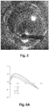
- An exemplary photo of the inside of the chamber 2 during the atomization process according to the invention is shown in Fig.5 .
- the wire feeder 4 On the left it can be seen the wire feeder 4, on the right the cathode 6 while bright spots in the center are the Pt droplets 11.
- the function of the deflector feature 12 is to uniform the primary gas 8 flow profile around the sonotrode 3 and the cathode 6, what reduces turbulence and temperature above the molten metal pool 21, stabilizes the atomization process and helps maintain the desired temperature in the molten metal pool 21.
- Shown on the plot in Fig.6A is the practical minimum distance [meters] from an ejection point to meet temperature criteria ⁇ 70% of the melting temperature in Kelvin degrees in order to avoid sticking of droplets 11 and/or the powder 11' to the surfaces of the chamber 2.
- the chamber 2 is configured so as to have the smallest possible dimensions.
- the smallest as possible volume of the chamber reduces the amount of the inert gas from all streams (primary, secondary and shield) in the system and reduces the start-up time necessary to exchange the atmosphere from air to clean inert gas (i.e. oxygen free).
- the chamber 2 is universal for various metals and their alloys - by choosing the amplitude on the sonotrode 3 and primary gas velocity profiles (optionally their temperature and pressure), one can simply control the droplet / powder trajectory in the density range from medium (like 8500 kg/m ⁇ 3 for copper) to very heavy (like 21450 kg/m ⁇ 3 for platinum).
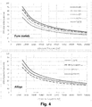
- Charts in Fig. 4 show examples of the powder dimeter range in function of ultrasonic frequency on the sonotrode 3 for: on top - pure metals, on bottom - alloys.
- FIG. 2C Aspects of the installation example in the "vacuum” is shown in Fig. 2C .
- the device 1' for the embodiment in the “vacuum” is more simple, but the chamber 2 itself requires larger dimensions.
- the same reference numbers are used to indicate the same elements of the device 1' as shown in Fig. 2A and 2B , which refer to the device 1.
- the walls of the vacuum chamber 2' require some external cooling features 24, like radiator or water jacket. Such features are optionally for the pressurized chamber 2 as shown in Fig.2A and Fig.2B .
- Fig.6B Moreover shown on the plot in Fig.6B is the practical minimum distance [meters] from an ejection point to meet temperature criteria ⁇ 70% of the melting temperature in Kelvin degrees in order to avoid sticking of droplets 11 and/or the powder 11' to the chamber surfaces at same process conditions as assumed in Fig 6A .
- trajectories in the vacuum chamber must be much longer (about 4 times more, than in gas at pressure 1barA) in order to properly cool down the droplets below the above temperature limit. This explains, why the overall dimension of the "vacuum" chamber 2 are several times larger than the "pressurized" chamber 2.
- Such powders have been produced on the device 1 as described earlier for the embodiment 'with gas'. Then, without any prior classification, their statistical distributions were examined on the KEYENCE VHX-6000 microscope. The particle size distribution of the powder was measured by the Heywood's method. The photos of the particles in microscopic view for powders are shown on Fig. 9 and Fig. 10 . The properties of the powders are in the Table 2 as below Table 2. PSD and Sphericity for the platinum and copper alloy powders after atomization at 35 kHz without further classification.
Landscapes
- Engineering & Computer Science (AREA)
- Chemical & Material Sciences (AREA)
- Manufacturing & Machinery (AREA)
- Materials Engineering (AREA)
- Automation & Control Theory (AREA)
- Health & Medical Sciences (AREA)
- Optics & Photonics (AREA)
- Plasma & Fusion (AREA)
- Physics & Mathematics (AREA)
- General Health & Medical Sciences (AREA)
- Toxicology (AREA)
- Mechanical Engineering (AREA)
- Nanotechnology (AREA)
- Manufacture Of Metal Powder And Suspensions Thereof (AREA)
- Powder Metallurgy (AREA)
- Physical Or Chemical Processes And Apparatus (AREA)
Priority Applications (3)
| Application Number | Priority Date | Filing Date | Title |
|---|---|---|---|
| US17/619,548 US12090554B2 (en) | 2019-07-16 | 2020-07-14 | Method and device for producing heavy metal powders by ultrasonic atomization |
| PCT/IB2020/056633 WO2021009683A1 (en) | 2019-07-16 | 2020-07-14 | Method and device for producing heavy metal powders by ultrasonic atomization |
| US18/788,669 US20240390977A1 (en) | 2019-07-16 | 2024-07-30 | Method and device for producing heavy metal powders by ultrasonic atomization |
Applications Claiming Priority (1)
| Application Number | Priority Date | Filing Date | Title |
|---|---|---|---|
| PL430614A PL430614A1 (pl) | 2019-07-16 | 2019-07-16 | Sposób usuwania proszku wytworzonego w procesie atomizacji ultradźwiękowej i urządzenie do realizacji tego sposobu |
Publications (2)
| Publication Number | Publication Date |
|---|---|
| EP3766611A2 true EP3766611A2 (de) | 2021-01-20 |
| EP3766611A3 EP3766611A3 (de) | 2021-02-17 |
Family
ID=72291065
Family Applications (2)
| Application Number | Title | Priority Date | Filing Date |
|---|---|---|---|
| EP20179851.9A Pending EP3766611A3 (de) | 2019-07-16 | 2020-06-12 | Verfahren und vorrichtung zur herstellung von schwermetallpulvern durch ultraschallzerstäubung |
| EP20764444.4A Pending EP3999267A1 (de) | 2019-07-16 | 2020-07-16 | Verfahren zur evakuierung von durch ultraschallzerstäubung produziertem pulver und vorrichtung zur implementierung dieses verfahrens |
Family Applications After (1)
| Application Number | Title | Priority Date | Filing Date |
|---|---|---|---|
| EP20764444.4A Pending EP3999267A1 (de) | 2019-07-16 | 2020-07-16 | Verfahren zur evakuierung von durch ultraschallzerstäubung produziertem pulver und vorrichtung zur implementierung dieses verfahrens |
Country Status (5)
| Country | Link |
|---|---|
| US (2) | US12090554B2 (de) |
| EP (2) | EP3766611A3 (de) |
| CN (1) | CN113993642B (de) |
| PL (1) | PL430614A1 (de) |
| WO (2) | WO2021009683A1 (de) |
Cited By (7)
| Publication number | Priority date | Publication date | Assignee | Title |
|---|---|---|---|---|
| CN113957430A (zh) * | 2021-09-29 | 2022-01-21 | 西安交通大学 | 一种热-超声刮涂装置及刮涂方法 |
| CN114042925A (zh) * | 2021-11-29 | 2022-02-15 | 湖南天际智慧材料科技有限公司 | 一种雾化室预热装置 |
| CN114054765A (zh) * | 2021-11-12 | 2022-02-18 | 广州赛隆增材制造有限责任公司 | 制粉装置和制粉方法 |
| CN114632944A (zh) * | 2022-02-18 | 2022-06-17 | 武汉大学 | 一种基于多能场的异种材料增材制造方法 |
| CN115216656A (zh) * | 2022-03-05 | 2022-10-21 | 哈尔滨工业大学 | 超声处理改变Nb-Si合金韧性相形态的装置及方法 |
| CN118635537A (zh) * | 2024-07-03 | 2024-09-13 | 广东雷佳增材科技有限公司 | 用于slm成形梯度材料的超声波无接触式铺粉方法及系统 |
| CN119406652A (zh) * | 2024-12-02 | 2025-02-11 | 西北工业大学 | 雾化装置、雾化方法和应用 |
Families Citing this family (11)
| Publication number | Priority date | Publication date | Assignee | Title |
|---|---|---|---|---|
| US12378643B2 (en) | 2019-01-18 | 2025-08-05 | Divergent Technologies, Inc. | Aluminum alloys |
| WO2023278878A1 (en) | 2021-07-01 | 2023-01-05 | Divergent Technologies, Inc. | Al-mg-si based near-eutectic alloy composition for high strength and stiffness applications |
| CN115090891A (zh) * | 2022-08-25 | 2022-09-23 | 西安赛隆增材技术股份有限公司 | 一种等离子旋转电极雾化制粉设备与制粉方法 |
| WO2024086817A2 (en) * | 2022-10-20 | 2024-04-25 | Divergent Technologies, Inc. | Alloying via ultrasonic atomization |
| CN117102489A (zh) * | 2023-08-29 | 2023-11-24 | 北京理工大学唐山研究院 | 一种适用于超声雾化制粉的可加热雾化板组件 |
| CN117102492A (zh) * | 2023-08-29 | 2023-11-24 | 北京理工大学唐山研究院 | 冷坩埚感应熔炼-超声雾化粉体制备系统及应用方法 |
| CN117718480A (zh) * | 2023-08-29 | 2024-03-19 | 北京理工大学唐山研究院 | 无吹粉电子束加热式超声雾化制粉设备及其应用方法 |
| CN117245095A (zh) * | 2023-09-21 | 2023-12-19 | 南京尚吉增材制造研究院有限公司 | 真空自耗电弧熔炼超声雾化制粉系统及方法 |
| CN118127331B (zh) * | 2024-03-13 | 2025-03-14 | 湖南西鼎新材料有限公司 | 一种废铝回收用筛选机 |
| CN120901294B (zh) * | 2025-10-10 | 2025-12-05 | 天津铸金科技开发股份有限公司 | 一种旋转电极雾化制粉控制系统及控制方法 |
| CN121339455A (zh) * | 2025-11-04 | 2026-01-16 | 沈阳工业大学 | 一种利用粗/废粉末通过超声雾化制备球形金属细粉的方法 |
Citations (5)
| Publication number | Priority date | Publication date | Assignee | Title |
|---|---|---|---|---|
| US3275787A (en) | 1963-12-30 | 1966-09-27 | Gen Electric | Process and apparatus for producing particles by electron melting and ultrasonic agitation |
| DE3150221A1 (de) | 1981-12-18 | 1983-07-21 | Leybold-Heraeus GmbH, 5000 Köln | Verfahren und vorrichtung zur herstellung von metallpulver aus einer schmelze |
| CN1422718A (zh) | 2001-12-04 | 2003-06-11 | 北京有色金属研究总院 | 球形金属粉末的超声雾化制备方法及装置 |
| EP3216545A1 (de) | 2016-03-07 | 2017-09-13 | Heraeus Deutschland GmbH & Co. KG | Edelmetallpulver und dessen verwendung zur herstellung von bauteilen |
| WO2019092641A1 (en) | 2017-11-09 | 2019-05-16 | 3D Lab Sp. Z O.O. | Device for the manufacturing of spherical metal powders by an ultrasonic atomization method |
Family Cites Families (20)
| Publication number | Priority date | Publication date | Assignee | Title |
|---|---|---|---|---|
| SE394604B (sv) * | 1974-12-18 | 1977-07-04 | Uddeholms Ab | Forfarande och anordning for pulvertillverkning genom granulering av en smelta |
| DE2656330C2 (de) * | 1976-12-13 | 1984-03-15 | Battelle-Institut E.V., 6000 Frankfurt | Verfahren und Vorrichtung zur Herstellung von Pulvern oder Granulaten aus Metallen und Legierungen |
| SE425837B (sv) * | 1979-05-31 | 1982-11-15 | Asea Ab | Anleggning for gasatomisering av en smelta, innefattande kylorgan |
| JPS61295306A (ja) * | 1985-06-24 | 1986-12-26 | Kawasaki Steel Corp | 金属微粉末の製造方法およびその装置 |
| CA1315055C (en) * | 1986-03-10 | 1993-03-30 | John Joseph Fischer | Atomization process |
| JP2001226705A (ja) * | 2000-02-15 | 2001-08-21 | Hitachi Metals Ltd | 微細金属球の製造方法並びに微細金属球製造装置 |
| US6444009B1 (en) * | 2001-04-12 | 2002-09-03 | Nanotek Instruments, Inc. | Method for producing environmentally stable reactive alloy powders |
| JP2003138303A (ja) * | 2001-10-29 | 2003-05-14 | Nissei Techno:Kk | 超音波式金属粉末作成装置 |
| FI121990B (fi) * | 2007-12-20 | 2011-07-15 | Beneq Oy | Laite sumun ja hiukkasten tuottamiseksi |
| CN102335743B (zh) * | 2011-08-25 | 2013-05-01 | 西北工业大学 | 一种超声喷射成形方法 |
| KR101512772B1 (ko) * | 2013-05-14 | 2015-04-22 | 부산대학교 산학협력단 | 금속 분말을 제조하기 위한 방법 및 아토마이저 장치 |
| CN103433499B (zh) * | 2013-08-27 | 2015-08-12 | 湖南航天工业总公司 | 一种球形金属粉末的超声雾化制备装置及制备方法 |
| CN105855558B (zh) * | 2016-05-31 | 2018-01-16 | 宝鸡万品金属科技有限公司 | 用超声波振动雾化制备微细球状金属粉末的设备及工艺 |
| CN106513692B (zh) * | 2016-12-30 | 2018-05-25 | 长沙新材料产业研究院有限公司 | 一种用于生产粉末的雾化喷嘴及方法 |
| CN107138733B (zh) * | 2017-07-10 | 2019-07-02 | 山东科技大学 | 超声振动雾化制备金属粉末的装置、方法以及3d打印系统 |
| CN107824793B (zh) * | 2017-10-31 | 2020-12-15 | 中国科学院过程工程研究所 | 一种制备超细单分散金属微球的装置及方法 |
| CN108436093A (zh) * | 2018-04-23 | 2018-08-24 | 安徽哈特三维科技有限公司 | 一种采用坩埚气雾化法制备铁基球形金属粉体的超音速雾化器 |
| CN109317687B (zh) * | 2018-10-30 | 2024-06-14 | 湖南天际智慧材料科技有限公司 | 一种超声波振动雾化室及由其组成的雾化制粉设备 |
| CN110116214A (zh) * | 2019-04-26 | 2019-08-13 | 西北工业大学 | 微米级均匀锡合金球侧向扰动喷射制备装置 |
| CN113909492B (zh) * | 2021-09-24 | 2022-08-16 | 西北工业大学 | 一种带小回流区的金属微滴喷射装置 |
-
2019
- 2019-07-16 PL PL430614A patent/PL430614A1/pl unknown
-
2020
- 2020-06-12 EP EP20179851.9A patent/EP3766611A3/de active Pending
- 2020-07-14 WO PCT/IB2020/056633 patent/WO2021009683A1/en not_active Ceased
- 2020-07-14 US US17/619,548 patent/US12090554B2/en active Active
- 2020-07-16 EP EP20764444.4A patent/EP3999267A1/de active Pending
- 2020-07-16 CN CN202080043681.3A patent/CN113993642B/zh active Active
- 2020-07-16 WO PCT/IB2020/056702 patent/WO2021009708A1/en not_active Ceased
-
2024
- 2024-07-30 US US18/788,669 patent/US20240390977A1/en active Pending
Patent Citations (5)
| Publication number | Priority date | Publication date | Assignee | Title |
|---|---|---|---|---|
| US3275787A (en) | 1963-12-30 | 1966-09-27 | Gen Electric | Process and apparatus for producing particles by electron melting and ultrasonic agitation |
| DE3150221A1 (de) | 1981-12-18 | 1983-07-21 | Leybold-Heraeus GmbH, 5000 Köln | Verfahren und vorrichtung zur herstellung von metallpulver aus einer schmelze |
| CN1422718A (zh) | 2001-12-04 | 2003-06-11 | 北京有色金属研究总院 | 球形金属粉末的超声雾化制备方法及装置 |
| EP3216545A1 (de) | 2016-03-07 | 2017-09-13 | Heraeus Deutschland GmbH & Co. KG | Edelmetallpulver und dessen verwendung zur herstellung von bauteilen |
| WO2019092641A1 (en) | 2017-11-09 | 2019-05-16 | 3D Lab Sp. Z O.O. | Device for the manufacturing of spherical metal powders by an ultrasonic atomization method |
Cited By (7)
| Publication number | Priority date | Publication date | Assignee | Title |
|---|---|---|---|---|
| CN113957430A (zh) * | 2021-09-29 | 2022-01-21 | 西安交通大学 | 一种热-超声刮涂装置及刮涂方法 |
| CN114054765A (zh) * | 2021-11-12 | 2022-02-18 | 广州赛隆增材制造有限责任公司 | 制粉装置和制粉方法 |
| CN114042925A (zh) * | 2021-11-29 | 2022-02-15 | 湖南天际智慧材料科技有限公司 | 一种雾化室预热装置 |
| CN114632944A (zh) * | 2022-02-18 | 2022-06-17 | 武汉大学 | 一种基于多能场的异种材料增材制造方法 |
| CN115216656A (zh) * | 2022-03-05 | 2022-10-21 | 哈尔滨工业大学 | 超声处理改变Nb-Si合金韧性相形态的装置及方法 |
| CN118635537A (zh) * | 2024-07-03 | 2024-09-13 | 广东雷佳增材科技有限公司 | 用于slm成形梯度材料的超声波无接触式铺粉方法及系统 |
| CN119406652A (zh) * | 2024-12-02 | 2025-02-11 | 西北工业大学 | 雾化装置、雾化方法和应用 |
Also Published As
| Publication number | Publication date |
|---|---|
| CN113993642A (zh) | 2022-01-28 |
| EP3766611A3 (de) | 2021-02-17 |
| US20220305554A1 (en) | 2022-09-29 |
| US20240390977A1 (en) | 2024-11-28 |
| WO2021009708A1 (en) | 2021-01-21 |
| CN113993642B (zh) | 2024-08-13 |
| WO2021009683A1 (en) | 2021-01-21 |
| EP3999267A1 (de) | 2022-05-25 |
| WO2021009683A4 (en) | 2021-04-29 |
| PL430614A1 (pl) | 2021-01-25 |
| US12090554B2 (en) | 2024-09-17 |
Similar Documents
| Publication | Publication Date | Title |
|---|---|---|
| US12090554B2 (en) | Method and device for producing heavy metal powders by ultrasonic atomization | |
| US6772961B2 (en) | Methods and apparatus for spray forming, atomization and heat transfer | |
| EP3325196B1 (de) | Plasmazerstäubungsmetallpulverherstellungsverfahren und systeme dafür | |
| US5935461A (en) | Pulsed high energy synthesis of fine metal powders | |
| Fazilleau et al. | Phenomena involved in suspension plasma spraying part 1: Suspension injection and behavior | |
| US20240278324A1 (en) | Method and apparatus for producing high purity spherical metallic powders at high production rates from one or two wires | |
| JP5837731B2 (ja) | 清浄で急速凝固された合金を製造するための装置及び方法 | |
| JP7228274B2 (ja) | 超音波噴霧方法によって球状金属粉末を製造するデバイス | |
| JP2018522136A5 (de) | ||
| CN108311707B (zh) | 超细粉末的制备装置和制备方法 | |
| JP2018035388A (ja) | 銀粉末製造方法及び銀粉末製造装置 | |
| US5124091A (en) | Process for producing fine powders by hot substrate microatomization | |
| Wilden et al. | Investigation about the chrome steel wire arc spray process and the resulting coating properties | |
| US5280884A (en) | Heat reflectivity control for atomization process | |
| JP2002220601A (ja) | Dc熱プラズマ処理による低酸素球状金属粉末の製造方法 | |
| Gao et al. | Features of the process of formation and dispersion of a liquid layer and formation of powder particles in plasma-arc atomization of current-conducting solid and flux-cored wires | |
| Pourmousa et al. | Particle diagnostics in wire-arc spraying system | |
| EP0392293B1 (de) | Verfahren zur Herstellung von Feinteilchen-Pulvern durch Zerstäuben mit einer heissen Scheibe | |
| Chivel | High efficient industrial laser methods for producing powders | |
| Lykov et al. | The Production and Subsequent Selective Laser Melting of AlSi12 Powder | |
| PL247936B1 (pl) | Urządzenie do wytwarzania proszków metali i stopów metali | |
| JPH06108119A (ja) | 金属粉末の製造方法 | |
| JP2019122925A (ja) | 噴霧熱分解による微粒子製造装置 |
Legal Events
| Date | Code | Title | Description |
|---|---|---|---|
| PUAI | Public reference made under article 153(3) epc to a published international application that has entered the european phase |
Free format text: ORIGINAL CODE: 0009012 |
|
| STAA | Information on the status of an ep patent application or granted ep patent |
Free format text: STATUS: THE APPLICATION HAS BEEN PUBLISHED |
|
| PUAL | Search report despatched |
Free format text: ORIGINAL CODE: 0009013 |
|
| AK | Designated contracting states |
Kind code of ref document: A2 Designated state(s): AL AT BE BG CH CY CZ DE DK EE ES FI FR GB GR HR HU IE IS IT LI LT LU LV MC MK MT NL NO PL PT RO RS SE SI SK SM TR |
|
| AX | Request for extension of the european patent |
Extension state: BA ME |
|
| AK | Designated contracting states |
Kind code of ref document: A3 Designated state(s): AL AT BE BG CH CY CZ DE DK EE ES FI FR GB GR HR HU IE IS IT LI LT LU LV MC MK MT NL NO PL PT RO RS SE SI SK SM TR |
|
| AX | Request for extension of the european patent |
Extension state: BA ME |
|
| RIC1 | Information provided on ipc code assigned before grant |
Ipc: B22F 9/08 20060101AFI20210112BHEP Ipc: B33Y 70/00 20200101ALI20210112BHEP Ipc: B22F 1/00 20060101ALI20210112BHEP Ipc: B22F 3/105 20060101ALI20210112BHEP |
|
| 19A | Proceedings stayed before grant |
Effective date: 20210318 |
|
| RIN1 | Information on inventor provided before grant (corrected) |
Inventor name: SLOBADA, LUKASZ Inventor name: RALOWICZ, ROBERT Inventor name: BIELECKI, MARCIN |