EP3766722A2 - Détection de la position de phase lors du passage de points de déconnexion dans une alimentation en courant pour véhicules ferroviaires - Google Patents
Détection de la position de phase lors du passage de points de déconnexion dans une alimentation en courant pour véhicules ferroviaires Download PDFInfo
- Publication number
- EP3766722A2 EP3766722A2 EP20186501.1A EP20186501A EP3766722A2 EP 3766722 A2 EP3766722 A2 EP 3766722A2 EP 20186501 A EP20186501 A EP 20186501A EP 3766722 A2 EP3766722 A2 EP 3766722A2
- Authority
- EP
- European Patent Office
- Prior art keywords
- phase position
- main transformer
- rail vehicle
- voltage
- power supply
- Prior art date
- Legal status (The legal status is an assumption and is not a legal conclusion. Google has not performed a legal analysis and makes no representation as to the accuracy of the status listed.)
- Pending
Links
- 238000000926 separation method Methods 0.000 title claims abstract description 94
- 238000001514 detection method Methods 0.000 title claims abstract description 65
- 238000000034 method Methods 0.000 claims abstract description 44
- 230000001131 transforming effect Effects 0.000 claims abstract description 5
- 238000005191 phase separation Methods 0.000 description 47
- 238000004804 winding Methods 0.000 description 13
- 230000008901 benefit Effects 0.000 description 8
- 230000006870 function Effects 0.000 description 8
- 238000010586 diagram Methods 0.000 description 7
- 230000007935 neutral effect Effects 0.000 description 7
- 230000001360 synchronised effect Effects 0.000 description 7
- 238000011161 development Methods 0.000 description 6
- 230000018109 developmental process Effects 0.000 description 6
- 238000005259 measurement Methods 0.000 description 6
- 230000005415 magnetization Effects 0.000 description 5
- 238000005265 energy consumption Methods 0.000 description 4
- 230000003137 locomotive effect Effects 0.000 description 4
- 230000008569 process Effects 0.000 description 4
- 230000001681 protective effect Effects 0.000 description 4
- 238000004378 air conditioning Methods 0.000 description 3
- 238000013461 design Methods 0.000 description 3
- 230000000694 effects Effects 0.000 description 3
- 230000004044 response Effects 0.000 description 3
- 230000006978 adaptation Effects 0.000 description 2
- 230000008859 change Effects 0.000 description 2
- 238000013016 damping Methods 0.000 description 2
- 230000005611 electricity Effects 0.000 description 2
- 238000011156 evaluation Methods 0.000 description 2
- 238000004088 simulation Methods 0.000 description 2
- 238000012360 testing method Methods 0.000 description 2
- 230000009471 action Effects 0.000 description 1
- 238000013459 approach Methods 0.000 description 1
- 238000006243 chemical reaction Methods 0.000 description 1
- 238000004891 communication Methods 0.000 description 1
- 239000004020 conductor Substances 0.000 description 1
- 230000009849 deactivation Effects 0.000 description 1
- 230000002950 deficient Effects 0.000 description 1
- 230000001934 delay Effects 0.000 description 1
- 230000001419 dependent effect Effects 0.000 description 1
- 238000004146 energy storage Methods 0.000 description 1
- 230000007274 generation of a signal involved in cell-cell signaling Effects 0.000 description 1
- 230000010365 information processing Effects 0.000 description 1
- 238000009413 insulation Methods 0.000 description 1
- 230000003993 interaction Effects 0.000 description 1
- 230000007257 malfunction Effects 0.000 description 1
- 230000003534 oscillatory effect Effects 0.000 description 1
- 230000003071 parasitic effect Effects 0.000 description 1
- 230000009467 reduction Effects 0.000 description 1
- 238000005096 rolling process Methods 0.000 description 1
- 239000004065 semiconductor Substances 0.000 description 1
- 230000000087 stabilizing effect Effects 0.000 description 1
- 238000012546 transfer Methods 0.000 description 1
- 230000009466 transformation Effects 0.000 description 1
- 230000007704 transition Effects 0.000 description 1
Images

Classifications
-
- B—PERFORMING OPERATIONS; TRANSPORTING
- B60—VEHICLES IN GENERAL
- B60L—PROPULSION OF ELECTRICALLY-PROPELLED VEHICLES; SUPPLYING ELECTRIC POWER FOR AUXILIARY EQUIPMENT OF ELECTRICALLY-PROPELLED VEHICLES; ELECTRODYNAMIC BRAKE SYSTEMS FOR VEHICLES IN GENERAL; MAGNETIC SUSPENSION OR LEVITATION FOR VEHICLES; MONITORING OPERATING VARIABLES OF ELECTRICALLY-PROPELLED VEHICLES; ELECTRIC SAFETY DEVICES FOR ELECTRICALLY-PROPELLED VEHICLES
- B60L3/00—Electric devices on electrically-propelled vehicles for safety purposes; Monitoring operating variables, e.g. speed, deceleration or energy consumption
- B60L3/12—Recording operating variables ; Monitoring of operating variables
-
- B—PERFORMING OPERATIONS; TRANSPORTING
- B60—VEHICLES IN GENERAL
- B60M—POWER SUPPLY LINES, AND DEVICES ALONG RAILS, FOR ELECTRICALLY- PROPELLED VEHICLES
- B60M3/00—Feeding power to supply lines in contact with collector on vehicles; Arrangements for consuming regenerative power
-
- B—PERFORMING OPERATIONS; TRANSPORTING
- B60—VEHICLES IN GENERAL
- B60L—PROPULSION OF ELECTRICALLY-PROPELLED VEHICLES; SUPPLYING ELECTRIC POWER FOR AUXILIARY EQUIPMENT OF ELECTRICALLY-PROPELLED VEHICLES; ELECTRODYNAMIC BRAKE SYSTEMS FOR VEHICLES IN GENERAL; MAGNETIC SUSPENSION OR LEVITATION FOR VEHICLES; MONITORING OPERATING VARIABLES OF ELECTRICALLY-PROPELLED VEHICLES; ELECTRIC SAFETY DEVICES FOR ELECTRICALLY-PROPELLED VEHICLES
- B60L3/00—Electric devices on electrically-propelled vehicles for safety purposes; Monitoring operating variables, e.g. speed, deceleration or energy consumption
-
- B—PERFORMING OPERATIONS; TRANSPORTING
- B60—VEHICLES IN GENERAL
- B60L—PROPULSION OF ELECTRICALLY-PROPELLED VEHICLES; SUPPLYING ELECTRIC POWER FOR AUXILIARY EQUIPMENT OF ELECTRICALLY-PROPELLED VEHICLES; ELECTRODYNAMIC BRAKE SYSTEMS FOR VEHICLES IN GENERAL; MAGNETIC SUSPENSION OR LEVITATION FOR VEHICLES; MONITORING OPERATING VARIABLES OF ELECTRICALLY-PROPELLED VEHICLES; ELECTRIC SAFETY DEVICES FOR ELECTRICALLY-PROPELLED VEHICLES
- B60L5/00—Current collectors for power supply lines of electrically-propelled vehicles
-
- B—PERFORMING OPERATIONS; TRANSPORTING
- B60—VEHICLES IN GENERAL
- B60L—PROPULSION OF ELECTRICALLY-PROPELLED VEHICLES; SUPPLYING ELECTRIC POWER FOR AUXILIARY EQUIPMENT OF ELECTRICALLY-PROPELLED VEHICLES; ELECTRODYNAMIC BRAKE SYSTEMS FOR VEHICLES IN GENERAL; MAGNETIC SUSPENSION OR LEVITATION FOR VEHICLES; MONITORING OPERATING VARIABLES OF ELECTRICALLY-PROPELLED VEHICLES; ELECTRIC SAFETY DEVICES FOR ELECTRICALLY-PROPELLED VEHICLES
- B60L50/00—Electric propulsion with power supplied within the vehicle
- B60L50/50—Electric propulsion with power supplied within the vehicle using propulsion power supplied by batteries or fuel cells
- B60L50/53—Electric propulsion with power supplied within the vehicle using propulsion power supplied by batteries or fuel cells in combination with an external power supply, e.g. from overhead contact lines
-
- B—PERFORMING OPERATIONS; TRANSPORTING
- B60—VEHICLES IN GENERAL
- B60L—PROPULSION OF ELECTRICALLY-PROPELLED VEHICLES; SUPPLYING ELECTRIC POWER FOR AUXILIARY EQUIPMENT OF ELECTRICALLY-PROPELLED VEHICLES; ELECTRODYNAMIC BRAKE SYSTEMS FOR VEHICLES IN GENERAL; MAGNETIC SUSPENSION OR LEVITATION FOR VEHICLES; MONITORING OPERATING VARIABLES OF ELECTRICALLY-PROPELLED VEHICLES; ELECTRIC SAFETY DEVICES FOR ELECTRICALLY-PROPELLED VEHICLES
- B60L9/00—Electric propulsion with power supply external to the vehicle
- B60L9/16—Electric propulsion with power supply external to the vehicle using AC induction motors
- B60L9/24—Electric propulsion with power supply external to the vehicle using AC induction motors fed from AC supply lines
-
- B—PERFORMING OPERATIONS; TRANSPORTING
- B60—VEHICLES IN GENERAL
- B60L—PROPULSION OF ELECTRICALLY-PROPELLED VEHICLES; SUPPLYING ELECTRIC POWER FOR AUXILIARY EQUIPMENT OF ELECTRICALLY-PROPELLED VEHICLES; ELECTRODYNAMIC BRAKE SYSTEMS FOR VEHICLES IN GENERAL; MAGNETIC SUSPENSION OR LEVITATION FOR VEHICLES; MONITORING OPERATING VARIABLES OF ELECTRICALLY-PROPELLED VEHICLES; ELECTRIC SAFETY DEVICES FOR ELECTRICALLY-PROPELLED VEHICLES
- B60L9/00—Electric propulsion with power supply external to the vehicle
- B60L9/16—Electric propulsion with power supply external to the vehicle using AC induction motors
- B60L9/30—Electric propulsion with power supply external to the vehicle using AC induction motors fed from different kinds of power-supply lines
-
- Y—GENERAL TAGGING OF NEW TECHNOLOGICAL DEVELOPMENTS; GENERAL TAGGING OF CROSS-SECTIONAL TECHNOLOGIES SPANNING OVER SEVERAL SECTIONS OF THE IPC; TECHNICAL SUBJECTS COVERED BY FORMER USPC CROSS-REFERENCE ART COLLECTIONS [XRACs] AND DIGESTS
- Y02—TECHNOLOGIES OR APPLICATIONS FOR MITIGATION OR ADAPTATION AGAINST CLIMATE CHANGE
- Y02T—CLIMATE CHANGE MITIGATION TECHNOLOGIES RELATED TO TRANSPORTATION
- Y02T10/00—Road transport of goods or passengers
- Y02T10/60—Other road transportation technologies with climate change mitigation effect
- Y02T10/70—Energy storage systems for electromobility, e.g. batteries
Definitions
- the invention relates to a method for operating a rail vehicle when passing separation points in a power supply external to the vehicle, and to a rail vehicle, a detection device being used to detect a phase position.
- the power supply can, for example, comprise a conductor rail or an overhead line system on which a live contact wire is mounted.
- the rail vehicles can also include suitable current collectors in a known manner, for example with a pantograph or a laterally mounted busbar counterpart.
- the power supply is often in the form of single-phase alternating current.
- a supply current network for example a so-called national network or generally a public electricity network
- successive sections of the power supply can each carry alternating currents with mutually different phases or, in other words, can be fed from different phases of a typically three-phase power supply network.
- the sections of so-called substations are connected to the power supply network and supplied with power for a desired phase.
- a typical voltage applied to the power supply is 25 kV and the frequency of an alternating current carried by it is, for example, 50 Hz or 60 Hz. In Germany, a voltage of 15 kV and a current frequency of 16.7 Hz are common.
- phase separation points are electrically separated from one another via so-called phase separation points.
- a typical phase separation point is characterized by the insulation of a first adjacent current-carrying device (for example in Form of an overhead line or busbar) with a so-called section separator.
- a catenary or busbar section can then follow within the separation point, which is not supplied with a voltage and can possibly even be grounded. No electrical energy for driving the rail vehicle can be taken from this section.
- a current-carrying device which, however, preferably carries current in a different phase and, for this purpose, is preferably also fed by a different substation than the preceding current-carrying device. Feeding from another current path of the same substation is also possible.
- a separation point and in particular a phase separation point, can define a neutral section within the power supply in which, at least as a rule, no energy can be drawn for driving the rail vehicle.
- phase separation points are also known in order to enable a transition between different voltage or current systems (so-called system separation points).
- a current collector can remain in electrically conductive contact with the power supply, but it typically becomes what is known as a current collector Main switch deactivated and, more precisely, opened, which connects this pantograph to a main transformer. Opening the main switch is synonymous with at least partial deactivation of the drive system, as the electrical separation from the pantograph means that it is no longer possible to convert externally absorbed electrical energy into traction energy for the rail vehicle, but optionally it is still possible to brake with the help of components of the drive system is possible. For example, electric braking can be carried out with a traction motor that is operated in generator mode. Electrical energy obtained in this way can, for example, be dissipated or stored.
- the main transformer is used in a manner known per se to transform the alternating voltage applied to the current collector or to a primary side of the main transformer to a desired alternating voltage level and typically to lower it.
- the transformed AC voltage can then be converted into a DC voltage by means of what is known as a mains converter, which is typically applied to a DC voltage intermediate circuit.
- This supplies various consumers (for example so-called auxiliary operations) and / or the traction motors of the rail vehicle, for which the direct voltage is typically converted again into a suitable alternating voltage by a motor converter.
- the line converters are also typically deactivated or blocked when passing through a separation point in order to avoid unstable magnetization of the main transformer (for example without a stabilizing primary voltage).
- the line converter is also typically deactivated or blocked when driving through a separation point.
- phase separation points cannot be recognized in good time, especially if this is to be done by the vehicle driver. This can result in driving through the separation point with the main switch closed and without reducing the traction power, which can lead to an arc when the separation points are reached. This can cause damage to the power supply and, in particular, to a section separator there and / or to the vehicle. Defective section separators appear more frequently than average in damage statistics for rail vehicle infrastructures.
- the invention generally provides, in order to avoid high equalizing currents, to detect the phase position in a section of the power supply lying ahead.
- the phase position of the primary-side voltage of the main transformer is set.
- the phase position can be set such that it approximates the detected phase position and / or is synchronized with it as far as possible.
- the phase position is preferably set by applying a secondary-side alternating voltage, which results in a primary-side voltage with a defined phase position.
- a secondary-side alternating voltage which results in a primary-side voltage with a defined phase position.
- the voltage on the primary side is induced in the main transformer in accordance with a magnetic field, this magnetic field being caused by the alternating voltage on the secondary side.
- the relationship between a secondary-side alternating voltage and a resulting phase position of a primary-side voltage can be known and / or determined in advance by test drives or simulations.
- the main transformer is not completely switched off when passing (ie driving through) a phase separation point, ie not completely separated from a voltage supply. Instead, it can be provided that an alternating voltage is applied to a secondary side of the main transformer. In addition to the advantage already explained in terms of an adjustment option for the primary-side phase position, this has the consequence that the main transformer remains at least partially magnetized. In other words, a magnetic field of the main transformer can at least partially be maintained, although no voltage or at least not the usual voltage of the power supply external to the vehicle is applied on the primary side in the area of the separation point.
- the application of an alternating voltage on the secondary side reduces the risk of internal resonances in the main transformer, which can occur if there is a loss of voltage on the primary side when passing through the separation point. Such resonances can damage the transformer and components electrically connected to it.
- the risk of resonance is reduced particularly reliably if, in accordance with the following embodiments, energy is also drawn from the main transformer in a defined manner, ie. H. a damping load is switched to the main transformer.
- this can be done by a converter which is operated as a rectifier and preferably feeds a DC voltage intermediate circuit of the rail vehicle with energy from the main transformer.
- phase position and, in particular, synchronization with a phase position ahead also means that traction power can be generated again much more quickly than has previously been the case after driving through the separation point, since the operating state of the main transformer is adjusted in advance.
- the driving dynamics are thus improved and the duration without traction power and a generally resulting loss of speed are reduced. This is additionally improved by embodiments in which the main switch remains closed when driving through the separation point.
- a leading network is applied to the current collector of the rail vehicle via the live power supply.
- electrical energy can be absorbed or fed in, which is transformed by means of the main transformer.
- no leading network can be present and consequently no external energy supply and transformation can take place.
- the alternating voltage can be applied exclusively on the secondary side in this state.
- the rail vehicle can comprise several individual vehicles or train parts, which in principle can be decoupled from one another and can be moved independently of one another.
- the rail vehicle can be a train and / or a group of individual vehicles.
- the components of the rail vehicle disclosed herein can consequently be distributed over a number of individual vehicles of such a group or train.
- At least one locomotive and / or a railcar is preferably included in such a network.
- the rail vehicle can also be a single vehicle, for example a single locomotive or a single railcar.
- the separation points are preferably phase separation points which are particularly widespread.
- the separation points can be voltage-free and / or current-free, at least in trouble-free normal operation, and consequently form neutral sections of the power supply. While passing through a separation point (at least in normal, trouble-free operation) the energy consumption from the power supply system can be interrupted or reduced by at least more than half.
- the traction power is reduced so that it temporarily assumes a lower value while passing a separation point than in subsequent and / or previously driven through (fed) sections of the power supply.
- the reduction in traction performance can be initiated ahead of time in preparation for an upcoming separation point.
- the traction power can only be increased again after leaving the separation point.
- any power converters mentioned herein can be operated clocked and / or in the manner of pulse width modulation by rapid switching sequences, e.g. generate an envelope as (fundamental) of an alternating voltage.
- the pantograph can comprise a pantograph.
- the main transformer is preferably a transformer, on the primary side of which, in a manner known per se, a voltage applied to the current collector and thus carried by the power supply can be applied. This is especially true when a main switch between the main transformer and pantograph, as explained below, is closed.
- the main transformer is set up to convert the voltage carried by the power supply into a voltage suitable for operating the rail vehicle and, in particular, to reduce the voltage level.
- the primary side of the main transformer is understood here to mean that side to which a voltage applied to the pantograph or carried by the power supply can be applied, since the power supply is the main energy source of the main transformer or the rail vehicle.
- the secondary side of the main transformer is understood to mean that side to which the power converter is used to supply any DC voltage intermediate circuit, traction motors or can be connected by so-called auxiliary companies. Depending on the side viewed, one can speak of a primary voltage or secondary voltage applied there.
- the primary phase position can be set by applying an alternating voltage on the secondary side.
- the relationship between secondary voltage and primary voltage and in particular their phase positions and thus also which phase positions on the primary side can be set with which phase positions on the secondary side (and vice versa) results from the design of the main transformer and / or can be determined experimentally in advance.
- Information relating to this relationship can be stored in a memory device of the rail vehicle.
- a control device of the rail vehicle can access such information and can suitably set the AC voltage on the secondary side based thereon. Whether such a primary voltage is achieved can be checked using the voltage measuring device explained below, in particular while passing the separation point.
- the setting of the phase position is based on the detected phase position.
- the phase position on the primary side is preferably set in such a way and / or the alternating voltage on the secondary side is generated in such a way that a phase position of the voltage on the primary side is changed with respect to a phase position before it passes a separation point.
- the alternating voltage is also preferably generated in such a way that the phase position of the primary voltage changes compared to the state before the entry into the separation point. This can reduce the synchronization effort with the new phase position when moving out of the separation point.
- this can be based on fundamental waves of a secondary and / or primary voltage, in particular in connection with the adjustment and synchronization processes of these voltages described herein. More precisely, in the case of the synchronization explained below, fundamental waves of the generated voltages can be considered and in particular a fundamental wave of a primary voltage of the main transformer generated as a result of the alternating voltage applied on the secondary side.
- the detection device can detect the phase position in a section of the power supply that immediately follows a separation point and / or lies between a separation point currently being passed through and a subsequent separation point.
- that power supply section with which there is sensor interaction (or which is measured) to determine the phase position can run ahead of a current collector and / or a separation point by up to a complete rail vehicle length, but at least by half the length of the rail vehicle.
- the detection device can be positioned in front of the pantograph, viewed in the direction of travel, in order to determine the phase position ahead before the pantograph moves from a separation point into the power supply section (contact wire section) with this phase position. This results in a time advantage that is available for setting the phase position before this power supply section is reached.
- the detection device can be positioned at a distance of at least one meter and, for example, several meters, for example at least 10 m, preferably at least 30 m or at least 100 m from the pantograph (which absorbs energy).
- the detection device and the current collector can be positioned in different halves or at different ends of the rail vehicle, for example at a front and a rear end.
- the halves can be viewed along a longitudinal axis of the rail vehicle, that is to say they can assume a first (front) half length and a second (rear) half length.
- the ends can each lie between a foremost or rearmost door viewed in the longitudinal direction and a physical end of the rail vehicle.
- both a selectively operable detection device and a selectively operable pantograph are provided at both ends
- the detection device can be operated or activated at the leading end and the pantograph at the rear end.
- the current collector and the detection device can also be attached to different cars and / or individual vehicles. For example they can be spaced from one another by several car lengths of the rail vehicle.
- the distance is preferably selected such that it is greater than a prescribed or average length of the separation points in a rail traffic network in which the rail vehicle operates.
- the detection device can then detect the phase position in a power supply section following the separation point while the current collector is still in the separation point. In addition, a large portion of the length of the separation point then remains in order to carry out a synchronization before the current collector is moved into the following power supply section.
- the detection device can detect the phase position by means of sensors. In particular, it can be moved together with the rail vehicle and sections of the power supply (in particular a contact wire) that are opposite it can be sensed or measured.
- the detection device (or at least the following measuring unit thereof) can be positioned in or on a roof area of a rail vehicle and detect overhead contact wire sections.
- the detection device can deliver a detection signal (for example via a measuring unit integrated therein) which can be evaluated by an evaluation device of the detection device to determine the phase position.
- the evaluation device can be integrated into a control device of the rail vehicle and / or spatially spaced apart from the measuring unit.
- the detection device can work without contact and / or detect the relevant information without contact. More precisely, it cannot touch the power supply during detection. If positioning of the detection device is used here, this can relate exclusively to a possible measuring unit.
- An example of a suitable detection device can be found in EP 3 182 142 A , in particular in the form of the device 1 from there Figure 1 .
- the sensor elements or capacitive units there are able to generate voltages themselves in response to the voltage present in a power supply. The timing of these generated voltages follows that of the power supply, so that the phase position of the power supply can also be determined from this.
- the capacitive units act as a type of capacitive voltage divider, the voltage dropping therein following that of the power supply, which enables conclusions to be drawn about the phase position.
- a field sensor (or field mill) can also be used as the detection device (or at least as a measuring unit thereof).
- the sensor elements or capacitive units there are able to generate currents themselves in response to currents carried in a power supply.
- the timing of these generated currents follows that of the power supply so that the phase position of the power supply can also be determined from this.
- the phase position of the primary voltage is preferably set in such a way that it is at least so far synchronized with the (expected or measured) phase position after the separation point that any equalizing currents do not exceed a permissible maximum value.
- the permissible maximum value can define a limit, beyond which an increased risk of protective shutdowns can be expected.
- the changed or set phase position corresponds to a detected phase position of the power supply after the separation point or that a phase difference to this phase position that is present after the separation point is a permissible maximum difference does not exceed.
- the permissible maximum difference can be selected in such a way that, until this maximum difference is reached, no inadmissibly high equalizing currents occur and in particular no equalizing currents which exceed the permissible maximum value explained above.
- How the alternating voltage must be selected on the secondary side so that a synchronization succeeds that fulfills the conditions described here with regard to compensating current and / or phase difference can be determined by simulation or test drives.
- phase difference of not more than 135 ° and in particular not more than 120 ° of the phase positions, i.e. H.
- fundamental waves of the generated voltages can be considered during synchronization, and in particular a fundamental wave of the primary voltage of the main transformer generated as a result of the alternating voltage applied on the secondary side. This should coincide as far as possible with the fundamental wave of an expected phase position.
- the phase position can generally be set independently of the driver and can be controlled, for example, by a control device of the rail vehicle (for example, by controlling a converter that generates a secondary-side alternating voltage).
- a control device of the rail vehicle for example, by controlling a converter that generates a secondary-side alternating voltage
- manual setting of the phase position for example by manually specifying an alternating voltage on the secondary side, would also be possible.
- Which phase position is present on the primary side can be checked by a voltage measuring direction explained below or also a current measuring device, for example in the connection between main transformer and pantograph.
- the fact that the rail vehicle passes a separation point in the power supply can be recognized by the driver, for example by means of a light signal, or can be recognized automatically (for example using a detected voltage on the pantograph or on the main transformer primary side). Analogous to existing solutions, the driver or automatically reduce the traction power. Subsequent steps, such as applying the alternating voltage or all of the other measures described herein, can in principle be initiated by the driver or autonomously.
- one embodiment of the method and of the rail vehicle provides that the phase position of the primary-side voltage is set by applying a secondary-side voltage to the main transformer.
- the application of an alternating voltage to the secondary side of the main transformer to set the phase position can be done by a suitable alternating voltage generator.
- this is preferably an existing power converter and in particular a line power converter which is operated as an inverter.
- the converter is preferably fed with electrical energy from electrical energy sources or from electrical energy generators of the rail vehicle and converts this into an alternating voltage that is applied to the secondary side of the main transformer.
- a magnetic field of the main transformer is at least partially maintained, which has advantages discussed above, e.g. avoiding inrush currents.
- a primary voltage is induced on the primary side of the main transformer and its phase position can be adjusted, as is generally intended according to the invention.
- the phase position is set while the rail vehicle and in particular the pantograph passes the separation point (i.e. is still in the separation point or is just entering it).
- the rail vehicle passes a separation point or “while the rail vehicle passes the separation point”
- this can be understood to mean that at least a section of the rail vehicle passes the separation point or is located below it.
- one current collector and preferably all and / or the only current collector in contact with the power supply can pass the separation point.
- other sections and / or components of the rail vehicle such as the detection device or a motor vehicle traveling ahead, can already be located outside the separation point.
- the separation point in which there is generally no energy consumption anyway, is used to transfer the main transformer to the subsequent power supply section and the phase position of the alternating current present there prepare. It has been shown that existing separation point lengths of, for example, 200 m can be sufficient even at high speeds to change the phase position of the main transformer and, in particular, to set it to a desired phase position. This embodiment makes advantageous use of this, without the setting of the main transformer phase position leading to additional losses in the driving dynamics or otherwise impairing operation.
- the separation point can therefore have a length of more than 50 m and in particular more than 100 m.
- the setting of the phase position is preferably ended at the latest after moving out of a separation point and / or moving into a new live section of the power supply. If the desired phase position has not been set by then, the resulting compensating currents can be accepted, as these will not be particularly high, as expected because the phase position has been at least partially matched.
- the main switch can be of conventional design. It can be the only switch to selectively disconnect the electrical connection between the pantograph and the main transformer.
- the main switch can comprise a control device or be controllable by a control device of the rail vehicle in order to be selectively opened and closed.
- the main switch is kept closed despite passing a separation point and is not temporarily opened as before, the number of its opening and closing processes is reduced while the rail vehicle is traveling. This reduces wear and tear and increases the service life of the main switch. Also enables keeping closed the use of voltage measuring devices that may already be present and in particular a high-voltage converter for detecting a generated primary voltage when these are connected between the pantograph and the main switch.
- phase position of the primary-side voltage is generated as a function of a suspected phase position.
- this can be provided if the detection of the phase position does not succeed while the current collector is in the separation point and / or before it enters the following live section. In this case, the time advantage discussed above, within which the phase positions can be synchronized, is lost. If there is no detection result or at least no plausible detection result when reaching an end of the separation point and / or a live power supply section following the separation point, a suspected phase position can be assumed instead of a detected phase position.
- phase difference between the three phases in a power supply network is 60 ° each (or is a comparable relative offset of the phases of the power supply known) and it can be assumed with sufficient certainty that the phases of adjacent powered sections of the power supply differ from one another , when reaching a separation point (for example by a control device of the rail vehicle), the assumption can be made that the phase position ahead is at least + 60 ° or at least -60 ° (or by the positive or negative amount of the relative offset) from the previous phase position differs. In the event of a fault, however, a difference in phase positions of 0 ° is also possible.
- the secondary-side alternating voltage can then be selected accordingly in order to set a primary-side voltage with this assumed phase position.
- the maximum phase difference of e.g. 120 ° (or twice the relative offset) when entering the next live section of the power supply may still not cause inadmissibly high equalizing currents. This is especially true if the load explained below is also applied to the main transformer, which attenuates such equalizing currents.
- the main switch is opened becomes. This can be a precautionary measure to prevent impermissibly high equalizing currents due to the incorrectly assumed phase position.
- the main switch could then also be temporarily opened and the phase position on the primary side could be synchronized with the phase position actually detected.
- Another embodiment of the method and rail vehicle provides that a voltage set on the primary side is measured and, based on this, the alternating voltage on the secondary side is adjusted.
- a voltage and / or current measuring device already present in known rail vehicles can be used for the measurement, in particular a so-called high-voltage converter which converts the voltage applied to the pantograph in a suitable manner, for example for information processing and electrical safety.
- the measuring device can be positioned between the current collector and the main switch. Because the main switch is preferably kept closed according to the invention, the high-voltage converter can also be used for voltage measurements on the main transformer primary side while passing a separation point. This reduces any conversion or re-planning costs, in particular when converting existing rail vehicles to implement the solution according to the invention.
- alternating voltage on the secondary side can then be suitably adapted (in particular reduced), for example by appropriate control of a converter that generates the alternating voltage.
- At least one control device of the rail vehicle can be used for this. Overall, this increases operational reliability by avoiding undesired operating states. Above all, by measuring the voltage on the primary side, it is possible to check whether a desired synchronization with the detected phase position ahead has been achieved or whether a maximum permissible phase difference is not exceeded.
- phase position on the primary side can thus be set in addition to the detected phase position lying ahead also as a function of a load applied to the main transformer.
- All components mentioned herein and in particular any power converters and / or the detection device can have a sufficiently coincident and, in particular, a synchronized time scale.
- the phase position can be defined in relation to this time scale.
- a common time signal (clock signal) can be provided to these components, in particular via the control device discussed herein.
- the above power converter is referred to herein as a “first” power converter merely by way of example, in order to distinguish it from an optional “further” power converter explained below.
- the first and the further converter can in principle be designed in the same way, but are preferably connected to different and in particular individually assigned secondary windings (or, in other words, secondary coils) of the main transformer.
- the first converter can be what is known as a line converter. This is characterized by the fact that it rectifies a secondary voltage of the main transformer in order to feed a DC voltage intermediate circuit.
- the DC voltage intermediate circuit can generally have at least one auxiliary operation and / or an on-board network and / or at least one motor converter and / or (at least indirectly) at least one traction motor of the rail vehicle feed electrical energy.
- the converter can comprise semiconductor switching elements in a manner known per se, which can be appropriately controlled or switched for operation as an inverter or rectifier.
- Various electrical energy sources of the rail vehicle can be used to supply the first converter with electrical energy.
- a rechargeable electrical energy store can be provided in the form of a battery.
- a traction motor of the moving rail vehicle can be operated as a generator (auxiliary braking operation).
- the electrical energy generated in this way can be used by the first converter to generate an alternating voltage and to apply it to the secondary side of the main transformer.
- It can therefore be provided to activate an auxiliary braking mode while passing a separation point in order to supply energy to the DC voltage intermediate circuit. This can then feed the first converter.
- Any of the above-mentioned energy sources can also be used to operate an on-board network and / or auxiliary systems of the type described here and to continue to supply them with electrical energy when driving through a separation point. This improves passenger comfort, since auxiliary services, such as vehicle air conditioning, interior lighting, but also a traction motor fan, can continue to be operated without interruption even when driving through a separation point.
- auxiliary services such as vehicle air conditioning, interior lighting, but also a traction motor fan
- a further development of the method and of the rail vehicle provides that a further converter is operated as a rectifier and is supplied with electrical energy by the main transformer while passing a separation point.
- This converter is preferably also a line converter of the type explained above.
- the further converter can be connected to the main transformer via its own secondary winding, that is to say in particular via a different secondary winding than the first converter. Because it is fed with electrical energy from the main transformer, the further converter forms a defined electrical load. An active power of more than 1 kW from the additional converter can ensure sufficiently stable conditions.
- a complete supply of energy to an on-board network or any auxiliary systems via this converter is not required, at least in the operating state described, since, for example, a DC voltage intermediate circuit fed by backup braking operation or energy storage can be used
- connection of such a load helps to prevent the operational safety endangering resonances that can occur if the primary-side voltage supply breaks off when driving through the separation point.
- the load from the further converter has a damping effect on such resonances, in particular in combination with the alternating voltage applied on the secondary side and the magnetization of the main transformer that is consequently maintained.
- this makes it possible to at least partially compensate for any resonances that may arise, since inductances and parasitic capacitances within the non-ideal main transformer constitute an oscillatory arrangement form. This can be excited to vibrate when it enters a phase separation point, along with the associated voltage changes.
- a defined electrical load can also be provided in that at least one traction motor of the rail vehicle generates traction energy when passing the separation point, the electrical energy required for this being generated by a further traction motor which is operated in auxiliary braking mode.
- the energy generated by the further traction motor is preferably used via the first converter explained above to magnetize the main transformer (i.e. to apply an AC voltage there).
- the traction motor operated to generate traction energy is preferably fed with electrical energy from the main transformer via the further converter explained above.
- the rail vehicle can include any further development and any further feature in order to provide or carry out all of the above or below steps, operating states and functions.
- the rail vehicle can be set up to use a method according to any of the above or below. All of the above statements and developments of method features can also apply to the identical vehicle features or be provided for them.
- the rail vehicle can comprise at least one power converter (for example a line power converter in accordance with any of the above aspects) and a control device, the control device being configured to control the power converter in such a way that it is operated as an inverter while passing the separation point, one at the Alternating voltage applied to the secondary side is generated and the phase position is set via it.
- a power converter for example a line power converter in accordance with any of the above aspects
- the control device being configured to control the power converter in such a way that it is operated as an inverter while passing the separation point, one at the Alternating voltage applied to the secondary side is generated and the phase position is set via it.
- Auxiliary operations of the rail vehicle can be supplied from the DC voltage intermediate circuit (preferably also under control by the control device) via a so-called on-board network.
- the rail vehicle preferably comprises at least one traction motor, which can also be driven with energy from the DC voltage intermediate circuit.
- a motor converter can be provided for this purpose, which converts the intermediate circuit voltage into an alternating voltage suitable for operating the traction motor.
- the control device is also preferably connected to the detection device and receives signals therefrom with regard to a detected phase position and / or to reaching or not reaching a separation point.
- the rail vehicle can also include at least one electrical energy store (for example in the form of a battery).
- a backup braking operation mentioned above can be activated (for example by the control device) in which one of the traction motors is operated as a generator and, for example, feeds electrical energy back into the DC voltage intermediate circuit with rectification by means of a motor converter.
- the rail vehicle can also include a further power converter which can be operated as a rectifier when passing a separation point and can be supplied with electrical energy from the main transformer.
- the converter can also be a line converter and optionally as a rectifier or inverter be operable.
- the desired operating mode can be set by actuation by means of the control device.
- the control device can comprise at least one processor device, which preferably has at least one microprocessor.
- the processor device can be set up to execute program instructions that are stored, for example, on a storage device for preferably digital information.
- the control device can cause the rail vehicle to carry out all the method steps and method measures described herein.
- the control device can execute all functions of ATC systems described herein or provide such an ATC system or be included therein.
- the control device can be integrated in a single unit or in a single higher-level component of the rail vehicle, such as a converter.
- the control device can also comprise a plurality of (electronic and / or digital) control devices which are distributed in the rail vehicle and preferably each comprise a process device. At least some of the distributed control devices are preferably set up to communicate with one another.
- One of the control devices can be a central control device and can receive information from other control devices and / or control them to carry out the steps and measures according to the invention.
- FIG. 1 a rail vehicle 10 according to an embodiment of the invention is shown.
- the rail vehicle 10 comprises a group of individual vehicles in the form of an intermediate car 11 and two railcars 13.
- the components of the rail vehicle 10 explained here can in principle be distributed to the intermediate car 11 and the railcars 13 in any manner.
- just one of the individual vehicles 11, 13 could also include all of these components and form a rail vehicle 10 within the meaning of this disclosure.
- the rail vehicle 10 could also be coupled to a rail vehicle 10 of the same type that is traveling ahead, for example. Then each of these coupled rail vehicles 10 could be operated independently of one another in the manner described below.
- the rail vehicle 10 runs on a route 12 along which an overhead line system 14 runs.
- the overhead line system 14 forms a power supply 15 external to the vehicle. In a manner known per se, it comprises masts 16, the distances between them and all other proportions in Figure 1 are only shown schematically.
- Live contact wire sections 18 run between masts 16. Each of these contact wire sections 18 is fed by its own substation 20, each substation 20 being fed from a superordinate power supply network 23 (for example from a national grid).
- a superordinate power supply network 23 for example from a national grid.
- phase separation points 22 In the area of the masts 16, adjacent contact wire sections 18 are separated from one another by phase separation points 22 and, more precisely, electrically insulated from one another.
- the phase separation points 22 do not carry any voltage and therefore represent neutral sections of the power supply 15 in which the rail vehicle 10 cannot absorb energy.
- this structure enables each substation 20 to supply an assigned contact wire section 18 with an individual alternating current phase from the three-phase power supply network 23 in order to avoid unbalanced loads in the power supply network 23.
- the phases alternate evenly, so that a different phase is present in each bicycle section 18 than in the contact wire section 18 lying ahead, viewed in the direction of travel F.
- the rail vehicle 10 has at least one detection device 31 with which the phase of a contact wire section 18 can be detected by sensors.
- the detection device 31 is positioned in such a way that it is further forward compared to a pantograph 30 of the rail vehicle 10, viewed in the direction of travel F. More precisely, it is spaced from the pantograph 30 by almost the entire length of the rail vehicle 10 and thus by at least 50 m.
- the detection devices 31 are positioned below current collectors 30 at different ends of the rail vehicle 10.
- the current collector 30 can be brought into contact with the contact wire sections 18 in order to receive electrical energy therefrom. Depending on the contact wire section 18 from which the rail vehicle 10 is currently being fed, an alternating current with a different phase is obtained via the pantograph 30.
- the rail vehicle 10 comprises two current collectors 30 and two phase detection devices 31, with a current collector 30 and a phase detection device 31 being arranged at each front and rear end of the rail vehicle 10 (viewed in the direction of travel F).
- that pantograph 30 is then preferably raised and brought into contact with the power supply 15 that is at the rear, viewed in the direction of travel F, and that phase detection device 31 is operated and evaluated which, viewed in the direction of travel F, is at the front.
- the above positioning of the detection device 31 enables the phase of an overhead contact wire section 18 to be recognized when the pantograph 30 is still in the area of the preceding contact wire section 18 or within the phase separation point 22. There is thus a time advantage until the next contact wire section 18 is reached, within which, for example, a phase synchronization of the type explained herein can be carried out.
- the rail vehicle 10 passes several contact wire sections 18 with different AC voltage phases as well as the neutral sections in between in the form of the phase separation points 22.
- the energy consumption from the national network 23 or the power supply 15 is temporarily interrupted.
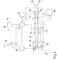
- FIG 2 shows a schematically simplified drive system 36 of the rail vehicle 10, not shown in detail Figure 1 .
- the components of this drive system 36 can in principle be distributed to any individual vehicles 11, 13 of the rail vehicle 10, but optionally combined in one of the railcars 13.
- all of the shown components of the drive system 36 can be connected to the control device 32 in order to transmit signals to it and / or to receive control signals from it. This also applies to the phase detection device 31 Figure 1 .
- the drive system 36 is electrically connected to the pantograph 30, which is also shown. Starting from the current collector 30, the electrical energy consumed is fed via a conventional high-voltage converter 40 and a conventional main switch 38 to a likewise conventional main transformer 42.
- the main switch 38 is set up in a known manner to separate the electrical connection between the current collector 30 and the main transformer 42 by selective opening.
- the high-voltage converter 40 can measure an applied voltage and / or a current flow that is applied to the main transformer 42 on the primary side.
- the high-voltage converter 40 is connected in a conventional manner between the current collector 20 and the main switch 38.
- the internal structure of the main transformer 42 is also shown greatly simplified.
- a magnetic core 48 and a primary winding 44 to which a primary voltage is applied are shown.
- Secondary windings 46 to which a (transformed) secondary voltage is applied are also shown.
- a main operating state of the main transformer 42 is assumed, in which electrical energy consumed via the current collector 30 is provided on the primary side and is converted into a secondary voltage for further use within the rail vehicle 10.
- a converter is also connected to each of the secondary windings 46, namely a first converter 50 and a further converter 52.
- Both converters 50, 52 which can also be referred to as line converters, can be operated either as rectifiers or as inverters and with a DC voltage intermediate circuit 51 connected.
- traction motors 56 are also connected, which can optionally be operated as a motor or generator.
- a motor converter 54 is connected between the DC voltage intermediate circuit 51 and the traction motors 56 and can in turn be operated either as a rectifier (for generator operation) or as an inverter (for motor operation).
- auxiliaries 58 are connected to the DC voltage intermediate circuit 51 via an on-board network 57. It is also possible as an alternative to the variant Figure 2 to supply the auxiliaries 58 with electrical energy via a separate secondary winding 46 and independently of the DC voltage intermediate circuit 51 to which the traction motors 56 are also connected. Even then, however, at least one further converter 52 would be present between this secondary winding 56 and the auxiliary units 58 and would be operated in the manner explained below.
- control device 32 and the memory device 34 are also entered again.
- exemplary communication connections are shown in dashed lines, which could also be provided via a vehicle bus.
- the control device 32 can in principle be set up to send control signals to each of the aforementioned converters 50, 52, 54 and optionally also the main switch 38 in order to operate these components in the manner described herein.
- the control device 32 can also receive measurement signals via the high-voltage converter 40 but also the detection device 31.
- the pantograph 20 When the pantograph 20 is in contact with a live contact wire section 18 and the main switch 38 is closed, as is generally the case while driving, the single-phase alternating voltage of the power supply 15 is applied to the main transformer 42 on the primary side (minus line losses not considered here).
- the main transformer 42 converts this voltage to a secondary-side voltage, which is typically lower.
- both of the converters 50, 52 are preferably operated as rectifiers and feed the DC voltage intermediate circuit 51 with electrical energy which is provided by the main transformer 42.
- the DC voltage intermediate circuit 51 feeds the motor converters 54, which generate AC voltage for the motor operation of the traction motors 56.
- the auxiliaries 58 are fed from the DC voltage intermediate circuit 51.
- the first converter 50 generates an alternating voltage when passing through the phase separation point 22, which is applied to the corresponding secondary winding 46 of the Main transformer 42 is applied. In principle, this would also be possible with the main switch 38 open. In this way, the magnetic field 42 is at least partially maintained in a defined manner and a primary-side voltage is also induced on the primary winding 44. As described, this prevents the main transformer 42 from significantly reducing its magnetization, which would lead to high inrush currents when it is re-entered into a live contact wire section 18. This can also dampen resonances.
- At least one of the traction motors 56 is operated as a generator and converts the traction energy of the rolling rail vehicle 10 into electrical energy (auxiliary braking operation).
- the assigned motor converter 54 is then operated as a rectifier.
- the application of the secondary-side alternating voltage makes it possible to set a phase position of the primary-side voltage. This is done in particular in such a way that it corresponds to a detected phase position in a bicycle section lying ahead or does not deviate therefrom beyond a maximum permissible phase difference.
- the secondary-side alternating voltage is generated in such a way that the primary-side voltage of the main transformer 42 is synchronized with the phase position of the voltage in the road section 18 ahead.
- the control device 32 receives signals from the phase detection device 31 relating to a detected phase position lying ahead and controls the first converter 50 accordingly.
- stored information on the phase positions in individual roadway sections 18 can be read out, for example, from the memory device 34 and the control device 32 can control the first converter 50 accordingly based thereon.
- the control device 32 can have a Carry out location recognition, for example using GPS signals or using position markings that can be automatically recognized by ATC systems. In this way, the current and / or the catenary section 18 lying ahead can then be identified and information on the phase position that is stored or retrievable for this catenary section 18 can be determined. Such information can be used for a plausibility check of the phase position, which is preferably detected without contact by the detection device 31.
- the further converter 52 is likewise not blocked, but rather operated as a rectifier and fed by the main transformer 42. More precisely, this further converter 52 converts a secondary voltage applied to the assigned secondary winding 46 and thus feeds the DC voltage intermediate circuit 51. The auxiliaries 58 can then continue to be operated via this, although due to the phase separation point 22 there is no sufficient energy supply from the power supply 15 .
- the auxiliaries 58 are thus supplied by means of an energy flow which runs via the first converter 50, the main transformer 42 and the further converter 52.
- the main transformer 42 is further stabilized and in particular resonances of the magnetic field that could occur due to the change in voltage 44 on the primary side are particularly effectively damped.
- any equalizing currents are dampened in the event of a lack of synchronization, and higher phase differences between the set phase position and the detected phase position can be accepted.
- one of the traction motors 56 as a motor in order to increase the electrical load that the main transformer 42 has to supply. This is particularly relevant when the electrical load is in the form of the auxiliaries 58 is below a desired minimum load. This can be checked by the control device 32 of the rail vehicle 10 and activated if necessary.
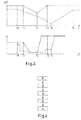
- the current collector 20 of the rail vehicle 10 reaches a phase separation point 22 at a point in time T1 and from then on the energy consumption from the power supply 15 is interrupted.
- the speed then begins to decrease, as the traction power is automatically reduced by the driver-autonomous ATC control.
- the end of the phase separation point 22 is reached and it is then started again to increase the traction power (likewise preferably via driver-autonomous ATC control).
- the rail vehicle 10 subsequently reaches the original speed again before the phase separation point 22 at the time T3.
- the time T1 and T2 the is also found below using the flow chart Figure 4 explained setting of the primary-side phase position instead. Since this is completed when the end of the phase separation point 22 is reached at time T3, the rail vehicle 10 can be accelerated again correspondingly quickly and delays are avoided.
- a state recognition which enables moving in and out of a phase separation point 22, can take place by means of the detection device 31 or else by measurements with the high-voltage converter 40 Figure 1 . These components can transmit corresponding signals to the control device 32, which then initiates the measures outlined.
- the control device 32 of the rail vehicle 10 can execute and / or provide any ATC functions described herein.
- the main switch 38 is opened again at time T0 before the phase separation point 22 is reached, and the traction power T is therefore started early.
- the traction power is then increased again only at time T4, this time T4 being well behind time T2 when the end of the phase separation point 22 is reached.
- the reason is a time delay, since the renewed presence of a voltage must be recognized, then the opened main switch 38 must first be closed again and the previously blocked converters 50, 52 can only then be switched on again. This also shows the dynamic loss of the rail vehicle 10 when passing a phase separation point 22 in comparison to the solution according to the invention.
- a step S1 the reaching of a phase separation point 22 is recognized, for example driver-autonomously by the control device 32 in cooperation with the detection device 31 and / or by measuring the applied voltage with the high-voltage converter 40.
- the relative distance of the detection device 31 to the pantograph 30 must be taken into account in order to computationally determine when the current collector 30 arrives at the phase separation point 22 as a result of the corresponding detection by the detection device 31 and taking into account the current vehicle speed.
- the main switch 38 is preferably, but not necessarily, kept closed. This can include that the control device 32 suppresses a corresponding opening signal output by other control devices or that in principle no corresponding opening signal generation takes place. Step S2 is therefore not necessarily associated with an action actually carried out.
- a phase position is detected with the detection device 31. Due to the positioning of the detection device 31 relative to the current collector 30, it can be assumed with sufficient certainty that the phase position of the current is determined in this case, which is applied to the separation point 22 following contact wire section 18 is applied. In addition, as expected, the detection device 31 within the phase separation point 22 would not determine any electrical properties other than zero, so that the presence of a detection signal in itself already confirms the measurement of the corresponding contact wire section 18.
- the first power converter 50 is then operated as an inverter (for example under control by the control device 32) and fed from the DC voltage intermediate circuit 51.
- the alternating voltage generated is applied to the main transformer 42 on the secondary side and results in a primary-side voltage which is generated in accordance with the phase position detected by the detection device 31. More precisely, the alternating voltage is generated in such a way that a phase position of the resulting voltage on the primary side is as synchronized as possible with a detected phase position of the contact wire section 18 lying ahead, i.e. H. matches.
- the high-voltage converter 40 which can still be used for measuring the primary-side voltage due to the main switch 38 being kept closed, to measure the voltage generated on the primary side and to measure the operation of the first converter 50 or that of it Adapt the generated alternating voltage appropriately. In this way, for example, the setting of a desired phase position of the primary voltage can be ensured.
- step S5 which can also be carried out before or at the same time as step S4, an electrical load is then applied to the main transformer 42 with the further converter 52 in the manner described above.
- a step S6 the exit from the phase separation point 22 is registered (for example again with the high-voltage converter 40).
- the first converter 50 is then operated again as a rectifier and the traction power T of the rail vehicle 10 is preferably run up autonomously by the driver.
- step S5. Because of the maintained magnetization of the main transformer 42, no significant inrush currents occur in step S5.
- the main transformer 42 can therefore be fully efficient again particularly early, which limits losses in driving dynamics, and protective shutdowns are avoided.
- losses of time that would be associated with opening and closing again are avoided.
- the main switch 38 is also less stressed by failing to open and close and experiences less wear.
Landscapes
- Engineering & Computer Science (AREA)
- Mechanical Engineering (AREA)
- Power Engineering (AREA)
- Transportation (AREA)
- Life Sciences & Earth Sciences (AREA)
- Sustainable Development (AREA)
- Sustainable Energy (AREA)
- Electric Propulsion And Braking For Vehicles (AREA)
- Current-Collector Devices For Electrically Propelled Vehicles (AREA)
- Train Traffic Observation, Control, And Security (AREA)
Applications Claiming Priority (1)
| Application Number | Priority Date | Filing Date | Title |
|---|---|---|---|
| DE102019210768.0A DE102019210768A1 (de) | 2019-07-19 | 2019-07-19 | Phasenlagendetektion beim Passieren von Trennstellen in einer Stromversorgung für Schienenfahrzeuge |
Publications (2)
| Publication Number | Publication Date |
|---|---|
| EP3766722A2 true EP3766722A2 (fr) | 2021-01-20 |
| EP3766722A3 EP3766722A3 (fr) | 2021-05-26 |
Family
ID=71670138
Family Applications (1)
| Application Number | Title | Priority Date | Filing Date |
|---|---|---|---|
| EP20186501.1A Pending EP3766722A3 (fr) | 2019-07-19 | 2020-07-17 | Détection de la position de phase lors du passage de points de déconnexion dans une alimentation en courant pour véhicules ferroviaires |
Country Status (3)
| Country | Link |
|---|---|
| EP (1) | EP3766722A3 (fr) |
| CN (1) | CN112238793B (fr) |
| DE (1) | DE102019210768A1 (fr) |
Cited By (1)
| Publication number | Priority date | Publication date | Assignee | Title |
|---|---|---|---|---|
| GB2603906A (en) * | 2021-02-17 | 2022-08-24 | Bombardier Transp Gmbh | Rail vehicle and method of operating a rail vehicle that comprises a plurality of current collectors |
Citations (1)
| Publication number | Priority date | Publication date | Assignee | Title |
|---|---|---|---|---|
| EP3182142A1 (fr) | 2015-12-15 | 2017-06-21 | Bombardier Transportation GmbH | Dispositif destiné à reconnaître un système de tension |
Family Cites Families (8)
| Publication number | Priority date | Publication date | Assignee | Title |
|---|---|---|---|---|
| JPS57170003A (en) * | 1981-04-10 | 1982-10-20 | Hitachi Ltd | Controlling method for electric motor vehicle |
| JPH08126114A (ja) * | 1994-10-19 | 1996-05-17 | Aisin Aw Co Ltd | モータ制御装置 |
| JP4537802B2 (ja) * | 2004-08-24 | 2010-09-08 | 株式会社東芝 | 電力変換装置 |
| US8836161B2 (en) * | 2009-03-13 | 2014-09-16 | Kabushiki Kaisha Toshiba | Rolling stock system and control method thereof |
| JP6003949B2 (ja) * | 2014-06-26 | 2016-10-05 | 株式会社明電舎 | 交流電気車の電源設備 |
| EP3056378A1 (fr) * | 2015-02-10 | 2016-08-17 | Schweizerische Bundesbahnen SBB | Procédé de surveillance et de commande d'un dispositif d'actionnement |
| GB2542432A (en) * | 2015-09-21 | 2017-03-22 | Bombardier Transp Gmbh | Inductively transferring electric energy to a vehicle using consecutive segments which are operated at the same time |
| CN109088534A (zh) * | 2018-08-27 | 2018-12-25 | 北京千驷驭电气有限公司 | 牵引变流器、混动车牵引变流器过分相控制系统及方法 |
-
2019
- 2019-07-19 DE DE102019210768.0A patent/DE102019210768A1/de active Pending
-
2020
- 2020-07-17 EP EP20186501.1A patent/EP3766722A3/fr active Pending
- 2020-07-20 CN CN202010697243.0A patent/CN112238793B/zh active Active
Patent Citations (1)
| Publication number | Priority date | Publication date | Assignee | Title |
|---|---|---|---|---|
| EP3182142A1 (fr) | 2015-12-15 | 2017-06-21 | Bombardier Transportation GmbH | Dispositif destiné à reconnaître un système de tension |
Cited By (2)
| Publication number | Priority date | Publication date | Assignee | Title |
|---|---|---|---|---|
| GB2603906A (en) * | 2021-02-17 | 2022-08-24 | Bombardier Transp Gmbh | Rail vehicle and method of operating a rail vehicle that comprises a plurality of current collectors |
| WO2022175336A1 (fr) * | 2021-02-17 | 2022-08-25 | Bombardier Transportation Gmbh | Véhicule ferroviaire et procédé de fonctionnement d'un véhicule ferroviaire comprenant une pluralité de collecteurs de courant |
Also Published As
| Publication number | Publication date |
|---|---|
| EP3766722A3 (fr) | 2021-05-26 |
| CN112238793A (zh) | 2021-01-19 |
| DE102019210768A1 (de) | 2021-01-21 |
| CN112238793B (zh) | 2024-12-20 |
Similar Documents
| Publication | Publication Date | Title |
|---|---|---|
| EP2941363B2 (fr) | Alimentation en énergie électrique de moteurs électriques de propulsion d'un véhicule ferroviaire à l'aide d'une pluralité de moteurs à combustion | |
| EP2870020B1 (fr) | Alimentation en énergie électrique de moteurs électriques de traction et d'auxiliaires électriques additionnels d'un véhicule ferroviaire | |
| DE102013207952A1 (de) | Vorrichtung zum Betreiben zumindest eines elektrischen Verbrauchers eines Schienenfahrzeugs | |
| EP2996898B1 (fr) | Unité d'entraînement pour la commande d'un moteur | |
| EP3766719B1 (fr) | Fonctionnement d'un véhicule ferroviaire lors du passage des points de déconnexion dans une alimentation en courant externe du véhicule | |
| EP1472112B1 (fr) | Vehicule pouvant fonctionner sur accumulateurs et procede pour faire fonctionner un tel vehicule | |
| EP3634803B1 (fr) | Source de puissance pour un vehicule ferroviare | |
| EP3828052B1 (fr) | Fonctionnement de véhicules ferroviaires permettant de limiter les pics de puissance dans une alimentation électrique | |
| DE102017105728A1 (de) | Vorrichtung zur Energieversorgung eines elektrischen Betriebsnetzes | |
| DE102008037661A1 (de) | Triebzug für teilweise oberleitungslosen Betrieb und Verfahren zu dessen Energiemanagement | |
| CH711843A1 (de) | Oberleitungsbus mit einem Trenntransformator in der Stromversorgung. | |
| DE102018209583A1 (de) | Verbund aus Fahrzeugen und Verfahren zum Speisen eines elektrischen Bordnetzwerks in einem solchen Verbund | |
| DE102019219032A1 (de) | Aufweckvorgang für elektrische Netze in einem Fahrzeug mit elektrischem Antriebsstrang | |
| EP3766722A2 (fr) | Détection de la position de phase lors du passage de points de déconnexion dans une alimentation en courant pour véhicules ferroviaires | |
| DE102013225815A1 (de) | Verfahren und Vorrichtung zum Betreiben einer unterbrechungsfreien Stromversorgung für Komponenten der Leit- und Sicherungstechnik | |
| EP3630571B1 (fr) | Système de transport à traction par câble et procédé pour faire fonctionner ce système | |
| EP2552727B1 (fr) | Onduleur pour une machine électrique et procédé pour faire fonctionner un onduleur pour une machine électrique | |
| WO2024146716A1 (fr) | Alimentation électrique pour un véhicule ferroviaire présentant une batterie de traction | |
| EP0207280B1 (fr) | Appareil d'alimentation en énergie pour une voiture de voyageurs avec freins à courants de Foucault | |
| CH714566B1 (de) | Oberleitungsbus mit einem Trenntransformator in der Stromversorgung. | |
| EP3798042B1 (fr) | Véhicule ferroviaire alimenté par batteries | |
| EP3581427A1 (fr) | Procédé de fonctionnement d'un véhicule à entraînement électrique et véhicule à entraînement électrique | |
| DE102024209332A1 (de) | Gleichstrom-Bordnetz eines Schienenfahrzeugs | |
| DE112023006126T5 (de) | Elektrowagen-steuersystem | |
| DE102024208144A1 (de) | Verfahren zum Lokalisieren eines Isolationsfehlers in einem Bordnetz eines Schienenfahrzeugs |
Legal Events
| Date | Code | Title | Description |
|---|---|---|---|
| PUAI | Public reference made under article 153(3) epc to a published international application that has entered the european phase |
Free format text: ORIGINAL CODE: 0009012 |
|
| STAA | Information on the status of an ep patent application or granted ep patent |
Free format text: STATUS: THE APPLICATION HAS BEEN PUBLISHED |
|
| AK | Designated contracting states |
Kind code of ref document: A2 Designated state(s): AL AT BE BG CH CY CZ DE DK EE ES FI FR GB GR HR HU IE IS IT LI LT LU LV MC MK MT NL NO PL PT RO RS SE SI SK SM TR |
|
| AX | Request for extension of the european patent |
Extension state: BA ME |
|
| PUAL | Search report despatched |
Free format text: ORIGINAL CODE: 0009013 |
|
| AK | Designated contracting states |
Kind code of ref document: A3 Designated state(s): AL AT BE BG CH CY CZ DE DK EE ES FI FR GB GR HR HU IE IS IT LI LT LU LV MC MK MT NL NO PL PT RO RS SE SI SK SM TR |
|
| RIC1 | Information provided on ipc code assigned before grant |
Ipc: B60L 9/08 20060101AFI20210419BHEP Ipc: B60L 50/53 20190101ALI20210419BHEP Ipc: B60L 5/00 20060101ALI20210419BHEP |
|
| STAA | Information on the status of an ep patent application or granted ep patent |
Free format text: STATUS: REQUEST FOR EXAMINATION WAS MADE |
|
| 17P | Request for examination filed |
Effective date: 20211122 |
|
| RBV | Designated contracting states (corrected) |
Designated state(s): AL AT BE BG CH CY CZ DE DK EE ES FI FR GB GR HR HU IE IS IT LI LT LU LV MC MK MT NL NO PL PT RO RS SE SI SK SM TR |
|
| STAA | Information on the status of an ep patent application or granted ep patent |
Free format text: STATUS: EXAMINATION IS IN PROGRESS |
|
| 17Q | First examination report despatched |
Effective date: 20230203 |
|
| RAP1 | Party data changed (applicant data changed or rights of an application transferred) |
Owner name: ALSTOM HOLDINGS |
|
| P01 | Opt-out of the competence of the unified patent court (upc) registered |
Effective date: 20230822 |