EP3766751A1 - Réservoir en plastique moulé renforcé - Google Patents
Réservoir en plastique moulé renforcé Download PDFInfo
- Publication number
- EP3766751A1 EP3766751A1 EP19186829.8A EP19186829A EP3766751A1 EP 3766751 A1 EP3766751 A1 EP 3766751A1 EP 19186829 A EP19186829 A EP 19186829A EP 3766751 A1 EP3766751 A1 EP 3766751A1
- Authority
- EP
- European Patent Office
- Prior art keywords
- tank
- patch
- equal
- bladder
- plastic
- Prior art date
- Legal status (The legal status is an assumption and is not a legal conclusion. Google has not performed a legal analysis and makes no representation as to the accuracy of the status listed.)
- Withdrawn
Links
- 239000002991 molded plastic Substances 0.000 title claims abstract description 6
- 239000000463 material Substances 0.000 claims abstract description 22
- 239000004033 plastic Substances 0.000 claims abstract description 22
- 229920003023 plastic Polymers 0.000 claims abstract description 22
- 239000012530 fluid Substances 0.000 claims abstract description 10
- 230000003014 reinforcing effect Effects 0.000 claims abstract description 6
- 238000004891 communication Methods 0.000 claims abstract description 5
- -1 polypropylene Polymers 0.000 claims description 13
- 239000000835 fiber Substances 0.000 claims description 11
- 239000004743 Polypropylene Substances 0.000 claims description 7
- 229920001155 polypropylene Polymers 0.000 claims description 7
- 239000002759 woven fabric Substances 0.000 claims description 6
- 239000004744 fabric Substances 0.000 claims description 5
- 239000004952 Polyamide Substances 0.000 claims description 4
- 239000000945 filler Substances 0.000 claims description 4
- 229920002647 polyamide Polymers 0.000 claims description 4
- 229920000728 polyester Polymers 0.000 claims description 4
- 229920000139 polyethylene terephthalate Polymers 0.000 claims description 4
- 239000005020 polyethylene terephthalate Substances 0.000 claims description 4
- 238000003466 welding Methods 0.000 claims description 4
- 229920000049 Carbon (fiber) Polymers 0.000 claims description 3
- 239000004698 Polyethylene Substances 0.000 claims description 3
- 239000004760 aramid Substances 0.000 claims description 3
- 229920003235 aromatic polyamide Polymers 0.000 claims description 3
- 239000011324 bead Substances 0.000 claims description 3
- 239000004917 carbon fiber Substances 0.000 claims description 3
- 229920000573 polyethylene Polymers 0.000 claims description 3
- 229920000642 polymer Polymers 0.000 claims description 3
- 230000002787 reinforcement Effects 0.000 abstract description 2
- 239000002994 raw material Substances 0.000 description 7
- 238000000034 method Methods 0.000 description 4
- 239000000243 solution Substances 0.000 description 4
- 238000007872 degassing Methods 0.000 description 3
- 238000001746 injection moulding Methods 0.000 description 2
- 238000004519 manufacturing process Methods 0.000 description 2
- 230000000052 comparative effect Effects 0.000 description 1
- 238000005336 cracking Methods 0.000 description 1
- 230000003247 decreasing effect Effects 0.000 description 1
- 239000003365 glass fiber Substances 0.000 description 1
- 238000002347 injection Methods 0.000 description 1
- 239000007924 injection Substances 0.000 description 1
- 238000000465 moulding Methods 0.000 description 1
- 230000002093 peripheral effect Effects 0.000 description 1
- 230000035699 permeability Effects 0.000 description 1
Images

Classifications
-
- B—PERFORMING OPERATIONS; TRANSPORTING
- B60—VEHICLES IN GENERAL
- B60T—VEHICLE BRAKE CONTROL SYSTEMS OR PARTS THEREOF; BRAKE CONTROL SYSTEMS OR PARTS THEREOF, IN GENERAL; ARRANGEMENT OF BRAKING ELEMENTS ON VEHICLES IN GENERAL; PORTABLE DEVICES FOR PREVENTING UNWANTED MOVEMENT OF VEHICLES; VEHICLE MODIFICATIONS TO FACILITATE COOLING OF BRAKES
- B60T11/00—Transmitting braking action from initiating means to ultimate brake actuator without power assistance or drive or where such assistance or drive is irrelevant
- B60T11/10—Transmitting braking action from initiating means to ultimate brake actuator without power assistance or drive or where such assistance or drive is irrelevant transmitting by fluid means, e.g. hydraulic
- B60T11/26—Reservoirs
Definitions
- the present invention concerns a tank, in particular for a vehicle such as an automotive vehicle, this tank being made of plastic and being manufactured by injection molding.
- Tanks of vehicle can be made by injection molding. This is the case for instance of a degassing tank or a brake tank.
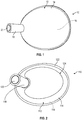
- a tank 10 is shown in figure 1 and includes a single-piece body 12 made of a molded plastic material. This body 12 comprises a bladder 14 defining an internal fluid cavity 16 and a protruding neck 18 defining a fluid port 20 in fluidic communication with the cavity 16.
- Such a tank is subjected to high internal pressure and high temperature in operation.
- a degassing tank must resist to internal pressure of about 140kPa and temperature up to 135°C.
- the plastic material of the tank should therefore be selected to withstand such conditions.
- the material of the tank should also be sufficiently flexible so as to allow resultant deformations of the tank in operation in order to avoid any interference with surrounding parts.
- a tank is typically shaped and dimensioned according to the stress limit of its raw material.
- the main stressed area and the biggest deformations are often located at the top and / or the bottom of the tank.
- solutions to this technical problem consist in providing stiffening ribs on or in the bladder, adjusting curvature radii of the bladder and of the linking area between the neck and the bladder, increasing the thickness of the bladder, introducing fillers into the raw material, such as glass fibers, etc.
- the present invention concerns a tank, in particular for a vehicle, comprising a single-piece body made of a molded plastic material, said body comprising a bladder defining an internal fluid cavity and a protruding neck defining a fluid port in fluidic communication with said cavity, characterized in that it further includes at least one reinforcing plastic patch integrated into the molded material.
- the purpose of this invention is to optimize the mechanical resistance / deformation of the tank without changing its shape, internal volume, and weight. This aim is achieved by the reinforced patch which is integrated into the material of the tank. Both the raw materials of the tank and the patch are plastic materials.
- Said patch is preferably located in an area of the bladder where such local reinforcement is needed.
- said patch extends at least in part about said neck.
- the tank according to the invention may comprise one or more of the following features, taken alone from each other or in combination with each other:
- FIG 1 illustrates the prior art and has already been described.
- FIG. 2 illustrates a tank 100 according to an embodiment of the invention.
- the tank 100 is a vehicle tank and in particular a degassing tanks in the example shown.
- the tank 100 includes a single-piece body 112 made of a molded plastic material.
- This body 112 comprises a bladder 114 defining an internal fluid cavity 116 and a protruding neck 118 defining a fluid port 120 in fluidic communication with the cavity 116.
- the body 112 of the tank 120 may be made of an upper molded shell and a lower molded shell which are welded together and linked to one another by a welding bead 122.
- the lower shell is not visible and the upper shell includes the neck 118.
- the tank 100 further includes a reinforcing plastic patch 124 integrated into the molded material.
- the plastic material of the tank is selected among polypropylene and polyethylene, and a combination thereof. Said plastic material is devoid of any filler outside the area occupied by the patch 124.
- the patch 124 is configured to reinforce the tank in particular in the area where high stresses occurred in operation.
- One such area is the area surrounding the neck 118.
- the patch 124 extends therefore at least in part about said neck 118.
- the patch 124 is made of plastic and preferably of plastic fibers.
- the patch 124 may have any shape and is preferably in the form of a fabric (woven or unwoven) and more preferably of a woven fabric because such woven fabric has better mechanical properties than unwoven fabric.
- Figure 3 shows an example of shape for the patch and Figure 4 shows a schematic example of a woven fabric of plastic or carbon fibers.
- the patch 124 may have a peripheral edge 126 having curved portions 126a, 126b, 126c, 126d, etc.
- the patch 124 includes a curved portions 126a extending about 180° and intended to extend about the neck 118.
- the patch 124 may have a curved portion 126b diametrically opposed to the portion 124a with respect to a center C of the patch 120. Between both portions 126a, 126b, the patch 124 may have lateral curved portions 126c, 126d.
- the concavity of the portions 126b, 126c, 126d are oriented towards the center C while the concavity of the portion 126a is oriented away from the center.
- the plastic fibers are made of at least one polymer selected from the group consisting of polyester, polyamide, polypropylene, polyethylene terephthalate, aramid,
- plastic material that might be used as patch 124 or to form such patch are:
- the fibers have a diameter d1 lower than or equal to 500 ⁇ m, and preferably lower than or equal to 250 ⁇ m ( Figure 4 ).
- the mesh opening d2 of the fabric is for instance lower than or equal to 1000 ⁇ m, preferably lower than or equal to 800 ⁇ m, and more preferably lower than or equal to 500 ⁇ m ( Figure 4 ).
- Thickness of the patch lower than or equal to 1000 ⁇ m, preferably lower than or equal to 500 ⁇ m Weight of the patch lower than or equal to 500g/m 2 , preferably lower than or equal to 200g/m 2
- the patch 124 may be colored and/or printed.
- the material of the tank would be transparent or slightly transparent, and for instance of a light white color, it might be possible to use a patch of another color such as red, blue or green so that a technician might easily visually identify whether the tank is reinforced or not.
- the patch may further be printed to provide information to the technician for instance.
- the tank and bladder area may have a thickness which is between 1.5 mm and 4 mm.
- the purpose of this invention is to optimize the mechanical resistance / deformation of the tank without changing its shape, internal volume, and weight. Its raw material is not even changed so as to keep the ability of the bladder to be welded as described above.
- the tank according to the invention may be manufactured by a method including the following steps:
Landscapes
- Engineering & Computer Science (AREA)
- Transportation (AREA)
- Mechanical Engineering (AREA)
- Laminated Bodies (AREA)
Priority Applications (1)
| Application Number | Priority Date | Filing Date | Title |
|---|---|---|---|
| EP19186829.8A EP3766751A1 (fr) | 2019-07-17 | 2019-07-17 | Réservoir en plastique moulé renforcé |
Applications Claiming Priority (1)
| Application Number | Priority Date | Filing Date | Title |
|---|---|---|---|
| EP19186829.8A EP3766751A1 (fr) | 2019-07-17 | 2019-07-17 | Réservoir en plastique moulé renforcé |
Publications (1)
| Publication Number | Publication Date |
|---|---|
| EP3766751A1 true EP3766751A1 (fr) | 2021-01-20 |
Family
ID=67437867
Family Applications (1)
| Application Number | Title | Priority Date | Filing Date |
|---|---|---|---|
| EP19186829.8A Withdrawn EP3766751A1 (fr) | 2019-07-17 | 2019-07-17 | Réservoir en plastique moulé renforcé |
Country Status (1)
| Country | Link |
|---|---|
| EP (1) | EP3766751A1 (fr) |
Citations (3)
| Publication number | Priority date | Publication date | Assignee | Title |
|---|---|---|---|---|
| US5020687A (en) * | 1990-02-12 | 1991-06-04 | Solvay Automotive, Inc. | Fabric reinforcement for plastic fuel tanks |
| US5885515A (en) * | 1997-03-06 | 1999-03-23 | Lear Corporation | Blow molding process |
| US20100316310A1 (en) * | 2009-06-12 | 2010-12-16 | Material Engineering and Technical Support Services Corporation | Containment Systems |
-
2019
- 2019-07-17 EP EP19186829.8A patent/EP3766751A1/fr not_active Withdrawn
Patent Citations (4)
| Publication number | Priority date | Publication date | Assignee | Title |
|---|---|---|---|---|
| US5020687A (en) * | 1990-02-12 | 1991-06-04 | Solvay Automotive, Inc. | Fabric reinforcement for plastic fuel tanks |
| US5885515A (en) * | 1997-03-06 | 1999-03-23 | Lear Corporation | Blow molding process |
| US5885515C1 (en) * | 1997-03-06 | 2002-01-15 | Lear Corp | Blow molding process |
| US20100316310A1 (en) * | 2009-06-12 | 2010-12-16 | Material Engineering and Technical Support Services Corporation | Containment Systems |
Similar Documents
| Publication | Publication Date | Title |
|---|---|---|
| EP2399761A1 (fr) | Pneu | |
| CN106696315B (zh) | 智能监控三维复合材料耐压气瓶及其制备方法 | |
| EP2756977A1 (fr) | Réservoir de carburant en plastique avec résistance au fluage améliorée et procédé pour la fabrication de celui-ci | |
| BRPI0714151A2 (pt) | mÉtodo para produzir um componente compàsito de fibra para indéstria aeroespacial | |
| EP3448707B1 (fr) | Renforcement de réservoir avec déflecteur intégré | |
| CN111186264A (zh) | 轮胎 | |
| CN102180425A (zh) | 在压力机中由热硫化网状橡胶材料制成的提升袋及其制作方法 | |
| EP3766751A1 (fr) | Réservoir en plastique moulé renforcé | |
| US4435240A (en) | Fabric-reinforced, flexible-walled container and method of making said container | |
| CN113165448A (zh) | 多气室轮胎 | |
| US20070068199A1 (en) | Suds container for a washing machine and method for making a suds container | |
| CN105829156A (zh) | 具有增强件的工作液容器 | |
| US20100212815A1 (en) | Pressure vessel | |
| US20210276284A1 (en) | Method for producing a pressure accumulator | |
| EP2682280A1 (fr) | Pneu | |
| KR101069077B1 (ko) | 프리 어셈블리 단일 반제품을 갖는 공기입 타이어 | |
| JP5647811B2 (ja) | ダイヤフラム弁用ダイヤフラム及びその製造方法 | |
| JP4323131B2 (ja) | 空気入りタイヤ | |
| GB2088281A (en) | Fabric-reinforced Composite Material for a Flexible-walled Container and Method of Making Said Container | |
| CN101104372A (zh) | 具有整体帘布加强层的轮胎 | |
| EP3181340A1 (fr) | Pneumatique ayant un composant d'étanchéité | |
| US20190016290A1 (en) | Passenger side airbag housing, manufacturing method therefor, and passenger side airbag for vehicle | |
| KR101070965B1 (ko) | 연장된 림플랜지를 갖는 공기입 타이어 | |
| US3016320A (en) | Method of making pneumatic tires | |
| CN1915713A (zh) | 带整体式安全气囊盖的仪表面板 |
Legal Events
| Date | Code | Title | Description |
|---|---|---|---|
| PUAI | Public reference made under article 153(3) epc to a published international application that has entered the european phase |
Free format text: ORIGINAL CODE: 0009012 |
|
| STAA | Information on the status of an ep patent application or granted ep patent |
Free format text: STATUS: THE APPLICATION HAS BEEN PUBLISHED |
|
| AK | Designated contracting states |
Kind code of ref document: A1 Designated state(s): AL AT BE BG CH CY CZ DE DK EE ES FI FR GB GR HR HU IE IS IT LI LT LU LV MC MK MT NL NO PL PT RO RS SE SI SK SM TR |
|
| AX | Request for extension of the european patent |
Extension state: BA ME |
|
| STAA | Information on the status of an ep patent application or granted ep patent |
Free format text: STATUS: THE APPLICATION IS DEEMED TO BE WITHDRAWN |
|
| 18D | Application deemed to be withdrawn |
Effective date: 20210721 |