EP3766788A1 - Vorrichtung zur bereitstellung von flüssigkeit oder energie für ein flugzeug - Google Patents
Vorrichtung zur bereitstellung von flüssigkeit oder energie für ein flugzeug Download PDFInfo
- Publication number
- EP3766788A1 EP3766788A1 EP19382606.2A EP19382606A EP3766788A1 EP 3766788 A1 EP3766788 A1 EP 3766788A1 EP 19382606 A EP19382606 A EP 19382606A EP 3766788 A1 EP3766788 A1 EP 3766788A1
- Authority
- EP
- European Patent Office
- Prior art keywords
- aircraft
- duct
- docking event
- situation
- preparation
- Prior art date
- Legal status (The legal status is an assumption and is not a legal conclusion. Google has not performed a legal analysis and makes no representation as to the accuracy of the status listed.)
- Withdrawn
Links
Images



Classifications
-
- B—PERFORMING OPERATIONS; TRANSPORTING
- B64—AIRCRAFT; AVIATION; COSMONAUTICS
- B64F—GROUND OR AIRCRAFT-CARRIER-DECK INSTALLATIONS SPECIALLY ADAPTED FOR USE IN CONNECTION WITH AIRCRAFT; DESIGNING, MANUFACTURING, ASSEMBLING, CLEANING, MAINTAINING OR REPAIRING AIRCRAFT, NOT OTHERWISE PROVIDED FOR; HANDLING, TRANSPORTING, TESTING OR INSPECTING AIRCRAFT COMPONENTS, NOT OTHERWISE PROVIDED FOR
- B64F1/00—Ground or aircraft-carrier-deck installations
- B64F1/30—Ground or aircraft-carrier-deck installations for embarking or disembarking passengers
- B64F1/305—Bridges extending between terminal building and aircraft, e.g. telescopic, vertically adjustable
-
- B—PERFORMING OPERATIONS; TRANSPORTING
- B64—AIRCRAFT; AVIATION; COSMONAUTICS
- B64F—GROUND OR AIRCRAFT-CARRIER-DECK INSTALLATIONS SPECIALLY ADAPTED FOR USE IN CONNECTION WITH AIRCRAFT; DESIGNING, MANUFACTURING, ASSEMBLING, CLEANING, MAINTAINING OR REPAIRING AIRCRAFT, NOT OTHERWISE PROVIDED FOR; HANDLING, TRANSPORTING, TESTING OR INSPECTING AIRCRAFT COMPONENTS, NOT OTHERWISE PROVIDED FOR
- B64F1/00—Ground or aircraft-carrier-deck installations
- B64F1/36—Other airport installations
- B64F1/362—Installations for supplying conditioned air to parked aircraft
Definitions
- the invention refers to a device for providing fluid, in particular conditioned air, or energy, in particular electric energy, to an aircraft, when the aircraft is located at an airport stand.
- the device is installed at the airport stand.
- the device is part of a passenger boarding bridge.
- the main idea is to provide some of the functionalities in dependency of the docking event.
- the docking even it is in particular characterized by the type of aircraft which is located at the stand.
- the device is then used to establish a connection between a stationary supplier, in particular a supplier of air or a supplier of energy. Establishing a dependency between the docking situation and the functionality can increase the ergonomics and efficiency of the device.
- the docking event is characterized by a certain height parameter.
- the height parameter may be the height of the door of the aircraft to which the device may be attached. Based on said height the height of the device may dependent. So in case the height is very high it may be difficult for the user to reach the device.
- the duct is extracted into a preparation length.
- the preparation length is dependent from the docking event.
- a handle of the duct is located at a preparation height over ground of max. 2,0m.
- the handle may not be in reach for the user.
- the handle of the duct is located at a height of more than the preparation height, in particular more than 2,0m.
- connection length is dependent from the docking event.
- connection length is long enough so that the duct can be attached to the aircraft.
- the optimum length is automatically calculated on the basis of the provided information. Extracting the duct merely with the essential required length reduces wear to the duct.
- connection length varies from a connection length (L3) of a second docking event. That means that the length to which the duct is extracted can vary during the several docking events. If a bigger aircraft is to be handled at the gate the required extraction length will likely be greater than in a docking event when a smaller aircraft is to be handled.
- the information of the actual docking event is received from or provided by an external data source, in particular by a VDGS system and/or a flight database, in particular the information of the actual docking event comprises an information related type to the aircraft type.
- the external data source may be outside of the device and/or outside of the passenger boarding bridge.
- the invention refers also to a passenger boarding bridge, have a device as describe above.
- the device may be located on an underside of a tunnel of the passenger boarding bridge.
- the passenger boarding bridge can be connected to at least two doors of the aircraft.
- the actual docking event is characterized by a selection, to which of the at least two doors the passenger boarding bridge is to be connected. Since the bridge can be connected to different doors of the aircraft the information is relevant to which of the doors the PBB will be docked in the actual docking event. Based on this information the operation parameters of the device can be adapted accordingly.
- a passenger boarding bridge can comprise more than one, at least two or three of such devices.
- the plurality of devices constitute a group of devices, in particular one device for providing air, another device for providing energy, in particular electricity.
- PBBs may be installed, in particular to be docked to the same aircraft.
- an information about the docking event may provided; based on the provided information automatically at least one device is selected out of the group of the devices, which is to be used during handling the aircraft.
- Another one of the devices may be non-selected, which means that this device will not be used in the actual docking event.
- the selected device is automatically at least allowed and/or transferred from a retracted situation into a preparation situation and/or into a extracted situation; in another embodiment it is prohibiting that a non-selected device is transferred from out or out of the retracted situation.
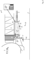
- Figures 1 to 3 show an aircraft 1 during a usual situation located at a gate of an airport.
- the aircraft 1 is standing with its wheels on the airport apron ground 3.
- a passenger boarding bridge 2 is connected to the aircraft 1.
- Attached to the passenger boarding bridge 2 is an inventive device 10 adapted to provide conditioned air and/or electricity to the aircraft 1
- the device 10 comprises a duct 14, which can be an air hose or an electric conduit.
- the duct having a first end 15 with a connection member 17, in particular a nozzle or an electric connector.
- the connection member 17 is adapted to be attached to the aircraft 1 as shown in figure 3 .
- the duct 14 having a second end 16, attached a supply duct or the like, e.g. a supply tube 4.
- the device 10 comprises a housing 11 as a storage for accommodating the duct 14 during a retracted situation as shown in figure 1 .
- the storage 11 may be a cable drum or the like.
- Attached at the storage is 11 a drive 18 is installed for releasing the duct 14 in an outward direction 0 or to pull the duct 14 in an inward direction I.
- the drive 18 is located in the near of an outlet end 12, so the sections of the hose 14, which are released by the drive 18, are released from the outlet end 12 away from the storage.
- An inlet end 13 is opposite to the outlet end 12; a supply tube 4 may be attached to the inlet end 13.
- a control unit 19 is adapted to control the operation of the drive 18.
- the device is attached to an underside of a tunnel 7 of the PBB.
- the tunnel 7 can be lifted or lowered so as to be aligned to the height of a door of an aircraft, which leads to a change in the height of the housing 11 of the device in the same manner.
- the duct is out of reach for an operator. So before the operator can grab the duct the duct has to be extracted for a certain amount, but not too far because the duct should not touch the ground during the preparation situation.
- the duct 14 is fully retracted at a first length L1, which is about 0m or several decimeters.
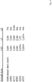
- the housing outlet 12 is located at a height of H1. It is to be considered that the height of the aircrafts doors over ground varies between different aircraft types. So when the PBB is docked with respect to an aircraft door of different types of aircrafts, the height H1 varies as shown in table of figure 4 .
- a user HMI 21 is attached to the device 10 for providing an indication to a user whether the device is to be used during the present docking event.
- the user HMI can be a simple light, an acoustic indicator or any other suitable means.
- FIG. 3 shows a connection situation.
- the duct is extracted at a connection length L3. Extracted does necessarily mean "fully extracted as far as possible”. Rather here the duct is extracted as far as required in the actual docking event, in particular by the type of aircraft which is currently located at the stand. It is apparent, that the location of the connection points at the aircraft with respect to the aircraft door varies between the different aircraft types. Consequently some aircrafts require a larger connection length L3 than other aircrafts.
- the control unit determines the connection length L3 based on the docking event and controls the drive to extract the duct according to the determined connection length L3. So in a particular embodiment there is no need for the operator at the ground to control the extraction of the duct into the connection length L3.
- FIG 2 shows the device in a preparation situation.
- the duct 14 is extracted to a preparation length L2.
- the height H2 of a handle 20, which may be part of the connection member, over ground is H2, wherein H2 is about 1,5m.
- H2 is about 1,5m.
- the duct is in a precondition to be grabbed by a gate operator; subsequently the operator connects the grabbed duct to the aircraft as shown in figure 3 .
- the duct does not touch the ground.
- the control unit determines the preparation length L2 based on the docking event and controls the drive to extract the duct according to the determined preparation length L2. So there is no need for the operator at the ground to control the extraction of the duct into the preparation length.
- VDGS e.g. disclosed in EP 2 660 152 A2
- the control unit 19 of the device can provide data of the aircraft type, which located at the stand.
- the control unit may have access to a database which comprises data as shown in figure 4 . By providing this amount of data the control unit 19 is set into a condition to extract the duct in the preparation situation and the connection situation as described.
- Some airport stands are provided with more than one passenger boarding bridge (PBB).
- An exemplary stand is provided with a first PBB1 and a second PBB2.
- the first PBB1 is provided with one inventive device 10 for providing air to the aircraft (climate1) and with two inventive devices 10 for providing electricity to the aircraft (electric1, electric2).
- the first PBB1 is docked to the first left door L1 (counted from the front of the aircraft) and the second PBB2 is docked to the second left door L2.
- the devices 10 “climate1”, “climate 2", electric1, and electric 2 are to be connected to the aircraft.
- the device “electric 2 will not be used.
- the user HMI 21 is also visible in the table. In case the device is to be used the light is on; otherwise the light is off.
Landscapes
- Engineering & Computer Science (AREA)
- Mechanical Engineering (AREA)
- Aviation & Aerospace Engineering (AREA)
- Architecture (AREA)
- Civil Engineering (AREA)
- Structural Engineering (AREA)
- Traffic Control Systems (AREA)
- Power-Operated Mechanisms For Wings (AREA)
Priority Applications (2)
| Application Number | Priority Date | Filing Date | Title |
|---|---|---|---|
| EP19382606.2A EP3766788A1 (de) | 2019-07-17 | 2019-07-17 | Vorrichtung zur bereitstellung von flüssigkeit oder energie für ein flugzeug |
| PCT/EP2020/062823 WO2021008753A1 (en) | 2019-07-17 | 2020-05-08 | A device adapted to provide a fluid or energy to an aircraft |
Applications Claiming Priority (1)
| Application Number | Priority Date | Filing Date | Title |
|---|---|---|---|
| EP19382606.2A EP3766788A1 (de) | 2019-07-17 | 2019-07-17 | Vorrichtung zur bereitstellung von flüssigkeit oder energie für ein flugzeug |
Publications (1)
| Publication Number | Publication Date |
|---|---|
| EP3766788A1 true EP3766788A1 (de) | 2021-01-20 |
Family
ID=67480126
Family Applications (1)
| Application Number | Title | Priority Date | Filing Date |
|---|---|---|---|
| EP19382606.2A Withdrawn EP3766788A1 (de) | 2019-07-17 | 2019-07-17 | Vorrichtung zur bereitstellung von flüssigkeit oder energie für ein flugzeug |
Country Status (2)
| Country | Link |
|---|---|
| EP (1) | EP3766788A1 (de) |
| WO (1) | WO2021008753A1 (de) |
Citations (7)
| Publication number | Priority date | Publication date | Assignee | Title |
|---|---|---|---|---|
| US20020195156A1 (en) | 2001-03-05 | 2002-12-26 | Bombardi Harry G. | Apparatus and a method for supplying conditioned air to an aircraft |
| US20090197516A1 (en) | 2008-02-02 | 2009-08-06 | Wright Joe W | Hose Management System for Supplying Conditioned Air to an Aircraft |
| ES2331983A1 (es) * | 2007-06-04 | 2010-01-21 | Bienvenido Peña Haro | Recogedor de mangueras de aire acondicionado. |
| EP2660152A2 (de) | 2012-04-30 | 2013-11-06 | Fmt International Trade Ab | Verfahren zur Identifizierung eines Flugzeugs in Verbindung mit dem Parken des Flugzeugs an einem Stand |
| WO2014108590A2 (es) | 2013-01-11 | 2014-07-17 | Thyssenkrupp Airport Services, S.L. | Dispositivo para la extracción y recogida de mangueras de aire acondicionado |
| EP3385172A1 (de) * | 2017-04-05 | 2018-10-10 | Thyssenkrupp Airport Systems, S.A. | Vorrichtung zur bereitstellung von klimatisierter luft in einem flugzeug |
| US10343788B2 (en) * | 2017-09-26 | 2019-07-09 | The Boeing Company | Telescoping refueling boom control systems and methods |
-
2019
- 2019-07-17 EP EP19382606.2A patent/EP3766788A1/de not_active Withdrawn
-
2020
- 2020-05-08 WO PCT/EP2020/062823 patent/WO2021008753A1/en not_active Ceased
Patent Citations (7)
| Publication number | Priority date | Publication date | Assignee | Title |
|---|---|---|---|---|
| US20020195156A1 (en) | 2001-03-05 | 2002-12-26 | Bombardi Harry G. | Apparatus and a method for supplying conditioned air to an aircraft |
| ES2331983A1 (es) * | 2007-06-04 | 2010-01-21 | Bienvenido Peña Haro | Recogedor de mangueras de aire acondicionado. |
| US20090197516A1 (en) | 2008-02-02 | 2009-08-06 | Wright Joe W | Hose Management System for Supplying Conditioned Air to an Aircraft |
| EP2660152A2 (de) | 2012-04-30 | 2013-11-06 | Fmt International Trade Ab | Verfahren zur Identifizierung eines Flugzeugs in Verbindung mit dem Parken des Flugzeugs an einem Stand |
| WO2014108590A2 (es) | 2013-01-11 | 2014-07-17 | Thyssenkrupp Airport Services, S.L. | Dispositivo para la extracción y recogida de mangueras de aire acondicionado |
| EP3385172A1 (de) * | 2017-04-05 | 2018-10-10 | Thyssenkrupp Airport Systems, S.A. | Vorrichtung zur bereitstellung von klimatisierter luft in einem flugzeug |
| US10343788B2 (en) * | 2017-09-26 | 2019-07-09 | The Boeing Company | Telescoping refueling boom control systems and methods |
Also Published As
| Publication number | Publication date |
|---|---|
| WO2021008753A1 (en) | 2021-01-21 |
Similar Documents
| Publication | Publication Date | Title |
|---|---|---|
| US7651052B2 (en) | Device for supplying electricity and air to an airplane on the ground | |
| EP2009263B1 (de) | Tangentiale Anti-Wirbel-Luftzufuhr | |
| CN102333699B (zh) | 用于集成在飞机系统内的发电系统 | |
| CN100500510C (zh) | 用于控制飞行器襟翼和阻流板的系统和方法 | |
| US8302902B2 (en) | Method and apparatus for operating an aircraft landing system | |
| US9266605B2 (en) | Aircraft having a vertical lift system | |
| JP2010540305A (ja) | 航空機の高揚力制御装置 | |
| WO2008042162A3 (en) | Air-vehicle augmented kinesthetic control system | |
| EP1327581A3 (de) | Verfahren und Vorrichtung zur Steuerung von Strömungen um Flugzeuge | |
| CN112173131A (zh) | 供应加压空气的安装件和方法、涡轮风扇发动机及飞行器 | |
| US20070051852A1 (en) | Operational ground support system having automated primary servicing | |
| CN101920782B (zh) | 用于装配有机电制动器的飞行器的制动系统构造 | |
| EP1700784B1 (de) | Betankungsmast mit mehreren Anschlüssen sowie Betankungsverfahren mit Hilfe dieses Masts | |
| CN101784972B (zh) | 控制一涡轮喷气发动机的推力反向器整流罩的至少一致动器的系统 | |
| US10618661B2 (en) | On-board removable container for cooling cargo materials and equipment in aircraft | |
| CN110949659A (zh) | 一种后缘襟翼控制方法 | |
| EP2690019A2 (de) | Betankungsauslegertrennungssystem | |
| WO2021008753A1 (en) | A device adapted to provide a fluid or energy to an aircraft | |
| CN105083571A (zh) | 一种可转动桁杆式直升机空中受油装置 | |
| CN107957732A (zh) | 无人机自动降落辅助引导系统 | |
| CN110282048A (zh) | 一种多用途无人机拖车系统 | |
| EP2876052A1 (de) | Luftbetankungssystem mit Betankungsschlauch und -korb mit einer aktiven Kraftstoffdrucksteuerung | |
| CN108983874A (zh) | 一种便于组装的工业平板电脑 | |
| CN111661315B (zh) | 无人机起落架自主放下管理方法及控制系统 | |
| US6698051B2 (en) | Automatically retracting passenger loading bridge |
Legal Events
| Date | Code | Title | Description |
|---|---|---|---|
| PUAI | Public reference made under article 153(3) epc to a published international application that has entered the european phase |
Free format text: ORIGINAL CODE: 0009012 |
|
| STAA | Information on the status of an ep patent application or granted ep patent |
Free format text: STATUS: THE APPLICATION HAS BEEN PUBLISHED |
|
| AK | Designated contracting states |
Kind code of ref document: A1 Designated state(s): AL AT BE BG CH CY CZ DE DK EE ES FI FR GB GR HR HU IE IS IT LI LT LU LV MC MK MT NL NO PL PT RO RS SE SI SK SM TR |
|
| AX | Request for extension of the european patent |
Extension state: BA ME |
|
| STAA | Information on the status of an ep patent application or granted ep patent |
Free format text: STATUS: REQUEST FOR EXAMINATION WAS MADE |
|
| 17P | Request for examination filed |
Effective date: 20210707 |
|
| RBV | Designated contracting states (corrected) |
Designated state(s): AL AT BE BG CH CY CZ DE DK EE ES FI FR GB GR HR HU IE IS IT LI LT LU LV MC MK MT NL NO PL PT RO RS SE SI SK SM TR |
|
| RIC1 | Information provided on ipc code assigned before grant |
Ipc: B64F 1/305 20060101ALN20220331BHEP Ipc: B64F 1/36 20170101AFI20220331BHEP |
|
| RIC1 | Information provided on ipc code assigned before grant |
Ipc: B64F 1/305 20060101ALN20220404BHEP Ipc: B64F 1/36 20170101AFI20220404BHEP |
|
| GRAP | Despatch of communication of intention to grant a patent |
Free format text: ORIGINAL CODE: EPIDOSNIGR1 |
|
| STAA | Information on the status of an ep patent application or granted ep patent |
Free format text: STATUS: GRANT OF PATENT IS INTENDED |
|
| INTG | Intention to grant announced |
Effective date: 20220513 |
|
| STAA | Information on the status of an ep patent application or granted ep patent |
Free format text: STATUS: THE APPLICATION IS DEEMED TO BE WITHDRAWN |
|
| 18D | Application deemed to be withdrawn |
Effective date: 20220924 |