EP3767064B1 - Hochwasserbarriere - Google Patents
Hochwasserbarriere Download PDFInfo
- Publication number
- EP3767064B1 EP3767064B1 EP20185944.4A EP20185944A EP3767064B1 EP 3767064 B1 EP3767064 B1 EP 3767064B1 EP 20185944 A EP20185944 A EP 20185944A EP 3767064 B1 EP3767064 B1 EP 3767064B1
- Authority
- EP
- European Patent Office
- Prior art keywords
- flood barrier
- floor
- flood
- edge
- head piece
- Prior art date
- Legal status (The legal status is an assumption and is not a legal conclusion. Google has not performed a legal analysis and makes no representation as to the accuracy of the status listed.)
- Active
Links
Images


Classifications
-
- E—FIXED CONSTRUCTIONS
- E06—DOORS, WINDOWS, SHUTTERS, OR ROLLER BLINDS IN GENERAL; LADDERS
- E06B—FIXED OR MOVABLE CLOSURES FOR OPENINGS IN BUILDINGS, VEHICLES, FENCES OR LIKE ENCLOSURES IN GENERAL, e.g. DOORS, WINDOWS, BLINDS, GATES
- E06B9/00—Screening or protective devices for wall or similar openings, with or without operating or securing mechanisms; Closures of similar construction
- E06B9/02—Shutters, movable grilles, or other safety closing devices, e.g. against burglary
-
- E—FIXED CONSTRUCTIONS
- E06—DOORS, WINDOWS, SHUTTERS, OR ROLLER BLINDS IN GENERAL; LADDERS
- E06B—FIXED OR MOVABLE CLOSURES FOR OPENINGS IN BUILDINGS, VEHICLES, FENCES OR LIKE ENCLOSURES IN GENERAL, e.g. DOORS, WINDOWS, BLINDS, GATES
- E06B9/00—Screening or protective devices for wall or similar openings, with or without operating or securing mechanisms; Closures of similar construction
- E06B2009/007—Flood panels
Definitions
- the present invention relates to an anti-flood device.
- the present invention regards an anti-flood device prearranged for isolating buildings from water.
- the present invention regards an anti-flood device prearranged for isolating buildings from water using at least one mobile flood barrier.
- the openings at ground-floor level for doors or windows are normally provided with guides for mobile flood barriers, usually having a rectangular shape, which are normally stored in the cellar or basement, and, in the case of danger of flooding, are positioned between the guides.
- guides for mobile flood barriers usually having a rectangular shape, which are normally stored in the cellar or basement, and, in the case of danger of flooding, are positioned between the guides.
- hydraulic sealing is further improved by the use of pressure members that force contact between the sides of the flood barrier and the guides and between the base of the flood barrier and the floor portion.
- the simple force of gravity is not sufficient to hold the flood barrier in place downwards.
- the guides are equipped with brackets, and so also the flood barrier, which as far as possible are set facing one another and possibly in mutual contact when the flood barrier is installed; the brackets are connected through via padlocks so as to prevent relative deviation due to floating of the flood barrier between the guides or limit any transverse play and relative seepage that are even so present.
- wedge-shaped members that are interposed in the gaps between the sides of the flood barrier and the guides so as to minimize the risk of front seepage, and devices are used designed to exert pressure downwards on the flood barrier to limit the risk of seepage between the base of the flood barrier and the floor.
- the present invention relates to an anti-flood device.
- the present invention regards an anti-flood device prearranged for isolating buildings from water.
- the present invention regards an anti-flood device prearranged for isolating buildings from water using at least one mobile flood barrier.
- an anti-flood device which comprises: a frame provided with a pair of lateral contrast elements that extend in a given direction starting from a base in contact with a floor and are set facing each other, each said contrast element having a longitudinal abutment, the two said abutments identifying a reference plane developing in said given direction; a flood barrier delimited laterally by two sides shaped being set up against said abutments; and a bottom edge shaped for coupling with said floor between said contrast elements, elastic sealing means being arranged longitudinally between each said abutment and each said edge for coupling said flood barrier and said contrast elements at the front in a hydraulically sealed manner, sealing means being arranged between said flood barrier and said floor to exert a sealing action at the level of said bottom edge, attachment means being carried by said contrast elements for holding said flood barrier at the front against the countering action of said elastic sealing means, the anti-
- the aforesaid attachment means comprise a pin for each of said bases, which is brought up against said abutment to delimit a space, the depth of which approximates a thickness of the corresponding side of said flood barrier.
- safety means are provided designed to block said sides of said flood barrier against said abutments and said edge against said floor.
- each of said sides is delimited at the top by a hollow portion, which houses a roller carried in a rotatable manner in a direction transverse to said direction; each said contrast element being delimited at the top by a head piece having a width greater than the thickness of said flood barrier and having thrust means designed to press said flood barrier towards said floor.
- said thrust means comprise a substantially cylindrical central seat for said roller and a front portion for attachment of said head piece having a thickness that increases in the direction of said seat.
- said safety means comprise at least one latch carried at the top by said flood barrier in a position corresponding to said side so that it faces the respective said head piece, the bolt of the latch being mobile between a neutral position where it does not project beyond said flood barrier and an operative position where it partially projects with respect to said flood barrier and interferes with said corresponding head piece in a respective housing.
- the aforesaid edge is convex and V-shaped; a sectional bar with V-shaped section being provided between said bases of said contrast elements at the level of said floor and being provided with a concave portion prearranged for housing said edge in a hydraulically sealed manner.
- a strip of elastomeric material is provided between said bar and said edge.
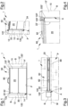
- the device 1 comprises a frame 10 provided with a pair of lateral contrast elements 12, 12' applied to the side edges B of an opening A of a known building, where said lateral contrast elements 12, 12' extend in a given direction D starting from a base 14, 14' set in substantial contact with a floor P.
- the floor P is illustrated in the attached figures as a box-shaped body having a flattened rectangular section, without thereby conditioning the scope of the present invention as defined by the appended claims.
- the two contrast elements 12 and 12' are obtained with two sectional bodies having an L section.
- the two contrast elements 12 and 12' are set facing one another, and each of them has a plane and longitudinal abutment 120, 120', set at the front in Figures 1-4 .
- the two abutments 120, 120' identify as a whole a reference plane M ( Figure 3 ), which is internally tangential to the abutments 120 and 120' and develops according to the given direction D.
- the device 1 further comprises a flood barrier 20, which is laterally delimited by two sides 22, 22', shaped being set up against the abutments 120, 120', and a bottom edge 24.
- Said bottom edge 24 is shaped for coupling with the floor P between the contrast elements 12, 12' and can have a cross section shaped in a substantially rectangular or semi-circular manner, or having a V-shape, according to the conformation of the floor P between the two contrast elements 12 and 12'.
- the edge 24 is rectangular, without this in any way limiting the scope of the present invention as defined by the appended claims.
- the device 1 comprises elastic sealing members 30, which are arranged longitudinally between each abutment 120, 120' and each edge 22, 22' for coupling at the front the flood barrier 20 and the contrast elements 12, 12' in a hydraulically sealed manner.
- the flood barrier 20 has a sealing element 40 constituted by a strip of elastomeric material, which, for practical reasons is designated by the same reference number 40 and has the purpose of exerting a sealing action at the level of the bottom edge 24.
- this strip 40 must necessarily be set at the interface between the flood barrier 20 and the floor P to exert its own hydraulic sealing action at the base of the flood barrier 20, so that falling within the scope of the present invention is also the version of the device 1 in which said strip 40 is applied to the floor P at the moment of installation of the device 1 itself.
- the device 1 further comprises engagement members 50, which are carried by the contrast elements 12, 12' for holding the flood barrier 20 at the front against the countering action of the elastic sealing means 30.
- the engagement members 50 comprise a pin 52 for each base 14, where said pin is carried parallel to and longitudinally facing the respective abutment 120/120' for delimiting, together with the latter, a space, the depth of which locally approximates the thickness of the corresponding side 22, 22' of the flood barrier 20.
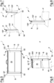
- Each side 22, 22' of the flood barrier 20 is delimited at the top by a hollow portion 220, 220', which houses a roller 222/222', rotatably carried in a direction transverse to the direction D.
- Each contrast element 12, 12' is delimited at the top by a head piece 122, 122', the width of which is greater than a thickness of the flood barrier 20.
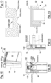
- Each head piece 122/122' ( Figure 13 ) has thrust members 1220, 1220' designed to press the flood barrier against the floor P.
- thrust members 1220/1220' are designed to act by shape fitting and, in particular, they comprise a substantially cylindrical central seat 1222, 1222' for the roller 222, 222' and a front portion 1224, 1224', which is provided for attachment of the head piece 122, 122' and has a thickness that increases in the direction of the seat 1220, 1220', and is hence shaped like an inclined plane.
- the device 1 comprises safety members 60 designed to block the sides 22, 22' of the flood barrier 20 against the abutments 120, 120' and, at the same time, the edge 24 against the floor P.
- the safety members 60 comprise a latch 62 for each side of the flood barrier 20, where each latch is carried at the top by the flood barrier 20 in a position facing the respective head piece 122, 122' with the bolt mobile between a neutral position where it does not project beyond the flood barrier 20 and an operative position where it partially projects with respect to the flood barrier 20 and interferes with the corresponding head piece 122, 122' in a respective housing 1226, 1226'.
- At least one handle 80 is applied to the flood barrier; in Figure 1 , the handle 80 is single, given the small dimensions of the flood barrier 20 that used as model for illustrating the structural characteristics of the present invention.
- the flood barrier 20 is arranged neatly with the sides 22 and 22' inclined with respect to the contrast elements 12 and 12', and the handle 80 can be used to turn the flood barrier 20 itself in the clockwise direction as viewed in Figure 10 , after it has been brought into contact with the front portion 1222/1222' of each head piece 122/122'.
- latches 62 enables definitive stabilization of this operating condition, which - it may be pointed out - has been brought about by exerting an action of pressure sufficient to overcome the elastic resistance of the elastic sealing members 30, which are in fact arranged longitudinally between each abutment 120, 120' and each edge 22, 22', with the effect of coupling at the front the flood barrier 20 and the sealing contrast elements 12, 12'.
- the anti-flood device 1 can be used not only to prevent entry of water through the openings (doors or windows) of a building, by providing sealed stretches in combination with the side edges B and the respective floor portions P, but also to prevent access of liquids into subways, tunnels, or underground passages, which are provided with parallel sides or sides rendered such at least for the vertical extension of the flood barriers used.
- Figure 17 illustrates an opening A particularly extensive in width.
- the flow of the liquid to be stopped could be particularly significant, both in terms of mass and in terms of power associated with the incoming mass of liquid.
- an anti-deflection unit 90 comprising a plurality of vertical latches 91 distributed at the bottom along the flood barrier 20 and provided with bolts 92 mobile in a vertical direction selectively between a neutral position and a position of engagement of a hole 94, made in the floor P in front of or behind the projection on the ground of the flood barrier 20.
- Each hole 94 houses a bushing 96 of a known type, vertically accessible by a bolt 92 but normally closed by a base (known and not illustrated) mobile vertically towards the bottom of the bushing 96 following upon displacement of the respective bolt 92 from a neutral position to a position of engagement against the thrust of a spring, known and not illustrated. It may well be understood that the purpose of the mobile base of each bushing 96 is to prevent intrusion of dirt or obstructing bodies into the bushing 96 itself.
- the anti-flood device 1 can be validly used for overcoming the drawbacks of the prior art illustrated above in a simple and inexpensive manner, thanks to the structural characteristics described above, which can be modified, without thereby departing from the scope of the present invention as defined by the appended claims.
Landscapes
- Engineering & Computer Science (AREA)
- Structural Engineering (AREA)
- Architecture (AREA)
- Civil Engineering (AREA)
- Specific Sealing Or Ventilating Devices For Doors And Windows (AREA)
- Arrangement Of Elements, Cooling, Sealing, Or The Like Of Lighting Devices (AREA)
- Developing Agents For Electrophotography (AREA)
- Electrical Discharge Machining, Electrochemical Machining, And Combined Machining (AREA)
- Paper (AREA)
- Revetment (AREA)
Claims (9)
- Eine Hochwasserschutzvorrichtung (1), die Folgendes beinhaltet: einen Rahmen (10), der mit einem Paar lateraler Kontrastelemente (12, 12') versehen ist, die in einer gegebenen Richtung (D), angefangen von einer Basis (14, 14'), die mit einem Boden (P) in Kontakt steht, langgestreckt sind und einander zugewandt sind, wobei jedes Kontrastelement (12, 12') einen längslaufenden Anschlag (120, 120') aufweist, wobei die zwei Anschläge (120, 120') eine Bezugsebene (M) identifizieren, die gemäß der gegebenen Richtung (D) verläuft; und eine Hochwasserbarriere (20), die seitlich von zwei Seiten (22, 22'), die so geformt sind, dass sie den Anschlägen (120, 120') zugewandt sind, und von einer unteren Kante (24), die zum Koppeln mit dem Boden (P) zwischen den Kontrastelementen (12, 12') geformt ist, begrenzt ist; elastische Dichtungsmittel (30), die längslaufend zwischen jedem Anschlag (120, 120') und jeder Kante (22, 22') zum Koppeln der Hochwasserbarriere (20) an der Vorderseite und der Kontrastelemente (12, 12') in einer hydraulisch dichten Weise angeordnet sind, Dichtungsmittel (40), die zwischen der Hochwasserbarriere (20) und dem Boden (P) zum Ausüben einer Dichtungswirkung auf die Bodenkante (24) angeordnet sind, Befestigungsmittel (50), die von den Kontrastelementen (12, 12') getragen werden, zum Halten der Hochwasserbarriere (20) an der Vorderseite gegen die Konterwirkung der elastischen Dichtungsmittel (30);
dadurch gekennzeichnet, dass jede Seite (22, 22') an der Oberseite von einem hohlen Abschnitt (220, 220') begrenzt ist, in dem eine Rolle (222, 222') untergebracht ist, die in einer drehbaren Weise in einer zur Richtung (D) querlaufenden Richtung getragen wird; jedes Kontrastelement (12, 12') an der Oberseite von einem Kopfstück (122, 122') begrenzt ist, das Druckmittel (1222, 1222') aufweist, die ausgelegt sind, um durch Formpassung auf jede jeweilige Rolle (222, 222') die Hochwasserbarriere (20) gegen den Boden (P) zu drücken. - Vorrichtung gemäß Anspruch 1, dadurch gekennzeichnet, dass mindestens ein Kopfstück (122, 122') eine Breite aufweist, die größer als die Hochwasserbarriere (20) ist; die Druckmittel (1222, 1222') einen im Wesentlichen zylindrischen mittigen Sitz (1220, 1220') für die Rolle (222, 222') und einen Vorderseitenabschnitt (1224, 1224') zur Befestigung des Kopfstücks (122, 122'), der eine Dicke aufweist, die in der Richtung des Sitzes (1220, 1220') zunimmt, beinhalten.
- Vorrichtung gemäß Anspruch 1 oder 2, dadurch gekennzeichnet, dass die Befestigungsmittel (50) einen Stift (52) für jede der Basen (14) beinhalten, der getragen wird, um dem Anschlag (120, 120') zugewandt zu sein, um einen Raum zu begrenzen, dessen Tiefe einer Dicke der entsprechenden Seite (22, 22') der Hochwasserbarriere (20) nahe kommt.
- Vorrichtung gemäß einem der vorhergehenden Ansprüche, dadurch gekennzeichnet, dass sie Sicherheitsmittel (60) beinhaltet, die ausgelegt sind, um die Seiten (22, 22') der Hochwasserbarriere (20) gegen die Anschläge (120, 120') und die Kante (24) gegen den Boden (P) zu blockieren.
- Vorrichtung gemäß Anspruch 4, dadurch gekennzeichnet, dass die Sicherheitsmittel (60) mindestens einen Riegel (62) beinhalten, der an der Oberseite der Hochwasserbarriere (20) auf der Seite (22, 22') in einer überschauenden Position des jeweiligen Kopfstücks (122, 122') beweglich zwischen einer vollständig überlappenden neutralen Position mit der Hochwasserbarriere (20) und einer teilweise überlappenden Betriebsposition mit der Hochwasserbarriere (20) und einer Interferenzposition mit dem entsprechenden Kopfstück (122, 122') in einem jeweiligen Gehäuse (1224, 1224') getragen wird.
- Vorrichtung gemäß einem der vorhergehenden Ansprüche, dadurch gekennzeichnet, dass die Kante (24) konvex und V-förmig ist, ein Profilstab (70) mit einem V-förmigen Profil zwischen den Basen (14, 14') der Kontrastelemente (12, 12') des Bodens (P) bereitgestellt ist und einen konkaven Abschnitt (72) aufweist, der zum Unterbringen der Kante (24) in einer hydraulisch dichten Weise im Voraus angeordnet wird.
- Vorrichtung gemäß Anspruch 6, dadurch gekennzeichnet, dass sie einen Streifen (40) aus elastomerem Material zwischen dem Stab (70) und der Kante (24) beinhaltet.
- Vorrichtung gemäß einem der vorhergehenden Ansprüche, dadurch gekennzeichnet, dass sie Durchbiegungsschutzmittel (90) beinhaltet, die mit der Hochwasserbarriere (20) assoziiert und mit einer Vielzahl von Riegeln (91) versehen sind, die entlang der Hochwasserbarriere (20) verteilt und mit Bolzen (92), die ausgelegt sind, um ein im Boden (P) geschaffenes Loch (94) selektiv in Eingriff zu nehmen, versehen sind.
- Vorrichtung gemäß Anspruch 8, dadurch gekennzeichnet, dass in mindestens einem Loch (94) eine normalerweise geschlossene Buchse (96) untergebracht ist, die vertikal gegen den Druck einer Feder zugänglich ist.
Priority Applications (1)
| Application Number | Priority Date | Filing Date | Title |
|---|---|---|---|
| SM20230298T SMT202300298T1 (it) | 2019-07-18 | 2020-07-15 | Dispositivo antiallagamento |
Applications Claiming Priority (1)
| Application Number | Priority Date | Filing Date | Title |
|---|---|---|---|
| IT202019000002415U IT201900002415U1 (it) | 2019-07-18 | 2019-07-18 | Dispositivo antiallagamento |
Publications (4)
| Publication Number | Publication Date |
|---|---|
| EP3767064A2 EP3767064A2 (de) | 2021-01-20 |
| EP3767064A3 EP3767064A3 (de) | 2021-04-28 |
| EP3767064B1 true EP3767064B1 (de) | 2023-06-07 |
| EP3767064C0 EP3767064C0 (de) | 2023-06-07 |
Family
ID=71894589
Family Applications (1)
| Application Number | Title | Priority Date | Filing Date |
|---|---|---|---|
| EP20185944.4A Active EP3767064B1 (de) | 2019-07-18 | 2020-07-15 | Hochwasserbarriere |
Country Status (5)
| Country | Link |
|---|---|
| EP (1) | EP3767064B1 (de) |
| ES (1) | ES2955603T3 (de) |
| IT (1) | IT201900002415U1 (de) |
| PL (1) | PL3767064T3 (de) |
| SM (1) | SMT202300298T1 (de) |
Families Citing this family (1)
| Publication number | Priority date | Publication date | Assignee | Title |
|---|---|---|---|---|
| IT202300022578A1 (it) * | 2023-10-27 | 2025-04-27 | Acquastop S R L | Paratia anti allagamento ad assetto regolabile |
Family Cites Families (6)
| Publication number | Priority date | Publication date | Assignee | Title |
|---|---|---|---|---|
| GB9007508D0 (en) * | 1990-04-03 | 1990-05-30 | Tracey Clifford B | Emergency flood barrier |
| GB2327697A (en) * | 1997-07-25 | 1999-02-03 | Meurig Raymond Jones | Flood barrier |
| US7523589B1 (en) * | 2006-03-31 | 2009-04-28 | The Presray Corporation | Portable flood barrier panel |
| EP2703563A3 (de) * | 2012-08-01 | 2015-03-18 | EM Solutions Srl | Stütz-, Befestigungs- und Lösesystem für zeitweilige Barrieren |
| CN107120051B (zh) * | 2017-07-06 | 2019-07-05 | 高瞻 | 一种手插式挡水门 |
| GB2567688B (en) * | 2017-10-20 | 2021-07-07 | Frederick Turner | Flood barrier gate |
-
2019
- 2019-07-18 IT IT202019000002415U patent/IT201900002415U1/it unknown
-
2020
- 2020-07-15 SM SM20230298T patent/SMT202300298T1/it unknown
- 2020-07-15 ES ES20185944T patent/ES2955603T3/es active Active
- 2020-07-15 PL PL20185944.4T patent/PL3767064T3/pl unknown
- 2020-07-15 EP EP20185944.4A patent/EP3767064B1/de active Active
Also Published As
| Publication number | Publication date |
|---|---|
| IT201900002415U1 (it) | 2021-01-18 |
| EP3767064A2 (de) | 2021-01-20 |
| PL3767064T3 (pl) | 2023-10-23 |
| EP3767064A3 (de) | 2021-04-28 |
| ES2955603T3 (es) | 2023-12-04 |
| EP3767064C0 (de) | 2023-06-07 |
| SMT202300298T1 (it) | 2023-11-13 |
Similar Documents
| Publication | Publication Date | Title |
|---|---|---|
| US6883273B2 (en) | Hydraulically operated overhead door | |
| EP3767064B1 (de) | Hochwasserbarriere | |
| EP1645714B1 (de) | Verbund zwischen Rahmen und Füllung | |
| KR20150066731A (ko) | 탈부착식 방수판이 구비된 셔터 | |
| CN111139839A (zh) | 一种基坑围护系统及其施工方法 | |
| JP2020026702A (ja) | 堤防の透視窓構造 | |
| CA1064771A (en) | Reversible window | |
| DE202008012907U1 (de) | Anordnung zum zeitweiligen Schutz von Bauwerken gegen Hochwasser | |
| DE9014950U1 (de) | Vorrichtung zur Sicherung von Objekten gegen ein Eindringen von Wasser | |
| KR102932352B1 (ko) | 시트파일 차수벽 시공을 위한 천공작업용 가이드부재 | |
| AT521543B1 (de) | Schutzvorrichtung für Roll- und Sektionaltore | |
| EP1728928A2 (de) | Mobile Hochwasserschutzeinrichtung | |
| DE102010052470A1 (de) | Markise mit Abstützung und magnetischer Fixierung | |
| KR101539718B1 (ko) | 소음 차단이 향상된 가설방음벽 | |
| KR200434748Y1 (ko) | 가동 보의 유압식 전도수문 | |
| KR102611157B1 (ko) | 양문개폐형 차수장치 | |
| DE102005048304A1 (de) | Hochwasserschutzeinrichtung | |
| AT519889B1 (de) | Rollgitter-Toranlage | |
| KR101574680B1 (ko) | 수문 개폐용 사프트 처짐 방지장치 | |
| CN223593289U (zh) | 一种具有侧装式密封条的防洪闸 | |
| EP0678629B1 (de) | Verbauvorrichtung | |
| LU504305B1 (de) | Eine Dichtungskonstruktion für eine unterirdische Schlitzwand | |
| CN217950153U (zh) | 一种组装式窗结构 | |
| DE202006018777U1 (de) | Hochwasserschutzvorrichtung | |
| CN218233628U (zh) | 一种挖掘机的防撞结构 |
Legal Events
| Date | Code | Title | Description |
|---|---|---|---|
| PUAI | Public reference made under article 153(3) epc to a published international application that has entered the european phase |
Free format text: ORIGINAL CODE: 0009012 |
|
| STAA | Information on the status of an ep patent application or granted ep patent |
Free format text: STATUS: THE APPLICATION HAS BEEN PUBLISHED |
|
| AK | Designated contracting states |
Kind code of ref document: A2 Designated state(s): AL AT BE BG CH CY CZ DE DK EE ES FI FR GB GR HR HU IE IS IT LI LT LU LV MC MK MT NL NO PL PT RO RS SE SI SK SM TR |
|
| AX | Request for extension of the european patent |
Extension state: BA ME |
|
| PUAL | Search report despatched |
Free format text: ORIGINAL CODE: 0009013 |
|
| AK | Designated contracting states |
Kind code of ref document: A3 Designated state(s): AL AT BE BG CH CY CZ DE DK EE ES FI FR GB GR HR HU IE IS IT LI LT LU LV MC MK MT NL NO PL PT RO RS SE SI SK SM TR |
|
| AX | Request for extension of the european patent |
Extension state: BA ME |
|
| RIC1 | Information provided on ipc code assigned before grant |
Ipc: E06B 9/00 20060101AFI20210319BHEP |
|
| STAA | Information on the status of an ep patent application or granted ep patent |
Free format text: STATUS: REQUEST FOR EXAMINATION WAS MADE |
|
| 17P | Request for examination filed |
Effective date: 20211028 |
|
| RBV | Designated contracting states (corrected) |
Designated state(s): AL AT BE BG CH CY CZ DE DK EE ES FI FR GB GR HR HU IE IS IT LI LT LU LV MC MK MT NL NO PL PT RO RS SE SI SK SM TR |
|
| GRAP | Despatch of communication of intention to grant a patent |
Free format text: ORIGINAL CODE: EPIDOSNIGR1 |
|
| STAA | Information on the status of an ep patent application or granted ep patent |
Free format text: STATUS: GRANT OF PATENT IS INTENDED |
|
| INTG | Intention to grant announced |
Effective date: 20221118 |
|
| GRAS | Grant fee paid |
Free format text: ORIGINAL CODE: EPIDOSNIGR3 |
|
| GRAA | (expected) grant |
Free format text: ORIGINAL CODE: 0009210 |
|
| STAA | Information on the status of an ep patent application or granted ep patent |
Free format text: STATUS: THE PATENT HAS BEEN GRANTED |
|
| AK | Designated contracting states |
Kind code of ref document: B1 Designated state(s): AL AT BE BG CH CY CZ DE DK EE ES FI FR GB GR HR HU IE IS IT LI LT LU LV MC MK MT NL NO PL PT RO RS SE SI SK SM TR |
|
| REG | Reference to a national code |
Ref country code: GB Ref legal event code: FG4D |
|
| REG | Reference to a national code |
Ref country code: CH Ref legal event code: EP Ref country code: AT Ref legal event code: REF Ref document number: 1575604 Country of ref document: AT Kind code of ref document: T Effective date: 20230615 |
|
| REG | Reference to a national code |
Ref country code: DE Ref legal event code: R096 Ref document number: 602020011611 Country of ref document: DE |
|
| U01 | Request for unitary effect filed |
Effective date: 20230707 |
|
| U07 | Unitary effect registered |
Designated state(s): AT BE BG DE DK EE FI FR IT LT LU LV MT NL PT SE SI Effective date: 20230719 |
|
| REG | Reference to a national code |
Ref country code: LT Ref legal event code: MG9D |
|
| PG25 | Lapsed in a contracting state [announced via postgrant information from national office to epo] |
Ref country code: NO Free format text: LAPSE BECAUSE OF FAILURE TO SUBMIT A TRANSLATION OF THE DESCRIPTION OR TO PAY THE FEE WITHIN THE PRESCRIBED TIME-LIMIT Effective date: 20230907 |
|
| U20 | Renewal fee for the european patent with unitary effect paid |
Year of fee payment: 4 Effective date: 20230929 |
|
| PG25 | Lapsed in a contracting state [announced via postgrant information from national office to epo] |
Ref country code: RS Free format text: LAPSE BECAUSE OF FAILURE TO SUBMIT A TRANSLATION OF THE DESCRIPTION OR TO PAY THE FEE WITHIN THE PRESCRIBED TIME-LIMIT Effective date: 20230607 Ref country code: HR Free format text: LAPSE BECAUSE OF FAILURE TO SUBMIT A TRANSLATION OF THE DESCRIPTION OR TO PAY THE FEE WITHIN THE PRESCRIBED TIME-LIMIT Effective date: 20230607 Ref country code: GR Free format text: LAPSE BECAUSE OF FAILURE TO SUBMIT A TRANSLATION OF THE DESCRIPTION OR TO PAY THE FEE WITHIN THE PRESCRIBED TIME-LIMIT Effective date: 20230908 |
|
| REG | Reference to a national code |
Ref country code: ES Ref legal event code: FG2A Ref document number: 2955603 Country of ref document: ES Kind code of ref document: T3 Effective date: 20231204 |
|
| PG25 | Lapsed in a contracting state [announced via postgrant information from national office to epo] |
Ref country code: SK Free format text: LAPSE BECAUSE OF FAILURE TO SUBMIT A TRANSLATION OF THE DESCRIPTION OR TO PAY THE FEE WITHIN THE PRESCRIBED TIME-LIMIT Effective date: 20230607 |
|
| PG25 | Lapsed in a contracting state [announced via postgrant information from national office to epo] |
Ref country code: IS Free format text: LAPSE BECAUSE OF FAILURE TO SUBMIT A TRANSLATION OF THE DESCRIPTION OR TO PAY THE FEE WITHIN THE PRESCRIBED TIME-LIMIT Effective date: 20231007 |
|
| PG25 | Lapsed in a contracting state [announced via postgrant information from national office to epo] |
Ref country code: SK Free format text: LAPSE BECAUSE OF FAILURE TO SUBMIT A TRANSLATION OF THE DESCRIPTION OR TO PAY THE FEE WITHIN THE PRESCRIBED TIME-LIMIT Effective date: 20230607 Ref country code: RO Free format text: LAPSE BECAUSE OF FAILURE TO SUBMIT A TRANSLATION OF THE DESCRIPTION OR TO PAY THE FEE WITHIN THE PRESCRIBED TIME-LIMIT Effective date: 20230607 Ref country code: IS Free format text: LAPSE BECAUSE OF FAILURE TO SUBMIT A TRANSLATION OF THE DESCRIPTION OR TO PAY THE FEE WITHIN THE PRESCRIBED TIME-LIMIT Effective date: 20231007 Ref country code: CZ Free format text: LAPSE BECAUSE OF FAILURE TO SUBMIT A TRANSLATION OF THE DESCRIPTION OR TO PAY THE FEE WITHIN THE PRESCRIBED TIME-LIMIT Effective date: 20230607 |
|
| PGFP | Annual fee paid to national office [announced via postgrant information from national office to epo] |
Ref country code: SM Payment date: 20231009 Year of fee payment: 4 |
|
| REG | Reference to a national code |
Ref country code: CH Ref legal event code: PL |
|
| REG | Reference to a national code |
Ref country code: DE Ref legal event code: R097 Ref document number: 602020011611 Country of ref document: DE |
|
| PG25 | Lapsed in a contracting state [announced via postgrant information from national office to epo] |
Ref country code: MC Free format text: LAPSE BECAUSE OF FAILURE TO SUBMIT A TRANSLATION OF THE DESCRIPTION OR TO PAY THE FEE WITHIN THE PRESCRIBED TIME-LIMIT Effective date: 20230607 |
|
| PG25 | Lapsed in a contracting state [announced via postgrant information from national office to epo] |
Ref country code: MC Free format text: LAPSE BECAUSE OF FAILURE TO SUBMIT A TRANSLATION OF THE DESCRIPTION OR TO PAY THE FEE WITHIN THE PRESCRIBED TIME-LIMIT Effective date: 20230607 |
|
| PLBE | No opposition filed within time limit |
Free format text: ORIGINAL CODE: 0009261 |
|
| STAA | Information on the status of an ep patent application or granted ep patent |
Free format text: STATUS: NO OPPOSITION FILED WITHIN TIME LIMIT |
|
| REG | Reference to a national code |
Ref country code: IE Ref legal event code: MM4A |
|
| PG25 | Lapsed in a contracting state [announced via postgrant information from national office to epo] |
Ref country code: CH Free format text: LAPSE BECAUSE OF NON-PAYMENT OF DUE FEES Effective date: 20230731 |
|
| 26N | No opposition filed |
Effective date: 20240308 |
|
| PG25 | Lapsed in a contracting state [announced via postgrant information from national office to epo] |
Ref country code: IE Free format text: LAPSE BECAUSE OF NON-PAYMENT OF DUE FEES Effective date: 20230715 |
|
| PG25 | Lapsed in a contracting state [announced via postgrant information from national office to epo] |
Ref country code: IE Free format text: LAPSE BECAUSE OF NON-PAYMENT OF DUE FEES Effective date: 20230715 |
|
| U20 | Renewal fee for the european patent with unitary effect paid |
Year of fee payment: 5 Effective date: 20240731 |
|
| GBPC | Gb: european patent ceased through non-payment of renewal fee |
Effective date: 20240715 |
|
| PG25 | Lapsed in a contracting state [announced via postgrant information from national office to epo] |
Ref country code: SM Free format text: LAPSE BECAUSE OF NON-PAYMENT OF DUE FEES Effective date: 20250211 |
|
| PG25 | Lapsed in a contracting state [announced via postgrant information from national office to epo] |
Ref country code: GB Free format text: LAPSE BECAUSE OF NON-PAYMENT OF DUE FEES Effective date: 20240715 |
|
| PG25 | Lapsed in a contracting state [announced via postgrant information from national office to epo] |
Ref country code: CY Free format text: LAPSE BECAUSE OF FAILURE TO SUBMIT A TRANSLATION OF THE DESCRIPTION OR TO PAY THE FEE WITHIN THE PRESCRIBED TIME-LIMIT; INVALID AB INITIO Effective date: 20200715 |
|
| PG25 | Lapsed in a contracting state [announced via postgrant information from national office to epo] |
Ref country code: HU Free format text: LAPSE BECAUSE OF FAILURE TO SUBMIT A TRANSLATION OF THE DESCRIPTION OR TO PAY THE FEE WITHIN THE PRESCRIBED TIME-LIMIT; INVALID AB INITIO Effective date: 20200715 |
|
| U20 | Renewal fee for the european patent with unitary effect paid |
Year of fee payment: 6 Effective date: 20250725 |
|
| PGFP | Annual fee paid to national office [announced via postgrant information from national office to epo] |
Ref country code: ES Payment date: 20250801 Year of fee payment: 6 |
|
| PGFP | Annual fee paid to national office [announced via postgrant information from national office to epo] |
Ref country code: PL Payment date: 20250701 Year of fee payment: 6 |
|
| PG25 | Lapsed in a contracting state [announced via postgrant information from national office to epo] |
Ref country code: TR Free format text: LAPSE BECAUSE OF FAILURE TO SUBMIT A TRANSLATION OF THE DESCRIPTION OR TO PAY THE FEE WITHIN THE PRESCRIBED TIME-LIMIT Effective date: 20230607 |