EP3767128A1 - Ancrage de point de levage de boucle de câble - Google Patents
Ancrage de point de levage de boucle de câble Download PDFInfo
- Publication number
- EP3767128A1 EP3767128A1 EP19186877.7A EP19186877A EP3767128A1 EP 3767128 A1 EP3767128 A1 EP 3767128A1 EP 19186877 A EP19186877 A EP 19186877A EP 3767128 A1 EP3767128 A1 EP 3767128A1
- Authority
- EP
- European Patent Office
- Prior art keywords
- base
- wire rope
- hoist point
- ferrule
- anchor
- Prior art date
- Legal status (The legal status is an assumption and is not a legal conclusion. Google has not performed a legal analysis and makes no representation as to the accuracy of the status listed.)
- Withdrawn
Links
Images

Classifications
-
- F—MECHANICAL ENGINEERING; LIGHTING; HEATING; WEAPONS; BLASTING
- F16—ENGINEERING ELEMENTS AND UNITS; GENERAL MEASURES FOR PRODUCING AND MAINTAINING EFFECTIVE FUNCTIONING OF MACHINES OR INSTALLATIONS; THERMAL INSULATION IN GENERAL
- F16G—BELTS, CABLES, OR ROPES, PREDOMINANTLY USED FOR DRIVING PURPOSES; CHAINS; FITTINGS PREDOMINANTLY USED THEREFOR
- F16G11/00—Means for fastening cables or ropes to one another or to other objects; Caps or sleeves for fixing on cables or ropes
- F16G11/02—Means for fastening cables or ropes to one another or to other objects; Caps or sleeves for fixing on cables or ropes with parts deformable to grip the cable or cables; Fastening means which engage a sleeve or the like fixed on the cable
-
- F—MECHANICAL ENGINEERING; LIGHTING; HEATING; WEAPONS; BLASTING
- F16—ENGINEERING ELEMENTS AND UNITS; GENERAL MEASURES FOR PRODUCING AND MAINTAINING EFFECTIVE FUNCTIONING OF MACHINES OR INSTALLATIONS; THERMAL INSULATION IN GENERAL
- F16G—BELTS, CABLES, OR ROPES, PREDOMINANTLY USED FOR DRIVING PURPOSES; CHAINS; FITTINGS PREDOMINANTLY USED THEREFOR
- F16G11/00—Means for fastening cables or ropes to one another or to other objects; Caps or sleeves for fixing on cables or ropes
- F16G11/14—Devices or coupling-pieces designed for easy formation of adjustable loops, e.g. choker hooks; Hooks or eyes with integral parts designed to facilitate quick attachment to cables or ropes at any point, e.g. by forming loops
-
- A—HUMAN NECESSITIES
- A62—LIFE-SAVING; FIRE-FIGHTING
- A62B—DEVICES, APPARATUS OR METHODS FOR LIFE-SAVING
- A62B35/00—Safety belts or body harnesses; Similar equipment for limiting displacement of the human body, especially in case of sudden changes of motion
- A62B35/0043—Lifelines, lanyards, and anchors therefore
- A62B35/0068—Anchors
Definitions
- the invention relates to a hoist point anchor according to the preamble of claim 1.
- a hoist point anchor comprises a base, wherein the base has a contact surface for contacting a ceiling and wherein the base has a plurality of anchor holes for receiving anchor bolts for anchoring the base to the ceiling, and a wire rope forming a wire rope loop for attaching a hook, wherein the wire rope loop is attached to the base.
- hoist point anchors When work is to be carried out in elevator shafts, hoist point anchors might be required. These anchors are mounted to the ceiling of the elevator shaft and provide an eye, on which hoisting equipment might be suspended.
- a hoist point anchor that comprises a piece of wire rope, both ends of which are fixed within a single sleeve, so that the wire rope forms an eye.
- the sleeve projects radially from a baseplate, which is intended to be anchored to the ceiling of a shaft.
- HAP 1.15 Another hoist point anchor, named "HAP 1.15", is disclosed at https://www.hilti.com/c/CLS_FASTENER_7135/CLS_CASTIN_ANCHOR_CHANNELS_7135/ CLS_ACCESSORIES_FOR_ELEVATORS_7135/2032179.
- This anchor comprises a baseplate to be anchored to the ceiling, a trunnion projecting from the baseplate, and a shackle attached to the trunnion.
- the base passes through the wire rope loop.
- the wire rope loop winds around a dedicated section of the base, i.e. the base pierces through the wire rope loop.
- the overall height of the anchor more particular the overall height of the rigid parts of the anchor, can be particularly low, since the interlaced arrangement of the wire rope and the base allows to locate the mechanical connection between the wire rope and the base within the base, without a need for protruding fittings.
- Said low overall height of the anchor can provide particularly high versatility, and especially, it can provide particularly high headroom in elevator shafts.
- the interlaced design can provide a particularly efficient force transfer between base and wire rope, thereby providing particularly good load performance.
- the contact surface is for contacting a ceiling, i.e. a horizontal surface that forms the top part inside a room, in particular inside an elevator shaft.
- the contact surface is for contacting a flat ceiling.
- the contact surface is preferably also flat.
- the contact surface can have one or more of recesses, e.g. for housing the wire loop and its fittings or for saving material.
- the base can have a ribbing, with the contact surface provided on the ribbing. Each anchor hole allows passing an anchor through the base into the ceiling, for anchoring the base to the ceiling.
- the wire rope can comprise a plurality of strands of metal wire twisted into a helix, thereby forming a composite rope structure.
- the wire rope can preferably be a steel wire rope.
- the wire rope loop forms an eye, into which a hook can be hooked.
- the wire rope loop is attached, i.e. connected, to the base, in particular at both opposite end regions of the wire rope loop, so that the wire rope loop can transfer tensile forces from a hook hooked into the wire rope loop into the base.
- the first end region of the wire rope is arranged parallel to the contact surface and/or the second end region of the wire rope is arranged parallel to the contact surface. This can further reduce the overall height of the anchor.
- the hoist point anchor comprises a first ferrule and a second ferrule, wherein the first ferrule surrounds and is fixed to the wire rope in its first end region, wherein the second ferrule surrounds and is fixed to the wire rope in its second end region, and wherein the base engages the first ferrule and the second ferrule.
- two separate ferrules are used for fixing the respective end regions of the wire rope. This provides a comparatively high degree of geometric design freedom, which can, amongst others, be advantageous in view of anchor size.
- stop holes provided within the base, which are made of a size to pass the wire rope, but not wide enough to permit the respective ferrule to be drawn through it.
- the stop holes are provided in fork structures provided on the base. In this case, the stop holes are laterally open for inserting the wire rope.
- the first ferrule and the second ferrule have parallel longitudinal axes. This can be advantageous in view of anchor size.
- the axes of the ferrules extend through the opening of the respective ferrule, in the longitudinal direction of the respective ferrule.
- the base comprises a node portion and a plurality of mounting arms projecting from the node portion, wherein at least one anchor hole is provided in each of the mounting arms.
- the base comprises four mounting arms, arranged to form a cross.
- the base can have supplementary arms without a mounting hole, for example for stabilizing purposes.
- the node portion of the base which passes through the wire rope loop. This can allow particular efficient force transfer between the wire rope loop and the base, further reducing the amount of required material without significantly compromising on mechanical properties.
- the contact surface may preferably be located on the mounting arms, in particularly on the mounting arms only.
- the contact surface could be a discontinuous surface, consisting of a plurality of separate sub-surfaces, wherein one of the sub-surfaces is located on each mounting arm. Having the contact surface at the mounting arms can be advantageous, amongst others, in view of device stability, robustness and size.
- the base can comprise, preferably two, thimble grooves that guide the wire rope loop.
- the wire rope is disposed in the thimble grooves so that the walls of the thimble grooves delimit deflection of the wire rope loop. Thimble grooves can thus form an integrated thimble in the base.
- the base can preferably be monolithic, i.e. consist of one piece. This can be advantageous in view of robustness.
- the base can consist of metal, preferably cast metal, which can also be coated with other materials or have inlays consisting of other materials.
- the invention also relates to a building structure comprising a ceiling and the described hoist point anchor fixed to the ceiling by anchor bolts passing through the anchor holes, so that the contact surface of the base of the hoist point anchor faces the ceiling.
- the hoist point anchor is mounted as intended.
- the contact surface of the base touches the ceiling.
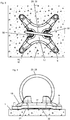
- the figures show an example of an inventive hoist point anchor.
- the hoist point anchor comprises a cruciform base 10 comprising a node portion 17 and four mounting arms 18, each of which projects from the node portion 17.
- the base 10 has a flat contact surface 11 intended to be placed adjacent to a flat ceiling 1.
- the contact surface 11 consists of four separate sub-surfaces, wherein one of these sub-surfaces is arranged on each mounting arm 18.
- the anchor holes 19 are intended to receive anchor bolts 9 for anchoring the base 10 to the ceiling 1.
- Each anchor hole 19 is surrounded by a sub-surface of the contact surface 11.
- the contact surface 11 is located remote from the node portion 17.
- the base 10 preferably consists of cast metal, which might additionally be coated.
- the base 10 is monolithic.
- the hoist point anchor moreover comprises a wire rope 20 having a first end region 21 and a second end region 22.
- the wire rope 20 is disposed in the form of a wire rope loop 28, which is wrapped around the base 10, in particular around its node portion 17, i.e. the base 10, in particular its node portion 17, passes through the wire rope loop 28.
- the wire rope loop 28 has a slack portion, which projects from the base 10 at the underside of the base 10, i.e. at the side of the base 10 opposite the contact surface 11, and this slack portion forms an eye for attaching a hook.
- the legs of the wire rope loop 28 i.e. the end regions 21 and 22 of the wire rope 20
- the first end region 21 of the wire rope 20 is disposed in a first ferrule 31 and connected thereto, and the second end region 22 of the wire rope 20 is disposed in a second ferrule 32 and connected thereto, wherein the connection to the ferrules 31, 32 can for example be a swaged connection.
- the base 10 comprises a first ferrule receptacle 13, in which the first ferrule 31 and the first end region 21 of the wire rope 20 are disposed, as well as a second ferrule receptacle 14, in which the second ferrule 32 and the second end region 22 of the wire rope 20 are disposed. Both ferrule receptacles 13, 14 are open towards the flat ceiling 1 to which the base 10 is attached.
- the first ferrule receptacle 13 is laterally delimited by a first fork 15, through which the wire rope 20 passes.
- the first fork 15 is wider than the wire rope 20 but narrower than the first ferrule 31.
- the first fork 15 thus forms a counter bearing which secures the first ferrule 31 and therefore the first end region 21 of the wire rope 20 to the base 10.
- the second ferrule receptacle 14 is laterally delimited by a second fork 16, through which the wire rope 20 passes.
- the second fork 16 is wider than the wire rope 20 but narrower than the second ferrule 32.
- the second fork 16 thus forms a counter bearing which secures the second ferrule 32 and therefore the second end region 22 of the wire rope 20 to the base 10.
- a separate bolted fixing plate 40 secures the wire rope 20 in the forks 15, 16.
- the base 10 has two thimble grooves 50, in which the wire rope 20 is disposed.
- the thimble grooves 50 guide and laterally support the wire rope 20.
- the thimble grooves 50 form a constriction in the base 10, in particular in the node portion 17 thereof.
- the thimble grooves 50 constitutes an integrated thimble for stabilizing the wire rope loop 28.
Landscapes
- Engineering & Computer Science (AREA)
- General Engineering & Computer Science (AREA)
- Mechanical Engineering (AREA)
- Joining Of Building Structures In Genera (AREA)
- Lift-Guide Devices, And Elevator Ropes And Cables (AREA)
Priority Applications (4)
| Application Number | Priority Date | Filing Date | Title |
|---|---|---|---|
| EP19186877.7A EP3767128A1 (fr) | 2019-07-18 | 2019-07-18 | Ancrage de point de levage de boucle de câble |
| PCT/EP2020/069410 WO2021009005A1 (fr) | 2019-07-18 | 2020-07-09 | Ancrage de point de levage de boucle de fil métallique |
| EP20740567.1A EP3999759B1 (fr) | 2019-07-18 | 2020-07-09 | Ancrage de point de levage de boucle de câble |
| US17/628,033 US12498016B2 (en) | 2019-07-18 | 2020-07-09 | Wire loop hoist point anchor |
Applications Claiming Priority (1)
| Application Number | Priority Date | Filing Date | Title |
|---|---|---|---|
| EP19186877.7A EP3767128A1 (fr) | 2019-07-18 | 2019-07-18 | Ancrage de point de levage de boucle de câble |
Publications (1)
| Publication Number | Publication Date |
|---|---|
| EP3767128A1 true EP3767128A1 (fr) | 2021-01-20 |
Family
ID=67437905
Family Applications (2)
| Application Number | Title | Priority Date | Filing Date |
|---|---|---|---|
| EP19186877.7A Withdrawn EP3767128A1 (fr) | 2019-07-18 | 2019-07-18 | Ancrage de point de levage de boucle de câble |
| EP20740567.1A Active EP3999759B1 (fr) | 2019-07-18 | 2020-07-09 | Ancrage de point de levage de boucle de câble |
Family Applications After (1)
| Application Number | Title | Priority Date | Filing Date |
|---|---|---|---|
| EP20740567.1A Active EP3999759B1 (fr) | 2019-07-18 | 2020-07-09 | Ancrage de point de levage de boucle de câble |
Country Status (3)
| Country | Link |
|---|---|
| US (1) | US12498016B2 (fr) |
| EP (2) | EP3767128A1 (fr) |
| WO (1) | WO2021009005A1 (fr) |
Families Citing this family (3)
| Publication number | Priority date | Publication date | Assignee | Title |
|---|---|---|---|---|
| US20240376730A1 (en) * | 2023-05-08 | 2024-11-14 | Iron Fusion Enterprise, LLC | Swivel anchor |
| US11879256B1 (en) | 2023-07-20 | 2024-01-23 | Kevin King | Roof safety anchor |
| KR102667805B1 (ko) * | 2023-11-13 | 2024-05-22 | 이상은 | 건물 청소용 로프 고정장치 |
Citations (1)
| Publication number | Priority date | Publication date | Assignee | Title |
|---|---|---|---|---|
| EP2324701A1 (fr) * | 2009-11-23 | 2011-05-25 | Claudio Bortolussi | Système d'attachement |
Family Cites Families (12)
| Publication number | Priority date | Publication date | Assignee | Title |
|---|---|---|---|---|
| US434603A (en) * | 1890-08-19 | Broom-hanger | ||
| US4323273A (en) * | 1980-08-18 | 1982-04-06 | Sword Alexander F | Line ender |
| US5052869A (en) * | 1990-08-29 | 1991-10-01 | A. L. Hansen Mfg. Co. | Tie down assembly |
| US5630634A (en) * | 1994-12-27 | 1997-05-20 | Michael W. Stowe | Device for magnetically engaging objects having variable surface contours |
| US5774948A (en) * | 1997-04-04 | 1998-07-07 | Creative Wire & Tube Forming, Inc. | Tie-down ring |
| US8251410B1 (en) * | 2009-04-20 | 2012-08-28 | Armorworks Enterprises LLC | Armor hold-down assembly |
| US7651305B1 (en) * | 2009-06-10 | 2010-01-26 | The United States Of America As Represented By The Secretary Of The Navy | Retractable fitting |
| US8424638B1 (en) * | 2010-04-01 | 2013-04-23 | Karl Guthrie | Swivel anchor point for fall protection |
| US10036416B2 (en) * | 2013-10-03 | 2018-07-31 | Ty-Flot, Inc. | Swivel connector assembly |
| US12280624B2 (en) * | 2021-10-12 | 2025-04-22 | Miller Industries Towing Equipment Inc. | Self-aligning, rotating D-ring for recovery vehicles |
| USD1064612S1 (en) * | 2023-07-11 | 2025-03-04 | Guangzhou Tusunny Home Products Co., Ltd | Clothing clip |
| US11879256B1 (en) * | 2023-07-20 | 2024-01-23 | Kevin King | Roof safety anchor |
-
2019
- 2019-07-18 EP EP19186877.7A patent/EP3767128A1/fr not_active Withdrawn
-
2020
- 2020-07-09 WO PCT/EP2020/069410 patent/WO2021009005A1/fr not_active Ceased
- 2020-07-09 US US17/628,033 patent/US12498016B2/en active Active
- 2020-07-09 EP EP20740567.1A patent/EP3999759B1/fr active Active
Patent Citations (1)
| Publication number | Priority date | Publication date | Assignee | Title |
|---|---|---|---|---|
| EP2324701A1 (fr) * | 2009-11-23 | 2011-05-25 | Claudio Bortolussi | Système d'attachement |
Also Published As
| Publication number | Publication date |
|---|---|
| US12498016B2 (en) | 2025-12-16 |
| US20220275851A1 (en) | 2022-09-01 |
| EP3999759B1 (fr) | 2025-04-30 |
| EP3999759A1 (fr) | 2022-05-25 |
| WO2021009005A1 (fr) | 2021-01-21 |
Similar Documents
| Publication | Publication Date | Title |
|---|---|---|
| EP3999759B1 (fr) | Ancrage de point de levage de boucle de câble | |
| KR20010040287A (ko) | 견인 로프풀리 엘리베이터 | |
| JP2009190820A (ja) | 揚重冶具および鉄筋の揚重方法 | |
| CN101311098B (zh) | 电梯设备 | |
| HK40065319B (en) | Wire loop hoist point anchor | |
| HK40065319A (en) | Wire loop hoist point anchor | |
| CN211496571U (zh) | 自平衡吊具 | |
| JP2002255472A (ja) | 揚重用吊り天秤装置 | |
| US7150342B2 (en) | Elevator structure mounting system having horizontal member for reducing building loads at top of hoistway | |
| JP2020193057A (ja) | 回り止め具 | |
| CN211366682U (zh) | 一种组合式吊梁 | |
| CN109996752B (zh) | 用于提升机的坠落防护设备 | |
| CN212639665U (zh) | 一种吊具结构及架梁吊机 | |
| CN212655336U (zh) | 一种吊杆组件、吊具结构及架梁吊机 | |
| CN210214540U (zh) | 一种预制构件吊具 | |
| KR100514339B1 (ko) | 엘리베이터 장치 | |
| RU2361988C2 (ru) | Копер | |
| CN110550538B (zh) | 一种吊具 | |
| JP3225269U (ja) | 吊りピース | |
| JP3199539B2 (ja) | 重量長尺物の吊り起こし方法 | |
| CN110562832B (zh) | 一种用于曳引式建筑施工升降机的补偿链装置 | |
| CN218860130U (zh) | 一种吊具 | |
| JP3004731U (ja) | 多点吊り治具 | |
| CN210735959U (zh) | 一种多点弹性起吊装置 | |
| CN223422187U (zh) | 一种飞机组合吊具 |
Legal Events
| Date | Code | Title | Description |
|---|---|---|---|
| PUAI | Public reference made under article 153(3) epc to a published international application that has entered the european phase |
Free format text: ORIGINAL CODE: 0009012 |
|
| STAA | Information on the status of an ep patent application or granted ep patent |
Free format text: STATUS: THE APPLICATION HAS BEEN PUBLISHED |
|
| AK | Designated contracting states |
Kind code of ref document: A1 Designated state(s): AL AT BE BG CH CY CZ DE DK EE ES FI FR GB GR HR HU IE IS IT LI LT LU LV MC MK MT NL NO PL PT RO RS SE SI SK SM TR |
|
| AX | Request for extension of the european patent |
Extension state: BA ME |
|
| STAA | Information on the status of an ep patent application or granted ep patent |
Free format text: STATUS: THE APPLICATION IS DEEMED TO BE WITHDRAWN |
|
| 18D | Application deemed to be withdrawn |
Effective date: 20210721 |