EP3767151B1 - Schranknivelliervorrichtung - Google Patents
Schranknivelliervorrichtung Download PDFInfo
- Publication number
- EP3767151B1 EP3767151B1 EP20194558.1A EP20194558A EP3767151B1 EP 3767151 B1 EP3767151 B1 EP 3767151B1 EP 20194558 A EP20194558 A EP 20194558A EP 3767151 B1 EP3767151 B1 EP 3767151B1
- Authority
- EP
- European Patent Office
- Prior art keywords
- tool
- coupling
- foot
- driven member
- driving member
- Prior art date
- Legal status (The legal status is an assumption and is not a legal conclusion. Google has not performed a legal analysis and makes no representation as to the accuracy of the status listed.)
- Active
Links
Images








Classifications
-
- A—HUMAN NECESSITIES
- A47—FURNITURE; DOMESTIC ARTICLES OR APPLIANCES; COFFEE MILLS; SPICE MILLS; SUCTION CLEANERS IN GENERAL
- A47B—TABLES; DESKS; OFFICE FURNITURE; CABINETS; DRAWERS; GENERAL DETAILS OF FURNITURE
- A47B91/00—Feet for furniture in general
- A47B91/02—Adjustable feet
-
- A—HUMAN NECESSITIES
- A47—FURNITURE; DOMESTIC ARTICLES OR APPLIANCES; COFFEE MILLS; SPICE MILLS; SUCTION CLEANERS IN GENERAL
- A47B—TABLES; DESKS; OFFICE FURNITURE; CABINETS; DRAWERS; GENERAL DETAILS OF FURNITURE
- A47B91/00—Feet for furniture in general
- A47B91/02—Adjustable feet
- A47B91/022—Adjustable feet using screw means
- A47B91/024—Foot attached to a rotating bolt supported in an internal thread
-
- B—PERFORMING OPERATIONS; TRANSPORTING
- B25—HAND TOOLS; PORTABLE POWER-DRIVEN TOOLS; MANIPULATORS
- B25B—TOOLS OR BENCH DEVICES NOT OTHERWISE PROVIDED FOR, FOR FASTENING, CONNECTING, DISENGAGING, OR HOLDING
- B25B13/00—Spanners; Wrenches
- B25B13/46—Spanners; Wrenches of the ratchet type, for providing a free return stroke of the handle
-
- B—PERFORMING OPERATIONS; TRANSPORTING
- B25—HAND TOOLS; PORTABLE POWER-DRIVEN TOOLS; MANIPULATORS
- B25B—TOOLS OR BENCH DEVICES NOT OTHERWISE PROVIDED FOR, FOR FASTENING, CONNECTING, DISENGAGING, OR HOLDING
- B25B23/00—Details of, or accessories for, spanners, wrenches, screwdrivers
- B25B23/0007—Connections or joints between tool parts
- B25B23/0028—Angular adjustment means between tool head and handle
-
- D—TEXTILES; PAPER
- D06—TREATMENT OF TEXTILES OR THE LIKE; LAUNDERING; FLEXIBLE MATERIALS NOT OTHERWISE PROVIDED FOR
- D06F—LAUNDERING, DRYING, IRONING, PRESSING OR FOLDING TEXTILE ARTICLES
- D06F39/00—Details of washing machines not specific to a single type of machines covered by groups D06F9/00 - D06F27/00
- D06F39/12—Casings; Tubs
- D06F39/125—Supporting arrangements for the casing, e.g. rollers or legs
-
- F—MECHANICAL ENGINEERING; LIGHTING; HEATING; WEAPONS; BLASTING
- F16—ENGINEERING ELEMENTS AND UNITS; GENERAL MEASURES FOR PRODUCING AND MAINTAINING EFFECTIVE FUNCTIONING OF MACHINES OR INSTALLATIONS; THERMAL INSULATION IN GENERAL
- F16M—FRAMES, CASINGS OR BEDS OF ENGINES, MACHINES OR APPARATUS, NOT SPECIFIC TO ENGINES, MACHINES OR APPARATUS PROVIDED FOR ELSEWHERE; STANDS; SUPPORTS
- F16M11/00—Stands or trestles as supports for apparatus or articles placed thereon ; Stands for scientific apparatus such as gravitational force meters
- F16M11/20—Undercarriages with or without wheels
- F16M11/24—Undercarriages with or without wheels changeable in height or length of legs, also for transport only, e.g. by means of tubes screwed into each other
-
- F—MECHANICAL ENGINEERING; LIGHTING; HEATING; WEAPONS; BLASTING
- F16—ENGINEERING ELEMENTS AND UNITS; GENERAL MEASURES FOR PRODUCING AND MAINTAINING EFFECTIVE FUNCTIONING OF MACHINES OR INSTALLATIONS; THERMAL INSULATION IN GENERAL
- F16M—FRAMES, CASINGS OR BEDS OF ENGINES, MACHINES OR APPARATUS, NOT SPECIFIC TO ENGINES, MACHINES OR APPARATUS PROVIDED FOR ELSEWHERE; STANDS; SUPPORTS
- F16M7/00—Details of attaching or adjusting engine beds, frames, or supporting-legs on foundation or base; Attaching non-moving engine parts, e.g. cylinder blocks
-
- A—HUMAN NECESSITIES
- A47—FURNITURE; DOMESTIC ARTICLES OR APPLIANCES; COFFEE MILLS; SPICE MILLS; SUCTION CLEANERS IN GENERAL
- A47L—DOMESTIC WASHING OR CLEANING; SUCTION CLEANERS IN GENERAL
- A47L15/00—Washing or rinsing machines for crockery or tableware
- A47L15/42—Details
- A47L15/4251—Details of the casing
- A47L15/4253—Supporting arrangements for the casing, e.g. rollers or supporting legs
-
- F—MECHANICAL ENGINEERING; LIGHTING; HEATING; WEAPONS; BLASTING
- F16—ENGINEERING ELEMENTS AND UNITS; GENERAL MEASURES FOR PRODUCING AND MAINTAINING EFFECTIVE FUNCTIONING OF MACHINES OR INSTALLATIONS; THERMAL INSULATION IN GENERAL
- F16M—FRAMES, CASINGS OR BEDS OF ENGINES, MACHINES OR APPARATUS, NOT SPECIFIC TO ENGINES, MACHINES OR APPARATUS PROVIDED FOR ELSEWHERE; STANDS; SUPPORTS
- F16M2200/00—Details of stands or supports
- F16M2200/04—Balancing means
-
- F—MECHANICAL ENGINEERING; LIGHTING; HEATING; WEAPONS; BLASTING
- F16—ENGINEERING ELEMENTS AND UNITS; GENERAL MEASURES FOR PRODUCING AND MAINTAINING EFFECTIVE FUNCTIONING OF MACHINES OR INSTALLATIONS; THERMAL INSULATION IN GENERAL
- F16M—FRAMES, CASINGS OR BEDS OF ENGINES, MACHINES OR APPARATUS, NOT SPECIFIC TO ENGINES, MACHINES OR APPARATUS PROVIDED FOR ELSEWHERE; STANDS; SUPPORTS
- F16M2200/00—Details of stands or supports
- F16M2200/08—Foot or support base
Definitions
- Adjustment of a foot located at the rear of a cabinet or appliance may be difficult, as an extra long tool handle may be required to reach the back feet from the front of the cabinet, such that the adjustment arc for the tool handle to operate in is further limited. Additionally, alignment between the jaw of the tool and the corresponding engagement feature on a rear foot can be difficult due to the difficulty in viewing and/or reaching the rear feet of a cabinet.
- a user may be required to lie down on a floor surface to view the rear feet in order to properly engage an adjustment tool to the foot for height adjustment.
- Tools such as standard spanners or screw drivers typically used to adjust height adjustable legs are not designed specifically for the purpose of adjusting a height adjustable leg. The use of non-specific tools or adjusting a leg by hand can present health and safety issues for the user.
- a fitting element for connection or installation of internal furnishings is disclosed in EP0292921A2 (Schholzner ).
- the fitting element has a mitre gear. Via its internal thread, a first mitre wheel moves a rod which is provided with an external thread and is a movable support foot or can be used as a movable connection element.
- the drive of the first mitre wheel is effected via a second mitre wheel which does not belong to the fitting element and can be inserted as a tool into a depression, which is preferably provided on both sides of the fitting element, and can be brought into engagement with the first mitre wheel via a window in the depression.
- the second mitre wheel can be incorporated as an insert tool in electrically or pneumatically driven manual tools.
- a tool according to the preamble of claim 6 is known from JP H11 270919 A (Mitadi Koki KK ).
- the driving member and the driven member are adapted to remain engaged for continuously adjusting the height of the height adjustable leg in at least one direction.
- the tool and the coupling are complementarily adapted so that the tool is secured relative to the coupling in an axial direction and a lateral direction when engaged with the coupling.
- the tool and the coupling are complementarily adapted so that the tool is secured to the coupling in both axial directions when engaged with the coupling.
- the coupling is a foot comprising the driven member or feature and a threaded socket or a threaded shaft for engaging a corresponding threaded shaft or socket to form the height adjustable leg.
- the driven member is integrally formed with the threaded socket or the threaded shaft.
- the driven member is attached to the threaded socket or the threaded shaft.
- the driven member is releasably attached to the threaded socket or the threaded shaft.
- the driving member is a rotary rack, the rotary rack adapted to engage a slot or channel in the tool, teeth of the rotary rack providing a discontinuous said axial facing bearing surface and a back side of the driven member providing the other said second axial facing bearing surface.
- the diameter of the shaft or socket is greater than 15mm.
- the flange contacts around the back side of the driven member over an angular distance of 180 degrees or more.
- the axial facing bearing surface is substantially perpendicular to a longitudinal axis of the coupling when engaged with the coupling.
- first and second axial facing bearing surfaces of the tool form sides of a slot or channel in the tool for receiving a flange of the coupling or the driven member of the coupling, sides of the slot or channel adapted to bear against axial sides of the flange or the driven member to align the tool to the coupling.
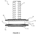
- the shaft may be fixed to the base 12 so that the base and threaded shaft turn together when adjusting the height of the supported object.
- the threaded shaft 11 may comprise a thread along its full length or part way along its length.
- the threaded shaft may have a threaded portion at an end of the shaft to engage a corresponding threaded socket part.
- the threaded shaft may comprise a hollow threaded portion. That is the threaded shaft may have an internal thread to mate with a corresponding threaded shaft or male thread.
- the foot 10 may comprise a threaded socket having an internal thread to mate with a corresponding threaded shaft attached to the object being supported. An example of a foot comprising a threaded socket is illustrated in Figure 25C .
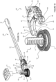
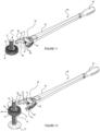
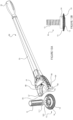
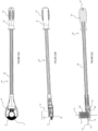
- a tool 50 is used for turning or rotating the foot to adjust the height of the object.
- the tool comprises a driving member 51.
- the foot comprises a corresponding driven member or feature 13.
- the driving member is a pinion 51 and the driven member or feature comprises a rotary rack 13 on (fixed to) the threaded shaft.
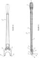
- the tool comprises a handle 52 coupled to the driving member 51 via a connecting rod 65 (shown in Figure 10 ).
- the rod coupled between the handle 52 and the driving member 51 is shrouded by an arm 53 extending between the driving member 51 and the handle 52. Rotation of the handle 52 about a longitudinal axis of the handle causes rotation of the driving member 51.
- the driving member 51 With the tool engaged with the foot the driving member 51 is engaged or meshed with the driven member 13 so that rotation of the handle turns the threaded shaft 11 for height adjustment.
- the driving member rotates about a lateral axis relative to a longitudinal axis of the threaded shaft when driving the driven member or feature 13.
- the driving member drives the driven member to rotate the driven member about the longitudinal axis of the leg.
- the lateral axis is substantially perpendicular to the longitudinal axis of the threaded shaft.
- the lateral axis is arranged at an angle to the longitudinal axis of the threaded shaft.
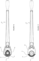
- the tool comprises a joint 54 between the handle 52 and the driving member 51 so that driving member 51 has a rotational axis able to articulate from a rotational axis of the handle 52.
- joint 54 is a universal joint.
- the articulation allows a user to move the handle up and down by rotation of the handle and arm about a substantially horizontal axis 55. This movement of the handle may ergonomically assist with use of the tool for height adjustment of the foot. Articulation between the handle and the driven member with the handle rotated about axis 55 to a raised position is illustrated in Figure 5 .
- the handle may be fitted with an interface for connecting an additional tool for applying torque to driving member via the handle.
- the illustrated embodiment as shown in Figure 8 comprises a hexagonal socket 61.
- a user may fit a tool such as a wrench or a power drill to the handle via the hexagonal socket to provide torque to the handle for turning the foot via the driving member. Whether a user turns the handle by hand or by a tool fitted to the handle may depend on the weight of the object being supported by the foot.
- the handle 52 and/or the interface 61 may be described as a torque input for applying torque to the driving member. The torque input allows a user to apply torque to the driving member, for example by hand using handle 52 wherein the handle is the torque input.
- the tool and the foot are complementarily adapted to releasably maintain engagement between the driving member 51 and the driven member or feature 13 to allow the driving member to drive the driven member or feature to rotate the shaft 11.
- the tool and the foot comprise complementary features to releasably maintain engagement between the driving member and the driven member when the tool is engaged with the foot.
- the tool and the foot comprise complementary features to releasably maintain engagement between the tool and the foot to releasably maintain engagement between the driving member and the driven member.
- the tool and the foot comprise complementary features to assist with alignment of the tool with the foot when engaging the tool to the foot.
- the foot 10 may be described as a coupling or coupling part of the height adjustable leg for coupling to the tool so that the tool is releasably engaged to the height adjustable leg for height adjustment.
- the tool comprises a lateral extension 56 for capturing or bearing against a lateral facing surface of the foot, for example surface 14.
- the tool comprises a lateral extension 56 for capturing or bearing against a lateral facing surface of the foot to releasably retain the tool to the foot in a lateral direction.
- the tool comprises two spaced apart lateral extensions 56.
- the lateral extensions 56 provide a jaw 63 for capturing the foot laterally to align the tool to the foot.
- radial facing surfaces 70 may bear against an outside diameter of the driven member or feature 13.
- the tool may comprise lateral extensions 56 for engaging an outer diameter of the threaded shaft.
- the tool lateral extensions 56 may engage the major diameter of the thread of the threaded shaft, the threaded shaft rotationally sliding on the radial facing surfaces 57 of the lateral extensions when the tool rotationally drives the foot.
- the foot may comprise a threaded socket and the lateral extensions may engage an outer diameter of the threaded socket.
- one or both lateral extensions may pivot between an open position to allow the tool to connect with the foot, and a closed position where the jaw of the tool grabs or closes around a diameter of the foot.
- each lateral extension may pivot about a vertical axis so that the jaw may present an open state to receive the foot. Once the foot is received in the jaw the lateral extensions are pivoted to close the jaw around the foot.
- the tool may be provided with an actuator to move the jaw between an open and close position.
- the actuator may comprise a rod that extends from the handle to the jaws of the tool and a mechanism to cause translational movement of the rod along the arm of the tool to rotate the lateral extensions between the open and close positions.
- the actuator preferably allows the jaw to be operated from the handle end of the tool.
- the jaw 63 formed by lateral extensions 56 may be described as being C shaped. In some embodiments the jaw extends around diameter 14 of the foot by 180 degrees or less than 180degrees, to capture the foot laterally to releasably retain the tool to the foot in a lateral direction to releasably maintain engagement between the driving member 51 and the driven member 13 as the driving member drives the driven member for height adjustment of the leg.
- the tool although laterally coupled or secured to the foot to maintain engagement between the driven and driving members, may be released from the foot by moving the tool laterally away from the foot in the direction of the arm of the tool. The tool is laterally coupled or secured to the foot in all other lateral directions.
- the tool comprises an axially facing bearing surface 58 and the foot comprises a corresponding axially facing bearing surface 15.
- contact between the tool and foot axial bearing surfaces 58, 15 releasably retain the tool to the foot in an axial direction to releasably maintain engagement between the driving member 52 and the driven member 13.
- contact between the axial bearing surfaces of the tool and foot holds the driving member against the driven member.
- the axial facing bearing surface 15 is provided by a flange 16 axially spaced from the driving member or feature 13. The tool is captured axially between the flange 16 and the driving member or feature 13 to axially align the position of the tool correctly to the foot for engagement between the driving member and the driven member.
- flange 66 may support the back or opposite side 19 of the driven member 13 to keep the driven member or feature 13 in contact with the driving member 51.
- the driven member 13 is captured between the lateral flange 66 of the tool and the driving member 51.
- flange 66 provides an axial facing bearing surface 68 to contact corresponding axial facing surface 19 of the foot to releasably maintain engagement between the driving member and the driven member or feature in an axial direction.
- the tool comprises a lateral member 56 that engages a circumferentially extending slot or channel 18 in the foot for axial positioning.
- the foot may comprise a disc or circular flange coaxial with the threaded shaft to be received in a corresponding recess or slot in the tool.
- the driven member or other flange may be received in a horizontal slot of the tool.
- a slot may be formed between surface 58 and flange 67 for receiving flange 16 of the foot 10.
- flanges 66 and 67 (best shown in Figure 10 ) of the tool may locate on surfaces 19 and 20 of the foot to position the tool relative to the foot in the axial direction.
- the tool flanges 66 and 67 provide a first axial facing bearing surface and a second opposite axial facing bearing surface to bear corresponding axial facing bearing surfaces 19 and 20 of the foot. Contact between the tool and foot axial facing bearing surfaces releasably retains the tool to the foot in an axial direction to releasably maintain engagement between the driving member and the driven member or feature.
- the driven member or feature 13 is fixed to or on the shaft 11 so that the driven member or feature remains at a fixed height relative to a floor surface or other surface on which the foot is to be positioned when the foot is supporting the weight of the object on the floor surface or other surface.
- the driven member may be integrally formed with the shaft, or may be attached to the shaft.
- the tool comprises a positioning feature or features for setting the driving member at a height relative to the floor surface or other surface so that the driving member is positioned axially relative to the foot for engagement with the driven member, the height of the driven member and height of the driving member both being referenced from the floor surface or other surface.
- the tool comprises guides 59 that contact the floor surface to present the tool at the correct height or axial position relative to the foot for engagement with the foot.
- the guides 59 or axial positioning features may provide an initial alignment of the tool to the foot.
- the tool may comprise ramp features 60 (best shown in Figure 10 ) to accommodate some vertical misalignment between the foot and the tool. For example, in a particular installation, prior to adjustment a foot may be raised off the floor surface so that correct axial positioning of the tool relative to the foot is not initially provided by guides 59. Guiding axial alignment between the tool and the foot and therefore between the driven member and the driving member is preferably provided by the ramp features bearing against an axial bearing surface of the foot.
- the ramps or cam surfaces 60 make sliding contact with the rotary rack to lift or guide the tool into correct axial position with the foot, even when the foot is initially raised slightly off the floor surface.
- the ramp or cam surface 60 provides axial alignment of distance X indicated on Figure 10 . If foot 10 was initially raised off the floor by distance X, with the tool supported on guides 59 on the floor, as a user pushes the tool into the foot, cam surface 60 will contact the foot and guide the tool to the correct axial position defined by axial facing surface 62.
- the ramp surface and the axial facing surface 62 are continuous.
- the threaded shaft is received in a threaded component 30 that is adapted to remain at a fixed height relative to the object being supported by the foot.
- the threaded component 30 is free to rotate relative to the object being supported.
- the threaded component 30 forms part of a foot assembly 10 or height adjustable leg assembly.
- the threaded shaft 11 is adapted to be rotationally fixed to the object being supported.
- the shaft may be provided with a flat longitudinal surface 17 or surfaces to mate with a socket (not illustrated) attached to or formed with the object supported by the foot, the socket comprising a corresponding flat surface or surfaces.
- a height adjustable leg assembly may comprise the shaft 11, corresponding socket (not shown) and the threaded component 30.
- the threaded component 30 comprises the driven member or feature 13, to be driven by the tool to adjust the relative axial positions of the threaded shaft and the threaded component.
- the threaded component may comprise a rotary rack 13 to be driven by the driving member 51 of the tool 50, as described above.
- the threaded component 30 may be described as a coupling or coupling part of the height adjustable leg for coupling to the tool so that the tool is releasably engaged to the height adjustable leg for height adjustment.
- the position of the threaded component 30 is not fixed relative to the floor surface or other surface supporting the base 12 of the foot.
- the threaded component raises or lowers with the supported object as the foot is adjusted by the tool for height adjustment.
- the tool 50 does not locate axially off the floor surface for initial alignment with the foot, as described for the embodiment of Figures 1A to 10 .
- Final axial and lateral alignment of the tool and the threaded component may be achieved in the same way as described with reference to the embodiment of Figures 1A to 10 .
- the foot 10 has been described above as comprising a threaded shaft 11.
- the driven member 13 may be integrally formed with the threaded shaft, or may be attached or releasably attached to the shaft.
- the foot may be provided without or separate to a threaded shaft 11.
- a height adjustable leg for supporting a cabinet, appliance or structure may comprise a threaded shaft 11, and a foot according to some embodiments of the present invention may be adapted to be attached, fixed or fitted to an end of the threaded shaft.
- a foot 10 according to some embodiments of the present invention may comprise the driven member 13 and an interface detail for fitting the foot 10 to a shaft 11.
- the interface feature is a socket.
- the foot comprises the socket 101 for receiving an end 111 of the threaded shaft to attach the foot to the end of the shaft.
- the shaft may form part of a height adjustable leg for supporting the cabinet, appliance or structure, and the foot is adapted to be fitted to the height adjustable leg.
- a height adjustable leg may comprise threaded shaft 11 and a threaded socket 5 or component adapted to be attached or fixed to the cabinet or structure or other object to be supported.
- the threaded component 30 may be called a foot.
- the foot 30 supports a cabinet or other object on the threaded shaft 11.
- the threaded shaft provides a leg on which the cabinet or object is supported via the foot 30.
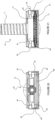
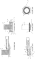
- the driven member 13 may be captured axially between the driving member 51 and the flange 66. In some embodiments the driven member may be captured between the flange 66 bearing against a back side 19 of the driven member and a second axial surface 62 (best illustrated in Figure 19 ) bearing against surfaces of the rotary rack 13 to axially locate the tool to the foot. Tooth tips of teeth of the rotary rack 13 may form a discontinuous annular axial facing bearing surface. In the embodiment of Figures 13A to 21 , the flange 66 provides a back support for the driven member 13.
- the driven member 13 With the tool engaged with the foot, the driven member 13 is captured between the lateral flange 66 of the tool and the driving member 51, or between the lateral flange 66 and the axial surface 62 bearing against the rotary rack.
- the flange 66 provides an axial facing bearing surface 68 to contact corresponding axial facing surface 19 of the foot to releasably maintain engagement between the driving member and the driven member or feature in an axial direction.
- the axial facing surface 19 of the foot may be a discontinuous surface.
- the back side of the driven member may comprise radial ribs for strength. The ribs may bear against the bearing surface 68 of the tool as the foot rotates when driven by the driving member of the tool.
- the tool comprises a first axial facing surface 68 and a second axial facing surface 62.
- first axial facing surface 68 of the tool may bear against the back side 19 of the driven member and the second axial facing surface 62 of the tool may bear against surfaces of the rotary rack 13 to axially locate the tool to the foot.
- the first and second axial facing surfaces 68, 62 face together to form sides of a slot or channel 80.
- the driven member 13 is received in the slot 80 and contacts the axial surfaces 68, 62 to position the tool axially to the foot.
- the surfaces 68, 62 each have a ramp surface 60 at an opening of the slot of channel to provide converging surfaces extending into the slot to assist with aligning the tool to the foot to ensure correct engagement between the rack and pinion.
- the tool comprises guides or sides 59 that contact the floor surface to present the tool at the correct height or axial position relative to the foot for engagement with the foot.
- the lateral extensions 56 may act as the guides, a bottom surface of the lateral extension 56 contacts the surface supporting the base of the foot to set the tool at an appropriate height to engage the foot.
- the guides 59 or axial positioning features may provide an initial alignment of the tool to the foot.
- the tool may comprise ramp features 60 (best shown in Figure 20 ) to accommodate some vertical misalignment between the foot and the tool.
- a foot may be raised off the floor surface so that correct axial positioning of the tool relative to the foot is not initially provided by guides 59.
- Guiding axial alignment between the tool and the foot and therefore between the driven member and the driving member is preferably provided by the ramp features bearing against an axial bearing surface of the foot.
- the ramps or cam surfaces 60 make sliding contact with the rotary rack to lift or guide the tool into correct axial position with the foot, even when the foot is initially raised slightly off the floor surface.
- the C shaped back support flange 66 may act as a lateral jaw to capture a diameter of the coupling to laterally position the tool to the foot from the base 12 of the foot, in a similar way to the way in which the jaw 63 formed by lateral extensions 56 fits around diameter 14 of the foot described with reference to the embodiment of Figures 1A to 10 .
- an upper jaw is provided by the lateral extensions 56 and a lower jaw is provided by the flange 66.
- a benefit of having two axially spaced jaws is that the jaws prevent twisting or bending of the foot, or prevent the tool twisting relative to the foot when driving the foot for height adjustment.
- the spacer may clip onto or over the base.
- an outer diameter or perimeter of the base may be received in an inner diameter of the spacer.
- the inventor has found that a spacer height of about 10mm to 15mm can be useful for use on a carpeted surface to assist with ensuring the foot is a suitable height for interfacing with the tool.
- a spacer may be useful where the foot is supporting an object from a floor surface below an adjacent surface level on which the tool may be positioned.
- a cabinet may be supported by a foot on a concrete floor. Adjacent to the cabinet the concrete floor may be covered with a floor overlay such as floor boards.
- the spacer may be used to raise the foot 10 by the thickness of the floor boards so that the tool positioned on the floor boards may reach the foot at the correct height.
- the spacer may have a height of about 10mm to 20mm.
- a range of spacers may be provided, each spacer of a different height to suit different floor surface softness or to account for a height difference between adjacent floor surfaces.
- a plurality of spacers may be provided in the height range of 5mm to 20mm.
- foot or threaded component 30 of Figure 12 and the foot 10 of Figure 13A each may be described as a coupling for releasably coupling the tool 50 to the leg to releasably maintain engagement between the driving member and the driven member.
- a height adjustable leg may comprise a threaded shaft 11, a corresponding threaded socket as described above (e.g. item 5 in Figure 1A ), and a coupling 10 fitted (fixed) to the threaded shaft part way along the threaded shaft 11 (for example a short distance from a bottom end of the threaded shaft) so that the coupling does not contact the floor surface supporting the object on the leg.
- An end or base of the threaded shaft may contact the floor surface to support the weight of the object being supported by the leg.
- the foot or coupling 10 comprises a driven member 13 integrally formed with a threaded socket 11.
- the threaded socket engages a threaded shaft (for example threaded shaft 5 shown in Figure 25C ) attached to the object being supported by the foot.
- the tool of Figures 25A to 25C comprises a handle 52 as a torque input and may also include a torque input 61 for engaging another tool as described earlier.
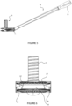
- the driving member 51 of the tool 50 and the torque input 52 are fixed together to rotate only on a lateral axis 115 relative to the longitudinal axis 116 of the leg. That is, in some embodiments as illustrated in Figures 25A to 25C , there is no articulation between the torque input 52, 61 and the driving member 51.
- the lateral axis is at an angle to the longitudinal axis of the leg when the driving member and driven member are engaged.
- the lateral axis 115 (which may be a longitudinal axis of the tool 50) is arranged at an angle to the longitudinal axis 116 of the leg.
- the longitudinal axis of the tool on which the driving member and torque input rotate is at an angle to the longitudinal axis of the leg.
- the lateral axis on which the driving member and torque input rotate is at an angle (100 in Figure 25C ) of 80 to 88 degrees, or 85 to 88 degrees, or 86 to 88 degrees, or 87 to 88 degrees. In a preferred embodiment the angle may be about 87.5 degrees.
- the tool comprises lateral extensions 56 to laterally engage with a diameter of the coupling 10.
- the tool laterally engages to an external diameter of threaded socket 11.
- the handle 52 has engagement features on an outside surface.
- the engagement features are longitudinal slots 110.
- the engagement features may be longitudinally extending ribs on an outer surface of the handle spaced apart around a circumference of the handle. In some embodiments there may be two or more ribs.
- the rotary rack has a width (distance between an outer radius and inner radius of the rack face) of about 5 to 20mm, or about 8 to 15mm, or about 10 to 12mm. In some embodiments the rack width is about 10mm.
- the pinion may have a length substantially similar to the width of the rotary rack.
- the pinion is fixed to the torque input without any articulation between the pinion and torque input.
- the pinion and rack are arranged so that the angle of the lateral axis on which the pinion rotates is at an angle such that the height of the handle or arm of the tool is less than the height of a typical toe-kick height of a cabinet when the tool is engaged to a foot at the rear of the cabinet and with the handle of the tool extending beyond the front of the cabinet.
- the pinion and rack are arranged so that the lateral axis of the pinion and torque input is less than about 12.5degrees so that the handle or arm of the tool clears the bottom of the cabinet.
- the tool is not limited to working in a particular arc length around the leg, but remains in a stationary angular position relative to the leg during height adjustment.
- rotation of the tool handle or other torque input about an axis independent of the longitudinal axis of the leg drives the driven member or feature for height adjustment of the leg.
- the tool may be used to adjust the leg in both directions without removing the tool from the coupling.
- the handle of the tool may be rotated in one direction (for example clockwise) to increase the height of the leg and then in the opposite direction (anti-clockwise) to reduce the height of the leg, while the tool remains continuously engaged to the leg.
- the driving member stays continuously engaged with the driven member to effect a change in height of the leg in both directions. This is particularly useful for fine tuning the height of a leg to achieve a level installation of a cabinet or other object. Where an adjustment in one direction overshoots a height level, adjustment in the opposite direction can be made immediately without removing the tool from the foot. This can be a significant advantage when adjusting the heights of many legs in a single installation, for example when installing kitchen cabinetry which often includes 30 or more legs. Typically some legs require adjustment upwards and others require adjustment downwards, requiring many changes in direction of adjustment. Likewise, there is no need to disengage a third party torque input such as a power drill, to change direction. When installing cabinetry having many legs for height adjustment, the speed and simplicity of adjustment provided by the tool and coupling of the present invention provides a substantial contribution to the art.
Landscapes
- Engineering & Computer Science (AREA)
- General Engineering & Computer Science (AREA)
- Mechanical Engineering (AREA)
- Textile Engineering (AREA)
- Legs For Furniture In General (AREA)
- Tables And Desks Characterized By Structural Shape (AREA)
- Workshop Equipment, Work Benches, Supports, Or Storage Means (AREA)
- Washing And Drying Of Tableware (AREA)
- Distribution Board (AREA)
- Beans For Foods Or Fodder (AREA)
- Pivots And Pivotal Connections (AREA)
Claims (10)
- Vorrichtung zum Einstellen eines höhenverstellbaren Beins zum Abstützen eines Schranks, wobei die Vorrichtung Folgendes umfasst:eine Kopplung (10, 30) zum Bilden eines Teils des höhenverstellbaren Beins, wobei die Kopplung (10, 30) ein Abtriebselement (13), undein Werkzeug (50), das ein Antriebselement (51) und einen Drehmomenteingang zum Anlegen eines Drehmoments an das Antriebselement (51) umfasst,wobei das Werkzeug (50) und die Kopplung (10, 30) komplementär ausgeführt sind, um Eingriff zwischen dem Antriebselement (51) und dem Abtriebselement (13) freigebbar aufrechtzuerhalten, um zu gestatten, dass das Antriebselement (51) das Abtriebselement (13) antreibt, damit sich die Kopplung (10, 30) um eine Längsachse des Beins zur Höheneinstellung des Beins dreht, undwobei das Antriebselement (51) und das Abtriebselement (13) Zahnräder sind, die lösbar miteinander kämmen, wenn das Werkzeug (50) mit der Kopplung (10, 30) in Eingriff gebracht ist,wobei das Werkzeug (50) angepasst ausgebildet ist, bezüglich des Beins in einer stationären Winkelposition zu bleiben, wenn das Antriebselement (51) das Abtriebselement (13) antreibt und wobei das Abtriebselement (13) und das Antriebselement (51) parallele Drehachsen haben, wenn das Zahnrad des Antriebselementes (51) und das Zahnrad des Abtriebselements (13) im Zahneingriff sind,gekennzeichnet durcheinen elektrischen Motor als Drehmomenteingang zum Antreiben des Antriebselements (51), wobei der Motor zwischen dem Handgriff (52) und dem Antriebselement (51) angeordnet ist.
- Vorrichtung nach Anspruch 1, wobei das Werkzeug und die Kopplung (10, 30) komplementär ausgeführt sind, so dass das Werkzeug aus irgendeiner lateralen Winkelrichtung bezüglich der Längsachse des Beins mit der Kopplung (10, 30) in Eingriff bringbar ist.
- Vorrichtung nach einem der vorhergehenden Ansprüche, wobei das Werkzeug (50) und die Kopplung (10, 30) dazu ausgeführt sind, kontinuierlich in Eingriff zu bleiben, wenn das Antriebselement (51) das Abtriebselement (13) zur Drehung um die Längsachse des Beins in beiden Richtungen antreibt, so dass die Richtung der Höheneinstellung des höhenverstellbaren Beins umgekehrt werden kann, ohne das Werkzeug (50) aus der Kopplung (10, 30) zu entfernen.
- Vorrichtung nach einem der vorhergehenden Ansprüche, wobei das Werkzeug (50) und die Kopplung (10, 30) komplementär ausgeführt sind, so dass das Werkzeug (50) beim Eingriff an der Kopplung (10, 30) an der Kopplung in einer axialen Richtung und/oder einer seitlichen Richtung festgelegt ist,
und/oder
wobei das Werkzeug (50) und die Kopplung (10, 30) komplementär ausgeführt sind, so dass das Werkzeug (50) beim Eingriff an der Kopplung (10, 30) an der Kopplung in beiden axialen Richtungen festgelegt ist. - Vorrichtung nach einem der vorherigen Ansprüche, wobei das Werkzeug (50) ausgeführt ist, entlang einer Fußbodenfläche zu gleiten, um zu jedem der Füße ausgerichtet zu werden, um mit dem Abtriebselement (13) der Kopplung (10, 30) in Eingriff bringbar zu sein und das Abtriebselement (13) anzutreiben, ohne dazu um eine Längsachse der Kopplung (10, 30) gedreht werden zu müssen.
- Werkzeug (50) zum Antreiben eines höhenverstellbaren Beins, das einen Schrank abstützt, umfassend:ein Antriebselement (51) und einen Drehmomenteingang zur Drehmomentübertragung an das Antriebselement (51),das Werkzeug (50), das dazu ausgeführt ist, einen Eingriff mit der Kopplung (10, 30) des höhenverstellbaren Beins, die das Abtriebselement (13) umfasst, freigebbar aufrechtzuerhalten, um zu gestatten, dass das Antriebselement (51) das Abtriebselement (13) zum Einstellen der Höhe des Schranks antreibt, undwobei das Antriebselement (51) ein Zahnrad ist, das dazu ausgeführt ist, lösbar mit dem Abtriebselement (13) der Kopplung (10, 30) zu kämmen,wobei das Werkzeug (50) dazu ausgeführt ist, bezüglich des höhenverstellbaren Beins in einer stationären Winkelposition zu bleiben, wenn das Antriebselement (51) das Abtriebselement (13) antreibt.wobei das Abtriebselement (13) und das Antriebselement (51) parallele Drehachsen haben, wenn das Zahnrad des Antriebselementes (51) und das Zahnrad des Abtriebselements (13) im Zahneingriff sind,durch gekennzeichnet,dass das Werkzeug (50) einen elektrischen Motor als Drehmomenteingang zum Antreiben des Antriebselements (51) umfasst, wobei der Motor zwischen dem Handgriff und dem Antriebselement (51) angeordnet ist.
- Werkzeug (50) nach Anspruch 6, wobei das Werkzeug (50) ausgeführt ist, mit der Kopplung (10, 30) aus irgendeiner lateralen Winkelrichtung bezüglich der Längsachse des Beins in Eingriff bringbar zu sein.
- Werkzeug (50) nach Anspruch 6 oder 7, wobei sich der Drehmomenteingang um eine Querachse bezüglich einer Drehachse des Beins dreht, wenn das Abtriebselement (13) angetrieben wird und/oder wobei sich der Drehmomenteingang auf einer Querachse dreht, die gegenüber der Längsachse des Beins angewinkelt ist, so dass der Drehmomenteingang beim Eingriff des Werkzeugs mit der Kopplung (10, 30) gegenüber einer Fußbodenfläche oder einer anderen Fläche, auf der das Bein beim Abstützen des Schrankes zu positionieren ist, angehoben ist.
- Werkzeug (50) nach einem der Ansprüche 6 bis 8, wobei das Werkzeug (50) ausgeführt ist, beim Eingriff an der Kopplung (10, 30) in Bezug auf die Kopplung in einer axialen Richtung und/oder einer seitlichen Richtung festlegbar zu sein,
und/oder
wobei das Werkzeug (50) ausgeführt ist, an der Kopplung (10, 30) in beiden axialen Richtungen festlegbar zu sein. - Werkzeug nach einem der Ansprüche 6 bis 9, wobei das Werkzeug (50) ausgeführt ist, entlang einer Fußbodenfläche zu gleiten, um jeden der Füße zu erreichen und dazu ausgerichtet zu werden, um mit dem Abtriebselement (13) der Kopplung (10, 30) in Eingriff bringbar zu sein und das Abtriebselement (13) anzutreiben, ohne dazu um eine Längsachse der Kopplung (10, 30) gedreht werden zu müssen.
Priority Applications (2)
| Application Number | Priority Date | Filing Date | Title |
|---|---|---|---|
| EP22183376.7A EP4089309A1 (de) | 2013-10-11 | 2014-10-08 | Schranknivelliervorrichtung |
| EP23191972.1A EP4276235A3 (de) | 2013-10-11 | 2014-10-08 | Schranknivelliervorrichtung |
Applications Claiming Priority (6)
| Application Number | Priority Date | Filing Date | Title |
|---|---|---|---|
| NZ61656613 | 2013-10-11 | ||
| NZ62306514 | 2014-03-27 | ||
| NZ62599414 | 2014-06-06 | ||
| NZ63167614 | 2014-09-12 | ||
| EP14815452.9A EP3055603B1 (de) | 2013-10-11 | 2014-10-08 | Schrankplanierungsvorrichtung |
| PCT/NZ2014/000215 WO2015053637A2 (en) | 2013-10-11 | 2014-10-08 | Cabinet levelling apparatus |
Related Parent Applications (1)
| Application Number | Title | Priority Date | Filing Date |
|---|---|---|---|
| EP14815452.9A Division EP3055603B1 (de) | 2013-10-11 | 2014-10-08 | Schrankplanierungsvorrichtung |
Related Child Applications (4)
| Application Number | Title | Priority Date | Filing Date |
|---|---|---|---|
| EP23191972.1A Division EP4276235A3 (de) | 2013-10-11 | 2014-10-08 | Schranknivelliervorrichtung |
| EP23191972.1A Division-Into EP4276235A3 (de) | 2013-10-11 | 2014-10-08 | Schranknivelliervorrichtung |
| EP22183376.7A Division-Into EP4089309A1 (de) | 2013-10-11 | 2014-10-08 | Schranknivelliervorrichtung |
| EP22183376.7A Division EP4089309A1 (de) | 2013-10-11 | 2014-10-08 | Schranknivelliervorrichtung |
Publications (3)
| Publication Number | Publication Date |
|---|---|
| EP3767151A1 EP3767151A1 (de) | 2021-01-20 |
| EP3767151C0 EP3767151C0 (de) | 2024-07-03 |
| EP3767151B1 true EP3767151B1 (de) | 2024-07-03 |
Family
ID=52130762
Family Applications (4)
| Application Number | Title | Priority Date | Filing Date |
|---|---|---|---|
| EP14815452.9A Active EP3055603B1 (de) | 2013-10-11 | 2014-10-08 | Schrankplanierungsvorrichtung |
| EP20194558.1A Active EP3767151B1 (de) | 2013-10-11 | 2014-10-08 | Schranknivelliervorrichtung |
| EP23191972.1A Pending EP4276235A3 (de) | 2013-10-11 | 2014-10-08 | Schranknivelliervorrichtung |
| EP22183376.7A Pending EP4089309A1 (de) | 2013-10-11 | 2014-10-08 | Schranknivelliervorrichtung |
Family Applications Before (1)
| Application Number | Title | Priority Date | Filing Date |
|---|---|---|---|
| EP14815452.9A Active EP3055603B1 (de) | 2013-10-11 | 2014-10-08 | Schrankplanierungsvorrichtung |
Family Applications After (2)
| Application Number | Title | Priority Date | Filing Date |
|---|---|---|---|
| EP23191972.1A Pending EP4276235A3 (de) | 2013-10-11 | 2014-10-08 | Schranknivelliervorrichtung |
| EP22183376.7A Pending EP4089309A1 (de) | 2013-10-11 | 2014-10-08 | Schranknivelliervorrichtung |
Country Status (17)
| Country | Link |
|---|---|
| US (2) | US10278500B2 (de) |
| EP (4) | EP3055603B1 (de) |
| KR (1) | KR20160067968A (de) |
| CN (1) | CN105793634B (de) |
| AU (1) | AU2014332598B2 (de) |
| CA (2) | CA3284725A1 (de) |
| DE (3) | DE202014011343U1 (de) |
| DK (1) | DK3055603T3 (de) |
| ES (1) | ES2844675T3 (de) |
| HR (1) | HRP20201624T1 (de) |
| HU (1) | HUE051378T2 (de) |
| PL (1) | PL3055603T3 (de) |
| PT (1) | PT3055603T (de) |
| RS (1) | RS61130B1 (de) |
| SI (1) | SI3055603T1 (de) |
| WO (1) | WO2015053637A2 (de) |
| ZA (1) | ZA201603168B (de) |
Families Citing this family (34)
| Publication number | Priority date | Publication date | Assignee | Title |
|---|---|---|---|---|
| PL3055603T3 (pl) * | 2013-10-11 | 2021-01-25 | Designerscope Limited | Urządzenie do poziomowania szafki |
| US9993911B1 (en) * | 2014-01-13 | 2018-06-12 | Anthony Santangelo | Wrench system; side loading, insert using, ratcheting, open end, pass through, socket, quick changing, fastener retaining, reversible, manual or powered, variable high speed, torque sensing, flare nut |
| USD796882S1 (en) * | 2014-03-28 | 2017-09-12 | Designerscope Limited | Supporting foot for cabinetry or furniture |
| CA158900S (en) * | 2014-03-28 | 2015-07-17 | Designerscope Ltd | Wrench |
| GB201501629D0 (en) * | 2015-01-31 | 2015-03-18 | Bunday Nick | A device suitable to rotate a height-adjustable furniture leg |
| ITUB20153365A1 (it) | 2015-09-03 | 2017-03-03 | Scilm Spa | Attrezzatura per la regolazione di piedi di supporto per mobili rispetto ad un piano di appoggio e dispositivo di supporto per mobili rispetto ad un piano di appoggio |
| EP3232861B1 (de) | 2016-03-11 | 2020-07-29 | LEONARDO S.r.l. | Kompaktes verbindungs- und ausgleichssystem für teile von möbeln und einrichtungsgegenständen |
| ITUA20161574A1 (it) * | 2016-03-11 | 2017-09-11 | Leonardo Srl | Sistema compatto di giunzione e livellatura per parti di mobili e articoli da arredamento |
| ITUA20162492A1 (it) * | 2016-04-11 | 2017-10-11 | Volpato Ind S P A | Complesso di elementi per la regolazione dell’orizzontalità di un mobile o simili. |
| IT201600070803A1 (it) * | 2016-07-07 | 2018-01-07 | Leonardo Srl | Sistema di giunzione ad azionamento frontale in asse con un fondo di mobili e articoli da arredamento |
| IT201600102943A1 (it) * | 2016-10-13 | 2018-04-13 | Leonardo Srl | Sistema di piedino per parti di mobili e articoli da arredamento con livellatura a regolazione frontale |
| US10376129B2 (en) * | 2016-11-08 | 2019-08-13 | Whirlpool Corporation | Dishwasher leveling assembly |
| CN109247894B (zh) * | 2017-07-14 | 2023-01-03 | 青岛海尔洗碗机有限公司 | 一种底角支撑结构及洗碗机 |
| US10625402B2 (en) * | 2017-07-24 | 2020-04-21 | Michael Thomas Jensen | Ratcheting spanner |
| US11786035B2 (en) * | 2017-09-04 | 2023-10-17 | Designerscope Limited | Cabinet levelling apparatus |
| IT201700111868U1 (it) * | 2017-10-05 | 2019-04-05 | Leonardo Srl | Combinazione chiave-piede per il livellamento di mobili |
| EP3727094A4 (de) * | 2017-12-19 | 2021-09-22 | Justin Bernard Mulligan | Schrankbein und verstellwerkzeug |
| CN108118497B (zh) * | 2018-01-04 | 2020-05-19 | 无锡小天鹅电器有限公司 | 调节结构和洗衣机 |
| CN108049123B (zh) * | 2018-01-04 | 2020-05-19 | 无锡小天鹅电器有限公司 | 底脚结构和家用电器 |
| ES2930137T3 (es) * | 2018-09-19 | 2022-12-07 | Leonardo Srl | Pata telescópica para muebles y/o artículos de mobiliario con montaje simplificado y sistema que usa dicha pata |
| DE202018005252U1 (de) * | 2018-11-02 | 2018-12-13 | Tekin Dalgic | Werkzeuge zur Höhenverstellung von zylinderförmigen oder kegelstumpfförmigenSockelfüßen |
| DE102018221159A1 (de) * | 2018-12-06 | 2020-06-10 | BSH Hausgeräte GmbH | Haushaltsgerät |
| TWI689383B (zh) | 2019-04-16 | 2020-04-01 | 優鋼機械股份有限公司 | 高強度扳手 |
| DE202019105005U1 (de) | 2019-09-10 | 2019-10-22 | Kunststoff Kommanditgesellschaft Nehl & Co | Verstellwerkzeug für Verstellteile von insbesondere Sockelfüßen für Möbel |
| PL3738472T3 (pl) | 2019-05-13 | 2022-04-04 | Kunststoff Kommanditgesellschaft Nehl & Co | Narzędzie regulujące do części przestawnych zwłaszcza stopek cokołowych mebli |
| CN110393380B (zh) * | 2019-07-16 | 2022-01-04 | 佛山市顺德区美的洗涤电器制造有限公司 | 集成式厨房电器及其安装方法 |
| CN111503436B (zh) * | 2020-04-23 | 2021-11-09 | 苏州浪潮智能科技有限公司 | 一种调平装置及系统 |
| US12397397B2 (en) * | 2020-05-11 | 2025-08-26 | Leonardo S.R.L. | Tool for adjusting shaped profile feet for furniture items |
| USD968204S1 (en) * | 2020-06-30 | 2022-11-01 | Häfele SE & Co KG | Foot for adjustable cabinet leg |
| USD955209S1 (en) * | 2020-06-30 | 2022-06-21 | Designerscope Limited | Foot for adjustable cabinet leg |
| WO2022003576A1 (en) * | 2020-06-30 | 2022-01-06 | Designerscope Limited | Cabinet levelling foot |
| US11873874B2 (en) * | 2021-10-26 | 2024-01-16 | Bernard J. Carr | Adjustable shock absorber system and device |
| US20240116322A1 (en) * | 2021-10-26 | 2024-04-11 | Bernard J. Carr | Adjustable shock absorber system and device |
| US11878562B2 (en) * | 2021-10-26 | 2024-01-23 | Bernard J. Carr | Adjustable shock absorber system and device |
Citations (17)
| Publication number | Priority date | Publication date | Assignee | Title |
|---|---|---|---|---|
| DE2609941A1 (de) | 1975-06-16 | 1976-12-30 | Edward Dorma | Kraftwerkzeug |
| JPH09206147A (ja) | 1996-02-06 | 1997-08-12 | Takigen Mfg Co Ltd | 機器の調節脚の回転操作具 |
| EP0904899A2 (de) | 1997-09-24 | 1999-03-31 | CAZZANIGA S.p.A. | Werkzeug zum Anziehen/Lösen von Muttern deren äussere Oberfläche mit Zähnen versehenen sind |
| JPH11188653A (ja) | 1997-12-25 | 1999-07-13 | Shibaura Mechatronics Corp | 管用ねじ締結機 |
| JPH11270515A (ja) * | 1998-03-19 | 1999-10-05 | Hitachi Koki Co Ltd | 機器の高さ調整工具 |
| DE10221874A1 (de) | 2001-06-29 | 2003-01-23 | Bernd Auer | Vorrichtung zum Drehen eines Montageelementes |
| EP1313180A2 (de) | 2001-11-20 | 2003-05-21 | Black & Decker Inc. | Elektrischer Verbinder für Elektrowerkzeug |
| CN2785454Y (zh) | 2004-09-10 | 2006-06-07 | 上海芬妮尔塑料制品有限公司 | 塑料调整脚 |
| US7263917B1 (en) | 2006-07-25 | 2007-09-04 | International Business Machines Corporation | Open-ended spin tool |
| JP2008213058A (ja) | 2007-03-01 | 2008-09-18 | Takigen Mfg Co Ltd | 機器の調節脚の回転操作具 |
| US7500412B1 (en) | 2005-11-21 | 2009-03-10 | The United States Of America As Represented By The Secretary Of The Navy | Speed nut and drive gear assembly |
| NZ574230A (en) | 2008-05-09 | 2010-05-28 | Robert William Wise | Cordless motor assisted torque wrench |
| FR2956893A1 (fr) | 2010-02-26 | 2011-09-02 | Peugeot Citroen Automobiles Sa | Dispositif de connexion d'un conduit de fluide sur un boitier, moyen de fixation, organe de vissage et procede de vissage d'un moyen de fixation sur un boitier par l'intermediaire d'un organe de vissage |
| JP4865441B2 (ja) | 2006-08-01 | 2012-02-01 | タキゲン製造株式会社 | 機器の調整脚の回転操作具 |
| ITRE20100070A1 (it) | 2010-09-13 | 2012-03-14 | Casarini Srl | Gruppo per l'avvitamento di corpi filettati |
| US20120297939A1 (en) | 2011-05-23 | 2012-11-29 | Joseph Spata | Handle-Driven Torque Transfer Wrench having Pivotable Head |
| US20140083255A1 (en) | 2012-09-22 | 2014-03-27 | Kauffman Tools Llc | Universal self-adjusting, open-ended powered wrench |
Family Cites Families (45)
| Publication number | Priority date | Publication date | Assignee | Title |
|---|---|---|---|---|
| US809078A (en) | 1904-11-18 | 1906-01-02 | Charles Dwight Seymour | Adjustable leg for billiard-tables. |
| US1073294A (en) * | 1911-04-06 | 1913-09-16 | Alexander Siewert | Extension and retraction device. |
| US1632383A (en) * | 1926-04-09 | 1927-06-14 | Seiden Samuel | Leveling device |
| US2512068A (en) * | 1946-06-12 | 1950-06-20 | Ruby G Mayo | Dressmaker's pedestal |
| US2828578A (en) * | 1955-09-14 | 1958-04-01 | William M Miller | Combination caster and leveller for appliances |
| US2906153A (en) * | 1958-04-28 | 1959-09-29 | Edward A Erb | Gear-operated socket wrench |
| IT1028020B (it) | 1974-12-23 | 1979-01-30 | Camar Di Cattaneo | Piedino per mobili |
| IT1028019B (it) | 1974-12-23 | 1979-01-30 | Camar Di Cattaneo | Livellatore per mobili e metodo per la sua fabbricazione |
| DE7734870U1 (de) | 1977-11-14 | 1978-03-02 | Kunststoff Kg Nehl & Co, 4980 Buende | Hoehenverstellbarer moebelstuetzfuss |
| IT7822940U1 (it) | 1978-10-03 | 1980-04-03 | Camar Di Cattaneo & Marzorati S N C | Piedino per mobili con livellatore incorporato |
| DE3884668T2 (de) | 1987-05-20 | 1994-05-05 | Canon Kk | Bilderzeugungsgerät. |
| DE3717524A1 (de) * | 1987-05-25 | 1988-12-15 | Unterholzner Innenausbau Ohg G | Einbaubeschlag zum verbinden oder ausrichten von inneneinrichtungselementen |
| JPH067345B2 (ja) | 1987-06-24 | 1994-01-26 | 株式会社 エイ・ティ・ア−ル自動翻訳電話研究所 | ベクトル量子化を用いた音声認識方式 |
| IT1232959B (it) | 1987-11-13 | 1992-03-11 | Camar Spa | Piedino abbattibile per mobili. |
| JPH026147A (ja) | 1988-06-25 | 1990-01-10 | Nec Corp | インパクトドット式印字ヘッド |
| US4991805A (en) | 1989-05-17 | 1991-02-12 | Whirlpool Corporation | Refrigerator gear driven leveling system |
| DE8908536U1 (de) | 1989-07-13 | 1989-09-14 | Huwil-Werke GmbH Möbelschloß- und Beschlagfabriken, 5207 Ruppichteroth | Höhenversteller für Möbel |
| IT1249605B (it) | 1991-02-26 | 1995-03-09 | Camar Spa | Dispositivo livellatore in particolare per mobili |
| US5709136A (en) * | 1996-02-25 | 1998-01-20 | Mcdonnell Douglas Corporation | Power driven tools |
| US5967472A (en) * | 1997-04-03 | 1999-10-19 | Bsh Bosch Und Siemens Hausgeraete Gmbh | Height-adjusting device for an adjusting foot of a household appliance |
| US6135401A (en) * | 1998-12-23 | 2000-10-24 | Chen; Shi-Jia | Tool for supporting objects |
| US6279860B1 (en) * | 1999-09-07 | 2001-08-28 | Brett A. Swanger | Heat exchanger housing support |
| DE20000358U1 (de) | 2000-01-11 | 2001-05-23 | Paul Henke GmbH & Co KG, 32584 Löhne | Höhenverstellbarer Sockelfuss für Möbel |
| DE10124092A1 (de) | 2001-05-16 | 2003-01-02 | Ketterer Soehne Gmbh & Co Kg B | Getriebe für eine Möbelbein-Höhenverstellung |
| US6729590B2 (en) * | 2002-01-23 | 2004-05-04 | Edward Gabriel | Leveling device |
| US6910665B2 (en) * | 2003-03-12 | 2005-06-28 | Maytag Corporation | Integrated refrigerator cabinet leveling and door closing assembly |
| KR100662301B1 (ko) * | 2003-05-20 | 2007-01-02 | 엘지전자 주식회사 | 가전제품용 레그 록너트 |
| WO2004104471A1 (en) * | 2003-05-20 | 2004-12-02 | Lg Electronics Inc. | Lock nut and wrench for leg assembly of home appliance |
| DE102004022681B3 (de) | 2004-05-05 | 2005-09-22 | Miele & Cie. Kg | Höhenverstellbarer Fuß für Hausgeräte, wie Wasch- oder Geschirrspülgerät mit einem Schaft der standseitig mit einem Fußteller bestückt ist |
| DE102004050362A1 (de) * | 2004-10-15 | 2006-04-27 | BSH Bosch und Siemens Hausgeräte GmbH | Verstellvorrichtung, insbesondere für einen Stellfuß eines Haushaltsgeräts |
| US7293484B2 (en) | 2005-01-24 | 2007-11-13 | Kuo-Chen Liu | Opener head retainer |
| US7762158B2 (en) * | 2006-11-18 | 2010-07-27 | Hiwin Technologies Corp. | Self-locking device for a table elevating screw |
| KR101359871B1 (ko) * | 2006-12-20 | 2014-02-07 | 엘지전자 주식회사 | 가전 기기 및 가전 기기의 높이 조절 장치 |
| ITMI20072089A1 (it) | 2007-10-30 | 2009-04-30 | Leonardo Srl | Dispositivo livellatore perfezionato. |
| CN201303926Y (zh) * | 2008-11-03 | 2009-09-09 | 美的集团有限公司 | 嵌入式洗碗机的高度调节机构 |
| IT1392975B1 (it) | 2009-02-17 | 2012-04-02 | Illinois Tool Works | Piedino regolabile, in particolare un piedino posteriore, per un elettrodomestico |
| DE102010027834B4 (de) * | 2010-04-15 | 2012-12-06 | Sven Hunze | Justierwerkzeug |
| CN102654724B (zh) | 2011-03-01 | 2014-10-15 | 中强光电股份有限公司 | 投影机及其升降模组 |
| TR201103077A2 (tr) * | 2011-03-31 | 2012-10-22 | Bsh Ev Aletler� San. Ve T�C. A.�. | Bir ankastre ev aleti. |
| US20120280607A1 (en) * | 2011-05-04 | 2012-11-08 | Doberstein Andrew J | Appliance With Frontal Installation Adjustment |
| CN202140751U (zh) * | 2011-06-23 | 2012-02-08 | 王吴光 | 一种机械驱动调节机床垫脚板高度的装置 |
| CN203023749U (zh) | 2012-12-25 | 2013-06-26 | 上海亚泽金属屋面系统股份有限公司 | 一种用于现场生产流水线设备的快速调平装置 |
| PL3055603T3 (pl) | 2013-10-11 | 2021-01-25 | Designerscope Limited | Urządzenie do poziomowania szafki |
| CA158900S (en) * | 2014-03-28 | 2015-07-17 | Designerscope Ltd | Wrench |
| USD796882S1 (en) * | 2014-03-28 | 2017-09-12 | Designerscope Limited | Supporting foot for cabinetry or furniture |
-
2014
- 2014-10-08 PL PL14815452T patent/PL3055603T3/pl unknown
- 2014-10-08 US US15/028,295 patent/US10278500B2/en active Active
- 2014-10-08 DE DE202014011343.2U patent/DE202014011343U1/de not_active Expired - Lifetime
- 2014-10-08 EP EP14815452.9A patent/EP3055603B1/de active Active
- 2014-10-08 EP EP20194558.1A patent/EP3767151B1/de active Active
- 2014-10-08 EP EP23191972.1A patent/EP4276235A3/de active Pending
- 2014-10-08 EP EP22183376.7A patent/EP4089309A1/de active Pending
- 2014-10-08 CA CA3284725A patent/CA3284725A1/en active Pending
- 2014-10-08 ES ES14815452T patent/ES2844675T3/es active Active
- 2014-10-08 DK DK14815452.9T patent/DK3055603T3/da active
- 2014-10-08 RS RS20201422A patent/RS61130B1/sr unknown
- 2014-10-08 CA CA2927112A patent/CA2927112A1/en active Pending
- 2014-10-08 PT PT148154529T patent/PT3055603T/pt unknown
- 2014-10-08 HR HRP20201624TT patent/HRP20201624T1/hr unknown
- 2014-10-08 AU AU2014332598A patent/AU2014332598B2/en active Active
- 2014-10-08 KR KR1020167012198A patent/KR20160067968A/ko not_active Ceased
- 2014-10-08 DE DE202014011606.7U patent/DE202014011606U1/de not_active Expired - Lifetime
- 2014-10-08 CN CN201480064915.7A patent/CN105793634B/zh active Active
- 2014-10-08 HU HUE14815452A patent/HUE051378T2/hu unknown
- 2014-10-08 DE DE202014011517.6U patent/DE202014011517U1/de not_active Expired - Lifetime
- 2014-10-08 SI SI201431721T patent/SI3055603T1/sl unknown
- 2014-10-08 WO PCT/NZ2014/000215 patent/WO2015053637A2/en not_active Ceased
-
2016
- 2016-05-11 ZA ZA2016/03168A patent/ZA201603168B/en unknown
-
2019
- 2019-03-28 US US16/368,215 patent/US10765209B2/en active Active
Patent Citations (17)
| Publication number | Priority date | Publication date | Assignee | Title |
|---|---|---|---|---|
| DE2609941A1 (de) | 1975-06-16 | 1976-12-30 | Edward Dorma | Kraftwerkzeug |
| JPH09206147A (ja) | 1996-02-06 | 1997-08-12 | Takigen Mfg Co Ltd | 機器の調節脚の回転操作具 |
| EP0904899A2 (de) | 1997-09-24 | 1999-03-31 | CAZZANIGA S.p.A. | Werkzeug zum Anziehen/Lösen von Muttern deren äussere Oberfläche mit Zähnen versehenen sind |
| JPH11188653A (ja) | 1997-12-25 | 1999-07-13 | Shibaura Mechatronics Corp | 管用ねじ締結機 |
| JPH11270515A (ja) * | 1998-03-19 | 1999-10-05 | Hitachi Koki Co Ltd | 機器の高さ調整工具 |
| DE10221874A1 (de) | 2001-06-29 | 2003-01-23 | Bernd Auer | Vorrichtung zum Drehen eines Montageelementes |
| EP1313180A2 (de) | 2001-11-20 | 2003-05-21 | Black & Decker Inc. | Elektrischer Verbinder für Elektrowerkzeug |
| CN2785454Y (zh) | 2004-09-10 | 2006-06-07 | 上海芬妮尔塑料制品有限公司 | 塑料调整脚 |
| US7500412B1 (en) | 2005-11-21 | 2009-03-10 | The United States Of America As Represented By The Secretary Of The Navy | Speed nut and drive gear assembly |
| US7263917B1 (en) | 2006-07-25 | 2007-09-04 | International Business Machines Corporation | Open-ended spin tool |
| JP4865441B2 (ja) | 2006-08-01 | 2012-02-01 | タキゲン製造株式会社 | 機器の調整脚の回転操作具 |
| JP2008213058A (ja) | 2007-03-01 | 2008-09-18 | Takigen Mfg Co Ltd | 機器の調節脚の回転操作具 |
| NZ574230A (en) | 2008-05-09 | 2010-05-28 | Robert William Wise | Cordless motor assisted torque wrench |
| FR2956893A1 (fr) | 2010-02-26 | 2011-09-02 | Peugeot Citroen Automobiles Sa | Dispositif de connexion d'un conduit de fluide sur un boitier, moyen de fixation, organe de vissage et procede de vissage d'un moyen de fixation sur un boitier par l'intermediaire d'un organe de vissage |
| ITRE20100070A1 (it) | 2010-09-13 | 2012-03-14 | Casarini Srl | Gruppo per l'avvitamento di corpi filettati |
| US20120297939A1 (en) | 2011-05-23 | 2012-11-29 | Joseph Spata | Handle-Driven Torque Transfer Wrench having Pivotable Head |
| US20140083255A1 (en) | 2012-09-22 | 2014-03-27 | Kauffman Tools Llc | Universal self-adjusting, open-ended powered wrench |
Non-Patent Citations (7)
| Title |
|---|
| ANONYM: "Das endgültige Aus für Fennel", 28 December 2010 (2010-12-28), XP093199156, Retrieved from the Internet <URL:https://www.nw.de/lokal/kreis_minden_luebbecke/bad_oeynhausen/4127635_Das-endgueltige-Aus-fuer-Fennel.html> |
| ANONYM: "Mobeltechnik '83 - Aktuelle Erganzung des Nehl-Hauptkataloges", PRODUKTKATALOG FIRMA NEHL, 1 January 1983 (1983-01-01), pages 1 - 9, XP093199161 |
| ANONYMOUS: "Innovative Design-Ideen fur's Buro", FENNEL OFFICE EQUIPMENT BROCHURE, 25 October 2011 (2011-10-25), XP093199147, Retrieved from the Internet <URL:http://web.archive.org/web/20111025111540/http://www.fennel.de/uploads/media/fennel_office_equipment.pdf> |
| ANONYMOUS: "Zahnrad ", WIKIPEDIA (ACCESSED VIA THE WAYBACK MACHINE), 9 May 2013 (2013-05-09), XP093269988, Retrieved from the Internet <URL:https://web.archive.org/web/20130509052405/http://de.wikipedia.org/wiki/Zahnrad> |
| D17.1 - SCREENSHOT DER WEBPAGE WWW.FENNEL.DE DER FENNEL GMBH & CO. KG VOM 25. OKTOBER 2011 |
| D17.2 - VON DER WEBPAGE HTTPS://SLIDEPLAYER.ORG/SLIDE/3385837/ HERUNTERGELADENE POWERPOINT PRÄSENTATION ZU DEM PRODUKT „SOCKELFUSSSYSTEM MULTI-STAR-VARIO" |
| D17.2.1 - SCREENSHOT FENSTER MIT DETAILINFORMATIONEN |
Also Published As
Similar Documents
| Publication | Publication Date | Title |
|---|---|---|
| EP3767151B1 (de) | Schranknivelliervorrichtung | |
| US11786035B2 (en) | Cabinet levelling apparatus | |
| US10655388B2 (en) | Adjustable internal double limit stop for roller shades | |
| AU2017253848B2 (en) | Sliding-door system | |
| EP2675593B1 (de) | Vorrichtung zum anziehen von befestigungsschrauben | |
| US20110271498A1 (en) | Framing or Deck Board Clamp | |
| HK1225782A1 (en) | Cabinet levelling apparatus | |
| CN102121348B (zh) | 弹簧张力的调节 | |
| WO2022003576A1 (en) | Cabinet levelling foot | |
| EP3705646B1 (de) | Urinalbefestigungsanordnung | |
| CN118003275B (zh) | 一种用于幕墙安装的螺栓安装装置 | |
| CN210598109U (zh) | 一种建筑钢构脚手架装置 | |
| CN101263274B (zh) | 弹簧张力 | |
| AU2011235923A1 (en) | Framing or deck board clamp | |
| JP2017064047A (ja) | 洗面台 |
Legal Events
| Date | Code | Title | Description |
|---|---|---|---|
| PUAI | Public reference made under article 153(3) epc to a published international application that has entered the european phase |
Free format text: ORIGINAL CODE: 0009012 |
|
| STAA | Information on the status of an ep patent application or granted ep patent |
Free format text: STATUS: THE APPLICATION HAS BEEN PUBLISHED |
|
| AC | Divisional application: reference to earlier application |
Ref document number: 3055603 Country of ref document: EP Kind code of ref document: P |
|
| AK | Designated contracting states |
Kind code of ref document: A1 Designated state(s): AL AT BE BG CH CY CZ DE DK EE ES FI FR GB GR HR HU IE IS IT LI LT LU LV MC MK MT NL NO PL PT RO RS SE SI SK SM TR |
|
| STAA | Information on the status of an ep patent application or granted ep patent |
Free format text: STATUS: REQUEST FOR EXAMINATION WAS MADE |
|
| 17P | Request for examination filed |
Effective date: 20210720 |
|
| RBV | Designated contracting states (corrected) |
Designated state(s): AL AT BE BG CH CY CZ DE DK EE ES FI FR GB GR HR HU IE IS IT LI LT LU LV MC MK MT NL NO PL PT RO RS SE SI SK SM TR |
|
| RAP1 | Party data changed (applicant data changed or rights of an application transferred) |
Owner name: HAEFELE SE & CO KG |
|
| STAA | Information on the status of an ep patent application or granted ep patent |
Free format text: STATUS: EXAMINATION IS IN PROGRESS |
|
| 17Q | First examination report despatched |
Effective date: 20230310 |
|
| P01 | Opt-out of the competence of the unified patent court (upc) registered |
Effective date: 20230524 |
|
| TPAC | Observations filed by third parties |
Free format text: ORIGINAL CODE: EPIDOSNTIPA |
|
| GRAP | Despatch of communication of intention to grant a patent |
Free format text: ORIGINAL CODE: EPIDOSNIGR1 |
|
| STAA | Information on the status of an ep patent application or granted ep patent |
Free format text: STATUS: GRANT OF PATENT IS INTENDED |
|
| INTG | Intention to grant announced |
Effective date: 20240115 |
|
| GRAJ | Information related to disapproval of communication of intention to grant by the applicant or resumption of examination proceedings by the epo deleted |
Free format text: ORIGINAL CODE: EPIDOSDIGR1 |
|
| STAA | Information on the status of an ep patent application or granted ep patent |
Free format text: STATUS: EXAMINATION IS IN PROGRESS |
|
| GRAP | Despatch of communication of intention to grant a patent |
Free format text: ORIGINAL CODE: EPIDOSNIGR1 |
|
| STAA | Information on the status of an ep patent application or granted ep patent |
Free format text: STATUS: GRANT OF PATENT IS INTENDED |
|
| INTC | Intention to grant announced (deleted) | ||
| INTG | Intention to grant announced |
Effective date: 20240328 |
|
| GRAS | Grant fee paid |
Free format text: ORIGINAL CODE: EPIDOSNIGR3 |
|
| GRAA | (expected) grant |
Free format text: ORIGINAL CODE: 0009210 |
|
| STAA | Information on the status of an ep patent application or granted ep patent |
Free format text: STATUS: THE PATENT HAS BEEN GRANTED |
|
| AC | Divisional application: reference to earlier application |
Ref document number: 3055603 Country of ref document: EP Kind code of ref document: P |
|
| AK | Designated contracting states |
Kind code of ref document: B1 Designated state(s): AL AT BE BG CH CY CZ DE DK EE ES FI FR GB GR HR HU IE IS IT LI LT LU LV MC MK MT NL NO PL PT RO RS SE SI SK SM TR |
|
| REG | Reference to a national code |
Ref country code: DE Ref legal event code: R026 Ref document number: 602014090463 Country of ref document: DE |
|
| PLBI | Opposition filed |
Free format text: ORIGINAL CODE: 0009260 |
|
| REG | Reference to a national code |
Ref country code: CH Ref legal event code: EP |
|
| REG | Reference to a national code |
Ref country code: DE Ref legal event code: R096 Ref document number: 602014090463 Country of ref document: DE |
|
| U01 | Request for unitary effect filed |
Effective date: 20240703 |
|
| 26 | Opposition filed |
Opponent name: ADOLF WUERTH GMBH & CO. KG Effective date: 20240705 |
|
| P04 | Withdrawal of opt-out of the competence of the unified patent court (upc) registered |
Free format text: CASE NUMBER: APP_40729/2024 Effective date: 20240709 |
|
| U07 | Unitary effect registered |
Designated state(s): AT BE BG DE DK EE FI FR IT LT LU LV MT NL PT SE SI Effective date: 20240712 |
|
| REG | Reference to a national code |
Ref country code: DE Ref legal event code: R039 Ref document number: 602014090463 Country of ref document: DE |
|
| U30 | Action lodged before the upc [information provided by the upc] |
Free format text: ACTION-TYPE: REVOCATION ACTION; CASE-NUMBER: ACT_51553/2024 Effective date: 20240912 |
|
| U20 | Renewal fee for the european patent with unitary effect paid |
Year of fee payment: 11 Effective date: 20241028 |
|
| P05 | Withdrawal of opt-out of the competence of the unified patent court (upc) changed |
Free format text: CASE NUMBER: APP_40729/2024 Effective date: 20240712 |
|
| PG25 | Lapsed in a contracting state [announced via postgrant information from national office to epo] |
Ref country code: NO Free format text: LAPSE BECAUSE OF FAILURE TO SUBMIT A TRANSLATION OF THE DESCRIPTION OR TO PAY THE FEE WITHIN THE PRESCRIBED TIME-LIMIT Effective date: 20241003 |
|
| PG25 | Lapsed in a contracting state [announced via postgrant information from national office to epo] |
Ref country code: GR Free format text: LAPSE BECAUSE OF FAILURE TO SUBMIT A TRANSLATION OF THE DESCRIPTION OR TO PAY THE FEE WITHIN THE PRESCRIBED TIME-LIMIT Effective date: 20241004 Ref country code: PL Free format text: LAPSE BECAUSE OF FAILURE TO SUBMIT A TRANSLATION OF THE DESCRIPTION OR TO PAY THE FEE WITHIN THE PRESCRIBED TIME-LIMIT Effective date: 20240703 |
|
| PG25 | Lapsed in a contracting state [announced via postgrant information from national office to epo] |
Ref country code: IS Free format text: LAPSE BECAUSE OF FAILURE TO SUBMIT A TRANSLATION OF THE DESCRIPTION OR TO PAY THE FEE WITHIN THE PRESCRIBED TIME-LIMIT Effective date: 20241103 |
|
| PG25 | Lapsed in a contracting state [announced via postgrant information from national office to epo] |
Ref country code: CZ Free format text: LAPSE BECAUSE OF FAILURE TO SUBMIT A TRANSLATION OF THE DESCRIPTION OR TO PAY THE FEE WITHIN THE PRESCRIBED TIME-LIMIT Effective date: 20240703 Ref country code: HR Free format text: LAPSE BECAUSE OF FAILURE TO SUBMIT A TRANSLATION OF THE DESCRIPTION OR TO PAY THE FEE WITHIN THE PRESCRIBED TIME-LIMIT Effective date: 20240703 |
|
| PG25 | Lapsed in a contracting state [announced via postgrant information from national office to epo] |
Ref country code: ES Free format text: LAPSE BECAUSE OF FAILURE TO SUBMIT A TRANSLATION OF THE DESCRIPTION OR TO PAY THE FEE WITHIN THE PRESCRIBED TIME-LIMIT Effective date: 20240703 Ref country code: RS Free format text: LAPSE BECAUSE OF FAILURE TO SUBMIT A TRANSLATION OF THE DESCRIPTION OR TO PAY THE FEE WITHIN THE PRESCRIBED TIME-LIMIT Effective date: 20241003 |
|
| PG25 | Lapsed in a contracting state [announced via postgrant information from national office to epo] |
Ref country code: RS Free format text: LAPSE BECAUSE OF FAILURE TO SUBMIT A TRANSLATION OF THE DESCRIPTION OR TO PAY THE FEE WITHIN THE PRESCRIBED TIME-LIMIT Effective date: 20241003 Ref country code: PL Free format text: LAPSE BECAUSE OF FAILURE TO SUBMIT A TRANSLATION OF THE DESCRIPTION OR TO PAY THE FEE WITHIN THE PRESCRIBED TIME-LIMIT Effective date: 20240703 Ref country code: NO Free format text: LAPSE BECAUSE OF FAILURE TO SUBMIT A TRANSLATION OF THE DESCRIPTION OR TO PAY THE FEE WITHIN THE PRESCRIBED TIME-LIMIT Effective date: 20241003 Ref country code: IS Free format text: LAPSE BECAUSE OF FAILURE TO SUBMIT A TRANSLATION OF THE DESCRIPTION OR TO PAY THE FEE WITHIN THE PRESCRIBED TIME-LIMIT Effective date: 20241103 Ref country code: HR Free format text: LAPSE BECAUSE OF FAILURE TO SUBMIT A TRANSLATION OF THE DESCRIPTION OR TO PAY THE FEE WITHIN THE PRESCRIBED TIME-LIMIT Effective date: 20240703 Ref country code: GR Free format text: LAPSE BECAUSE OF FAILURE TO SUBMIT A TRANSLATION OF THE DESCRIPTION OR TO PAY THE FEE WITHIN THE PRESCRIBED TIME-LIMIT Effective date: 20241004 Ref country code: ES Free format text: LAPSE BECAUSE OF FAILURE TO SUBMIT A TRANSLATION OF THE DESCRIPTION OR TO PAY THE FEE WITHIN THE PRESCRIBED TIME-LIMIT Effective date: 20240703 Ref country code: CZ Free format text: LAPSE BECAUSE OF FAILURE TO SUBMIT A TRANSLATION OF THE DESCRIPTION OR TO PAY THE FEE WITHIN THE PRESCRIBED TIME-LIMIT Effective date: 20240703 |
|
| PLBI | Opposition filed |
Free format text: ORIGINAL CODE: 0009260 |
|
| PLAX | Notice of opposition and request to file observation + time limit sent |
Free format text: ORIGINAL CODE: EPIDOSNOBS2 |
|
| PG25 | Lapsed in a contracting state [announced via postgrant information from national office to epo] |
Ref country code: SM Free format text: LAPSE BECAUSE OF FAILURE TO SUBMIT A TRANSLATION OF THE DESCRIPTION OR TO PAY THE FEE WITHIN THE PRESCRIBED TIME-LIMIT Effective date: 20240703 |
|
| PG25 | Lapsed in a contracting state [announced via postgrant information from national office to epo] |
Ref country code: SK Free format text: LAPSE BECAUSE OF FAILURE TO SUBMIT A TRANSLATION OF THE DESCRIPTION OR TO PAY THE FEE WITHIN THE PRESCRIBED TIME-LIMIT Effective date: 20240703 |
|
| 26 | Opposition filed |
Opponent name: KUNSTSTOFF KOMMANDITGESELLSCHAFT NEHL & CO Effective date: 20250403 |
|
| REG | Reference to a national code |
Ref country code: CH Ref legal event code: PL |
|
| GBPC | Gb: european patent ceased through non-payment of renewal fee |
Effective date: 20241008 |
|
| PG25 | Lapsed in a contracting state [announced via postgrant information from national office to epo] |
Ref country code: MC Free format text: LAPSE BECAUSE OF FAILURE TO SUBMIT A TRANSLATION OF THE DESCRIPTION OR TO PAY THE FEE WITHIN THE PRESCRIBED TIME-LIMIT Effective date: 20240703 |
|
| PG25 | Lapsed in a contracting state [announced via postgrant information from national office to epo] |
Ref country code: GB Free format text: LAPSE BECAUSE OF NON-PAYMENT OF DUE FEES Effective date: 20241008 |
|
| PLBB | Reply of patent proprietor to notice(s) of opposition received |
Free format text: ORIGINAL CODE: EPIDOSNOBS3 |
|
| PG25 | Lapsed in a contracting state [announced via postgrant information from national office to epo] |
Ref country code: CH Free format text: LAPSE BECAUSE OF NON-PAYMENT OF DUE FEES Effective date: 20241031 |
|
| PLBP | Opposition withdrawn |
Free format text: ORIGINAL CODE: 0009264 |
|
| PLBP | Opposition withdrawn |
Free format text: ORIGINAL CODE: 0009264 |
|
| PLBD | Termination of opposition procedure: decision despatched |
Free format text: ORIGINAL CODE: EPIDOSNOPC1 |
|
| REG | Reference to a national code |
Ref country code: CH Ref legal event code: L10 Free format text: ST27 STATUS EVENT CODE: U-0-0-L10-L00 (AS PROVIDED BY THE NATIONAL OFFICE) Effective date: 20251006 |
|
| REG | Reference to a national code |
Ref country code: CH Ref legal event code: L10 Free format text: ST27 STATUS EVENT CODE: U-0-0-L10-L00 (AS PROVIDED BY THE NATIONAL OFFICE) Effective date: 20251008 |
|
| PG25 | Lapsed in a contracting state [announced via postgrant information from national office to epo] |
Ref country code: IE Free format text: LAPSE BECAUSE OF NON-PAYMENT OF DUE FEES Effective date: 20241008 |
|
| PG25 | Lapsed in a contracting state [announced via postgrant information from national office to epo] |
Ref country code: RO Free format text: LAPSE BECAUSE OF FAILURE TO SUBMIT A TRANSLATION OF THE DESCRIPTION OR TO PAY THE FEE WITHIN THE PRESCRIBED TIME-LIMIT Effective date: 20240703 |
|
| U20 | Renewal fee for the european patent with unitary effect paid |
Year of fee payment: 12 Effective date: 20251028 |
|
| PLBM | Termination of opposition procedure: date of legal effect published |
Free format text: ORIGINAL CODE: 0009276 |
|
| REG | Reference to a national code |
Ref country code: CH Ref legal event code: L10 Free format text: ST27 STATUS EVENT CODE: U-0-0-L10-L00 (AS PROVIDED BY THE NATIONAL OFFICE) Effective date: 20260114 |
|
| PG25 | Lapsed in a contracting state [announced via postgrant information from national office to epo] |
Ref country code: CY Free format text: LAPSE BECAUSE OF FAILURE TO SUBMIT A TRANSLATION OF THE DESCRIPTION OR TO PAY THE FEE WITHIN THE PRESCRIBED TIME-LIMIT; INVALID AB INITIO Effective date: 20141008 |
|
| 27C | Opposition proceedings terminated |
Effective date: 20251008 |
|
| PG25 | Lapsed in a contracting state [announced via postgrant information from national office to epo] |
Ref country code: HU Free format text: LAPSE BECAUSE OF FAILURE TO SUBMIT A TRANSLATION OF THE DESCRIPTION OR TO PAY THE FEE WITHIN THE PRESCRIBED TIME-LIMIT; INVALID AB INITIO Effective date: 20141008 |