EP3767332B1 - Procédés et systèmes de détection radar d'objets - Google Patents
Procédés et systèmes de détection radar d'objets Download PDFInfo
- Publication number
- EP3767332B1 EP3767332B1 EP19187019.5A EP19187019A EP3767332B1 EP 3767332 B1 EP3767332 B1 EP 3767332B1 EP 19187019 A EP19187019 A EP 19187019A EP 3767332 B1 EP3767332 B1 EP 3767332B1
- Authority
- EP
- European Patent Office
- Prior art keywords
- dimension
- radar
- map
- tensor
- data
- Prior art date
- Legal status (The legal status is an assumption and is not a legal conclusion. Google has not performed a legal analysis and makes no representation as to the accuracy of the status listed.)
- Active
Links
Images




Classifications
-
- G—PHYSICS
- G01—MEASURING; TESTING
- G01S—RADIO DIRECTION-FINDING; RADIO NAVIGATION; DETERMINING DISTANCE OR VELOCITY BY USE OF RADIO WAVES; LOCATING OR PRESENCE-DETECTING BY USE OF THE REFLECTION OR RERADIATION OF RADIO WAVES; ANALOGOUS ARRANGEMENTS USING OTHER WAVES
- G01S13/00—Systems using the reflection or reradiation of radio waves, e.g. radar systems; Analogous systems using reflection or reradiation of waves whose nature or wavelength is irrelevant or unspecified
- G01S13/88—Radar or analogous systems specially adapted for specific applications
- G01S13/93—Radar or analogous systems specially adapted for specific applications for anti-collision purposes
- G01S13/931—Radar or analogous systems specially adapted for specific applications for anti-collision purposes of land vehicles
-
- G—PHYSICS
- G01—MEASURING; TESTING
- G01S—RADIO DIRECTION-FINDING; RADIO NAVIGATION; DETERMINING DISTANCE OR VELOCITY BY USE OF RADIO WAVES; LOCATING OR PRESENCE-DETECTING BY USE OF THE REFLECTION OR RERADIATION OF RADIO WAVES; ANALOGOUS ARRANGEMENTS USING OTHER WAVES
- G01S13/00—Systems using the reflection or reradiation of radio waves, e.g. radar systems; Analogous systems using reflection or reradiation of waves whose nature or wavelength is irrelevant or unspecified
- G01S13/66—Radar-tracking systems; Analogous systems
- G01S13/72—Radar-tracking systems; Analogous systems for two-dimensional [2D] tracking, e.g. combination of angle and range tracking, track-while-scan radar
- G01S13/723—Radar-tracking systems; Analogous systems for two-dimensional [2D] tracking, e.g. combination of angle and range tracking, track-while-scan radar by using numerical data
- G01S13/726—Multiple target tracking
-
- G—PHYSICS
- G01—MEASURING; TESTING
- G01S—RADIO DIRECTION-FINDING; RADIO NAVIGATION; DETERMINING DISTANCE OR VELOCITY BY USE OF RADIO WAVES; LOCATING OR PRESENCE-DETECTING BY USE OF THE REFLECTION OR RERADIATION OF RADIO WAVES; ANALOGOUS ARRANGEMENTS USING OTHER WAVES
- G01S13/00—Systems using the reflection or reradiation of radio waves, e.g. radar systems; Analogous systems using reflection or reradiation of waves whose nature or wavelength is irrelevant or unspecified
- G01S13/87—Combinations of radar systems, e.g. primary radar and secondary radar
-
- G—PHYSICS
- G01—MEASURING; TESTING
- G01S—RADIO DIRECTION-FINDING; RADIO NAVIGATION; DETERMINING DISTANCE OR VELOCITY BY USE OF RADIO WAVES; LOCATING OR PRESENCE-DETECTING BY USE OF THE REFLECTION OR RERADIATION OF RADIO WAVES; ANALOGOUS ARRANGEMENTS USING OTHER WAVES
- G01S13/00—Systems using the reflection or reradiation of radio waves, e.g. radar systems; Analogous systems using reflection or reradiation of waves whose nature or wavelength is irrelevant or unspecified
- G01S13/88—Radar or analogous systems specially adapted for specific applications
- G01S13/89—Radar or analogous systems specially adapted for specific applications for mapping or imaging
-
- G—PHYSICS
- G01—MEASURING; TESTING
- G01S—RADIO DIRECTION-FINDING; RADIO NAVIGATION; DETERMINING DISTANCE OR VELOCITY BY USE OF RADIO WAVES; LOCATING OR PRESENCE-DETECTING BY USE OF THE REFLECTION OR RERADIATION OF RADIO WAVES; ANALOGOUS ARRANGEMENTS USING OTHER WAVES
- G01S7/00—Details of systems according to groups G01S13/00, G01S15/00, G01S17/00
- G01S7/02—Details of systems according to groups G01S13/00, G01S15/00, G01S17/00 of systems according to group G01S13/00
- G01S7/41—Details of systems according to groups G01S13/00, G01S15/00, G01S17/00 of systems according to group G01S13/00 using analysis of echo signal for target characterisation; Target signature; Target cross-section
- G01S7/417—Details of systems according to groups G01S13/00, G01S15/00, G01S17/00 of systems according to group G01S13/00 using analysis of echo signal for target characterisation; Target signature; Target cross-section involving the use of neural networks
-
- G—PHYSICS
- G06—COMPUTING OR CALCULATING; COUNTING
- G06N—COMPUTING ARRANGEMENTS BASED ON SPECIFIC COMPUTATIONAL MODELS
- G06N3/00—Computing arrangements based on biological models
- G06N3/02—Neural networks
- G06N3/04—Architecture, e.g. interconnection topology
- G06N3/045—Combinations of networks
-
- G—PHYSICS
- G06—COMPUTING OR CALCULATING; COUNTING
- G06N—COMPUTING ARRANGEMENTS BASED ON SPECIFIC COMPUTATIONAL MODELS
- G06N3/00—Computing arrangements based on biological models
- G06N3/02—Neural networks
- G06N3/04—Architecture, e.g. interconnection topology
- G06N3/049—Temporal neural networks, e.g. delay elements, oscillating neurons or pulsed inputs
-
- G—PHYSICS
- G01—MEASURING; TESTING
- G01S—RADIO DIRECTION-FINDING; RADIO NAVIGATION; DETERMINING DISTANCE OR VELOCITY BY USE OF RADIO WAVES; LOCATING OR PRESENCE-DETECTING BY USE OF THE REFLECTION OR RERADIATION OF RADIO WAVES; ANALOGOUS ARRANGEMENTS USING OTHER WAVES
- G01S13/00—Systems using the reflection or reradiation of radio waves, e.g. radar systems; Analogous systems using reflection or reradiation of waves whose nature or wavelength is irrelevant or unspecified
- G01S13/88—Radar or analogous systems specially adapted for specific applications
- G01S13/93—Radar or analogous systems specially adapted for specific applications for anti-collision purposes
- G01S13/931—Radar or analogous systems specially adapted for specific applications for anti-collision purposes of land vehicles
- G01S2013/932—Radar or analogous systems specially adapted for specific applications for anti-collision purposes of land vehicles using own vehicle data, e.g. ground speed, steering wheel direction
-
- G—PHYSICS
- G01—MEASURING; TESTING
- G01S—RADIO DIRECTION-FINDING; RADIO NAVIGATION; DETERMINING DISTANCE OR VELOCITY BY USE OF RADIO WAVES; LOCATING OR PRESENCE-DETECTING BY USE OF THE REFLECTION OR RERADIATION OF RADIO WAVES; ANALOGOUS ARRANGEMENTS USING OTHER WAVES
- G01S7/00—Details of systems according to groups G01S13/00, G01S15/00, G01S17/00
- G01S7/02—Details of systems according to groups G01S13/00, G01S15/00, G01S17/00 of systems according to group G01S13/00
- G01S7/41—Details of systems according to groups G01S13/00, G01S15/00, G01S17/00 of systems according to group G01S13/00 using analysis of echo signal for target characterisation; Target signature; Target cross-section
- G01S7/411—Identification of targets based on measurements of radar reflectivity
-
- G—PHYSICS
- G01—MEASURING; TESTING
- G01S—RADIO DIRECTION-FINDING; RADIO NAVIGATION; DETERMINING DISTANCE OR VELOCITY BY USE OF RADIO WAVES; LOCATING OR PRESENCE-DETECTING BY USE OF THE REFLECTION OR RERADIATION OF RADIO WAVES; ANALOGOUS ARRANGEMENTS USING OTHER WAVES
- G01S7/00—Details of systems according to groups G01S13/00, G01S15/00, G01S17/00
- G01S7/02—Details of systems according to groups G01S13/00, G01S15/00, G01S17/00 of systems according to group G01S13/00
- G01S7/41—Details of systems according to groups G01S13/00, G01S15/00, G01S17/00 of systems according to group G01S13/00 using analysis of echo signal for target characterisation; Target signature; Target cross-section
- G01S7/415—Identification of targets based on measurements of movement associated with the target
-
- H—ELECTRICITY
- H03—ELECTRONIC CIRCUITRY
- H03M—CODING; DECODING; CODE CONVERSION IN GENERAL
- H03M7/00—Conversion of a code where information is represented by a given sequence or number of digits to a code where the same, similar or subset of information is represented by a different sequence or number of digits
- H03M7/30—Compression; Expansion; Suppression of unnecessary data, e.g. redundancy reduction
- H03M7/3059—Digital compression and data reduction techniques where the original information is represented by a subset or similar information, e.g. lossy compression
Definitions
- the present disclosure relates to methods and systems for object detection. Radar detection data and radar map data may be combined and reduced in dimension to provide efficient object detection.
- Radar is a commonly used sensor in automotive perception systems due to its low cost compared with LiDAR and high adaptability to environment changes (e.g. weather or lighting condition) compared with cameras.
- DE 10 2017 220243 B3 relates to a method for detecting a blockage of a radar device based on a radar image obtained based on radar data acquired by the radar device, the radar image having a plurality of pixels, wherein the at least one attribute is assigned to pixels and the following steps are carried out in each cycle: predicting a predictive radar image using the radar image of the previous cycle; acquiring new radar data by the radar device; assigning measurement data clusters to the corresponding pixels of the radar image based on the new radar data acquired; generating an updated radar image by updating the attributes of the pixels of the radar image based on the measurement data cluster which is assigned to the respective pixel; comparing the predictive radar image with the updated radar image; and detecting whether a blockage of the radar device has occurred based on the comparison of the predictive radar image and the updated radar image.
- DE 10 2014 218092 A1 discloses a method and a device for mapping the surroundings of a radar of a motor vehicle or for determining the relative vectorial speed between radar and objects in the vicinity by means of an angle-measuring FMCW radar with range-Doppler evaluation.
- US 969 019 B1 discloses methods and systems for depth concatenation using a matrix computation unit.
- One of the methods includes: receiving a request to process network inputs to a neural network using an integrated circuit, the neural network comprising a depth concatenation neural network layer; and generating instructions that, when executed by an integrated circuit, cause the integrated circuit to performing operations comprising: for each spatial location in a first input tensor to the depth concatenation layer and a second input tensor to the depth concatenation layer: multiplying, using the matrix computation unit, a second depth vector for the spatial location by a shift weight matrix for the depth concatenation layer to generate a shifted second depth vector; and adding the shifted second depth vector and a first input depth vector for the spatial location to generate a concatenated depth vector.
- the present disclosure provides a computer implemented method, a computer system and a non-transitory computer readable medium according to the independent claims. Embodiments are given in the subclaims, the description and the drawings.
- the present disclosure is directed at a computer implemented method for object detection, the method comprising the following steps carried out by computer hardware components: determining a grid, the grid comprising a plurality of grid cells; determining, for a plurality of time steps, for each grid cell, a plurality of respective radar detection data, each radar detection data indicating a plurality of radar properties; determining, for each time step, a respective radar map indicating a pre-determined radar map property in each grid cell; converting the respective radar detection data of the plurality of grid cells for the plurality of time steps to a point representation of pre-determined first dimensions; converting the radar maps for the plurality of time steps to a map representation of pre-determined second dimensions, wherein the pre-determined first dimensions and the pre-determined second dimensions are at least partially identical; concatenating the point representation and the map representation to obtain concatenated data; and carrying out object detection based on the concatenated data.
- radar detection data (which may also be referred to as point-cloud data) and map data may be brought into respective representations which are of dimensions which are suitable for concatenating the representations.
- the representations may be tensors, which have dimensions that match in all but one dimension. Concatenating these tensors may then lead to a tensor in which only the dimension, in which the tensors do not match, is changed (for example to the sum of the respective dimension of the tensors), while the dimensions in which the tensors match remains unchanged.
- combining (for example concatenating) radar detection data and map data into combined (for example concatenated) data may improve detection results when using the combined data as input data to a neural network.
- the computer implemented method may further comprise: receiving radar sensor data for each time step from a radar sensor provided on a vehicle; and preprocessing the radar sensor data to remove an effect of a change in location of the vehicle.
- the radar detection data and the radar maps may be determined based on the preprocessed radar sensor data.
- the vehicle may be moving, i.e. the vehicle may change its location (for example change its position and/ or its orientation). Removing the effect of the change in location of the vehicle (for example removing the effect of the change in position and orientation of the vehicle between two or more time steps) may provide that the radar sensor data is always given in the same global coordinate system. Removing the effect of the change in location of the vehicle may also be referred to as ego-location compensation.
- the radar sensor data of the present time step and a pre-determined number of previous time steps preceding the present time step when removing the effect of the change in location of the vehicle may provide a sliding window of constant (time) length, and may provide that all radar detection data and radar maps (that are converted into point representation and map representations and are then concatenated) are provided in the same coordinate system.
- the respective radar map may comprise a motion map indicating a probability of existence of a radar point detection at a next time step.
- the respective radar map may comprise a positional uncertainty map indicating a positional uncertainty at the respective time step.
- the respective radar map may comprise an occupancy map indicating static object contours.
- converting the respective radar detection data of the plurality of grid cells for the plurality of time steps to the point representation of pre-determined first dimensions may comprise reducing a dimension of points in each cell. Reducing the dimension of points in each cell may be also be referred to as squeezing. According to another aspect, reducing the dimension of points may comprise max pooling.
- the grid comprises a pre-determined height and a pre-determined width
- the point representation comprises a four-dimensional tensor (which may be referred to as point tensor or as tensor of the point representation), wherein a first dimension of the point tensor corresponds to the number of the plurality of time steps, a second dimension of the point tensor corresponds to the height of the grid, and a third dimension of the point tensor corresponds to the width of the grid
- the map representation comprises a four-dimensional tensor (which may be referred to as map tensor or as tensor of the map representation), wherein a first dimension of the map tensor corresponds to the number of the plurality of time steps, a second dimension of the map tensor corresponds to the height of the grid, and a third dimension of the map tensor corresponds to the width of the grid.
- a fourth dimension of the concatenated tensor corresponds to the sum of a fourth dimension of the point tensor and a fourth dimension of the map tensor.
- the concatenated data may be represented by a tensor which in all but one dimension matches the dimensions of the tensor of the point representation and the tensor of the map representation, and the remaining dimension may be the sum of the dimensions of the tensors of the point representation and the map representation.
- the point representation and the map representation may be provided in a unified set of data, which may increase the content of information, and may thus provide useful input for object detection.
- the computer implemented method may further comprise: reducing the dimension of the concatenated data to get time fused data, wherein the time fused data comprises a three-dimensional tensor (which may be referred to as time fused tensor or as tensor of the time fused data), wherein a first dimension of the time fused tensor corresponds to the height of the grid, a second dimension of the time fused tensor corresponds to the width of the grid, and a third dimension of the time fused tensor corresponds to the sum of a fourth dimension of the point tensor and a fourth dimension of the map tensor; wherein object detection is carried out based on the time fused data.
- the time fused data comprises a three-dimensional tensor (which may be referred to as time fused tensor or as tensor of the time fused data), wherein a first dimension of the time fused tensor corresponds to the height of the grid, a second dimension of the time fuse
- the time fused data may be represented by a tensor of a dimension which is one lower than the dimension of the tensor of the concatenated data.
- the first dimension (for example corresponding to the time steps) may be removed (in other words: fused), for example the concatenated data may be represented by a four-dimensional tensor, and the time fused data may be represented by a three-dimensional tensor.
- reducing the dimension of the concatenated data may comprise using a 3D convolution. According to another aspect, reducing the dimension of the concatenated data may comprise using a recurrent network.
- 3D conv 3D convolution
- a recurrent network for example LSTM
- the present disclosure is directed at a non-transitory computer readable medium comprising instructions for carrying out several or all steps or aspects of the computer implemented method described herein.
- the computer readable medium may be configured as: an optical medium, such as a compact disc (CD) or a digital versatile disk (DVD); a magnetic medium, such as a hard disk drive (HDD); a solid state drive (SSD); a read only memory (ROM), such as a flash memory; or the like.
- the computer readable medium may be configured as a data storage that is accessible via a data connection, such as an internet connection.
- the computer readable medium may, for example, be an online data repository or a cloud storage.
- Deep convolutional neural networks may be used for various perception tasks, e.g. object detection and/ or semantic segmentation.
- the input to a neural network may be a multiple dimensional tensor, e.g. a 2-D tensor or a 3-D tensor, which may be defined in certain spatial coordinate system. Every grid cell may include either points or some pre-calculated features.
- Fig. 2 shows an illustration 200 of generating radar detection data and radar maps according to various embodiments.
- the ego-location compensated radar sensor data 108 may be processed to obtain grid maps with point features 202, motion maps 204, positional uncertainty maps 206, and occupancy maps 208 (in other words: occupancy grids).
- respective maps or grids may be determined for each time step, so that a plurality of maps and grids are determined.
- Radar points can be assigned to grid cells according to their spatial positions to obtain the grid maps with point features 202 (for example RCS, range rate, absolute position, relative position to cell center etc.). This may be done outside the network in an offline manner.
- the scope and resolution of the grid may be predefined.
- the grid may have a width W and a height H, so that the grid has W x H grid cells.
- every grid cell may include a fixed (predefined or pre-determined) number of points. If there are less points in a cell than the fixed number, upsampling is used, otherwise downsampling is used. Every point is represented by some features e.g. RCS, range rate, absolute position, relative position to cell center etc. Therefore, the input data from points may be represented by a tensor of dimension HxWxNxF, where N is the number of points in each cell and F is the number of point features.
- Uncertainty maps may be represented by a tensor of dimension H ⁇ W ⁇ C U , wherein C U represents the numbers of feature channels in the uncertainty map. Uncertainty maps may represent the positional uncertainty in the current frame (in other words: at the current time step). Using an inverse sensor model, similar to the creation of occupancy gridmaps, this uncertainty may be computed depending on the azimuth, distance and sensor properties, for example look type and range/angle measurement uncertainties. The positional uncertainty may get lower the farther the grid cell is away from the determined measured position. The update of each gridcell may be done in a cumulative manner.
- Occupancy maps may be represented by a tensor of dimension H ⁇ W ⁇ C O , wherein C O represents the numbers of feature channels in the occupancy map.
- Occupancy maps may apply time fusion in order to create a map of only static object contours. Moving objects may rarely be visible in this kind of maps.
- the uncertainty map of each frame is ego-location compensated to a given time. Then, this maps are fused in a Bayes scheme.
- Each grid cell may represent their probability of object existence. The more radar point detections contribute to a cell, the higher the probability of existence will be.
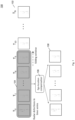
- Fig. 3 shows an illustration 300 of a stacking process according to various embodiments. Radar points from single time step are often not stable, and meaningful information may be inferred only by considering multiple frames. According to various embodiments, multiple frames may be stacked together to encode temporal information. In the stacking process, ego-motion may be considered to compensate the moving of ego-vehicle (in other words: of the vehicle on which the radar sensor is provided). As such, all the points from stationary objects may always be at the same grid position within multiple frames.
- Occupancy grids 208 of various time steps may be stacked to obtain a stacked occupancy grid (which may be represented by a tensor of dimensions T ⁇ H ⁇ W ⁇ C O ). Like indicated by points 308 further maps of various time steps may be stacked. The stacked maps and grids may be provided as input to a (neural) network for further processing.
- the neural network for object detection may take the input of 3D tensor (HxWxC) where C is the number of feature channels. It will be understood that commonly used neural networks may be used.
- a feature encoding layer is provided to convert the inputs (one 5D tensor and three 4-D tensor) into a unified 3D tensor.
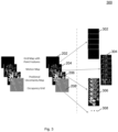
- the feature encoding layer may extract features from points and maps, may squeeze the dimension of points (e.g. by max pooling) and may then concatenate all of them to get a unified 4D tensor (of dimensions TxHxWxF', wherein F' is the sum of the fourth dimension of the representations to be concatenated).
- the stacked positional uncertainty map 306 may be processed by time-distributed convolutions 410 to obtain a positional uncertainty map representation 412 (for example a 4D-tensor, for example of dimensions T ⁇ H ⁇ W ⁇ C U ). Further stacked maps may be processed accordingly (for example by time-distributed CNNs) to get further map representations (for example 4D-tensors).
- a positional uncertainty map representation 412 for example a 4D-tensor, for example of dimensions T ⁇ H ⁇ W ⁇ C U .
- Further stacked maps may be processed accordingly (for example by time-distributed CNNs) to get further map representations (for example 4D-tensors).
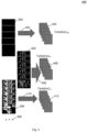
- Fig. 5 shows an illustration 500 of concatenating representations according to various embodiments.
- the point representation 404, the motion map representation 408, and the positional uncertainty map representation 412 may be concatenated, like illustrated by arrows 502, to obtain concatenated data 504. It will be understood that concatenation is possible since the point representation 404, the motion map representation 408, and the positional uncertainty map representation 412 have dimensions which are at least partially identical (for example, the first dimension (corresponding to the number of time steps, for example 5), the second dimension (corresponding to the height of the grid, for example 160), and the third dimension (corresponding to the width of the grid, for example 160) are identical for the point representation 404, the motion map representation 408, and the positional uncertainty map representation 412.
- the first dimension of the concatenated data 504 may be identical to the first dimension of the point representation 404, and identical to the first dimension of the motion map representation 408, and identical to the first dimension of the positional uncertainty map representation 412.
- the second dimension of the concatenated data 504 may be identical to the second dimension of the point representation 404, and identical to the second dimension of the motion map representation 408, and identical to the second dimension of the positional uncertainty map representation 412.
- the third dimension of the concatenated data 504 may be identical to the third dimension of the point representation 404, and identical to the third dimension of the motion map representation 408, and identical to the third dimension of the positional uncertainty map representation 412.
- the fourth dimension of the concatenated data 504 may be identical to the sum of the fourth dimension of the point representation 404 (for example 64 as illustrated in Fig. 5 ), the fourth dimension of the motion map representation 408 (for example 32 as illustrated in Fig. 5 ), and the fourth dimension of the positional uncertainty map representation 412 (for example 32 as illustrated in Fig. 5 ).
- a time fusion layer may be provided to squeeze the time dimension.
- 3D conv or a recurrent network for example LSTM
- the output of this layer may be HxWxF" (with an integer number F"), which may be directly used by an object detection network.
- Fig. 6 shows an illustration 600 of time squeezing according to various embodiments.
- the concatenated data may be provided using time-distributed convolutions (for example using 3D-conv or LSTM) 602, to obtain a pyramid with levels of data of reduced size and upsampled size.
- a first level 604 (for example of dimension T 1 ⁇ H 1 ⁇ W 1 ⁇ C 1 , which may be identical to TxHxWxF') may be processed, for example using convolutions and/ or max pooling to obtain a second level 606 of reduced size (for example T 2 ⁇ H 2 ⁇ W 2 ⁇ C 2 ).
- Level 614 may be obtained based on upsampling level 612 and based on level 608, for example by squeezing the time dimension. Data of level 614 may have dimensions H 3 ⁇ W 3 ⁇ C 3 , i.e. compared to the dimension of level 608, the time dimension T may be squeezed.
- Level 616 may have dimensions H 2 ⁇ W 2 ⁇ C 2 , i.e. compared to the dimension of level 606, the time dimension T may be squeezed.
- Data of level 618 may have dimensions H 1 ⁇ W 1 ⁇ C 1 , i.e. compared to the dimension of level 604, the time dimension T may be squeezed. Any of the levels 616, 618, or the further levels may be obtained based on a lower level that has been obtained based on upsampling and time squeezing (for example a level illustrated in Fig.
- a level that was obtained by downsampling for example a level illustrated in Fig. 6 left from the respective level
- levels 604, 606, 608, 610 may be processed to squeeze time dimension T, to obtain levels 618, 616, 614, 612, respectively.
- Various methods may be used for squeezing the time dimension, for example taking one of the subtensors for a fixed time value (in other words: taking one of the T maps), averaging over all time values (in other words: averaging over all maps along T dimension), taking a maximal or minimal value of all subtensors (in other words: maps) along T dimension, add-up values of all subtensors (in other words: maps) along T dimension, or any other method for removing or reducing the time dimension.
- the output of level 618 may be used for object detection.
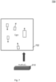
- Fig. 7 shows an illustration 700 of object detection according to various embodiments.
- the output of level 618 may be used for object detection 702, for example using an anchor-based object detection network, for example using Retinanet (or a similar network) on each pyramid level feature map, or any other object detection method.
- object detection 702 for example using an anchor-based object detection network, for example using Retinanet (or a similar network) on each pyramid level feature map, or any other object detection method.
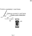
- Fig. 8 shows an illustration 800 of a motion map design for instantaneous probability calculation in a next frame (in other words: at a next (in other words: subsequent) time step) according to various embodiments.
- a vehicle 802 with a radar sensor 802, a radar point detection 804, a radial velocity 806, a distance 808 covered in the next frame, and a positional uncertainty 810 in the next frame are illustrated.
- Fig. 9 shows a flow diagram 900 illustrating a computer implemented method for object detection according to various embodiments.
- a grid may be determined.
- the grid may include a plurality of grid cells.
- a plurality of respective radar detection data for each grid cell may be determined for a plurality of time steps.
- Each radar detection data may indicate a plurality of radar properties.
- a respective radar map indicating a pre-determined radar map property in each grid cell may be determined for each time step.
- the respective radar detection data of the plurality of grid cells for the plurality of time steps may be converted to a point representation of pre-determined first dimensions.
- the radar maps for the plurality of time steps may be converted to a map representation of pre-determined second dimensions.
- the pre-determined first dimensions and the pre-determined second dimensions may be at least partially identical.
- the point representation and the map representation may be concatenated to obtain concatenated data.
- out object detection may be carried based on the concatenated data.
- the computer implemented method may further comprise receiving radar sensor data for each time step from a radar sensor provided on a vehicle; and preprocessing the radar sensor data to remove an effect of a change in location of the vehicle.
- the radar detection data and the radar maps may be determined based on the preprocessed radar sensor data.
- the radar sensor data may be preprocessed to remove the effect of the change in location of the vehicle based on the radar sensor data of the present time step and radar sensor data of a pre-determined number of previous time steps preceding the present time step.
- the respective radar map may comprise a motion map indicating a probability of existence of a radar point detection at a next time step.
- the respective radar map may comprise an occupancy map indicating static object contours.
- converting the respective radar detection data of the plurality of grid cells for the plurality of time steps to the point representation of pre-determined first dimensions may include reducing a dimension of points in each cell.
- reducing the dimension of points may include max pooling.
- the grid may comprise a pre-determined height and a pre-determined width.
- the point representation may comprise a four-dimensional point tensor. A first dimension of the point tensor may correspond to the number of the plurality of time steps, a second dimension of the point tensor may correspond to the height of the grid, and a third dimension of the point tensor may correspond to the width of the grid.
- the map representation may comprise a four-dimensional map tensor. A first dimension of the map tensor may correspond to the number of the plurality of time steps, a second dimension of the map tensor may correspond to the height of the grid, and a third dimension of the map tensor may correspond to the width of the grid.
- the concatenated data may comprise a four-dimensional concatenated tensor.
- a first dimension of the concatenated tensor may correspond to the number of the plurality of time steps
- a second dimension of the concatenated tensor may correspond to the height of the grid
- a third dimension of the concatenated tensor may correspond to the width of the grid
- a fourth dimension of the concatenated tensor may correspond to the sum of a fourth dimension of the point tensor and a fourth dimension of the map tensor.
- reducing the dimension of the concatenated data may comprise using a 3D convolution. According to various embodiments, reducing the dimension of the concatenated data may comprise using a recurrent network.
- steps 902, 904, 906, 908, 910, 912, 914 and the further steps described above may be performed by computer hardware components.
- object detection based on radar point cloud and temporal fusion may be provided.
Landscapes
- Engineering & Computer Science (AREA)
- Remote Sensing (AREA)
- Radar, Positioning & Navigation (AREA)
- Physics & Mathematics (AREA)
- General Physics & Mathematics (AREA)
- Computer Networks & Wireless Communication (AREA)
- Electromagnetism (AREA)
- Theoretical Computer Science (AREA)
- Artificial Intelligence (AREA)
- Evolutionary Computation (AREA)
- Biophysics (AREA)
- Data Mining & Analysis (AREA)
- Computing Systems (AREA)
- General Engineering & Computer Science (AREA)
- General Health & Medical Sciences (AREA)
- Mathematical Physics (AREA)
- Software Systems (AREA)
- Molecular Biology (AREA)
- Computational Linguistics (AREA)
- Biomedical Technology (AREA)
- Life Sciences & Earth Sciences (AREA)
- Health & Medical Sciences (AREA)
- Radar Systems Or Details Thereof (AREA)
- Traffic Control Systems (AREA)
Claims (14)
- Procédé mis en oeuvre par ordinateur pour la détection d'objets, le procédé comprenant les étapes suivantes exécutées par des composants matériels de l'ordinateur et consistant à :- déterminer (902) une grille, la grille comprenant une pluralité de cellules de grille ;- déterminer (904), pour une pluralité de pas de temps, pour chaque cellule de grille, une pluralité de données de détection radar respectives, chaque donnée de détection radar indiquant une pluralité de propriétés radar ;- déterminer (906), pour chaque pas de temps, une carte radar respective indiquant une propriété de carte radar prédéterminée dans chaque cellule de grille ;- convertir (908) les données de détection radar respectives de la pluralité de cellules de grille pour la pluralité de pas de temps en une représentation par points de premières dimensions prédéterminées ;- convertir (910) les cartes radar pour la pluralité de pas de temps en une représentation par carte de deuxièmes dimensions prédéterminées, dans lequel les premières dimensions prédéterminées et les deuxièmes dimensions prédéterminées sont au moins partiellement identiques ;- concaténer (912) la représentation par points et la représentation par carte pour obtenir des données concaténées ; et- effectuer une détection d'objet (914) sur la base des données concaténées ;dans lequel la grille comprend une hauteur prédéterminée et une largeur prédéterminée ;dans lequel la représentation par points comprend un tenseur de points quadridimensionnel,dans lequel une première dimension du tenseur de points correspond au nombre de la pluralité de pas de temps, une deuxième dimension du tenseur de points correspond à la hauteur de la grille et une troisième dimension du tenseur de points correspond à la largeur de la grille ; etdans lequel la représentation par carte comprend un tenseur de carte quadridimensionnel,dans lequel une première dimension du tenseur de carte correspond au nombre de la pluralité de pas de temps, une deuxième dimension du tenseur de carte correspond à la hauteur de la grille et une troisième dimension du tenseur de carte correspond à la largeur de la grille.
- Procédé mis en oeuvre par ordinateur selon la revendication 1, consistant en outre à :recevoir des données de capteur radar pour chaque pas de temps à partir d'un capteur radar prévu sur un véhicule ; etprétraiter les données de capteur radar pour supprimer l'effet d'un changement de localisation du véhicule ;dans lequel les données de détection radar et les cartes radar sont déterminées sur la base des données de capteur radar prétraitées.
- Procédé mis en oeuvre par ordinateur selon la revendication 2,
dans lequel, pour chaque pas de temps actuel, les données de capteur radar sont prétraitées pour supprimer l'effet du changement de localisation du véhicule sur la base des données de capteur radar du pas de temps actuel et des données de capteur radar d'un nombre prédéterminé de pas de temps antérieurs au pas de temps actuel. - Procédé mis en oeuvre par ordinateur selon l'une quelconque des revendications 1 à 3,
dans lequel, pour chaque pas de temps, la carte radar respective comprend une carte de mouvement indiquant la probabilité d'existence d'une détection de point radar au prochain pas de temps. - Procédé mis en oeuvre par ordinateur selon l'une quelconque des revendications 1 à 4,
dans lequel, pour chaque pas de temps, la carte radar respective comprend une carte d'incertitude de position indiquant une incertitude de position au pas de temps respectif. - Procédé mis en oeuvre par ordinateur selon l'une quelconque des revendications 1 à 5,
dans lequel, pour chaque pas de temps, la carte radar respective comprend une carte d'occupation indiquant des contours d'objets statiques. - Procédé mis en oeuvre par ordinateur selon l'une quelconque des revendications 1 à 6,
dans lequel la conversion (908) des données de détection radar respectives de la pluralité de cellules de grille pour la pluralité de pas de temps en une représentation par points de premières dimensions prédéterminées comprend une réduction d'une dimension des points dans chaque cellule. - Procédé mis en oeuvre par ordinateur selon la revendication 7,
dans lequel la réduction de la dimension des points comprend une mise en commun maximale. - Procédé mis en oeuvre par ordinateur selon l'une quelconque des revendications 1 à 8,
dans lequel une quatrième dimension du tenseur quadridimensionnel concaténé correspond à la somme d'une quatrième dimension du tenseur de points et d'une quatrième dimension du tenseur de carte. - Procédé mis en oeuvre par ordinateur selon l'une quelconque des revendications 1 à 9, consistant en outre à :réduire une dimension des données concaténées pour obtenir des données fusionnées dans le temps,dans lequel les données fusionnées dans le temps comprennent un tenseur tridimensionnel fusionné dans le temps, dans lequel une première dimension du tenseur fusionné dans le temps correspond à la hauteur de la grille, une deuxième dimension du tenseur fusionné dans le temps correspond à la largeur de la grille, et une troisième dimension du tenseur fusionné dans le temps correspond à la somme d'une quatrième dimension du tenseur de points et d'une quatrième dimension du tenseur de carte ;dans lequel la détection d'objets est effectuée sur la base des données fusionnées dans le temps.
- Procédé mis en oeuvre par ordinateur selon la revendication 10,
dans lequel la réduction de la dimension des données concaténées comprend l'utilisation d'une convolution 3D. - Procédé mis en oeuvre par ordinateur selon la revendication 10,
dans lequel la réduction de la dimension des données concaténées comprend l'utilisation d'un réseau récurrent. - Système informatique, le système informatique comprenant une pluralité de composants matériels informatiques configurés pour exécuter les étapes du procédé mis en oeuvre par ordinateur selon l'une quelconque des revendications 1 à 12.
- Support non transitoire lisible par ordinateur comprenant des instructions pour l'exécution du procédé mis en oeuvre par ordinateur selon l'une quelconque des revendications 1 à 12.
Priority Applications (3)
| Application Number | Priority Date | Filing Date | Title |
|---|---|---|---|
| EP19187019.5A EP3767332B1 (fr) | 2019-07-18 | 2019-07-18 | Procédés et systèmes de détection radar d'objets |
| US16/904,835 US11604272B2 (en) | 2019-07-18 | 2020-06-18 | Methods and systems for object detection |
| CN202010685414.8A CN112241008B (zh) | 2019-07-18 | 2020-07-16 | 用于对象检测的方法和系统 |
Applications Claiming Priority (1)
| Application Number | Priority Date | Filing Date | Title |
|---|---|---|---|
| EP19187019.5A EP3767332B1 (fr) | 2019-07-18 | 2019-07-18 | Procédés et systèmes de détection radar d'objets |
Publications (2)
| Publication Number | Publication Date |
|---|---|
| EP3767332A1 EP3767332A1 (fr) | 2021-01-20 |
| EP3767332B1 true EP3767332B1 (fr) | 2023-12-13 |
Family
ID=67438000
Family Applications (1)
| Application Number | Title | Priority Date | Filing Date |
|---|---|---|---|
| EP19187019.5A Active EP3767332B1 (fr) | 2019-07-18 | 2019-07-18 | Procédés et systèmes de détection radar d'objets |
Country Status (3)
| Country | Link |
|---|---|
| US (1) | US11604272B2 (fr) |
| EP (1) | EP3767332B1 (fr) |
| CN (1) | CN112241008B (fr) |
Families Citing this family (15)
| Publication number | Priority date | Publication date | Assignee | Title |
|---|---|---|---|---|
| US12187323B2 (en) * | 2019-08-02 | 2025-01-07 | Hitachi Astemo, Ltd. | Aiming device, driving control system, and method for calculating correction amount of sensor data |
| CN116057411A (zh) * | 2020-09-08 | 2023-05-02 | 西梅奥有限公司 | 使用多个车载雷达测量车速 |
| DE102020216196A1 (de) * | 2020-12-17 | 2022-06-23 | Robert Bosch Gesellschaft mit beschränkter Haftung | Verfahren zur Detektion zumindest eines Objektes einer Umgebung mittels Reflexionssignalen eines Radar-Sensorsystems |
| US12307353B2 (en) | 2021-04-14 | 2025-05-20 | Aptiv Technologies AG | Radar system using a machine-learned model for stationary object detection |
| CN113267753B (zh) * | 2021-05-13 | 2022-07-19 | 中国人民解放军军事科学院战争研究院 | 一种基于三维网格的雷达探测仿真方法 |
| KR20220160320A (ko) * | 2021-05-27 | 2022-12-06 | 현대모비스 주식회사 | 차량의 주변 환경 모니터링 장치 및 방법 |
| CN113317791B (zh) * | 2021-05-28 | 2023-03-14 | 温州康宁医院股份有限公司 | 一种基于被测者的音频确定抑郁症严重程度的方法及装置 |
| CN113568068B (zh) * | 2021-07-22 | 2022-03-29 | 河南大学 | 一种基于mpi并行的三维神经网络的强对流天气预测方法 |
| KR20230015658A (ko) | 2021-07-23 | 2023-01-31 | 삼성전자주식회사 | 그리드 맵 생성 장치 및 방법 |
| EP4148456A1 (fr) * | 2021-09-10 | 2023-03-15 | Aptiv Technologies Limited | Procédé mis en oeuvre par ordinateur, système informatique et support lisible par ordinateur pour la détection d'objets dans un véhicule |
| EP4453608A4 (fr) * | 2021-12-21 | 2025-11-19 | Intel Corp | Appareil, système et procédé radar |
| US12360240B2 (en) | 2022-10-07 | 2025-07-15 | Aptiv Technologies AG | Stationary object detection and classification based on low-level radar data |
| US12548248B2 (en) * | 2022-11-16 | 2026-02-10 | Waymo Llc | Late-to-early temporal fusion for point clouds |
| EP4531003A1 (fr) * | 2023-09-26 | 2025-04-02 | Aptiv Technologies AG | Procédés et systèmes de détermination d'informations relatives à un environnement d'un véhicule |
| US20250334672A1 (en) * | 2024-04-25 | 2025-10-30 | GM Global Technology Operations LLC | Radar point cloud aggregation of dynamic objects with minimized disparity |
Family Cites Families (23)
| Publication number | Priority date | Publication date | Assignee | Title |
|---|---|---|---|---|
| US8488877B1 (en) * | 2009-12-02 | 2013-07-16 | Hrl Laboratories, Llc | System for object recognition in colorized point clouds |
| DE102014218092A1 (de) * | 2014-09-10 | 2016-03-10 | Volkswagen Aktiengesellschaft | Erstellen eines Abbilds der Umgebung eines Kraftfahrzeugs und Bestimmen der relativen Geschwindigkeit zwischen dem Kraftfahrzeug und Objekten in der Umgebung |
| US20170168134A1 (en) * | 2015-12-10 | 2017-06-15 | Qualcomm Incorporated | Object Detection |
| US10338208B2 (en) * | 2016-10-27 | 2019-07-02 | GM Global Technology Operations LLC | Object detection in multiple radars |
| EP3340106B1 (fr) * | 2016-12-23 | 2023-02-08 | Hexagon Technology Center GmbH | Procédé et système d'affectation de classes particulières d'intérêt dans des données de mesure |
| US10417498B2 (en) * | 2016-12-30 | 2019-09-17 | Mitsubishi Electric Research Laboratories, Inc. | Method and system for multi-modal fusion model |
| US9691019B1 (en) * | 2017-03-07 | 2017-06-27 | Google Inc. | Depth concatenation using a matrix computation unit |
| KR20190133713A (ko) * | 2017-03-31 | 2019-12-03 | 에이캐럿큐브드 바이 에어버스 엘엘씨 | 운송 수단 센서를 캘리브레이팅하기 위한 시스템 및 방법 |
| CN107609522B (zh) * | 2017-09-19 | 2021-04-13 | 东华大学 | 一种基于激光雷达和机器视觉的信息融合车辆检测系统 |
| DE102017220243B3 (de) * | 2017-11-14 | 2019-02-21 | Continental Automotive Gmbh | Verfahren und vorrichtung zum erkennen einer blockierung einer radarvorrichtung, fahrerassistenzsystem und fahrzeug |
| US11556777B2 (en) * | 2017-11-15 | 2023-01-17 | Uatc, Llc | Continuous convolution and fusion in neural networks |
| US11475351B2 (en) * | 2017-11-15 | 2022-10-18 | Uatc, Llc | Systems and methods for object detection, tracking, and motion prediction |
| US10970553B2 (en) * | 2017-11-15 | 2021-04-06 | Uatc, Llc | Semantic segmentation of three-dimensional data |
| DE102018203591B3 (de) * | 2018-03-09 | 2019-07-04 | Conti Temic Microelectronic Gmbh | Verfahren und System zur Klassifikation von Verkehrsteilnehmern |
| WO2019182974A2 (fr) * | 2018-03-21 | 2019-09-26 | Nvidia Corporation | Estimation de profondeur stéréo à l'aide de réseaux neuronaux profonds |
| US10810792B2 (en) * | 2018-05-31 | 2020-10-20 | Toyota Research Institute, Inc. | Inferring locations of 3D objects in a spatial environment |
| US11966838B2 (en) * | 2018-06-19 | 2024-04-23 | Nvidia Corporation | Behavior-guided path planning in autonomous machine applications |
| KR20200044420A (ko) * | 2018-10-19 | 2020-04-29 | 삼성전자주식회사 | 위치 추정 방법 및 장치 |
| US11422253B2 (en) * | 2018-11-19 | 2022-08-23 | Tdk Corportation | Method and system for positioning using tightly coupled radar, motion sensors and map information |
| US11899099B2 (en) * | 2018-11-30 | 2024-02-13 | Qualcomm Incorporated | Early fusion of camera and radar frames |
| US11520347B2 (en) * | 2019-01-23 | 2022-12-06 | Baidu Usa Llc | Comprehensive and efficient method to incorporate map features for object detection with LiDAR |
| US20200278423A1 (en) * | 2019-03-01 | 2020-09-03 | GM Global Technology Operations LLC | Removing false alarms at the beamforming stage for sensing radars using a deep neural network |
| WO2021016596A1 (fr) * | 2019-07-25 | 2021-01-28 | Nvidia Corporation | Réseau neuronal profond servant à la segmentation de scènes de la route et d'instances d'objets animés pour des applications de conduite autonome |
-
2019
- 2019-07-18 EP EP19187019.5A patent/EP3767332B1/fr active Active
-
2020
- 2020-06-18 US US16/904,835 patent/US11604272B2/en active Active
- 2020-07-16 CN CN202010685414.8A patent/CN112241008B/zh active Active
Also Published As
| Publication number | Publication date |
|---|---|
| EP3767332A1 (fr) | 2021-01-20 |
| US11604272B2 (en) | 2023-03-14 |
| CN112241008A (zh) | 2021-01-19 |
| US20210018615A1 (en) | 2021-01-21 |
| CN112241008B (zh) | 2024-04-16 |
Similar Documents
| Publication | Publication Date | Title |
|---|---|---|
| US11604272B2 (en) | Methods and systems for object detection | |
| CN114708585B (zh) | 一种基于注意力机制的毫米波雷达与视觉融合的三维目标检测方法 | |
| CN108830280B (zh) | 一种基于区域提名的小目标检测方法 | |
| CN113536920A (zh) | 一种半监督三维点云目标检测方法 | |
| US12079970B2 (en) | Methods and systems for semantic scene completion for sparse 3D data | |
| CN115705717A (zh) | 预测载具的邻近区域的多个对象的特性的方法和系统 | |
| CN110796686A (zh) | 目标跟踪方法及设备、存储装置 | |
| EP3293700A1 (fr) | Reconstruction 3d pour véhicule | |
| EP4152274A1 (fr) | Système et procédé permettant de prédire une probabilité d'occupation d'un point dans un environnement, et son procédé de formation | |
| CN116883972B (zh) | 确定障碍物空间位置的方法、模型的训练方法和装置 | |
| CN114926485A (zh) | 图像深度标注方法、装置、设备及存储介质 | |
| CN119625279A (zh) | 多模态的目标检测方法、装置和多模态识别系统 | |
| Meng et al. | Multi‐vehicle multi‐sensor occupancy grid map fusion in vehicular networks | |
| CN113920446B (zh) | 一种基于原始点云处理的3d目标检测方法 | |
| Wei et al. | Spatiotemporal transformer attention network for 3d voxel level joint segmentation and motion prediction in point cloud | |
| CN119919320A (zh) | 基于多模态数据感知的动态点云剔除方法、装置、设备及存储介质 | |
| CN114612353B (zh) | 一种图像处理的方法和装置 | |
| Kim et al. | LiDAR Based 3D object detection using CCD information | |
| RILL | Intuitive Estimation of Speed using Motion and Monocular Depth Information | |
| CN120876838B (zh) | 基于多传感器融合的智能驾驶汽车目标检测系统及方法 | |
| Han et al. | Computer digital technology combined with dynamic visual communication sensors in target tracking with big data | |
| CN118269967B (zh) | 一种车辆防撞控制方法、装置、存储介质及设备 | |
| EP4531003A1 (fr) | Procédés et systèmes de détermination d'informations relatives à un environnement d'un véhicule | |
| CN119540690A (zh) | 点云融合方法及装置、存储介质、终端、计算机程序产品 | |
| CN119229076A (zh) | 用于确定与交通工具环境相关的时空模式的方法 |
Legal Events
| Date | Code | Title | Description |
|---|---|---|---|
| PUAI | Public reference made under article 153(3) epc to a published international application that has entered the european phase |
Free format text: ORIGINAL CODE: 0009012 |
|
| STAA | Information on the status of an ep patent application or granted ep patent |
Free format text: STATUS: THE APPLICATION HAS BEEN PUBLISHED |
|
| AK | Designated contracting states |
Kind code of ref document: A1 Designated state(s): AL AT BE BG CH CY CZ DE DK EE ES FI FR GB GR HR HU IE IS IT LI LT LU LV MC MK MT NL NO PL PT RO RS SE SI SK SM TR |
|
| AX | Request for extension of the european patent |
Extension state: BA ME |
|
| STAA | Information on the status of an ep patent application or granted ep patent |
Free format text: STATUS: REQUEST FOR EXAMINATION WAS MADE |
|
| 17P | Request for examination filed |
Effective date: 20210720 |
|
| RBV | Designated contracting states (corrected) |
Designated state(s): AL AT BE BG CH CY CZ DE DK EE ES FI FR GB GR HR HU IE IS IT LI LT LU LV MC MK MT NL NO PL PT RO RS SE SI SK SM TR |
|
| RAP3 | Party data changed (applicant data changed or rights of an application transferred) |
Owner name: APTIV TECHNOLOGIES LIMITED |
|
| GRAP | Despatch of communication of intention to grant a patent |
Free format text: ORIGINAL CODE: EPIDOSNIGR1 |
|
| STAA | Information on the status of an ep patent application or granted ep patent |
Free format text: STATUS: GRANT OF PATENT IS INTENDED |
|
| RIC1 | Information provided on ipc code assigned before grant |
Ipc: H03M 7/30 20060101ALN20230530BHEP Ipc: G01S 7/41 20060101ALN20230530BHEP Ipc: G01S 13/931 20200101ALI20230530BHEP Ipc: G01S 13/89 20060101ALI20230530BHEP Ipc: G01S 13/72 20060101AFI20230530BHEP |
|
| INTG | Intention to grant announced |
Effective date: 20230622 |
|
| GRAS | Grant fee paid |
Free format text: ORIGINAL CODE: EPIDOSNIGR3 |
|
| GRAA | (expected) grant |
Free format text: ORIGINAL CODE: 0009210 |
|
| STAA | Information on the status of an ep patent application or granted ep patent |
Free format text: STATUS: THE PATENT HAS BEEN GRANTED |
|
| P01 | Opt-out of the competence of the unified patent court (upc) registered |
Effective date: 20231025 |
|
| AK | Designated contracting states |
Kind code of ref document: B1 Designated state(s): AL AT BE BG CH CY CZ DE DK EE ES FI FR GB GR HR HU IE IS IT LI LT LU LV MC MK MT NL NO PL PT RO RS SE SI SK SM TR |
|
| REG | Reference to a national code |
Ref country code: GB Ref legal event code: FG4D |
|
| REG | Reference to a national code |
Ref country code: CH Ref legal event code: EP |
|
| REG | Reference to a national code |
Ref country code: DE Ref legal event code: R096 Ref document number: 602019043123 Country of ref document: DE |
|
| REG | Reference to a national code |
Ref country code: IE Ref legal event code: FG4D |
|
| PG25 | Lapsed in a contracting state [announced via postgrant information from national office to epo] |
Ref country code: GR Free format text: LAPSE BECAUSE OF FAILURE TO SUBMIT A TRANSLATION OF THE DESCRIPTION OR TO PAY THE FEE WITHIN THE PRESCRIBED TIME-LIMIT Effective date: 20240314 |
|
| REG | Reference to a national code |
Ref country code: LT Ref legal event code: MG9D |
|
| PG25 | Lapsed in a contracting state [announced via postgrant information from national office to epo] |
Ref country code: LT Free format text: LAPSE BECAUSE OF FAILURE TO SUBMIT A TRANSLATION OF THE DESCRIPTION OR TO PAY THE FEE WITHIN THE PRESCRIBED TIME-LIMIT Effective date: 20231213 |
|
| REG | Reference to a national code |
Ref country code: NL Ref legal event code: MP Effective date: 20231213 |
|
| PG25 | Lapsed in a contracting state [announced via postgrant information from national office to epo] |
Ref country code: ES Free format text: LAPSE BECAUSE OF FAILURE TO SUBMIT A TRANSLATION OF THE DESCRIPTION OR TO PAY THE FEE WITHIN THE PRESCRIBED TIME-LIMIT Effective date: 20231213 |
|
| PG25 | Lapsed in a contracting state [announced via postgrant information from national office to epo] |
Ref country code: LT Free format text: LAPSE BECAUSE OF FAILURE TO SUBMIT A TRANSLATION OF THE DESCRIPTION OR TO PAY THE FEE WITHIN THE PRESCRIBED TIME-LIMIT Effective date: 20231213 Ref country code: GR Free format text: LAPSE BECAUSE OF FAILURE TO SUBMIT A TRANSLATION OF THE DESCRIPTION OR TO PAY THE FEE WITHIN THE PRESCRIBED TIME-LIMIT Effective date: 20240314 Ref country code: ES Free format text: LAPSE BECAUSE OF FAILURE TO SUBMIT A TRANSLATION OF THE DESCRIPTION OR TO PAY THE FEE WITHIN THE PRESCRIBED TIME-LIMIT Effective date: 20231213 Ref country code: BG Free format text: LAPSE BECAUSE OF FAILURE TO SUBMIT A TRANSLATION OF THE DESCRIPTION OR TO PAY THE FEE WITHIN THE PRESCRIBED TIME-LIMIT Effective date: 20240313 |
|
| REG | Reference to a national code |
Ref country code: AT Ref legal event code: MK05 Ref document number: 1640899 Country of ref document: AT Kind code of ref document: T Effective date: 20231213 |
|
| PG25 | Lapsed in a contracting state [announced via postgrant information from national office to epo] |
Ref country code: NL Free format text: LAPSE BECAUSE OF FAILURE TO SUBMIT A TRANSLATION OF THE DESCRIPTION OR TO PAY THE FEE WITHIN THE PRESCRIBED TIME-LIMIT Effective date: 20231213 |
|
| PG25 | Lapsed in a contracting state [announced via postgrant information from national office to epo] |
Ref country code: SE Free format text: LAPSE BECAUSE OF FAILURE TO SUBMIT A TRANSLATION OF THE DESCRIPTION OR TO PAY THE FEE WITHIN THE PRESCRIBED TIME-LIMIT Effective date: 20231213 Ref country code: RS Free format text: LAPSE BECAUSE OF FAILURE TO SUBMIT A TRANSLATION OF THE DESCRIPTION OR TO PAY THE FEE WITHIN THE PRESCRIBED TIME-LIMIT Effective date: 20231213 Ref country code: NO Free format text: LAPSE BECAUSE OF FAILURE TO SUBMIT A TRANSLATION OF THE DESCRIPTION OR TO PAY THE FEE WITHIN THE PRESCRIBED TIME-LIMIT Effective date: 20240313 Ref country code: NL Free format text: LAPSE BECAUSE OF FAILURE TO SUBMIT A TRANSLATION OF THE DESCRIPTION OR TO PAY THE FEE WITHIN THE PRESCRIBED TIME-LIMIT Effective date: 20231213 Ref country code: LV Free format text: LAPSE BECAUSE OF FAILURE TO SUBMIT A TRANSLATION OF THE DESCRIPTION OR TO PAY THE FEE WITHIN THE PRESCRIBED TIME-LIMIT Effective date: 20231213 Ref country code: HR Free format text: LAPSE BECAUSE OF FAILURE TO SUBMIT A TRANSLATION OF THE DESCRIPTION OR TO PAY THE FEE WITHIN THE PRESCRIBED TIME-LIMIT Effective date: 20231213 |
|
| PG25 | Lapsed in a contracting state [announced via postgrant information from national office to epo] |
Ref country code: IS Free format text: LAPSE BECAUSE OF FAILURE TO SUBMIT A TRANSLATION OF THE DESCRIPTION OR TO PAY THE FEE WITHIN THE PRESCRIBED TIME-LIMIT Effective date: 20240413 |
|
| PG25 | Lapsed in a contracting state [announced via postgrant information from national office to epo] |
Ref country code: CZ Free format text: LAPSE BECAUSE OF FAILURE TO SUBMIT A TRANSLATION OF THE DESCRIPTION OR TO PAY THE FEE WITHIN THE PRESCRIBED TIME-LIMIT Effective date: 20231213 Ref country code: AT Free format text: LAPSE BECAUSE OF FAILURE TO SUBMIT A TRANSLATION OF THE DESCRIPTION OR TO PAY THE FEE WITHIN THE PRESCRIBED TIME-LIMIT Effective date: 20231213 |
|
| PG25 | Lapsed in a contracting state [announced via postgrant information from national office to epo] |
Ref country code: SK Free format text: LAPSE BECAUSE OF FAILURE TO SUBMIT A TRANSLATION OF THE DESCRIPTION OR TO PAY THE FEE WITHIN THE PRESCRIBED TIME-LIMIT Effective date: 20231213 |
|
| PG25 | Lapsed in a contracting state [announced via postgrant information from national office to epo] |
Ref country code: SM Free format text: LAPSE BECAUSE OF FAILURE TO SUBMIT A TRANSLATION OF THE DESCRIPTION OR TO PAY THE FEE WITHIN THE PRESCRIBED TIME-LIMIT Effective date: 20231213 Ref country code: SK Free format text: LAPSE BECAUSE OF FAILURE TO SUBMIT A TRANSLATION OF THE DESCRIPTION OR TO PAY THE FEE WITHIN THE PRESCRIBED TIME-LIMIT Effective date: 20231213 Ref country code: RO Free format text: LAPSE BECAUSE OF FAILURE TO SUBMIT A TRANSLATION OF THE DESCRIPTION OR TO PAY THE FEE WITHIN THE PRESCRIBED TIME-LIMIT Effective date: 20231213 Ref country code: IT Free format text: LAPSE BECAUSE OF FAILURE TO SUBMIT A TRANSLATION OF THE DESCRIPTION OR TO PAY THE FEE WITHIN THE PRESCRIBED TIME-LIMIT Effective date: 20231213 Ref country code: IS Free format text: LAPSE BECAUSE OF FAILURE TO SUBMIT A TRANSLATION OF THE DESCRIPTION OR TO PAY THE FEE WITHIN THE PRESCRIBED TIME-LIMIT Effective date: 20240413 Ref country code: EE Free format text: LAPSE BECAUSE OF FAILURE TO SUBMIT A TRANSLATION OF THE DESCRIPTION OR TO PAY THE FEE WITHIN THE PRESCRIBED TIME-LIMIT Effective date: 20231213 Ref country code: CZ Free format text: LAPSE BECAUSE OF FAILURE TO SUBMIT A TRANSLATION OF THE DESCRIPTION OR TO PAY THE FEE WITHIN THE PRESCRIBED TIME-LIMIT Effective date: 20231213 Ref country code: AT Free format text: LAPSE BECAUSE OF FAILURE TO SUBMIT A TRANSLATION OF THE DESCRIPTION OR TO PAY THE FEE WITHIN THE PRESCRIBED TIME-LIMIT Effective date: 20231213 |
|
| PG25 | Lapsed in a contracting state [announced via postgrant information from national office to epo] |
Ref country code: PT Free format text: LAPSE BECAUSE OF FAILURE TO SUBMIT A TRANSLATION OF THE DESCRIPTION OR TO PAY THE FEE WITHIN THE PRESCRIBED TIME-LIMIT Effective date: 20240415 Ref country code: PL Free format text: LAPSE BECAUSE OF FAILURE TO SUBMIT A TRANSLATION OF THE DESCRIPTION OR TO PAY THE FEE WITHIN THE PRESCRIBED TIME-LIMIT Effective date: 20231213 |
|
| PG25 | Lapsed in a contracting state [announced via postgrant information from national office to epo] |
Ref country code: PT Free format text: LAPSE BECAUSE OF FAILURE TO SUBMIT A TRANSLATION OF THE DESCRIPTION OR TO PAY THE FEE WITHIN THE PRESCRIBED TIME-LIMIT Effective date: 20240415 Ref country code: PL Free format text: LAPSE BECAUSE OF FAILURE TO SUBMIT A TRANSLATION OF THE DESCRIPTION OR TO PAY THE FEE WITHIN THE PRESCRIBED TIME-LIMIT Effective date: 20231213 |
|
| REG | Reference to a national code |
Ref country code: DE Ref legal event code: R097 Ref document number: 602019043123 Country of ref document: DE |
|
| PG25 | Lapsed in a contracting state [announced via postgrant information from national office to epo] |
Ref country code: DK Free format text: LAPSE BECAUSE OF FAILURE TO SUBMIT A TRANSLATION OF THE DESCRIPTION OR TO PAY THE FEE WITHIN THE PRESCRIBED TIME-LIMIT Effective date: 20231213 |
|
| PLBE | No opposition filed within time limit |
Free format text: ORIGINAL CODE: 0009261 |
|
| STAA | Information on the status of an ep patent application or granted ep patent |
Free format text: STATUS: NO OPPOSITION FILED WITHIN TIME LIMIT |
|
| PG25 | Lapsed in a contracting state [announced via postgrant information from national office to epo] |
Ref country code: SI Free format text: LAPSE BECAUSE OF FAILURE TO SUBMIT A TRANSLATION OF THE DESCRIPTION OR TO PAY THE FEE WITHIN THE PRESCRIBED TIME-LIMIT Effective date: 20231213 |
|
| PG25 | Lapsed in a contracting state [announced via postgrant information from national office to epo] |
Ref country code: SI Free format text: LAPSE BECAUSE OF FAILURE TO SUBMIT A TRANSLATION OF THE DESCRIPTION OR TO PAY THE FEE WITHIN THE PRESCRIBED TIME-LIMIT Effective date: 20231213 Ref country code: DK Free format text: LAPSE BECAUSE OF FAILURE TO SUBMIT A TRANSLATION OF THE DESCRIPTION OR TO PAY THE FEE WITHIN THE PRESCRIBED TIME-LIMIT Effective date: 20231213 |
|
| 26N | No opposition filed |
Effective date: 20240916 |
|
| PG25 | Lapsed in a contracting state [announced via postgrant information from national office to epo] |
Ref country code: MC Free format text: LAPSE BECAUSE OF FAILURE TO SUBMIT A TRANSLATION OF THE DESCRIPTION OR TO PAY THE FEE WITHIN THE PRESCRIBED TIME-LIMIT Effective date: 20231213 |
|
| REG | Reference to a national code |
Ref country code: CH Ref legal event code: PL |
|
| PG25 | Lapsed in a contracting state [announced via postgrant information from national office to epo] |
Ref country code: LU Free format text: LAPSE BECAUSE OF NON-PAYMENT OF DUE FEES Effective date: 20240718 |
|
| PG25 | Lapsed in a contracting state [announced via postgrant information from national office to epo] |
Ref country code: LU Free format text: LAPSE BECAUSE OF NON-PAYMENT OF DUE FEES Effective date: 20240718 |
|
| PG25 | Lapsed in a contracting state [announced via postgrant information from national office to epo] |
Ref country code: CH Free format text: LAPSE BECAUSE OF NON-PAYMENT OF DUE FEES Effective date: 20240731 Ref country code: BE Free format text: LAPSE BECAUSE OF NON-PAYMENT OF DUE FEES Effective date: 20240731 |
|
| REG | Reference to a national code |
Ref country code: DE Ref legal event code: R081 Ref document number: 602019043123 Country of ref document: DE Owner name: APTIV TECHNOLOGIES AG, CH Free format text: FORMER OWNER: APTIV TECHNOLOGIES LIMITED, ST. MICHAEL, BB |
|
| REG | Reference to a national code |
Ref country code: BE Ref legal event code: MM Effective date: 20240731 |
|
| PG25 | Lapsed in a contracting state [announced via postgrant information from national office to epo] |
Ref country code: IE Free format text: LAPSE BECAUSE OF NON-PAYMENT OF DUE FEES Effective date: 20240718 |
|
| PG25 | Lapsed in a contracting state [announced via postgrant information from national office to epo] |
Ref country code: FI Free format text: LAPSE BECAUSE OF FAILURE TO SUBMIT A TRANSLATION OF THE DESCRIPTION OR TO PAY THE FEE WITHIN THE PRESCRIBED TIME-LIMIT Effective date: 20231213 |
|
| PGFP | Annual fee paid to national office [announced via postgrant information from national office to epo] |
Ref country code: DE Payment date: 20250618 Year of fee payment: 7 |
|
| PGFP | Annual fee paid to national office [announced via postgrant information from national office to epo] |
Ref country code: GB Payment date: 20250703 Year of fee payment: 7 |
|
| PGFP | Annual fee paid to national office [announced via postgrant information from national office to epo] |
Ref country code: FR Payment date: 20250703 Year of fee payment: 7 |
|
| PG25 | Lapsed in a contracting state [announced via postgrant information from national office to epo] |
Ref country code: CY Free format text: LAPSE BECAUSE OF FAILURE TO SUBMIT A TRANSLATION OF THE DESCRIPTION OR TO PAY THE FEE WITHIN THE PRESCRIBED TIME-LIMIT; INVALID AB INITIO Effective date: 20190718 |
|
| PG25 | Lapsed in a contracting state [announced via postgrant information from national office to epo] |
Ref country code: HU Free format text: LAPSE BECAUSE OF FAILURE TO SUBMIT A TRANSLATION OF THE DESCRIPTION OR TO PAY THE FEE WITHIN THE PRESCRIBED TIME-LIMIT; INVALID AB INITIO Effective date: 20190718 |