EP3767409B1 - Système d'automatisation industrielle (fa), dispositif de commande, et procédé de commande - Google Patents
Système d'automatisation industrielle (fa), dispositif de commande, et procédé de commande Download PDFInfo
- Publication number
- EP3767409B1 EP3767409B1 EP19767391.6A EP19767391A EP3767409B1 EP 3767409 B1 EP3767409 B1 EP 3767409B1 EP 19767391 A EP19767391 A EP 19767391A EP 3767409 B1 EP3767409 B1 EP 3767409B1
- Authority
- EP
- European Patent Office
- Prior art keywords
- controller
- packet data
- controllers
- packet
- stop
- Prior art date
- Legal status (The legal status is an assumption and is not a legal conclusion. Google has not performed a legal analysis and makes no representation as to the accuracy of the status listed.)
- Active
Links
Images







Classifications
-
- G—PHYSICS
- G05—CONTROLLING; REGULATING
- G05B—CONTROL OR REGULATING SYSTEMS IN GENERAL; FUNCTIONAL ELEMENTS OF SUCH SYSTEMS; MONITORING OR TESTING ARRANGEMENTS FOR SUCH SYSTEMS OR ELEMENTS
- G05B19/00—Program-control systems
- G05B19/02—Program-control systems electric
- G05B19/418—Total factory control, i.e. centrally controlling a plurality of machines, e.g. direct or distributed numerical control [DNC], flexible manufacturing systems [FMS], integrated manufacturing systems [IMS] or computer integrated manufacturing [CIM]
- G05B19/4185—Total factory control, i.e. centrally controlling a plurality of machines, e.g. direct or distributed numerical control [DNC], flexible manufacturing systems [FMS], integrated manufacturing systems [IMS] or computer integrated manufacturing [CIM] characterised by the network communication
-
- G—PHYSICS
- G05—CONTROLLING; REGULATING
- G05B—CONTROL OR REGULATING SYSTEMS IN GENERAL; FUNCTIONAL ELEMENTS OF SUCH SYSTEMS; MONITORING OR TESTING ARRANGEMENTS FOR SUCH SYSTEMS OR ELEMENTS
- G05B19/00—Program-control systems
- G05B19/02—Program-control systems electric
- G05B19/04—Program control other than numerical control, i.e. in sequence controllers or logic controllers
- G05B19/05—Programmable logic controllers, e.g. simulating logic interconnections of signals according to ladder diagrams or function charts
-
- G—PHYSICS
- G05—CONTROLLING; REGULATING
- G05B—CONTROL OR REGULATING SYSTEMS IN GENERAL; FUNCTIONAL ELEMENTS OF SUCH SYSTEMS; MONITORING OR TESTING ARRANGEMENTS FOR SUCH SYSTEMS OR ELEMENTS
- G05B2219/00—Program-control systems
- G05B2219/30—Nc systems
- G05B2219/31—From computer integrated manufacturing till monitoring
- G05B2219/31094—Data exchange between modules, cells, devices, processors
-
- G—PHYSICS
- G05—CONTROLLING; REGULATING
- G05B—CONTROL OR REGULATING SYSTEMS IN GENERAL; FUNCTIONAL ELEMENTS OF SUCH SYSTEMS; MONITORING OR TESTING ARRANGEMENTS FOR SUCH SYSTEMS OR ELEMENTS
- G05B2219/00—Program-control systems
- G05B2219/30—Nc systems
- G05B2219/33—Director till display
- G05B2219/33244—Packet information exchange
-
- Y—GENERAL TAGGING OF NEW TECHNOLOGICAL DEVELOPMENTS; GENERAL TAGGING OF CROSS-SECTIONAL TECHNOLOGIES SPANNING OVER SEVERAL SECTIONS OF THE IPC; TECHNICAL SUBJECTS COVERED BY FORMER USPC CROSS-REFERENCE ART COLLECTIONS [XRACs] AND DIGESTS
- Y02—TECHNOLOGIES OR APPLICATIONS FOR MITIGATION OR ADAPTATION AGAINST CLIMATE CHANGE
- Y02P—CLIMATE CHANGE MITIGATION TECHNOLOGIES IN THE PRODUCTION OR PROCESSING OF GOODS
- Y02P90/00—Enabling technologies with a potential contribution to greenhouse gas [GHG] emissions mitigation
- Y02P90/02—Total factory control, e.g. smart factories, flexible manufacturing systems [FMS] or integrated manufacturing systems [IMS]
Definitions
- the present disclosure relates to a technique for stopping a process of buffering packet data for any appropriate controller.
- controllers such as programmable logic controllers (PLCs) and robot controllers have been introduced to various production sites.
- PLCs programmable logic controllers
- robot controllers have been introduced to various production sites.
- the controllers control various types of industrial driving devices to thereby automate manufacturing processes.
- the controller controls the driving device via a field network that performs fixed-cycle communication such as EtherCAT (registered trademark). Packet data is transmitted over this field network, and the controller and the driving device communicate with each other by reading data from and writing data to this packet data.
- EtherCAT registered trademark
- the packet data is saved in a buffer within the controller for abnormality analysis and the like. Since the buffer has a limited capacity, some of the packet data in the buffer is deleted when the buffer is overflown.
- packet data immediately prior to the occurrence of abnormality is important.
- Japanese Patent Laying-Open No. 2011-35664 discloses a controller intended to "enable an abnormality analysis to be easily and reliably performed in the FA system of the EtherCAT.” This controller stops a packet monitoring function upon occurrence of abnormality, to prevent the deletion of important packet data.
- JP 2001 117607 A discloses a controller system.
- each controller in a controller system, constituted of plural controllers mutually connected through a transmission line, each controller is provided with a storing means for storing data to be processed by its own controller and the other controllers and a data writing and reading means for writing the data to be processed by its own controller in the storing means of its own controller and the other controllers, and reading the data written in the storing means from the storing means of its own controller and the other controllers.
- PTL 1 Japanese Patent Laying-Open No. 2011-35664
- a plurality of controllers may be connected to the same network. To conduct a more detailed analysis, not only packet data buffered in one controller but also packet data buffered in another controller may be needed. It is thus desired to prevent the loss of packet data for any appropriate one of controllers connected to the same network.
- the present disclosure has been made to solve the above problem, and an object in one aspect thereof is to provide a technique capable of preventing the loss of packet data for any appropriate one of controllers connected to the same network. This object is achieved by the subject-matters of the independent claims. Further advantageous modifications and embodiments of the invention are the subject-matter of the dependent claims. The invention is defined by the independent claims.
- a plurality of controllers each of which controls a driving device to be controlled.
- the plurality of controllers each include: a buffer; a communication module for performing packet communication with one or more other controllers; a packet monitor module for buffering packet data generated in its own controller and packet data received by its own controller in the buffer; and a stop module for stopping, in response to a predetermined stop condition being satisfied, a buffering function of the packet monitor module for a controller specified from the plurality of controllers.
- each controller can stop not only the buffering function in its own controller, but also the buffering function in another controller.
- the buffering function in another controller can be prevented.
- the stop module stops, in response to receiving a stop instruction to stop a buffering function from the one or more other controllers, a buffering function of the packet monitor module in its own controller.
- the stop module can stop the buffering function not only by transmitting the instruction to stop a buffering function to another controller, but also by receiving the stop instruction from the another controller.
- the packet data has source information for identifying a source controller, and destination information for identifying a destination controller.
- the FA system further includes an external device configured to communicate with the plurality of controllers.
- the external device includes a communication module for receiving packet data stored in the buffer of each of the plurality of controllers from each of the plurality of controllers, and a display for displaying the source information and the destination information about each packet data received from each of the plurality of controllers.
- a record of packet data remains in both a source controller and a destination controller. Therefore, if a pair of records does not remain in controllers, it means that the packet data has been lost for some reason.
- the display of the source information and the destination information for each packet data allows a user to easily determine which packet data has been lost in which controller.
- the display displays packet data having matching source information and matching destination information in a corresponding manner.
- the user can more easily find out which packet data has been lost in which controller.
- the display displays packet data, in which a pair of packet data having matching source information and matching destination information does not exist, in a display mode different from other packet data.
- the user can immediately find out which packet data has been lost.
- the plurality of controllers each include an interface unit for connecting an external storage device, and a save module for saving, in response to a predetermined save condition being satisfied, packet data stored in the buffer of the controller specified from the plurality of controllers in the external storage device connected to the specified controller.
- each controller can save the buffered packet data in the external storage device, to prevent the loss of the buffered packet data.
- a controller that controls a driving device to be controlled includes: a buffer, a communication module for performing packet communication with one or more other controllers; a packet monitor module for buffering packet data generated in the controller and packet data received by the one or more other controllers in the buffer; and a stop module for stopping, in response to a predetermined stop condition being satisfied, a buffering function of the packet monitor module for the controller or a controller specified from the one or more other controllers.
- each controller can stop not only the buffering function in its own controller, but also the buffering function in another controller.
- the buffering function in another controller can be prevented.
- a method of controlling a controller that controls a driving device to be controlled includes: performing packet communication with one or more other controllers; buffering packet data generated in the controller and packet data received by the one or more other controllers in a buffer of the controller; and stopping, in response to a predetermined stop condition being satisfied, the buffering for the controller or a controller specified from the one or more other controllers.
- each controller can stop not only the buffering function in its own controller, but also the buffering function in another controller.
- the buffering function in another controller can be prevented.
- FIG. 1 shows an overview of an FA system 10.
- FA system 10 is a system for controlling an object, such as equipment and an apparatus, to automate a manufacturing process.
- FA system 10 includes a plurality of controllers. Two controllers 100A and 100B are shown in Fig. 1 as an example of the plurality of controllers. The plurality of controllers are hereinafter also collectively referred to as controller(s) 100.
- Controllers 100A and 100B may be connected to a same network N1.
- Network N1 employs EtherNet/IP (registered trademark), for example.
- Controllers 100A and 100B each include a buffer 150, a communication module 152, a packet monitor module 154, and a stop module 156.
- Buffer 150 is a volatile storage area in controller 100, for example.
- buffer 150 is a storage area such as a random access memory (RAM) or a cache memory.
- Communication module 152 is a functional module for implementing communication with another communication device by packet communication.
- the "another communication device” is a concept that includes any appropriate communication device excluding its own controller.
- the another communication device includes another controller, a driving device 300 to be controlled by its own controller (see Fig. 2 ), and an information processing terminal such as a server connected to a controller.
- Packet monitor module 154 is a functional module for capturing transmitted and received packet data. More specifically, packet monitor module 154 sequentially buffers packet data generated in its own controller and packet data received by its own controller from another communication device in buffer 150, for transmission to another communication device. Buffer 150 is limited in size, and packet monitor module 154 manages buffer 150 in a First In First Out (FIFO) mode or a Last In First Out (LIFO) mode.
- FIFO First In First Out
- LIFO Last In First Out
- the "packet data" is a concept that includes any appropriate communication data of a certain size transmitted via controller 100.
- Examples of the packet data include communication data generated in accordance with a communication protocol of EtherNet/IP, communication data generated in accordance with a communication protocol of EtherNet (registered trademark), communication data generated in accordance with a communication protocol of EtherCAT, communication data generated in accordance with a communication protocol of CompoNet (registered trademark), and communication data generated in accordance with a communication protocol of Object Linking and Embedding for Process Control Unified Architecture (OPC-UA).
- EtherNet/IP communication protocol generated in accordance with a communication protocol of EtherNet/IP
- EtherNet registered trademark
- EtherCAT communication protocol generated in accordance with a communication protocol of EtherCAT
- CompoNet registered trademark
- OPC-UA Object Linking and Embedding for Process Control Unified Architecture
- Stop module 156 is a functional module for stopping the function of buffering the packet data by packet monitor module 154. More specifically, in response to a predetermined stop condition 108 being satisfied, stop module 156 stops the buffering function of packet monitor module 154 for a controller specified from controllers connected to network N1. Stop condition 108 is satisfied, for example, in response to the occurrence of an error in its own controller. Stop condition 108 will be described later in detail.
- stop module 156 When its own controller is specified as a stop target, stop module 156 outputs a stop instruction to stop the buffering function to packet monitor module 154 of its own controller. In response to accepting the stop instruction, packet monitor module 154 stops the process of buffering the packet data.
- stop module 156 when another controller is specified as a stop target, stop module 156 generates an instruction to stop the buffering function, and transmits the stop instruction to the another controller via communication module 152. The another controller that has received the stop instruction stops the function of buffering the packet data.
- FA system 10 can stop not only the buffering function in its own controller, but also the buffering function in another controller. Thus, not only the loss of packet data buffered in its own controller, but also the loss of packet data buffered in the another controller can be prevented.
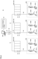
- FIG. 2 schematically shows the apparatus configuration of FA system 10.
- FA system 10 includes one or more controllers 100, one or more development support devices 200, and one or more driving devices 300.
- controllers 100 In the example of Fig. 2 , three controllers 100A to 100C and one development support device 200 are illustrated.
- Controller 100 has a plurality of physical communication ports. A different network may be connected to each communication port. In the example of Fig. 2 , controller 100 has two communication ports P1 and P2. Network N1 is connected to communication port P1. A network N2 is connected to communication port P2.
- Controller 100 and development support device 200 are connected to network N1 via a hub 90. Additionally, any appropriate information processing device may be connected to network N1. In one example, a display such as a human machine interface (HMI) or a server device may be connected to network N1.
- HMI human machine interface
- server device may be connected to network N1.
- development support device 200 examples include a notebook personal computer (PC), a desktop PC, a tablet terminal, and a smartphone.
- a development tool 30 may be installed in development support device 200.
- Development tool 30 is an application for supporting the development of a control program for controller 100.
- Examples of development tool 30 include "Sysmac Studio” manufactured by OMRON Corporation.
- a user can design a control program for controller 100 on development tool 30, and install the designed control program in controller 100.
- the created control program is transmitted to controller 100 as an executable file compiled by development support device 200.
- Lower-level network N2 preferably employs a field network that performs fixed-cycle communication, which guarantees a data arrival time.
- a field network that performs fixed-cycle communication include EtherCAT and CompoNet.
- Controller 100 controls driving device 300 to be controlled in accordance with the control program created on development support device 200.
- Driving device 300 is a collection of devices for directly or indirectly performing prescribed work on a workpiece.
- driving device 300 includes a robot controller 300A, a servo driver 300B, an arm robot 301A controlled by robot controller 300A, a servo motor 301B controlled by servo driver 300B, and the like.
- Driving device 300 may also include a vision sensor for taking an image of the workpiece, and any other device used in the manufacturing process.
- FA system 10 typically has the following setting functions A to C.
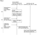
- Fig. 3 is a sequence diagram showing a flow of a setting process for packet monitor module 154 (see Fig. 1 ).
- step S10 development support device 200 accepts operation of starting development tool 30.
- development support device 200 displays a program creation screen.
- Fig. 4 shows a program creation screen 31 which is an example user interface provided by development tool 30.
- Program creation screen 31 is displayed on, for example, a display 221 of development support device 200.
- Fig. 4 shows a user program 210 which is an example control program for controller 100.
- User program 210 may be written in any programming language.
- user program 210 may be defined in a ladder diagram (LD), or is defined in any of an instruction list (IL), a structured text (ST), and a sequential function chart (SFC), or a combination of them.
- user program 210 may be defined in a general-purpose programming language such as JavaScript (registered trademark) or C language.
- user program 210 is written in a ladder diagram.
- a designer can design user program 210 suitable for driving device 300 to be controlled, by combining any appropriate function blocks or defining input-output relations of variables and function blocks on program creation screen 31.
- the function block is a function that is repeatedly used in user program 210 and that has been made into a component.
- user program 210 includes variables "A” to “C” and function blocks FB1, FB2.
- Function block FB1 executes, based on a value of the variable "A” associated with its input unit, a predetermined function defined in function block FB1.
- a result of the execution is reflected in the variable "B” associated with an output unit of function block FB1.
- Function block FB2 executes, based on a value of the variable "B” associated with its input unit, a predetermined function defined in function block FB2.
- a result of the execution is reflected in the variable "C" associated with an output unit of function block FB2.
- the designer can design any appropriate user program 210 by combining the variables and function blocks on program creation screen 31.
- Development tool 30 provides various function blocks.
- above-described stop module 156 (see Fig. 1 ) for stopping the function of buffering the packet data is provided as a function block.
- a start module for starting execution of the function of buffering the packet data is provided as a function block.
- a save module for saving the packet data buffered in buffer 150 in an external storage device (for example, a memory card) is provided as a function block.
- step S12 development tool 30 invokes a setting screen for making various settings for packet monitor module 154 (see Fig. 1 ).
- the setting screen is displayed on display 221 of development support device 200.
- Fig. 5 shows a setting screen 33 which is an example user interface provided by development tool 30.
- Setting screen 33 is a user interface that accepts various settings for packet monitor module 154.
- setting screen 33 includes setting columns 41, 42, 45, 47, a save button 50, and a cancel button 51.
- the settings input to setting screen 33 set a condition for starting the process of buffering the packet data, a condition for stopping the process of buffering the packet data, a condition for saving the packet data, a condition for transferring the packet data, and the like.
- setting column 41 accepts a setting for specifying an operation mode of packet monitor module 154.
- the specifiable operation mode include “start,” “stop,” “save” and “transfer.”
- the specifiable operation modes are listed in response to a button 41A being pressed. The user can select one operation mode from the displayed list of operation modes, to specify the operation mode of packet monitor module 154.
- Setting column 42 accepts a setting for specifying an execution condition.
- an error type of an event log that may occur in controller 100 an error type indicated by packet data, and the like may be specified.
- Candidates for the execution condition that can be specified in setting column 42 are typically defined in advance. For example, the candidates for the specifiable execution condition are listed in response to a button 42A being pressed. The user can select one execution condition from the displayed list of execution condition candidates, to specify the execution condition.
- an execution condition with "start” specified in setting column 41 is also referred to as a "start condition.”
- An execution condition with "stop” specified in setting column 41 is also referred to as a “stop condition.”
- An execution condition with "save” specified in setting column 41 is also referred to as a “save condition.”
- An execution condition with "transfer” specified in setting column 41 is also referred to as a "transfer condition.”
- Setting column 45 accepts a setting for specifying a controller for which the instruction is intended.
- the controller for which the instruction is intended may be selected from among predetermined candidates, or may be specified by input of identification information (for example, a controller name or an IP address) on the controller.
- identification information for example, a controller name or an IP address
- candidates for the controller that can be specified as the controller for which the instruction is intended are listed in response to a button 45A being pressed. The user can select one controller from the displayed list of controller candidates, to specify the controller for which the instruction is intended.
- controller 100 In response to the execution condition specified in setting column 42 being satisfied, controller 100 causes packet monitor module 154 of the controller specified in setting column 45 to operate in the operation mode specified in setting column 41.
- controller 100 when the start condition is satisfied, controller 100 causes the controller for which the instruction is intended and which is associated with the start condition to start executing packet monitor module 154.
- controller 100 When the stop condition is satisfied, controller 100 causes the controller for which the instruction is intended and which is associated with the stop condition to stop packet monitor module 154.
- the stop condition corresponds to above-described stop condition 108 (see Fig. 1 ).
- controller 100 causes the controller for which the instruction is intended and which is associated with the save condition to save the buffered packet data in its own controller.
- controller 100 causes the controller for which the instruction is intended and which is associated with the transfer condition to transfer the buffered packet data to a specified destination.
- Setting column 47 accepts a setting for specifying ON/OFF of a notification function.
- ON is specified in setting column 47, a notification of the occurrence of an error is provided when the execution condition specified in setting column 42 is satisfied.
- the notification of the occurrence of an error may be provided by sound such as an alarm, or by a displayed message and the like.
- OFF is specified in setting column 47, a notification of the occurrence of an error is not provided even when the execution condition specified in setting column 42 is satisfied.
- development support device 200 When save button 50 is pressed, development support device 200 saves setting information 212 that has been input to setting screen 33. When cancel button 51 on setting screen 33 is pressed, development support device 200 closes setting screen 33 without saving setting information 212 that has been input to setting screen 33.
- step S14 development tool 30 accepts compiling operation.
- development tool 30 compiles user program 210 created on program creation screen 31. It is assumed that development tool 30 then accepts operation of downloading a result of the compilation.
- development tool 30 transfers setting information 212 stored in step S12 together with compiled user program 210 to controller 100. Controller 100 saves received user program 210 and setting information 212 in an internal storage device.
- Fig. 6 is a sequence diagram showing a flow of data among controllers 100A to 100C when stop condition 108 is satisfied.
- Fig. 7 is a conceptual diagram schematically showing operation modes of controllers 100A to 100C when stop condition 108 is satisfied.
- Step numbers shown in Fig. 6 correspond to step numbers shown in Fig. 7 .
- step S30A controller 100A is started.
- controller 100A starts executing the packet monitoring function of packet monitor module 154.
- step S30B controller 100B is started.
- controller 100B starts executing the packet monitoring function of packet monitor module 154.
- step S30C controller 100C is started.
- controller 100C starts executing the packet monitoring function of packet monitor module 154.
- step S31A controller 100A accepts an instruction to execute user program 210 stored in its own controller. In response, controller 100A starts executing user program 210.
- controller 100B accepts an instruction to execute user program 210 stored in its own controller. In response, controller 100B starts executing user program 210.
- controller 100C accepts an instruction to execute user program 210 stored in its own controller. In response, controller 100C starts executing user program 210.
- step S32 controller 100A determines whether or not any of the execution conditions defined in setting information 212 has been satisfied. It is assumed, for example, that the stop condition which is an example of the execution conditions has been satisfied. In this case (YES in step S32), controller 100A switches control to step S34. When it is determined that none of the execution conditions defined in setting information 212 has been satisfied (NO in step S32), controller 100A executes the process of step S32 again.
- controllers 100A to 100C have been specified as controllers for which the instruction is intended.
- controller 100A stops the process of buffering the packet data in its own controller, and the process of buffering the packet data in other controllers 100B and 100C.
- stop module 156 of controller 100A stops the buffering function of packet monitor module 154 in its own controller. Accumulation of the packet data in buffer 150 of controller 100A is thus stopped.
- stop module 156 of controller 100A In step S36, stop module 156 of controller 100A generates an instruction to stop the buffering function, and transmits the stop instruction to other controllers 100B and 100C.
- stop module 156 of controller 100B stops the buffering function of packet monitor module 154 of controller 100B. Accumulation of the packet data in buffer 150 of controller 100B is thus stopped.
- stop module 156 of controller 100C stops the buffering function of packet monitor module 154 of controller 100C. Accumulation of the packet data in buffer 150 of controller 100C is thus stopped.
- controller 100 has the function of stopping the buffering functions of its own controller and the other controllers in response to the predetermined stop condition being satisfied.
- the buffering functions of its own controller and the other controllers are simultaneously or substantially simultaneously stopped.
- each controller can leave in buffer 150 packet data buffered in the same period of time.
- Fig. 8 is a sequence diagram showing a flow of a process of collecting the buffered packet data from each controller.
- step S50 development support device 200 accepts operation of displaying an event log screen.
- development support device 200 displays the event log screen.
- Fig. 9 shows an event log screen 35 which is an example user interface provided by development tool 30. Event log screen 35 is displayed on, for example, display 221 of development support device 200.
- Development support device 200 displays event logs collected from each controller 100 on event log screen 35.
- Event log screen 35 has display columns 60 to 65.
- Display column 60 displays the importance of an occurring error.
- Display column 61 displays a communication protocol in which the error has occurred.
- Display column 62 displays a communication port where the error originated.
- Display column 63 displays an event name.
- Display column 64 displays an event code.
- Display column 65 displays a details button.
- step S52 in response to one of the details buttons displayed in display column 65 being pressed, development support device 200 displays a confirmation screen for accepting a determination of whether or not to start the packet collection.
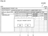
- Fig. 10 shows an example confirmation screen.
- Fig. 10 shows a confirmation screen 70 as an example confirmation screen.
- Confirmation screen 70 has a button 71 indicating "YES” and a button 72 indicating "NO".
- button 71 indicating "YES” is pressed, development support device 200 starts collecting the packet data in each controller 100.
- button 72 indicating "NO” is pressed, development support device 200 simply closes confirmation screen 70.
- step S60 in response to button 71 indicating "YES" on confirmation screen 70 being pressed, development support device 200 transmits a request to acquire packet data to each of specified controllers 100A to 100C.
- controllers 100A to 100C each acquire the packet data stored in buffer 150 (see Fig. 1 ) of its own controller, and transmit the packet data to development support device 200.
- step S70 development support device 200 displays a result of the collection of the packet data collected from each of controllers 100A to 100C.
- Fig. 11 shows a packet data collection result screen 37A which is an example user interface provided by development tool 30.
- Packet data in accordance with EtherCAT, EtherNET, EtherNet/IP and the like includes an EtherNet header.
- This EtherNet header includes source information (for example, an IP address) for identifying a source controller, and destination information (for example, an IP address) for identifying a destination controller. Additionally, the packet data includes information such as a destination port number.
- collection result screen 37A displays the source IP address and the destination IP address for each collected packet data.
- a record of packet data remains in both a source controller and a destination controller. Therefore, if a pair of records does not remain in controllers, it means that the packet data has been lost for some reason.
- the display of the source IP address and the destination IP address for each packet data allows the user to easily determine which packet data has been lost in which controller, thereby facilitating analysis of a communication error.
- collection result screen 37A displays packet data having matching source information and matching destination information in a corresponding manner.
- these packet data pieces are displayed in a row.
- a record of packet data transmitted from controller 100A having an IP address of "A" to controller 100B having an IP address of "B” remains in both controller 100A and controller 100B.
- Development support device 200 displays these corresponding packet data pieces collected from controller 100A and controller 100B side by side. This allows the user to more easily find out which packet data has been lost in which controller, thereby further facilitating the analysis of a communication error.
- collection result screen 37A displays packet data, in which a pair of packet data having matching source information and matching destination information does not exist, in a display mode different from other packet data. That is, packet data in which a pair of packet data does not exist is highlighted.
- the highlighting is implemented by, for example, hatched display, display with a particular color (for example, red), or blinked display. In the example of Fig. 11 , the highlighting is implemented by hatched display (broken line portions 82 and 83). The highlighting of the packet data in which a pair of packet data does not exist allows the user to immediately find out which packet data has been lost.
- Packet data collection result screen 37A is not limited to the example of Fig. 11 .
- Fig. 12 shows a collection result screen 37B, which is a variation of collection result screen 37A.
- collection result screen 37B has a search condition input area 85 and a search result display area 86.
- Search condition input area 85 accepts various conditions for searching for packet data.
- input area 85 accepts identification information on a controller as the search condition.
- the search condition that can be specified in input area 85 is not limited to the identification information on a controller.
- a communication protocol, a port number or the like may be input as the search condition.
- development support device 200 searches the collected packet data for packet data that matches the specified search condition, and lists the packet data that matches the specified search condition in search result display area 86.
- search result for example, an IP address of a source controller, an IP address of a destination controller, a communication protocol that was used for communication, a destination port number, and remarks are displayed.
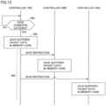
- Fig. 13 is a sequence diagram showing a control flow when the function of saving the packet data is executed.
- step S80 controller 100A determines whether or not the save condition defined in setting information 212 (see Fig. 5 ) has been satisfied. When it is determined that the save condition defined in setting information 212 has been satisfied (YES in step S80), controller 100A switches control to step S82. Otherwise (NO in step S80), controller 100A executes the process of step S80 again.
- Controllers for which the instruction is intended are associated with the save condition defined in setting information 212.
- controllers 100A to 100C are associated, as controllers for which the instruction is intended, with the save condition.
- controller 100A executes a process of saving the packet data buffered in its own controller, and a process of saving the packet data buffered in other controllers 100B and 100C.
- controller 100A saves the packet data buffered in buffer 150 of its own controller in an external storage device (for example, a memory card 140 described later).
- an external storage device for example, a memory card 140 described later.
- controller 100A In step S84, controller 100A generates an instruction to save the packet data, and transmits the save instruction to other controllers 100B and 100C.
- controller 100B In response to receiving the save instruction from controller 100A, controller 100B saves the packet data buffered in buffer 150 of controller 100B in the external storage device (for example, memory card 140 described later). Thus, the packet data in controller 100B is saved in the external storage device.
- controller 100C saves the packet data buffered in buffer 150 of controller 100C in the external storage device (for example, memory card 140 described later). Thus, the packet data in controller 100C is saved in the external storage device.
- Fig. 14 is a sequence diagram showing a control flow when the function of starting the buffering process by packet monitor module 154 is executed.
- step S90 controller 100A determines whether or not the start condition defined in setting information 212 (see Fig. 5 ) has been satisfied. When it is determined that the start condition defined in setting information 212 has been satisfied (YES in step S90), controller 100A switches control to step S92. Otherwise (NO in step S90), controller 100A executes the process of step S90 again.
- Controllers for which the instruction is intended are associated with the start condition defined in setting information 212.
- controllers 100A to 100C are associated, as controllers for which the instruction is intended, with the start condition.
- controller 100A starts a process of buffering the packet data in its own controller, and a process of buffering the packet data in other controllers 100B and 100C.
- controller 100A causes packet monitor module 154 of its own controller to start the buffering function.
- the process of buffering the packet data in buffer 150 of its own controller is started.
- controller 100A In step S94, controller 100A generates an instruction to start the buffering function, and transmits the start instruction to other controllers 100B and 100C.
- controller 100B In response to receiving the start instruction from controller 100A, controller 100B causes packet monitor module 154 of controller 100B to start the buffering function. Accumulation of the packet data in buffer 150 of controller 100B is thus started.
- controller 100C In response to receiving the start instruction from controller 100A, controller 100C causes packet monitor module 154 of controller 100C to start the buffering function. Accumulation of the packet data in buffer 150 of controller 100C is thus started.
- controller 100 has the function of starting the buffering functions of its own controller and the other controllers in response to the predetermined start condition being satisfied.
- the buffering functions of its own controller and the other controllers are simultaneously or substantially simultaneously started.
- Fig. 15 is a schematic diagram showing an example hardware configuration of controller 100.
- Controller 100 includes a communication interface 101, a control device 102 such as a central processing unit (CPU) or a micro-processing unit (MPU), a chip set 104, a main memory 106, a nonvolatile storage device 110, an internal bus controller 122, a fieldbus controller 124, and a memory card interface 139.
- a control device 102 such as a central processing unit (CPU) or a micro-processing unit (MPU)
- a chip set 104 such as a central processing unit (CPU) or a micro-processing unit (MPU)
- main memory 106 such as a central processing unit (CPU) or a micro-processing unit (MPU)
- Control device 102 reads a control program 111 stored in storage device 110, and executes control program 111 by deploying it to main memory 106, thereby implementing any appropriate control on driving device 300 to be controlled and the like.
- Control program 111 includes various programs for controlling controller 100.
- control program 111 includes a system program 109, user program 210, and the like.
- System program 109 includes an instruction code for providing basic functions of controller 100, such as data I/O processing and execution timing control.
- User program 210 is downloaded from development support device 200.
- User program 210 is appropriately designed depending on the control target, and includes a sequence program 210A for performing sequence control and a motion program 210B for performing motion control.
- Chip set 104 controls each component to implement the process as the entire controller 100.
- Storage device 110 stores various types of data in addition to control program 111.
- storage device 110 stores above-described setting information 212 (see Fig. 5 ) and the like.
- Internal bus controller 122 is an interface that exchanges data with various devices coupled to controller 100 through an internal bus. As an example of such devices, an I/O unit 126 is connected.
- Fieldbus controller 124 is an interface that exchanges data with various driving devices 300 coupled to controller 100 through a fieldbus. As an example of such devices, robot controller 300A and servo driver 300B are connected. Additionally, a driving device such as a vision sensor may be connected.
- Internal bus controller 122 and fieldbus controller 124 can provide any appropriate command to the device connected thereto, and also acquire any appropriate data managed by the device. Internal bus controller 122 and/or fieldbus controller 124 also function(s) as an interface for exchanging data with robot controller 300A or servo driver 300B.
- Controller 100 controls data exchange through various wired/wireless networks. Controller 100 communicates with an external device such as development support device 200 via communication interface 101. Controller 100 performs packet communication with another communication device via communication interface 101.
- Memory card interface 139 is an interface unit for connecting memory card 140 (for example, an SD card) which is an example external storage medium.
- Memory card interface 139 is configured such that memory card 140 can be inserted therein and removed therefrom, and can write data to and read data from memory card 140.
- Fig. 16 is a schematic diagram showing the hardware configuration of development support device 200.
- development support device 200 is a computer configured in accordance with a general-purpose computer architecture.
- Development support device 200 includes a control device 202 such as a CPU or an MPU, a main memory 204, a nonvolatile storage device 208, a communication interface 211, an input/output (I/O) interface 214, and a display interface 220. These components are connected to communicate with one another via an internal bus 225.
- Control device 202 executes a development support program 208A stored in storage device 208 by deploying it to main memory 204, thereby implementing various types of control in development tool 30.
- Development support program 208A is a program for providing a development environment of user program 210.
- Storage device 208 stores, in addition to development support program 208A, various types of data and the like generated with development tool 30. Examples of the data include above-described user program 210 created on development tool 30, and above-described setting information 212.
- Communication interface 211 exchanges data with another communication device via a network.
- Examples of the another communication device include controller 100, and an external device such as a server.
- Development support device 200 may be configured to download various programs such as development support program 208A from the another communication device via communication interface 211.
- I/O interface 214 is connected to operation unit 215, and captures a signal indicating user operation from operation unit 215.
- Operation unit 215 is typically a keyboard, a mouse, a touch panel, a touch pad or the like, and accepts operation from the user.
- Display interface 220 is connected to display 221, and transmits an image signal for displaying an image to display 221 in accordance with a command from control device 202 and the like.
- Display 221 is a liquid crystal display (LCD), an organic electro luminescence (EL) display or the like, and presents various types of information to the user.
- LCD liquid crystal display
- EL organic electro luminescence
- display 221 various types of screens provided by development tool 30 (for example, above-described program creation screen 31 and setting screen 33) may be displayed. While development support device 200 and display 221 are shown as separated from each other in the example of Fig. 16 , development support device 200 and display 221 may be integrally configured.
- Fig. 17 shows an example functional configuration of controller 100 and development support device 200.
- controllers 100A and 100B each include, as a functional configuration, a communication instruction execution module 151, communication module 152, a communication driver 153, and packet monitor module 154. These functional modules are implemented in system program 109 (see Fig. 15 ), for example.
- Communication module 152 includes a client function 152A and a server function 152B.
- User program 210 is installed in controllers 100A and 100B on development support device 200.
- User program 210 includes, for example, as one function thereof, stop module 156 for stopping the process of buffering the packet data by packet monitor module 154, a start module 157 for starting the process of buffering the packet data by packet monitor module 154, and a save module 158 for saving the buffered packet data in the external storage device.
- the functional modules of controller 100 are typically executed by control device 102 (see Fig. 15 ).
- Communication instruction execution module 151 is a functional module for controlling communication module 152.
- communication instruction execution module 151 in response to accepting an instruction to stop the buffering from stop module 156, communication instruction execution module 151 generates a CIP parameter for generating a CIP message, and outputs the CIP parameter to client function 152A.
- the CIP parameter will be described later in detail.
- Communication driver 153 is software for communication interface 101 (see Fig. 15 ). Communication driver 153 is provided by a manufacturer depending on the type of communication interface 101, and may be installed in advance or as needed. Controller 100 implements the communication with another controller and development support device 200 via communication driver 153.
- server function 152B stops packet monitor module 154 of its own controller.
- the stop instruction may be voluntarily issued from its own controller, or may be issued from another controller or development support device 200.
- stop instruction is issued from development support device 200.
- the user confirms that an error has occurred in one of controllers 100 on development support device 200, and selects controller 100 in which the buffering function is to be stopped on development support device 200.
- development support device 200 transmits an instruction to stop the buffering function to controller 100A, which is specified controller 100.
- Development support device 200 has a communication module 252 and a communication driver 253 as functional modules.
- Communication module 252 includes a client function 252A.
- the functional modules of development support device 200 are typically executed by control device 202 (see Fig. 16 ).
- Communication driver 253 is software for communication interface 211 (see Fig. 16 ). Communication driver 253 is provided by a manufacturer depending on the type of communication interface 211, and may be installed in advance or as needed. Development support device 200 implements the communication with controller 100 via communication driver 253.
- communication module 152 generates, based on a CIP parameter, a CIP message that defines a control command for packet monitor module 154.
- CIP parameter Specific examples of the CIP parameter will now be described with reference to Figs. 18 to 20 .
- Fig. 18 shows CIP parameters for making settings for packet monitor module 154.
- the CIP parameters include a service code with regard to the setting of enabling/disabling of packet monitor module 154. For example, when “0x4E” is input as the service code, a current set value indicating enabling/disabling of packet monitor module 154 is acquired. When “0x4F” is input as the service code, enabling/disabling of packet monitor module 154 is set in accordance with input.
- the CIP parameters include a service code with regard to various settings for packet monitor module 154. For example, when “0x50" is input as the service code, various current settings for packet monitor module 154 are acquired. When “0x51” is input as the service code, various settings for packet monitor module 154 are set in accordance with input.
- Fig. 19 shows CIP parameters for specifying an instruction to execute packet monitor module 154.
- the CIP parameters include a service code for starting the packet monitoring process of packet monitor module 154 (that is, the process of buffering the packet data). For example, when "0x4B" is input as the service code, the packet monitoring process by packet monitor module 154 is started.
- the CIP parameters include a service code for stopping the packet monitoring process of packet monitor module 154. For example, when "0x4C" is input as the service code, the packet monitoring process by packet monitor module 154 is stopped.
- the CIP parameters include a CIP parameter for saving the packet data buffered by packet monitor module 154 in the external storage device. For example, when "0x4D" is input as the service code, the buffered packet data is saved in the external storage device.
- Fig. 20 shows a CIP parameter for acquiring a current state of packet monitor module 154.
- the CIP parameter includes a service code for acquiring the current state of packet monitor module 154. For example, when "0x52" is input as the service code, the current state of packet monitor module 154 is acquired.
- Examples of the state of packet monitor module 154 include a state in which the packet monitoring is set to disabled, a state indicating that the packet monitoring is being stopped, and a state indicating that the packet monitoring is being executed.
- controller 100 stops the buffering function of packet monitor module 154 for the specified controllers. That is, controller 100 can stop not only the buffering function in its own controller, but also the buffering function in another controller. Thus, not only the loss of packet data buffered in its own controller, but also the loss of packet data buffered in the another controller can be prevented.
Landscapes
- Engineering & Computer Science (AREA)
- Physics & Mathematics (AREA)
- General Physics & Mathematics (AREA)
- Automation & Control Theory (AREA)
- General Engineering & Computer Science (AREA)
- Manufacturing & Machinery (AREA)
- Quality & Reliability (AREA)
- Programmable Controllers (AREA)
Claims (5)
- Système d'automatisation industrielle, FA, comprenant une pluralité de contrôleurs (100A à 100C) dont chacun est configuré pour commander un dispositif d'entraînement à commander, chacun de la pluralité de contrôleurs (100A à 100C) incluant :une mémoire tampon (150) ;un module de communication (152) configuré pour effectuer une communication par paquets avec un ou plusieurs autres contrôleurs ;un module de surveillance de paquets (154) configuré pour mettre en mémoire tampon des données par paquets générées dans son propre contrôleur et des données par paquets reçues par son propre contrôleur dans la mémoire tampon (150) ; etun module d'arrêt (156) configuré pour arrêter, en réponse au fait qu'une condition d'arrêt prédéterminée (108) est satisfaite, une fonction de mise en mémoire tampon du module de surveillance de paquets (154) pour un contrôleur spécifié parmi la pluralité de contrôleurs (100A à 100C), caractérisé en ce queles données par paquets contiennent des informations de source permettant d'identifier un contrôleur de source et des informations de destination permettant d'identifier un contrôleur de destination, etle système FA comprend en outre un dispositif externe (200) configuré pour communiquer avec la pluralité de contrôleurs (100A à 100C), le dispositif externe (200) incluantun module de communication (252) configuré pour recevoir des données par paquets stockées dans la mémoire tampon (150) de chacun de la pluralité de contrôleurs (100A à 100C) à partir de chacun de la pluralité de contrôleurs (100A à 100C), etun afficheur (221) configuré pour afficher les informations de source et les informations de destination concernant chacune des données par paquets reçues de chacun de la pluralité de contrôleurs (100A à 100C),l'afficheur (221) étant configuré pour afficher des données par paquets ayant des informations de source correspondantes et des informations de destination correspondantes de manière correspondante.
- Système FA selon la revendication 1, dans lequel
le module d'arrêt (156) est configuré pour arrêter, en réponse à la réception d'une instruction d'arrêt visant à arrêter une fonction de mise en mémoire tampon provenant d'un ou plusieurs autres contrôleurs, une fonction de mise en mémoire tampon du module de surveillance de paquets (154) dans son propre contrôleur. - Système FA selon la revendication 1, dans lequel
l'afficheur (221) est configuré pour afficher des données par paquets, dans lesquelles une paire de données par paquets ayant des informations de source correspondantes et des informations de destination correspondantes n'existe pas, dans un mode d'affichage différent d'autres données par paquets. - Système FA selon l'une quelconque des revendications 1 à 3, dans lequel
chacun de la pluralité de contrôleurs (100A à 100C) inclutune unité d'interface (139) configurée pour connecter un dispositif de stockage externe (140), etun module de sauvegarde (159) configuré pour sauvegarder, en réponse au fait qu'une condition de sauvegarde prédéterminée est satisfaite, des données par paquets stockées dans la mémoire tampon (150) du contrôleur spécifié parmi la pluralité de contrôleurs (100A à 100C) dans le dispositif de stockage externe (140) connecté au contrôleur spécifié. - Procédé pour un système d'automatisation industrielle, FA, comprenant une pluralité de contrôleurs (100A à 100C) dont chacun est configuré pour commander un dispositif d'entraînement à commander, dans lequel ledit système FA comprend en outre
un dispositif externe (200) configuré pour communiquer avec la pluralité de contrôleurs (100A à 100C),le dispositif externe (200) incluantun module de communication (252) pour recevoir des données par paquets stockées dans une mémoire tampon (150) de chacun de la pluralité de contrôleurs (100A à 100C) provenant de chacun de la pluralité de contrôleurs (100A à 100C), etun afficheur (221) pour afficher les informations de source et les informations de destination concernant chacune des données par paquets reçues de chacun de la pluralité de contrôleurs (100A à 100C),l'affichage (221) étant configuré pour afficher des données par paquets ayant des informations de source correspondantes et des informations de destination correspondantes de manière correspondante, les contrôleurs du système FA étant configurés pour :effectuer une communication par paquets avec un ou plusieurs autres contrôleurs ;mettre en mémoire tampon des données par paquets générées dans le contrôleur et des données par paquets reçues par les un ou plusieurs autres contrôleurs dans une mémoire tampon (150) du contrôleur ; etarrêter, en réponse au fait qu'une condition d'arrêt prédéterminée (108) est satisfaite, la mise en mémoire tampon pour le contrôleur ou un contrôleur spécifié parmi les un ou plusieurs autres contrôleurs, les données par paquets ayant des informations de source pour identifier un contrôleur de source et des informations de destination pour identifier un contrôleur de destination.
Applications Claiming Priority (2)
| Application Number | Priority Date | Filing Date | Title |
|---|---|---|---|
| JP2018043851A JP6984499B2 (ja) | 2018-03-12 | 2018-03-12 | FA(Factory Automation)システム、コントローラ、および制御方法 |
| PCT/JP2019/002736 WO2019176337A1 (fr) | 2018-03-12 | 2019-01-28 | Système d'automatisation industrielle (fa), dispositif de commande, et procédé de commande |
Publications (3)
| Publication Number | Publication Date |
|---|---|
| EP3767409A1 EP3767409A1 (fr) | 2021-01-20 |
| EP3767409A4 EP3767409A4 (fr) | 2021-12-01 |
| EP3767409B1 true EP3767409B1 (fr) | 2025-06-11 |
Family
ID=67908297
Family Applications (1)
| Application Number | Title | Priority Date | Filing Date |
|---|---|---|---|
| EP19767391.6A Active EP3767409B1 (fr) | 2018-03-12 | 2019-01-28 | Système d'automatisation industrielle (fa), dispositif de commande, et procédé de commande |
Country Status (5)
| Country | Link |
|---|---|
| US (1) | US11215974B2 (fr) |
| EP (1) | EP3767409B1 (fr) |
| JP (1) | JP6984499B2 (fr) |
| CN (1) | CN111065976B (fr) |
| WO (1) | WO2019176337A1 (fr) |
Families Citing this family (1)
| Publication number | Priority date | Publication date | Assignee | Title |
|---|---|---|---|---|
| JP7276309B2 (ja) * | 2020-12-25 | 2023-05-18 | 株式会社安川電機 | プログラム作成装置、プログラム作成方法、及びプログラム |
Family Cites Families (26)
| Publication number | Priority date | Publication date | Assignee | Title |
|---|---|---|---|---|
| JP2512201B2 (ja) * | 1990-04-27 | 1996-07-03 | 松下電器産業株式会社 | デ―タの文字列変換表示における通信制御方法及びその回線モニタ及びその通信システム |
| JPH08331146A (ja) * | 1995-06-02 | 1996-12-13 | Hitachi Electron Service Co Ltd | Lanアナライザ |
| US7146408B1 (en) * | 1996-05-30 | 2006-12-05 | Schneider Automation Inc. | Method and system for monitoring a controller and displaying data from the controller in a format provided by the controller |
| JPH11134007A (ja) * | 1997-10-27 | 1999-05-21 | Honda Motor Co Ltd | プログラマブルコントローラを用いた設備の監視システム |
| JP2000047707A (ja) * | 1998-07-27 | 2000-02-18 | Omron Corp | 情報管理装置およびその制御方法 |
| DE19857436A1 (de) * | 1998-12-12 | 2000-06-21 | Kuka Roboter Gmbh | Verfahren zum Behandeln des Spannungsabfalls in der Steuerung eines Roboters und zum Wiederanfahren eines Roboters nach Spannungsabfall |
| JP3810965B2 (ja) * | 1999-10-18 | 2006-08-16 | 株式会社東芝 | コントローラシステム、およびそれを適用したプラント |
| WO2006038663A1 (fr) * | 2004-10-01 | 2006-04-13 | Matsushita Electric Industrial Co., Ltd. | Controleur et pilote de carte memoire et programme informatique |
| JP4247213B2 (ja) * | 2005-07-20 | 2009-04-02 | ファナック株式会社 | 複数のロボット制御装置を備えるロボットシステム及びロボット制御装置 |
| KR20070049926A (ko) * | 2005-11-09 | 2007-05-14 | 삼성전자주식회사 | 멀티미디어신호 수신장치 및 그 제어방법 |
| JP5076488B2 (ja) * | 2006-12-22 | 2012-11-21 | 富士通株式会社 | 情報処理装置、履歴管理方法、履歴管理プログラム |
| JP2008293314A (ja) * | 2007-05-25 | 2008-12-04 | Densei Lambda Kk | 無停電電源装置用のネットワーク通信システム、並びに、無停電電源装置の負荷機器の稼動状態を制御するために通信するコントローラ群を無停電電源装置毎に組分けする方法 |
| JPWO2008146477A1 (ja) * | 2007-05-29 | 2010-08-19 | 光洋電子工業株式会社 | 通信機能を有するplc |
| EP2245868B1 (fr) * | 2007-12-31 | 2012-02-08 | Telefonaktiebolaget L M Ericsson (publ) | Accès internet mobile optimisé |
| EP2316203A4 (fr) * | 2008-08-22 | 2014-12-17 | Ericsson Telefon Ab L M | Procédé et appareil pour éviter des paquets de données non voulus |
| EP2273820A1 (fr) * | 2009-06-30 | 2011-01-12 | Panasonic Corporation | Transfert inter-VPLMN via un noeud de proxy de transfert |
| JP5348489B2 (ja) * | 2009-07-31 | 2013-11-20 | オムロン株式会社 | コントローラ |
| JP5649120B2 (ja) * | 2011-03-03 | 2015-01-07 | 株式会社日立ハイテクインスツルメンツ | 分散型制御システム |
| JP6362821B2 (ja) * | 2012-05-18 | 2018-07-25 | オムロン株式会社 | 制御装置、制御方法および命令セット |
| JP6171386B2 (ja) * | 2013-02-15 | 2017-08-02 | オムロン株式会社 | コントローラ、情報処理装置およびプログラム |
| CN106411820B (zh) * | 2015-07-29 | 2019-05-21 | 中国科学院沈阳自动化研究所 | 一种基于sdn架构的工业通信流传输安全控制方法 |
| KR20170096893A (ko) | 2016-02-17 | 2017-08-25 | 엘에스산전 주식회사 | 통신 패킷 분석 장치 |
| JP6627571B2 (ja) * | 2016-02-26 | 2020-01-08 | オムロン株式会社 | プログラマブルコントローラ、プログラマブルコントローラの制御方法、プログラマブルコントローラの制御プログラム |
| US10764781B2 (en) * | 2016-05-03 | 2020-09-01 | Qualcomm Incorporated | Systems and methods for reordering data received from a plurality of radio access technologies (RATs) |
| US10387392B2 (en) * | 2016-05-17 | 2019-08-20 | Rockwell Automation Technologies, Inc. | Method to automate historian configuration using controller based tag meta attribute |
| WO2018078841A1 (fr) * | 2016-10-31 | 2018-05-03 | 三菱電機株式会社 | Dispositif de coordination de dispositif de capture d'image, programme de coordination de dispositif de capture d'image, système de support de coordination et système de commande |
-
2018
- 2018-03-12 JP JP2018043851A patent/JP6984499B2/ja not_active Expired - Fee Related
-
2019
- 2019-01-28 US US16/643,549 patent/US11215974B2/en active Active
- 2019-01-28 EP EP19767391.6A patent/EP3767409B1/fr active Active
- 2019-01-28 WO PCT/JP2019/002736 patent/WO2019176337A1/fr not_active Ceased
- 2019-01-28 CN CN201980004105.5A patent/CN111065976B/zh active Active
Also Published As
| Publication number | Publication date |
|---|---|
| US20200201297A1 (en) | 2020-06-25 |
| US11215974B2 (en) | 2022-01-04 |
| CN111065976B (zh) | 2024-02-20 |
| EP3767409A4 (fr) | 2021-12-01 |
| WO2019176337A1 (fr) | 2019-09-19 |
| JP6984499B2 (ja) | 2021-12-22 |
| CN111065976A (zh) | 2020-04-24 |
| EP3767409A1 (fr) | 2021-01-20 |
| JP2019159634A (ja) | 2019-09-19 |
Similar Documents
| Publication | Publication Date | Title |
|---|---|---|
| CN107436594B (zh) | 使用基于控制器的元属性的自动化历史记录器配置方法 | |
| US20050228517A1 (en) | Control system setting device | |
| EP3767410B1 (fr) | Système de commande, contrôleur et procédé de commande | |
| EP3506034B1 (fr) | Système de commande | |
| WO2019167512A1 (fr) | Dispositif d'affichage, procédé de génération d'écran, et programme de génération d'écran | |
| US20210064004A1 (en) | Control Device, Control Method, and Control Program | |
| CN111108453B (zh) | 控制系统、控制方法和控制程序 | |
| EP3688532A1 (fr) | Système et procédé pour représenter et utiliser une seule connexion logique avec une collection de modules d'entrée/sortie (e/s) en tant que multiples connexions logiques individuelles | |
| WO2016194099A1 (fr) | Dispositif de débogage, procédé de débogage et programme de débogage | |
| EP3767409B1 (fr) | Système d'automatisation industrielle (fa), dispositif de commande, et procédé de commande | |
| JP4697484B2 (ja) | Plcシステム | |
| JP2019159632A (ja) | 制御システム、開発支援装置、および開発支援プログラム | |
| JP2019159868A (ja) | 制御システム、制御装置および表示装置 | |
| US20210051200A1 (en) | Method for establishing a network communication in an automation system | |
| WO2022190186A1 (fr) | Unité de communication de contrôleur programmable, procédé de stockage de données reçues, et programme | |
| US12461501B2 (en) | Trigger relay unit of programmable controller, trigger transmission system, trigger transmission method, and recording medium | |
| JP2007011936A (ja) | プログラマブル表示器 | |
| JP7691261B2 (ja) | プログラマブルロジックコントローラシステム | |
| US20250173242A1 (en) | Log data analysis assistance system, log data analysis assistance method, recording medium, and assistance device | |
| WO2023228357A1 (fr) | Contrôleur logique programmable, système de commande, procédé de collecte de données et programme | |
| US20250383643A1 (en) | Logging system, logging method, and recording medium | |
| JP2020149520A (ja) | 制御システム、制御方法、および制御プログラム | |
| JP7536217B1 (ja) | プログラマブルコントローラ、端末装置、情報提供方法及びプログラム | |
| JP7412119B2 (ja) | データ活用システム | |
| JP2019159753A (ja) | 制御装置、制御方法、および、制御プログラム |
Legal Events
| Date | Code | Title | Description |
|---|---|---|---|
| STAA | Information on the status of an ep patent application or granted ep patent |
Free format text: STATUS: THE INTERNATIONAL PUBLICATION HAS BEEN MADE |
|
| PUAI | Public reference made under article 153(3) epc to a published international application that has entered the european phase |
Free format text: ORIGINAL CODE: 0009012 |
|
| STAA | Information on the status of an ep patent application or granted ep patent |
Free format text: STATUS: REQUEST FOR EXAMINATION WAS MADE |
|
| 17P | Request for examination filed |
Effective date: 20200330 |
|
| AK | Designated contracting states |
Kind code of ref document: A1 Designated state(s): AL AT BE BG CH CY CZ DE DK EE ES FI FR GB GR HR HU IE IS IT LI LT LU LV MC MK MT NL NO PL PT RO RS SE SI SK SM TR |
|
| AX | Request for extension of the european patent |
Extension state: BA ME |
|
| DAV | Request for validation of the european patent (deleted) | ||
| DAX | Request for extension of the european patent (deleted) | ||
| A4 | Supplementary search report drawn up and despatched |
Effective date: 20211104 |
|
| RIC1 | Information provided on ipc code assigned before grant |
Ipc: G05B 19/418 20060101ALI20211028BHEP Ipc: G05B 19/05 20060101AFI20211028BHEP |
|
| STAA | Information on the status of an ep patent application or granted ep patent |
Free format text: STATUS: EXAMINATION IS IN PROGRESS |
|
| 17Q | First examination report despatched |
Effective date: 20230503 |
|
| GRAP | Despatch of communication of intention to grant a patent |
Free format text: ORIGINAL CODE: EPIDOSNIGR1 |
|
| STAA | Information on the status of an ep patent application or granted ep patent |
Free format text: STATUS: GRANT OF PATENT IS INTENDED |
|
| INTG | Intention to grant announced |
Effective date: 20240814 |
|
| GRAJ | Information related to disapproval of communication of intention to grant by the applicant or resumption of examination proceedings by the epo deleted |
Free format text: ORIGINAL CODE: EPIDOSDIGR1 |
|
| STAA | Information on the status of an ep patent application or granted ep patent |
Free format text: STATUS: EXAMINATION IS IN PROGRESS |
|
| GRAP | Despatch of communication of intention to grant a patent |
Free format text: ORIGINAL CODE: EPIDOSNIGR1 |
|
| STAA | Information on the status of an ep patent application or granted ep patent |
Free format text: STATUS: GRANT OF PATENT IS INTENDED |
|
| INTC | Intention to grant announced (deleted) | ||
| INTG | Intention to grant announced |
Effective date: 20250103 |
|
| GRAS | Grant fee paid |
Free format text: ORIGINAL CODE: EPIDOSNIGR3 |
|
| GRAA | (expected) grant |
Free format text: ORIGINAL CODE: 0009210 |
|
| STAA | Information on the status of an ep patent application or granted ep patent |
Free format text: STATUS: THE PATENT HAS BEEN GRANTED |
|
| AK | Designated contracting states |
Kind code of ref document: B1 Designated state(s): AL AT BE BG CH CY CZ DE DK EE ES FI FR GB GR HR HU IE IS IT LI LT LU LV MC MK MT NL NO PL PT RO RS SE SI SK SM TR |
|
| REG | Reference to a national code |
Ref country code: GB Ref legal event code: FG4D |
|
| REG | Reference to a national code |
Ref country code: CH Ref legal event code: EP |
|
| REG | Reference to a national code |
Ref country code: DE Ref legal event code: R096 Ref document number: 602019071039 Country of ref document: DE |
|
| REG | Reference to a national code |
Ref country code: IE Ref legal event code: FG4D |
|
| PG25 | Lapsed in a contracting state [announced via postgrant information from national office to epo] |
Ref country code: FI Free format text: LAPSE BECAUSE OF FAILURE TO SUBMIT A TRANSLATION OF THE DESCRIPTION OR TO PAY THE FEE WITHIN THE PRESCRIBED TIME-LIMIT Effective date: 20250611 Ref country code: ES Free format text: LAPSE BECAUSE OF FAILURE TO SUBMIT A TRANSLATION OF THE DESCRIPTION OR TO PAY THE FEE WITHIN THE PRESCRIBED TIME-LIMIT Effective date: 20250611 |
|
| REG | Reference to a national code |
Ref country code: LT Ref legal event code: MG9D |
|
| PG25 | Lapsed in a contracting state [announced via postgrant information from national office to epo] |
Ref country code: NO Free format text: LAPSE BECAUSE OF FAILURE TO SUBMIT A TRANSLATION OF THE DESCRIPTION OR TO PAY THE FEE WITHIN THE PRESCRIBED TIME-LIMIT Effective date: 20250911 Ref country code: GR Free format text: LAPSE BECAUSE OF FAILURE TO SUBMIT A TRANSLATION OF THE DESCRIPTION OR TO PAY THE FEE WITHIN THE PRESCRIBED TIME-LIMIT Effective date: 20250912 |
|
| REG | Reference to a national code |
Ref country code: NL Ref legal event code: MP Effective date: 20250611 |
|
| PG25 | Lapsed in a contracting state [announced via postgrant information from national office to epo] |
Ref country code: BG Free format text: LAPSE BECAUSE OF FAILURE TO SUBMIT A TRANSLATION OF THE DESCRIPTION OR TO PAY THE FEE WITHIN THE PRESCRIBED TIME-LIMIT Effective date: 20250611 |
|
| PG25 | Lapsed in a contracting state [announced via postgrant information from national office to epo] |
Ref country code: HR Free format text: LAPSE BECAUSE OF FAILURE TO SUBMIT A TRANSLATION OF THE DESCRIPTION OR TO PAY THE FEE WITHIN THE PRESCRIBED TIME-LIMIT Effective date: 20250611 |
|
| PG25 | Lapsed in a contracting state [announced via postgrant information from national office to epo] |
Ref country code: RS Free format text: LAPSE BECAUSE OF FAILURE TO SUBMIT A TRANSLATION OF THE DESCRIPTION OR TO PAY THE FEE WITHIN THE PRESCRIBED TIME-LIMIT Effective date: 20250911 |
|
| PG25 | Lapsed in a contracting state [announced via postgrant information from national office to epo] |
Ref country code: LV Free format text: LAPSE BECAUSE OF FAILURE TO SUBMIT A TRANSLATION OF THE DESCRIPTION OR TO PAY THE FEE WITHIN THE PRESCRIBED TIME-LIMIT Effective date: 20250611 |
|
| PG25 | Lapsed in a contracting state [announced via postgrant information from national office to epo] |
Ref country code: NL Free format text: LAPSE BECAUSE OF FAILURE TO SUBMIT A TRANSLATION OF THE DESCRIPTION OR TO PAY THE FEE WITHIN THE PRESCRIBED TIME-LIMIT Effective date: 20250611 |
|
| PG25 | Lapsed in a contracting state [announced via postgrant information from national office to epo] |
Ref country code: PT Free format text: LAPSE BECAUSE OF FAILURE TO SUBMIT A TRANSLATION OF THE DESCRIPTION OR TO PAY THE FEE WITHIN THE PRESCRIBED TIME-LIMIT Effective date: 20251013 |
|
| REG | Reference to a national code |
Ref country code: AT Ref legal event code: MK05 Ref document number: 1802750 Country of ref document: AT Kind code of ref document: T Effective date: 20250611 |
|
| PG25 | Lapsed in a contracting state [announced via postgrant information from national office to epo] |
Ref country code: IS Free format text: LAPSE BECAUSE OF FAILURE TO SUBMIT A TRANSLATION OF THE DESCRIPTION OR TO PAY THE FEE WITHIN THE PRESCRIBED TIME-LIMIT Effective date: 20251011 |
|
| PG25 | Lapsed in a contracting state [announced via postgrant information from national office to epo] |
Ref country code: AT Free format text: LAPSE BECAUSE OF FAILURE TO SUBMIT A TRANSLATION OF THE DESCRIPTION OR TO PAY THE FEE WITHIN THE PRESCRIBED TIME-LIMIT Effective date: 20250611 Ref country code: SM Free format text: LAPSE BECAUSE OF FAILURE TO SUBMIT A TRANSLATION OF THE DESCRIPTION OR TO PAY THE FEE WITHIN THE PRESCRIBED TIME-LIMIT Effective date: 20250611 |
|
| PG25 | Lapsed in a contracting state [announced via postgrant information from national office to epo] |
Ref country code: CZ Free format text: LAPSE BECAUSE OF FAILURE TO SUBMIT A TRANSLATION OF THE DESCRIPTION OR TO PAY THE FEE WITHIN THE PRESCRIBED TIME-LIMIT Effective date: 20250611 |
|
| PG25 | Lapsed in a contracting state [announced via postgrant information from national office to epo] |
Ref country code: PL Free format text: LAPSE BECAUSE OF FAILURE TO SUBMIT A TRANSLATION OF THE DESCRIPTION OR TO PAY THE FEE WITHIN THE PRESCRIBED TIME-LIMIT Effective date: 20250611 |
|
| PG25 | Lapsed in a contracting state [announced via postgrant information from national office to epo] |
Ref country code: EE Free format text: LAPSE BECAUSE OF FAILURE TO SUBMIT A TRANSLATION OF THE DESCRIPTION OR TO PAY THE FEE WITHIN THE PRESCRIBED TIME-LIMIT Effective date: 20250611 |
|
| PG25 | Lapsed in a contracting state [announced via postgrant information from national office to epo] |
Ref country code: RO Free format text: LAPSE BECAUSE OF FAILURE TO SUBMIT A TRANSLATION OF THE DESCRIPTION OR TO PAY THE FEE WITHIN THE PRESCRIBED TIME-LIMIT Effective date: 20250611 Ref country code: SK Free format text: LAPSE BECAUSE OF FAILURE TO SUBMIT A TRANSLATION OF THE DESCRIPTION OR TO PAY THE FEE WITHIN THE PRESCRIBED TIME-LIMIT Effective date: 20250611 |
|
| REG | Reference to a national code |
Ref country code: DE Ref legal event code: R097 Ref document number: 602019071039 Country of ref document: DE |
|
| PG25 | Lapsed in a contracting state [announced via postgrant information from national office to epo] |
Ref country code: DK Free format text: LAPSE BECAUSE OF FAILURE TO SUBMIT A TRANSLATION OF THE DESCRIPTION OR TO PAY THE FEE WITHIN THE PRESCRIBED TIME-LIMIT Effective date: 20250611 |
|
| PG25 | Lapsed in a contracting state [announced via postgrant information from national office to epo] |
Ref country code: IT Free format text: LAPSE BECAUSE OF FAILURE TO SUBMIT A TRANSLATION OF THE DESCRIPTION OR TO PAY THE FEE WITHIN THE PRESCRIBED TIME-LIMIT Effective date: 20250611 |
|
| PLBE | No opposition filed within time limit |
Free format text: ORIGINAL CODE: 0009261 |
|
| STAA | Information on the status of an ep patent application or granted ep patent |
Free format text: STATUS: NO OPPOSITION FILED WITHIN TIME LIMIT |
|
| REG | Reference to a national code |
Ref country code: CH Ref legal event code: L10 Free format text: ST27 STATUS EVENT CODE: U-0-0-L10-L00 (AS PROVIDED BY THE NATIONAL OFFICE) Effective date: 20260423 |