EP3767445B1 - Panneau d'affichage et dispositif d'affichage tactile - Google Patents
Panneau d'affichage et dispositif d'affichage tactile Download PDFInfo
- Publication number
- EP3767445B1 EP3767445B1 EP20190422.4A EP20190422A EP3767445B1 EP 3767445 B1 EP3767445 B1 EP 3767445B1 EP 20190422 A EP20190422 A EP 20190422A EP 3767445 B1 EP3767445 B1 EP 3767445B1
- Authority
- EP
- European Patent Office
- Prior art keywords
- touch
- electrodes
- electrode
- sub
- sensing
- Prior art date
- Legal status (The legal status is an assumption and is not a legal conclusion. Google has not performed a legal analysis and makes no representation as to the accuracy of the status listed.)
- Active
Links
Images











Classifications
-
- G—PHYSICS
- G06—COMPUTING OR CALCULATING; COUNTING
- G06F—ELECTRIC DIGITAL DATA PROCESSING
- G06F3/00—Input arrangements for transferring data to be processed into a form capable of being handled by the computer; Output arrangements for transferring data from processing unit to output unit, e.g. interface arrangements
- G06F3/01—Input arrangements or combined input and output arrangements for interaction between user and computer
- G06F3/03—Arrangements for converting the position or the displacement of a member into a coded form
- G06F3/041—Digitisers, e.g. for touch screens or touch pads, characterised by the transducing means
- G06F3/0412—Digitisers structurally integrated in a display
-
- G—PHYSICS
- G06—COMPUTING OR CALCULATING; COUNTING
- G06F—ELECTRIC DIGITAL DATA PROCESSING
- G06F3/00—Input arrangements for transferring data to be processed into a form capable of being handled by the computer; Output arrangements for transferring data from processing unit to output unit, e.g. interface arrangements
- G06F3/01—Input arrangements or combined input and output arrangements for interaction between user and computer
- G06F3/03—Arrangements for converting the position or the displacement of a member into a coded form
- G06F3/041—Digitisers, e.g. for touch screens or touch pads, characterised by the transducing means
-
- G—PHYSICS
- G06—COMPUTING OR CALCULATING; COUNTING
- G06F—ELECTRIC DIGITAL DATA PROCESSING
- G06F3/00—Input arrangements for transferring data to be processed into a form capable of being handled by the computer; Output arrangements for transferring data from processing unit to output unit, e.g. interface arrangements
- G06F3/01—Input arrangements or combined input and output arrangements for interaction between user and computer
- G06F3/03—Arrangements for converting the position or the displacement of a member into a coded form
- G06F3/041—Digitisers, e.g. for touch screens or touch pads, characterised by the transducing means
- G06F3/0416—Control or interface arrangements specially adapted for digitisers
-
- G—PHYSICS
- G06—COMPUTING OR CALCULATING; COUNTING
- G06F—ELECTRIC DIGITAL DATA PROCESSING
- G06F3/00—Input arrangements for transferring data to be processed into a form capable of being handled by the computer; Output arrangements for transferring data from processing unit to output unit, e.g. interface arrangements
- G06F3/01—Input arrangements or combined input and output arrangements for interaction between user and computer
- G06F3/03—Arrangements for converting the position or the displacement of a member into a coded form
- G06F3/041—Digitisers, e.g. for touch screens or touch pads, characterised by the transducing means
- G06F3/0416—Control or interface arrangements specially adapted for digitisers
- G06F3/04164—Connections between sensors and controllers, e.g. routing lines between electrodes and connection pads
-
- G—PHYSICS
- G06—COMPUTING OR CALCULATING; COUNTING
- G06F—ELECTRIC DIGITAL DATA PROCESSING
- G06F3/00—Input arrangements for transferring data to be processed into a form capable of being handled by the computer; Output arrangements for transferring data from processing unit to output unit, e.g. interface arrangements
- G06F3/01—Input arrangements or combined input and output arrangements for interaction between user and computer
- G06F3/03—Arrangements for converting the position or the displacement of a member into a coded form
- G06F3/041—Digitisers, e.g. for touch screens or touch pads, characterised by the transducing means
- G06F3/044—Digitisers, e.g. for touch screens or touch pads, characterised by the transducing means by capacitive means
-
- G—PHYSICS
- G06—COMPUTING OR CALCULATING; COUNTING
- G06F—ELECTRIC DIGITAL DATA PROCESSING
- G06F3/00—Input arrangements for transferring data to be processed into a form capable of being handled by the computer; Output arrangements for transferring data from processing unit to output unit, e.g. interface arrangements
- G06F3/01—Input arrangements or combined input and output arrangements for interaction between user and computer
- G06F3/03—Arrangements for converting the position or the displacement of a member into a coded form
- G06F3/041—Digitisers, e.g. for touch screens or touch pads, characterised by the transducing means
- G06F3/044—Digitisers, e.g. for touch screens or touch pads, characterised by the transducing means by capacitive means
- G06F3/0445—Digitisers, e.g. for touch screens or touch pads, characterised by the transducing means by capacitive means using two or more layers of sensing electrodes, e.g. using two layers of electrodes separated by a dielectric layer
-
- G—PHYSICS
- G06—COMPUTING OR CALCULATING; COUNTING
- G06F—ELECTRIC DIGITAL DATA PROCESSING
- G06F3/00—Input arrangements for transferring data to be processed into a form capable of being handled by the computer; Output arrangements for transferring data from processing unit to output unit, e.g. interface arrangements
- G06F3/01—Input arrangements or combined input and output arrangements for interaction between user and computer
- G06F3/03—Arrangements for converting the position or the displacement of a member into a coded form
- G06F3/041—Digitisers, e.g. for touch screens or touch pads, characterised by the transducing means
- G06F3/044—Digitisers, e.g. for touch screens or touch pads, characterised by the transducing means by capacitive means
- G06F3/0446—Digitisers, e.g. for touch screens or touch pads, characterised by the transducing means by capacitive means using a grid-like structure of electrodes in at least two directions, e.g. using row and column electrodes
-
- H—ELECTRICITY
- H10—SEMICONDUCTOR DEVICES; ELECTRIC SOLID-STATE DEVICES NOT OTHERWISE PROVIDED FOR
- H10K—ORGANIC ELECTRIC SOLID-STATE DEVICES
- H10K50/00—Organic light-emitting devices
- H10K50/80—Constructional details
- H10K50/84—Passivation; Containers; Encapsulations
-
- H—ELECTRICITY
- H10—SEMICONDUCTOR DEVICES; ELECTRIC SOLID-STATE DEVICES NOT OTHERWISE PROVIDED FOR
- H10K—ORGANIC ELECTRIC SOLID-STATE DEVICES
- H10K50/00—Organic light-emitting devices
- H10K50/80—Constructional details
- H10K50/84—Passivation; Containers; Encapsulations
- H10K50/844—Encapsulations
-
- H—ELECTRICITY
- H10—SEMICONDUCTOR DEVICES; ELECTRIC SOLID-STATE DEVICES NOT OTHERWISE PROVIDED FOR
- H10K—ORGANIC ELECTRIC SOLID-STATE DEVICES
- H10K59/00—Integrated devices, or assemblies of multiple devices, comprising at least one organic light-emitting element covered by group H10K50/00
- H10K59/10—OLED displays
- H10K59/12—Active-matrix OLED [AMOLED] displays
-
- H—ELECTRICITY
- H10—SEMICONDUCTOR DEVICES; ELECTRIC SOLID-STATE DEVICES NOT OTHERWISE PROVIDED FOR
- H10K—ORGANIC ELECTRIC SOLID-STATE DEVICES
- H10K59/00—Integrated devices, or assemblies of multiple devices, comprising at least one organic light-emitting element covered by group H10K50/00
- H10K59/10—OLED displays
- H10K59/12—Active-matrix OLED [AMOLED] displays
- H10K59/131—Interconnections, e.g. wiring lines or terminals
-
- H—ELECTRICITY
- H10—SEMICONDUCTOR DEVICES; ELECTRIC SOLID-STATE DEVICES NOT OTHERWISE PROVIDED FOR
- H10K—ORGANIC ELECTRIC SOLID-STATE DEVICES
- H10K59/00—Integrated devices, or assemblies of multiple devices, comprising at least one organic light-emitting element covered by group H10K50/00
- H10K59/40—OLEDs integrated with touch screens
-
- G—PHYSICS
- G06—COMPUTING OR CALCULATING; COUNTING
- G06F—ELECTRIC DIGITAL DATA PROCESSING
- G06F2203/00—Indexing scheme relating to G06F3/00 - G06F3/048
- G06F2203/041—Indexing scheme relating to G06F3/041 - G06F3/045
- G06F2203/04103—Manufacturing, i.e. details related to manufacturing processes specially suited for touch sensitive devices
-
- G—PHYSICS
- G06—COMPUTING OR CALCULATING; COUNTING
- G06F—ELECTRIC DIGITAL DATA PROCESSING
- G06F2203/00—Indexing scheme relating to G06F3/00 - G06F3/048
- G06F2203/041—Indexing scheme relating to G06F3/041 - G06F3/045
- G06F2203/04111—Cross over in capacitive digitiser, i.e. details of structures for connecting electrodes of the sensing pattern where the connections cross each other, e.g. bridge structures comprising an insulating layer, or vias through substrate
-
- G—PHYSICS
- G06—COMPUTING OR CALCULATING; COUNTING
- G06F—ELECTRIC DIGITAL DATA PROCESSING
- G06F2203/00—Indexing scheme relating to G06F3/00 - G06F3/048
- G06F2203/041—Indexing scheme relating to G06F3/041 - G06F3/045
- G06F2203/04112—Electrode mesh in capacitive digitiser: electrode for touch sensing is formed of a mesh of very fine, normally metallic, interconnected lines that are almost invisible to see. This provides a quite large but transparent electrode surface, without need for ITO or similar transparent conductive material
Definitions
- the present disclosure relates to a display panel and a touch display device having a built-in touch panel.
- LCD liquid crystal display
- PDP plasma display panels
- OLED organic light-emitting diode
- Many display devices provide touch-based user interfaces enabling users to intuitively and conveniently input data or instructions directly to devices, rather than using conventional data input systems, such as buttons, a keyboard, or a mouse.
- the ability to sense a touch by a user and to accurately detect coordinates of the touch is required.
- a touch sensing method such as a resistive touch sensing using a resistive film, capacitive touch sensing, electromagnetic induction touch sensing, infrared (IR) touch sensing, or ultrasonic touch sensing, may be used.
- capacitance touch sensing is commonly used to sense a touch and determine touch coordinates, using a plurality of touch electrodes disposed on a touch panel as touch sensors, based on a change in capacitance between touch electrodes or between a touch electrode and a pointer, such as a finger.
- OLED display devices can be fabricated to be relatively light compared to the other display devices, since OLEDs or organic electroluminescent (EL) devices able to emit light themselves are used therein and a separate light source is not required.
- OLEDs or organic electroluminescent (EL) devices able to emit light themselves are used therein and a separate light source is not required.
- OLED display devices are not only advantageous in terms of power consumption, since they are driven at low voltages, but also have desirable qualities, such as the ability to implement a range of colors of light, rapid response rates, wide viewing angles, and high contrast ratios.
- OLED display devices for next-generation displays have been actively researched.
- OLED display devices are significantly advantageous in terms of display, there are significant difficulties and a range of limitations regarding touch panels to be disposed within OLED display devices.
- an encapsulation layer or the like for protecting the OLED display panel from moisture, air, physical impacts, or impurities that would be created during fabrication processing may be provided on the front surface of the OLED display panel to make the OLED display panel reliable.
- the encapsulation layer makes it difficult to determine the positions of touch sensors without lowering display performance.
- high temperature processing for implementing touch sensors including a metal material may damage organic materials in the OLED display panel.
- a touch structure has been realized by attaching a touch panel to an OLED display panel rather than disposing the touch panel within the OLED display panel.
- US 2016/170524 describes a display device including a substrate and a touch electrode layer disposed on the substrate.
- the touch electrode layer includes a touch electrode having a mesh pattern.
- the density of the mesh pattern in a central portion of the touch electrode is different from the density of the mesh pattern at an outer portion of the touch.
- KR 2015 0077831 A1 describes a display device including an active area, a routing area, and a pad area.
- the display device also includes: a plurality of first electrode connection lines which are arranged in the active area, are connected to each of first electrodes arranged in a first direction, and are extended toward the routing area; a plurality of second electrode connection lines which are arranged in the active area, are connected to each of second electrodes arranged in the direction, crossed by the first direction, between the first electrodes, and are extended toward the routing area; a plurality of routing lines which are formed in the routing area and are connected to each extension part of the first connection lines; and a second routing lines which are formed in the routing area and are connected to each extension part of the second connection lines.
- the display device is formed to have a double-layered structure wherein each of the first routing lines is formed on each layer.
- KR 2013 0033232 A1 describes a touch sensor in which a black matrix(112) is formed on an edge unit on a first surface of a substrate(110). A hard insulating film(114) is coated on the first surface of the substrate to cover the black matrix. A touch sensor array is formed on the hard insulating film.
- US 2015/338972 A1 describes a touch panel including a substrate, a conductive sensing layer, an insulation layer and a conductive line layer.
- the substrate includes a central portion and a first peripheral portion.
- the conductive sensing layer is disposed on the central portion.
- the insulation layer includes a second peripheral portion, wherein the second peripheral portion has a trench structure and is disposed on the first peripheral portion.
- the conductive line layer is disposed in the trench structure, and is electrically connected to the conductive sensing layer.
- WO 2016/002279 A1 describes a touch panel including a first electrode side terminal portion that is electrically connected to the upper detection electrode.
- the first electrode side terminal portion includes a first resin layer provided on the first substrate and having the first terminal groove formed therein, and a first conductive material filled in the first terminal groove.
- US 2017/052639 A1 describes a touch panel including a first electrode-side terminal portion that is electrically connected to an upper detection electrode.
- the first electrode-side terminal portion includes a first resin layer which is provided on a first substrate and in which a first terminal groove is formed and a first conductive material which fills the first terminal groove.
- WO 2016/074275 A1 describes a mutual capacitance type OGS touch panel in which a first via hole and a second via hole are formed in an insulation layer of the touch panel. During touch control detection, a first sub-electrode pattern of the touch panel is electrically connected to a fourth sub-electrode pattern through the first via hole, and a third sub-electrode pattern is electrically connected to a second sub-electrode pattern through the second via hole.
- US 2014/160377 A1 decribes a touch panel substrate provided with position detecting electrodes including a black matrix which is made of an electrically conductive material and is electrically connected to a counter electrode.
- US 2016/103517 A1 describes a touch sensor including a first mesh touch electrode formed in a first direction and transmitting a first touch signal, a first supplementary mesh touch electrode formed on the same layer as the first mesh touch electrode, an insulating layer covering the first mesh touch electrode and the first supplementary mesh touch electrode and having a contact cutout, a second mesh touch electrode formed in a second direction crossing the first direction and transmitting a second touch signal, and a second supplementary mesh touch electrode formed on the same layer as the second mesh touch electrode.
- the first mesh touch electrode is connected to the second supplementary mesh touch electrode through the contact cutout and the second mesh touch electrode is connected to the first supplementary mesh touch electrode through the contact cutout.
- the touch panel is fabricated separately from the OLED display panel before being attached to the OLED display panel, thereby causing complex fabrication processing and increased thickness of a resultant OLED display device.
- a touch display device according to claim 1 is provided. Further embodiments are described in the dependent claims.
- FIG. 1 is a schematic view illustrating the configuration of a touch display device 100 according to exemplary embodiments
- FIG. 2A illustrates a display panel 110 according to exemplary embodiments
- FIG. 2B illustrates a built-in touch panel (or a built-in touchscreen panel) TP provided in the display panel 110 according to exemplary embodiments.
- the touch display device 100 further includes, in addition to the display panel 110, a data driving circuit 120, a gate driving circuit 130, and a touch sensing circuit 140.
- the display panel 110 has data lines DL and gate lines GL, as well as subpixels SP defined by the data lines DL and the gate lines GL, to display images.
- the data driving circuit 120 drives the data lines DL of the display panel 110.
- the data driving circuit 120 can supply data voltages to the data lines DL during a display section.
- the gate driving circuit 130 drives the gate lines GL of the display panel 110.
- the gate driving circuit 130 can sequentially supply scanning signals to the gate lines GL during the display section.
- the display panel 110 can also act as the touch panel TP within which touch sensors are disposed to perform touch sensing.
- the display panel 110 may have built-in touch sensors (i.e., touch electrodes) disposed therein.
- touch sensors i.e., touch electrodes
- the touch panel TP may be provided as a built-in component of the display panel 110.
- the touch panel TP is a part of the display panel 110 that is required for touch sensing, and may refer to an assembly of touch sensors provided in the display panel 110.
- the touch sensing circuit 140 senses a touch by a user and/or a touched position using the touch sensors provided in the display panel 110.
- the touch panel TP may have a mutual capacitance-based touch structure or a self-capacitance-based touch structure.
- the touch sensors of the touch panel TP are categorized as driving electrodes (also referred to as transmitting electrodes) and sensing electrodes (also referred to as receiving electrodes), depending on the role and function thereof.
- the touch sensing circuit 140 supplies touch driving signals to the touch sensors corresponding to the driving electrodes and senses a touch and/or touch coordinates, based on touch sensing signals received from the touch sensors corresponding to the sensing electrodes.
- each of the touch sensors of the touch panel TP functions as both a driving electrode (or a transmitting electrode) and a sensing electrode (or a receiving electrode).
- the touch sensing circuit 140 supplies touch driving signals to the touch sensors, receives (or detects) touch sensing signals from the touch sensors to which the touch driving signals have been supplied, and senses a touch and/or touch coordinates, based on the received (or detected) touch sensing signals.
- the touch display device 100 displays images using organic light-emitting diodes (OLEDs) or organic electroluminescent (EL) devices.
- OLEDs organic light-emitting diodes
- EL organic electroluminescent
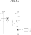
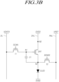
- FIG. 3A and FIG. 3B are schematic circuit diagrams illustrating a subpixel circuit in the display panel 110 according to exemplary embodiments.
- each of the subpixels SP includes, basically, an OLED and a driving transistor DRT driving the OLED.
- each of the subpixels SP further includes a first transistor T1 delivering a data voltage VDATA to a first node N1 of the driving transistor DRT corresponding to a gate node and a storage capacitor C1 maintaining the data voltage VDATA corresponding to an image signal voltage or a voltage corresponding to the data voltage VDATA for the period of a single frame.
- the OLED includes a first electrode (e.g., an anode or a cathode) E1, an organic light-emitting layer EL, and a second electrode (e.g., a cathode or an anode) E2.
- a first electrode e.g., an anode or a cathode
- EL organic light-emitting layer
- a second electrode e.g., a cathode or an anode
- a base voltage EVSS is applied to the second electrode E2 of the OLED.
- the driving transistor DRT can drive the OLED by supplying driving current to the OLED.
- the driving transistor DRT further has a second node N2 and a third node N3, in addition to the first node N1.
- the first node N1 of the driving transistor DRT is a node corresponding to the gate node and is electrically connected to a source node or a drain node of the first transistor T1.
- the second node N2 of the driving transistor DRT is electrically connected to the first electrode E1 of the OLED.
- the second node N2 of the driving transistor DRT may be a source node or a drain node.
- the third node N3 of the driving transistor DRT is a node to which a driving voltage EVDD is applied, and is electrically connected to a driving voltage line DVL through which the driving voltage EVDD is supplied.
- the third node N3 of the driving transistor DRT may be a drain node or a source node.
- the driving transistor DRT and the first transistor T1 may be embodied as n-type transistors or p-type transistors.
- the first transistor T1 is electrically connected between a data line DL and the first node N1 of the driving transistor DRT.
- the first transistor T1 can be controlled by a scanning signal SCAN applied to the gate node of the first transistor T1 through a gate line GL.
- the first transistor T1 can be turned on by the scanning signal SCAN to deliver the data voltage VDATA, supplied through the data line DL, to the first node N1 of the driving transistor DRT.
- the storage capacitor C1 is electrically connected between the first node N1 and the second node N2 of the driving transistor DRT.
- the storage capacitor C1 is not a parasitic capacitor Cgs or Cgd, i.e., an internal capacitor present between the first node N1 and the second node N2 of the driving transistor DRT, but is an external capacitor intentionally designed to be disposed outside of the driving transistor DRT.
- each of the subpixels SP on the display panel 110 further includes a second transistor T2, in addition to the OLED, the driving transistor DRT, the first transistor T1, and the storage capacitor C1.
- the second transistor T2 is electrically connected between the second node N2 of the driving transistor DRT and a reference voltage line RVL through which a reference voltage VREF is supplied.
- the second transistor T2 can be controlled by a sensing signal SENSE, i.e., a scanning signal, supplied to the gate node of the second transistor T2.
- the second transistor T2 is further provided, it is possible to effectively control the voltage status of the second node N2 of the driving transistor DRT in the subpixel SP.
- the second transistor T2 can be turned on by the sensing signal SENSE to apply the reference voltage VREF, supplied through the reference voltage line RVL, to the second node N2 of the driving transistor DRT.
- the subpixel structure illustrated in FIG. 3B is advantageous for accurately initializing the voltage of the second node N2 of the driving transistor DRT and sensing the unique characteristics (e.g., the threshold voltage or the degree of mobility) of the driving transistor DRT and the unique characteristics (e.g., the threshold voltage) of the OLED.
- the scanning signal SCAN and the sensing signal SENSE may be separate gate signals.
- the scanning signal SCAN and the sensing signal SENSE may be applied to the gate node of the first transistor T1 and the gate node of the second transistor T2, respectively, through different gate lines.
- the scanning signal SCAN and the sensing signal SENSE may be identical gate signals.
- the scanning signal SCAN and the sensing signal SENSE may be commonly applied to the gate node of the first transistor T1 and the gate node of the second transistor T2.
- FIG. 4 illustrates the position of a touch sensor TS in the display panel 110 according to exemplary embodiments.
- the touch sensor TS may be directly disposed on an encapsulation layer 400 located on an OLED.
- the encapsulation layer 400 is a layer protecting organic matter contained in an organic light-emitting layer EL from moisture, air, and the like.
- the encapsulation layer 400 is located on the second electrode E2 of the OLED that may act as the cathode.
- the encapsulation layer 400 may be formed of a metal or an inorganic material or may have a multilayer structure in which one or more organic layers and one or more inorganic layers are stacked on each other.
- the touch structure having the touch sensor TS disposed on the encapsulation layer 400 as described above is referred to as a touch-on-encapsulation (TOE) structure.
- TOE touch-on-encapsulation
- a color filter layer may be additionally disposed between the encapsulation layer 400 and the touch sensor TS or may be additionally disposed on the touch sensor TS.
- FIG. 5 illustrates parasitic capacitance Cp formed between the touch sensor TS and the second electrode E2, as well as an influence of the parasitic capacitance Cp on touch sensitivity, in the touch display device according to exemplary embodiments.
- a touch driving signal having a predetermined voltage level may be applied to the touch sensor TS during a touch sensing section.
- Capacitance for touch sensing is capacitance between touch sensors TS or capacitance between a touch sensor TS and a touch object (e.g., a finger or a stylus).
- the capacitance formed between the second electrode E2 and the touch sensor TS is the parasitic capacitance Cp.
- the touch panel TP may be provided as a built-in component in the display panel 110 by directly forming the touch sensor TS on the encapsulation layer 400, thereby significantly reducing the distance D between the second electrode E2 and the touch sensor TS.
- the distance D between the second electrode E2 and the touch sensor TS may be 5 um or greater.
- the encapsulation layer 400 may be formed to have a thickness of 5 um or greater.
- the parasitic capacitance Cp between the second electrode E2 and the touch sensor TS can be reduced. This can consequently reduce RC delay, thereby improving touch sensitivity.
- the thickness of the encapsulation layer 400 may be 5 um or greater but to not exceed a maximum thickness (e.g., 10 um to 20 um, e.g. 20 pm, e.g. 10 pm).
- FIG. 6 illustrates an electrode type touch sensor TS without an open area in the touch display device 100 according to exemplary embodiments.
- each touch sensor TS may be a transparent electrode without an open area.
- the touch sensor TS includes one or more amorphous transparent conductive materials formed by a low temperature deposition process at a process temperature of 100 C° or less.
- the touch sensor TS is designed to have a bulk structure (e.g., a bulk electrode type) without an open area OA as described above, such that the touch sensor TS can be easily patterned.
- a bulk structure e.g., a bulk electrode type
- the touch sensor TS when the touch sensor TS is implemented as a transparent electrode, the touch sensor TS without an influence on light-emitting performance in a subpixel area can be provided as a built-in component within the display panel 110.
- FIG. 7 illustrates an electrode type touch sensor TS having open areas in the touch display device 100 according to exemplary embodiments.
- each touch sensor TS may be a mesh type electrode with one or more open areas OA.
- the area of a single touch sensor TS i.e., a single driving electrode Tx or a single sensing electrode Rx, may be greater than the area of a single subpixel.
- each touch sensor TS may be an opaque electrode or a transparent electrode.
- the touch sensor TS includes one or more amorphous transparent conductive materials formed by a low temperature deposition process at a process temperature of 100 C° or less.
- the open areas OA correspond to the light-emitting areas of the subpixels SP.
- the touch sensor TS can be provided as a built-in component in the display panel 110 without lowering the light-emitting efficiency of each subpixel.
- a TOE structure for mutual capacitance-based touch sensing will be described with reference to FIG. 8 to FIG. 24 .
- a TOE structure for self-capacitance-based touch sensing will be described with reference to FIG. 25 to FIG. 28 .
- FIG. 8 illustrates an exemplary mutual capacitance-based touch panel TP according to an example not forming part of the claimed invention.
- touch sensors TS provided in the mutual capacitance-based touch panel TP include driving lines Tx line and receiving lines Rx line.
- each of the driving lines Tx line and the receiving lines Rx line has a line shape.
- signal lines TL are provided in the display panel 110.
- the signal lines TL are electrically connected to corresponding touch sensors TS.
- the signal lines TL allow the touch sensors TS to be electrically connected to the touch sensing circuit 140.
- Driving signal lines Lt of the signal lines TL are connected to the driving lines Tx line, respectively, while sensing signal lines Lr of the signal lines TL are connected to the receiving lines Rx line, respectively.
- the driving lines Tx line in crossing areas CA, the driving lines Tx line must not be electrically connected to the receiving lines Rx line.
- the driving lines Tx line and the receiving lines Rx line may be present on the same layer or different layers.
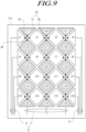
- FIG. 9 illustrates another exemplary mutual capacitance-based touch panel TP according to exemplary embodiments.
- FIG. 9 illustrates an example of the structure in which driving electrodes Tx and sensing electrodes Rx are disposed on the same layer.
- touch sensors TS include driving electrodes Tx and sensing electrodes Rx.
- the driving electrodes Tx located on the same column or the same row are electrically connected via one or more driving bridges (or driving bridge patterns) Bt.
- the electrically connected driving electrodes Tx correspond to a single driving line Tx line in FIG. 8 .
- a driving electrode Tx at a point t1 a driving electrode Tx at a point t2, a driving electrode Tx at a point t3, and a driving electrode Tx at a point t4 are electrically connected by corresponding driving bridges Bt, thereby forming a single driving line Tx line.
- a driving electrode Tx at a point t5, a driving electrode Tx at a point t6, a driving electrode Tx at a point t7, and a driving electrode Tx at a point t8 are electrically connected by corresponding driving bridges Bt, thereby forming a single driving line Tx line.
- a driving electrode Tx at a point t9, a driving electrode Tx at a point t10, a driving electrode Tx at a point t11, and a driving electrode Tx at a point t12 are electrically connected by corresponding driving bridges Bt, thereby forming a single driving line Tx line.
- a driving electrode Tx at a point t13, a driving electrode Tx at a point t14, a driving electrode Tx at a point t15, and a driving electrode Tx at a point t16 are electrically connected by corresponding driving bridges Bt, thereby forming a single driving line Tx line.
- At least one driving electrode among the driving electrodes Tx located on the same column or the same row is electrically connected to one or more driving signal lines Lt.
- the sensing electrodes Rx located on the same column or the same row are electrically connected via one or more sensing bridges (or sensing bridge patterns) Br.
- the electrically connected sensing electrodes Rx correspond to a single receiving line Rx line in FIG. 8 .
- a sensing electrode Rx at a point r1, a sensing electrode Rx at a point r2, a sensing electrode Rx at a point r3, a sensing electrode Rx at a point r4, and a sensing electrode Rx at a point r5 are electrically connected via corresponding sensing bridges Br, thereby forming a single receiving line Rx line.
- a sensing electrode Rx at a point r6, a sensing electrode Rx at a point r7, a sensing electrode Rx at a point r8, a sensing electrode Rx at a point r9, and a sensing electrode Rx at a point r10 are electrically connected via corresponding sensing bridges Br, thereby forming a single receiving line Rx line.
- a sensing electrode Rx at a point r11, a sensing electrode Rx at a point r12, a sensing electrode Rx at a point r13, a sensing electrode Rx at a point r14, and a sensing electrode Rx at a point r15 are electrically connected via corresponding sensing bridges Br, thereby forming a single receiving line Rx line.
- At least one sensing electrode among the sensing electrodes Rx located on the same row or the same column is electrically connected to one or more sensing signal lines Lr corresponding thereto.
- the touch sensing circuit 140 can supply touch driving signals to the driving signal lines Lt and sense a touch and/or a touched position based on touch sensing signals received through the sensing signal lines Lr.
- each of the touch sensors TS of the touch panel TP may be a bulk type touch electrode without an open area OA or a mesh type touch electrode having open areas OA.
- FIG. 10 illustrates further another exemplary mutual capacitance-based touch panel TP according to exemplary embodiments.
- each of touch sensors TS of the touch panel TP is implemented as a mesh type touch electrode having open areas OA.
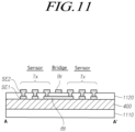
- FIG. 11 is a cross-sectional view taken along line A-A' in the touch panel TP illustrated in FIG. 10
- FIG. 12 is a cross-sectional view taken along line B-B' in the touch panel TP illustrated in FIG. 10 .
- the encapsulation layer 400 is located on a second electrode layer 1110 in which the second electrode E2 acting as the cathode is located.
- Touch sensors TS used for touch sensing may be located directly on the encapsulation layer 400.
- Each of the touch sensors TS is comprised of two or more sub-electrodes SE1 and SE2.
- the two or more sub-electrodes SE1 and SE2 are electrically connected.
- the touch sensors TS are categorized as driving electrodes Tx and sensing electrodes Rx.
- a single driving electrode Tx is comprised of two or more sub-electrodes SE1 and SE2.
- the two or more sub-electrodes SE1 and SE2 of the single driving electrode Tx are located in different layers.
- the two or more sub-electrodes SE1 and SE2 of the single driving electrode Tx are electrically connected via a contact hole extending through an insulation layer 1120.
- a single sensing electrode Rx is comprised of two or more sub-electrodes SE1 and SE2.
- the two or more sub-electrodes SE1 and SE2 of the single sensing electrode Rx are located in different layers.
- the two or more sub-electrodes SE1 and SE2 of the single sensing electrode Rx are electrically connected via a contact hole extending through the insulation layer 1120.
- two driving electrodes Tx are electrically connected, and two sensing electrodes Rx are electrically connected.
- the driving electrode Tx located at a point A and the driving electrode Tx located at a point A' are electrically connected via a driving bridge Bt formed in the same layer and of the same material as the first sub-electrode SE1.
- first sub-electrode SE1 of the driving electrode Tx located at the point A and the first sub-electrode SE1 of the driving electrode Tx located at the point A' are electrically connected via the driving bridge Bt formed of the material of the first sub-electrodes SE1.
- the sensing electrode Rx located at a point B and the sensing electrode Rx located at a point B' are electrically connected via a sensing bridge Br formed in the same layer and of the same material as the second sub-electrode SE2.
- the second sub-electrode SE2 of the sensing electrode Rx located at the point B and the second sub-electrode SE2 of the sensing electrode Rx located at the point B' are electrically connected via the sensing bridge Br formed of the material of the second sub-electrodes SE2.
- the driving bridge Bt and the sensing bridge Br are located in different sub-electrode layers.
- the driving bridge Bt may be located in a first sub-electrode layer in which the first sub-electrode SE1 is disposed, while the sensing bridge Br may be located in a second sub-electrode layer in which the second sub-electrode SE2 is disposed.
- the touch sensors TS have a multi-electrode structure comprised of the first and second sub-electrodes SE1 and SE2, such that the resistance of the touch sensors TS can be significantly reduced. This can consequently improve touch sensitivity by reducing RC delay in the TOE structure having the touch sensors TS disposed on the encapsulation layer 400 in which RC delay would otherwise be inevitably increased.
- pads (not shown) connecting the signal lines TL to the touch sensing circuit 140 may be formed of the same material as one of the two or more sub-electrodes SE1 and SE2.
- FIG. 13 and FIG. 14 illustrate open areas of a touch sensor TS and light-emitting areas in the touch display device 100 according to an embodiment ( FIG.13 ) and a mere example ( FIG. 14 ) not forming part of the claimed invention.
- a single touch sensor TS is formed in an area TSA of a plurality of subpixels, except for the light-emitting areas of the subpixels.
- a single touch sensor TS includes a plurality of open areas OA, each of which corresponds to a light-emitting area of a single subpixel defined by banks 1400.
- FIG. 15 illustrates a multi-electrode structure of touch sensors TS and a single line structure of signal lines TL in the touch display device 100 according to an example not forming part of the claimed invention
- FIG. 16 illustrates a multi-electrode structure of touch sensors TS and a multi-line structure of signal lines TL in the touch display device 100 according to an example not forming part of the claimed invention
- signal lines TL electrically connecting the plurality of touch sensors TS to the touch sensing circuit 140 are also disposed on the encapsulation layer 400.
- the signal lines TL may have a single-line structure as illustrated in FIG. 15 or may have a multi-line structure as illustrated in FIG. 16 .
- each of the signal lines TL is comprised of two or more sub-lines SL1 and SL2, as illustrated in FIG. 16 .
- each of the signal lines TL is comprised of two or more sub-lines SL1 and SL2 as described above, the resistance of the signal line TL can be reduced. This can consequently reduce RC delay and improve signal transmission performance.
- each of the driving electrodes Tx and the sensing electrodes Rx corresponding to the touch sensors TS is comprised of two sub-electrodes SE1 and SE2 and each of the driving signal lines Lt and sensing signal lines Lr of the signal lines TL is comprised of two sub-lines SL1 and SL2.
- the second sub-electrodes SE2 are electrically connected to the first sub-electrodes SE1 via contact holes formed in the insulation layer 1120.
- FIG. 17 and FIG. 18 illustrate an exemplary structure for improving the sensitivity of the touch sensors TS in the touch display device 100 according to exemplary embodiments.
- transparent electrodes 1700 are disposed below the touch sensors TS.
- each of the transparent electrodes 1700 is disposed between the encapsulation layer 400 and the first sub-electrode SE1 of the touch sensor TS corresponding thereto.
- the transparent electrodes 1700 may be disposed on the touch sensors TS. Specifically, each of the transparent electrodes 1700 may be disposed on the uppermost sub-electrode (SE2 in FIG. 17 ) among the two or more sub-electrodes of the touch sensor TS corresponding thereto.
- each of the transparent electrodes 1700 may be disposed between the two or more sub-electrodes of the touch sensor TS corresponding thereto.
- Each touch sensor TS may be comprised of two or more sub-electrodes SE1 and SE2 and a transparent electrode 1700 as described above.
- the touch sensor TS when the touch sensor TS (SE1, SE2) is formed as a transparent electrode, the touch sensor TS can transmit light coming from below (e.g., the second electrode layer 1110). Therefore, even if the size (area) of the touch sensor TS is increased in order to increase the touch sensitivity, the touch sensor TS does not lower the light emitting performance for image display.
- the touch sensor TS is formed as a transparent electrode, the image display performance is not deteriorated by the touch sensor TS. As a result, the area of the touch sensor TS can be increased, and the touch sensitivity of the touch sensor TS can be increased.
- the area (e.g., footprint) of the transparent electrode 1700 is greater than the area (e.g., footprint) of either the first sub-electrode SE1 or the second sub-electrode SE2.
- the width W2 of the transparent electrode 1700 is greater than the width W1 of either the first sub-electrode SE1 or the second sub-electrode SE2.
- the above-described structure of the transparent electrodes 1700 can increase the substantial area of the touch sensors TS without reducing the light-emitting areas. This can consequently increase capacitance associated with touch sensing, thereby improving touch sensitivity.
- the above-described structure of the transparent electrodes 1700 is applicable to both the mutual capacitance-based touch structure and the self-capacitance-based touch structure.
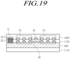
- FIG. 19 illustrates an exemplary structure for protecting the touch sensors TS in the touch display device 100 according to an example not forming part of the claimed invention.
- a passivation layer 1900 is disposed on the touch sensors TS.
- the passivation layer 1900 is able to protect the underlying touch sensors TS.
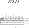
- FIG. 20 illustrates an exemplary interlayer protection structure in the touch display device 100 according to an example not forming part of the claimed invention.
- a buffer layer 2000 is disposed between the encapsulation layer 400 and the touch sensors TS.
- the buffer layer 2000 may be formed of an organic material or an inorganic material.
- the buffer layer 2000 can prevent the encapsulation layer 400 from being damaged by the touch sensors TS formed of metal during or after the fabrication of the panel.
- FIG. 21 illustrates an example of modified bridges in the touch display device 100 according to an example not forming part of the claimed invention.
- two touch sensors are electrically connected via a single bridge Br as illustrated in FIG. 11
- two or more bridges Br may be provided as illustrated in FIG. 21 .
- This configuration can reduce the resistance of the bridges Br, thereby improving signal transmission performance.
- FIG. 22 illustrates another exemplary mutual capacitance-based touch panel TP in which electrode type touch sensors TS without an open area are disposed, according to an example not forming part of the claimed invention
- FIG. 23 is a cross-sectional view taken along line A-A' in the touch panel TP illustrated in FIG. 22
- FIG. 24 is a cross-sectional view taken along line B-B' in the touch panel TP illustrated in FIG. 22 .
- the cross-section illustrated in FIG. 23 is substantially the same as the cross-section illustrated in FIG. 11 , except that the driving electrodes Tx do not have open areas OA.
- the first sub-electrode SE1 and the second sub-electrode SE2 may be in contact with each other at several points or over the entirety of the surface thereof.
- the cross-section illustrated in FIG. 24 is substantially the same as the cross-section illustrated in FIG. 12 , except that the sensing electrodes Rx do not have open areas OA.
- the first sub-electrode SE1 and the second sub-electrode SE2 may be in contact with each other at several points or the entirety of the surface thereof.
- FIG. 25 illustrates an exemplary self-capacitance-based touch panel TP in which electrode type touch sensors TS having open areas are disposed, according to an example not forming part of the claimed invention
- the built-in touch sensors TS of the display panel 110 are electrically isolated from each other.
- signal lines TL are electrically connected to the touch sensors TS and are electrically isolated from each other.
- the touch sensing circuit 140 can supply touch driving signals to the signal lines TL and can sense a touch or a touched position based on touch sensing signals received from the signal lines TL.
- the application of the self-capacitance-based touch structure as described above can advantageously facilitate the arrangement of the touch sensors in a single layer, thereby reducing the thickness of the display panel 110 provided with the built-in touch panel. Consequently, self-capacitance-based touch sensing can be driven and performed more simply while being more resistant to noise, compared to mutual capacitance-based touch sensing.
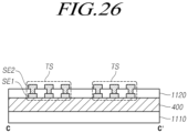
- FIG. 26 is a cross-sectional view taken along line C-C' in the touch panel TP illustrated in FIG. 25 .
- the encapsulation layer 400 is located on a second electrode layer 1110 in which the second electrode E2 acting as the cathode is located.
- the touch sensors TS for self-capacitance-based touch sensing are located on the encapsulation layer 400.
- Each of the touch sensors TS is comprised of two or more sub-electrodes SE1 and SE2.
- the two or more sub-electrodes SE1 and SE2 of the single touch sensor TS are electrically connected to each other.
- the two or more sub-electrodes SE1 and SE2 of the single touch sensor TS are electrically connected to each other via a contact hole extending through an insulation layer 1120.
- FIG. 27 illustrates an exemplary self-capacitance-based touch panel TP in which electrode type touch sensors TS without an open area are disposed, according to an example not forming part of the claimed invention
- FIG. 28 is a cross-sectional view taken along line C-C' in the touch panel TP illustrated in FIG. 27 .
- the encapsulation layer 400 is located on a second electrode layer 1110 in which the second electrode E2 acting as the cathode is located.
- the touch sensors TS for self-capacitance-based touch sensing are located on the encapsulation layer 400.
- Each of the touch sensors TS is comprised of two or more sub-electrodes SE1 and SE2.
- the two or more sub-electrodes SE1 and SE2 of the single touch sensor TS are electrically connected to each other.
- the two or more sub-electrodes SE1 and SE2 of the single touch sensor TS are electrically connected to each other via a contact hole extending through an insulation layer 1120.
- the bulk type touch sensors TS without an open area may be transparent electrodes.
- the use of the TOE structure able to reduce RC delay can improve touch sensitivity.
- the TOE structure able to reduce RC delay can facilitate the fabrication of large panels.
- the TOE structure able to reduce RC delay allows mobile devices and wearable devices to be thinner and allows touch sensitivity of such devices to be improved.
Landscapes
- Engineering & Computer Science (AREA)
- General Engineering & Computer Science (AREA)
- Theoretical Computer Science (AREA)
- Physics & Mathematics (AREA)
- Human Computer Interaction (AREA)
- General Physics & Mathematics (AREA)
- Microelectronics & Electronic Packaging (AREA)
- Optics & Photonics (AREA)
- Computer Networks & Wireless Communication (AREA)
- Electroluminescent Light Sources (AREA)
- Devices For Indicating Variable Information By Combining Individual Elements (AREA)
- Position Input By Displaying (AREA)
Claims (6)
- Dispositif d'affichage tactile, comprenant :un substrat comprenant des lignes de données (DL), des lignes de grille (GL) et des sous-pixels (SP) ;une couche d'encapsulation (400) sur le substrat ;des capteurs tactiles (TS) détectant un toucher et disposés sur la couche d'encapsulation (400), les capteurs tactiles (TS) comprenant des électrodes de commande (TX) situées sur la même colonne ou la même rangée et reliées électriquement par un ou plusieurs ponts de commande (Bt) et des électrodes de détection (RX) situées sur la même colonne ou la même rangée et reliées électriquement par un ou plusieurs ponts de commande (Br), les capteurs tactiles (TS) comprenant une pluralité de premières électrodes (SE1) situées sur la couche d'encapsulation (400) et une pluralité de deuxièmes électrodes (SE2) situées sur la couche d'isolation (1120), et les premières électrodes (SE1) contactant électriquement les deuxièmes électrodes (SE2) ;une couche d'isolation (1120) sur la couche d'encapsulation (400) ;une pluralité de lignes de signal (TL) connectées électriquement à au moins une des premières et deuxièmes électrodes (SE1, SE2) des capteurs tactiles (TS) et comprenant une première sous-ligne (SL1) et une deuxième sous-ligne (SL2) connectée électriquement à la première sous-ligne (SL1), etau moins une électrode transparente (1700) située entre la couche d'encapsulation (400) et l'une des premières électrodes (SE1), sur l'une des deuxièmes électrodes (SE2), ou entre l'une des premières électrodes (SEI) et l'une des deuxièmes électrodes (SE2),dans lequel la première sous-ligne (SL1) et la deuxième sous-ligne (SL2) forment une ligne de signal tactile à double couche partiellement à l'intérieur de la couche d'isolation (1120) de sorte que la première sous-ligne (SL1) de la ligne de signal tactile à double couche est entièrement à l'intérieur de la couche d'isolation (1120) et la deuxième sous-ligne (SL2) s'étend en partie en dehors de la couche d'isolation (1120) ;dans lequel chacun des capteurs tactiles (TS) est une électrode de type maillé avec une ou plusieurs zones ouvertes (OA) ; etdans lequel ladite au moins une électrode transparente (1700) a une taille supérieure à chacune des premières électrodes (SE1) ou à chacune des deuxièmes électrodes (SE2).
- Dispositif d'affichage tactile selon la revendication 1, dans lequel au moins une de la pluralité de premières électrodes (SE1) connecte électriquement entre deux de la pluralité de deuxièmes électrodes (SE2) adjacentes l'une à l'autre.
- Dispositif d'affichage tactile selon l'une quelconque des revendications 1 à 2, dans lequel la deuxième sous-ligne (SL2) est connectée électriquement à l'une de la pluralité de deuxièmes électrodes (SE2).
- Dispositif d'affichage tactile selon l'une quelconque des revendications 1 à 3, dans lequel chacun des sous-pixels (SP) comprend un ou plusieurs transistors (T1, T2, DRT) et une diode électroluminescente organique (OLED).
- Dispositif d'affichage tactile selon l'une quelconque des revendications 1 à 4, comprenant en outre une couche tampon (2000) située entre la couche d'encapsulation (400) et les capteurs tactiles (TS).
- Dispositif d'affichage tactile selon l'une quelconque des revendications 1 à 5, comprenant en outre une couche de passivation (1900) située sur les capteurs tactiles (TS) pour protéger les capteurs tactiles (TS).
Applications Claiming Priority (2)
| Application Number | Priority Date | Filing Date | Title |
|---|---|---|---|
| KR1020160156885A KR102565306B1 (ko) | 2016-11-23 | 2016-11-23 | 표시패널 및 터치표시장치 |
| EP17193114.0A EP3327555B1 (fr) | 2016-11-23 | 2017-09-26 | Panneau d'affichage et dispositif d'affichage tactile |
Related Parent Applications (2)
| Application Number | Title | Priority Date | Filing Date |
|---|---|---|---|
| EP17193114.0A Division EP3327555B1 (fr) | 2016-11-23 | 2017-09-26 | Panneau d'affichage et dispositif d'affichage tactile |
| EP17193114.0A Division-Into EP3327555B1 (fr) | 2016-11-23 | 2017-09-26 | Panneau d'affichage et dispositif d'affichage tactile |
Publications (2)
| Publication Number | Publication Date |
|---|---|
| EP3767445A1 EP3767445A1 (fr) | 2021-01-20 |
| EP3767445B1 true EP3767445B1 (fr) | 2024-07-31 |
Family
ID=59969047
Family Applications (2)
| Application Number | Title | Priority Date | Filing Date |
|---|---|---|---|
| EP20190422.4A Active EP3767445B1 (fr) | 2016-11-23 | 2017-09-26 | Panneau d'affichage et dispositif d'affichage tactile |
| EP17193114.0A Active EP3327555B1 (fr) | 2016-11-23 | 2017-09-26 | Panneau d'affichage et dispositif d'affichage tactile |
Family Applications After (1)
| Application Number | Title | Priority Date | Filing Date |
|---|---|---|---|
| EP17193114.0A Active EP3327555B1 (fr) | 2016-11-23 | 2017-09-26 | Panneau d'affichage et dispositif d'affichage tactile |
Country Status (4)
| Country | Link |
|---|---|
| US (2) | US10386949B2 (fr) |
| EP (2) | EP3767445B1 (fr) |
| KR (1) | KR102565306B1 (fr) |
| CN (1) | CN108089741B (fr) |
Families Citing this family (18)
| Publication number | Priority date | Publication date | Assignee | Title |
|---|---|---|---|---|
| CN107168578B (zh) * | 2017-05-12 | 2019-09-27 | 京东方科技集团股份有限公司 | 内嵌式触控显示面板及其制作方法、显示装置 |
| CN107656646A (zh) * | 2017-09-27 | 2018-02-02 | 上海天马微电子有限公司 | 触摸传感器及触摸显示面板 |
| KR102456493B1 (ko) * | 2017-12-21 | 2022-10-20 | 삼성디스플레이 주식회사 | 표시장치 |
| CN110162224B (zh) * | 2018-05-31 | 2021-01-26 | 京东方科技集团股份有限公司 | 触控显示基板及其驱动方法、显示装置 |
| KR102460552B1 (ko) * | 2018-06-28 | 2022-10-27 | 엘지디스플레이 주식회사 | 터치표시장치, 디스플레이 컨트롤러, 구동회로 및 구동방법 |
| KR102608021B1 (ko) * | 2018-09-03 | 2023-12-01 | 삼성디스플레이 주식회사 | 전자 장치 및 이의 제조 방법 |
| EP3674861B1 (fr) | 2018-12-28 | 2022-05-04 | LG Display Co., Ltd. | Dispositif d'affichage tactile et procédé de détection tactile |
| KR102828383B1 (ko) * | 2019-05-14 | 2025-07-02 | 삼성디스플레이 주식회사 | 표시 장치 |
| CN112181187B (zh) * | 2019-07-04 | 2022-04-15 | 京东方科技集团股份有限公司 | 一种超声感应电路及其驱动方法,以及显示装置 |
| KR102835963B1 (ko) | 2019-11-12 | 2025-07-18 | 삼성디스플레이 주식회사 | 터치 센서 및 이를 포함하는 표시 장치 |
| GB2589974B (en) * | 2019-11-15 | 2022-01-26 | Clevetura Llc | Keyboard |
| KR102895205B1 (ko) * | 2019-12-30 | 2025-12-04 | 엘지디스플레이 주식회사 | 터치 표시 장치 및 터치 센싱 방법 |
| WO2021150045A1 (fr) * | 2020-01-22 | 2021-07-29 | 주식회사 하이딥 | Dispositif électronique, stylet et procédé d'entraînement et de commande associé |
| CN117032488A (zh) * | 2020-02-14 | 2023-11-10 | 华为技术有限公司 | 显示面板和显示装置 |
| CN112578940B (zh) * | 2020-12-18 | 2022-06-10 | 武汉华星光电半导体显示技术有限公司 | 显示面板以及显示装置 |
| KR20230098448A (ko) * | 2021-12-24 | 2023-07-04 | 삼성디스플레이 주식회사 | 표시 장치 |
| CN116339530A (zh) * | 2022-09-07 | 2023-06-27 | 合肥维信诺科技有限公司 | 触控面板 |
| US12197687B1 (en) * | 2023-12-22 | 2025-01-14 | Samsung Display Co., Ltd. | Electronic device |
Citations (1)
| Publication number | Priority date | Publication date | Assignee | Title |
|---|---|---|---|---|
| US20160103517A1 (en) * | 2014-10-10 | 2016-04-14 | Samsung Display Co., Ltd. | Touch sensor and display including the same |
Family Cites Families (20)
| Publication number | Priority date | Publication date | Assignee | Title |
|---|---|---|---|---|
| US6879319B2 (en) * | 2002-10-25 | 2005-04-12 | Eastman Kodak Company | Integrated OLED display and touch screen |
| KR101735386B1 (ko) | 2010-06-25 | 2017-05-30 | 엘지디스플레이 주식회사 | 터치 센서가 내장된 액정 표시 장치 및 그 구동 방법과 그 제조 방법 |
| KR101726739B1 (ko) | 2010-12-21 | 2017-04-14 | 삼성디스플레이 주식회사 | 터치 표시 기판 및 이를 포함하는 터치 표시 패널 |
| US9405330B2 (en) * | 2011-07-29 | 2016-08-02 | Sharp Kabushiki Kaisha | Touch panel substrate and display panel |
| KR20130033232A (ko) * | 2011-09-26 | 2013-04-03 | 엘지디스플레이 주식회사 | 고경도 절연막을 이용한 터치 센서 및 그 제조 방법 |
| KR101971147B1 (ko) | 2012-04-09 | 2019-04-23 | 삼성디스플레이 주식회사 | 터치 센서를 포함하는 표시 장치 |
| CN103713761A (zh) * | 2012-10-09 | 2014-04-09 | 联胜(中国)科技有限公司 | 触控板以及触控显示装置 |
| TWM472245U (zh) * | 2013-07-31 | 2014-02-11 | Wintek Corp | 觸控面板 |
| KR20150039933A (ko) * | 2013-10-04 | 2015-04-14 | 삼성디스플레이 주식회사 | 터치 스크린 표시 장치 |
| KR102178797B1 (ko) | 2013-10-04 | 2020-11-16 | 삼성디스플레이 주식회사 | 터치 센서를 포함하는 표시 장치 |
| KR102178133B1 (ko) * | 2013-12-30 | 2020-11-12 | 엘지디스플레이 주식회사 | 터치센서 일체형 표시장치 |
| KR102205858B1 (ko) * | 2014-04-25 | 2021-01-21 | 삼성디스플레이 주식회사 | 유기 발광 표시 장치 |
| TWI540475B (zh) * | 2014-05-20 | 2016-07-01 | 恆顥科技股份有限公司 | 觸控面板、走線結構及走線結構形成方法 |
| WO2016002279A1 (fr) * | 2014-06-30 | 2016-01-07 | 富士フイルム株式会社 | Panneau tactile et son procédé de production |
| US10775913B2 (en) | 2014-06-30 | 2020-09-15 | Lg Display Co., Ltd. | Touch sensor integrated display device and method of manufacturing the same |
| CN104281320A (zh) * | 2014-09-23 | 2015-01-14 | 合肥鑫晟光电科技有限公司 | 触摸屏及其制作方法、触摸显示装置 |
| CN104317470B (zh) * | 2014-11-14 | 2017-06-13 | 深圳市华星光电技术有限公司 | 互电容式ogs触摸面板及其制造方法 |
| KR102269919B1 (ko) | 2014-12-12 | 2021-06-28 | 삼성디스플레이 주식회사 | 터치 센서를 포함하는 표시 장치 |
| KR20160087990A (ko) * | 2015-01-14 | 2016-07-25 | 삼성디스플레이 주식회사 | 유기발광 표시패널 및 그 제조방법 |
| KR102338359B1 (ko) * | 2015-04-09 | 2021-12-10 | 삼성디스플레이 주식회사 | 터치 센서를 포함하는 표시 장치 |
-
2016
- 2016-11-23 KR KR1020160156885A patent/KR102565306B1/ko active Active
-
2017
- 2017-05-26 CN CN201710383348.7A patent/CN108089741B/zh active Active
- 2017-07-31 US US15/665,255 patent/US10386949B2/en active Active
- 2017-09-26 EP EP20190422.4A patent/EP3767445B1/fr active Active
- 2017-09-26 EP EP17193114.0A patent/EP3327555B1/fr active Active
-
2019
- 2019-07-02 US US16/460,879 patent/US10540033B2/en active Active
Patent Citations (1)
| Publication number | Priority date | Publication date | Assignee | Title |
|---|---|---|---|---|
| US20160103517A1 (en) * | 2014-10-10 | 2016-04-14 | Samsung Display Co., Ltd. | Touch sensor and display including the same |
Also Published As
| Publication number | Publication date |
|---|---|
| EP3767445A1 (fr) | 2021-01-20 |
| CN108089741B (zh) | 2021-03-23 |
| EP3327555B1 (fr) | 2020-09-23 |
| US10386949B2 (en) | 2019-08-20 |
| EP3327555A1 (fr) | 2018-05-30 |
| KR102565306B1 (ko) | 2023-08-10 |
| US10540033B2 (en) | 2020-01-21 |
| KR20180058284A (ko) | 2018-06-01 |
| US20190324585A1 (en) | 2019-10-24 |
| CN108089741A (zh) | 2018-05-29 |
| US20180143717A1 (en) | 2018-05-24 |
Similar Documents
| Publication | Publication Date | Title |
|---|---|---|
| EP3767445B1 (fr) | Panneau d'affichage et dispositif d'affichage tactile | |
| KR102861579B1 (ko) | 터치스크린 내장형 유기발광표시패널 및 유기발광표시장치 | |
| US10949038B2 (en) | Organic light-emitting display panel and organic light-emitting display device having built-in touchscreen | |
| KR101748123B1 (ko) | 이미지 스캔이 가능한 표시 장치의 구동 방법 | |
| US9804720B2 (en) | OLED touch display panel | |
| KR101965063B1 (ko) | 터치 센서 인-셀 타입 유기전계 발광소자 | |
| KR102543487B1 (ko) | 자기 정전 용량형 터치 스크린 및 이를 구비하는 표시 장치 | |
| TW201301099A (zh) | 有機發光二極體介面 | |
| KR101318446B1 (ko) | 표시장치용 정전용량식 터치 감지 패널 | |
| KR102112501B1 (ko) | 터치 센서 인-셀 타입 유기전계 발광소자 | |
| US10768735B2 (en) | Organic light emitting diode touch panel and method of forming the same | |
| KR102478540B1 (ko) | 유기발광다이오드 표시장치 | |
| KR20180069341A (ko) | 터치 스크린을 구비한 표시 장치 | |
| TW201918848A (zh) | 利用顯示器周邊電極與顯示電極之觸控顯示裝置及方法 |
Legal Events
| Date | Code | Title | Description |
|---|---|---|---|
| PUAI | Public reference made under article 153(3) epc to a published international application that has entered the european phase |
Free format text: ORIGINAL CODE: 0009012 |
|
| STAA | Information on the status of an ep patent application or granted ep patent |
Free format text: STATUS: REQUEST FOR EXAMINATION WAS MADE |
|
| 17P | Request for examination filed |
Effective date: 20200811 |
|
| AC | Divisional application: reference to earlier application |
Ref document number: 3327555 Country of ref document: EP Kind code of ref document: P |
|
| AK | Designated contracting states |
Kind code of ref document: A1 Designated state(s): AL AT BE BG CH CY CZ DE DK EE ES FI FR GB GR HR HU IE IS IT LI LT LU LV MC MK MT NL NO PL PT RO RS SE SI SK SM TR |
|
| RBV | Designated contracting states (corrected) |
Designated state(s): AL AT BE BG CH CY CZ DE DK EE ES FI FR GB GR HR HU IE IS IT LI LT LU LV MC MK MT NL NO PL PT RO RS SE SI SK SM TR |
|
| STAA | Information on the status of an ep patent application or granted ep patent |
Free format text: STATUS: EXAMINATION IS IN PROGRESS |
|
| 17Q | First examination report despatched |
Effective date: 20220622 |
|
| GRAP | Despatch of communication of intention to grant a patent |
Free format text: ORIGINAL CODE: EPIDOSNIGR1 |
|
| STAA | Information on the status of an ep patent application or granted ep patent |
Free format text: STATUS: GRANT OF PATENT IS INTENDED |
|
| INTG | Intention to grant announced |
Effective date: 20240223 |
|
| GRAS | Grant fee paid |
Free format text: ORIGINAL CODE: EPIDOSNIGR3 |
|
| GRAA | (expected) grant |
Free format text: ORIGINAL CODE: 0009210 |
|
| STAA | Information on the status of an ep patent application or granted ep patent |
Free format text: STATUS: THE PATENT HAS BEEN GRANTED |
|
| AC | Divisional application: reference to earlier application |
Ref document number: 3327555 Country of ref document: EP Kind code of ref document: P |
|
| AK | Designated contracting states |
Kind code of ref document: B1 Designated state(s): AL AT BE BG CH CY CZ DE DK EE ES FI FR GB GR HR HU IE IS IT LI LT LU LV MC MK MT NL NO PL PT RO RS SE SI SK SM TR |
|
| REG | Reference to a national code |
Ref country code: CH Ref legal event code: EP Ref country code: GB Ref legal event code: FG4D |
|
| REG | Reference to a national code |
Ref country code: DE Ref legal event code: R096 Ref document number: 602017083798 Country of ref document: DE |
|
| REG | Reference to a national code |
Ref country code: IE Ref legal event code: FG4D |
|
| REG | Reference to a national code |
Ref country code: LT Ref legal event code: MG9D |
|
| REG | Reference to a national code |
Ref country code: NL Ref legal event code: MP Effective date: 20240731 |
|
| PG25 | Lapsed in a contracting state [announced via postgrant information from national office to epo] |
Ref country code: PT Free format text: LAPSE BECAUSE OF FAILURE TO SUBMIT A TRANSLATION OF THE DESCRIPTION OR TO PAY THE FEE WITHIN THE PRESCRIBED TIME-LIMIT Effective date: 20241202 |
|
| REG | Reference to a national code |
Ref country code: AT Ref legal event code: MK05 Ref document number: 1709088 Country of ref document: AT Kind code of ref document: T Effective date: 20240731 |
|
| PG25 | Lapsed in a contracting state [announced via postgrant information from national office to epo] |
Ref country code: PT Free format text: LAPSE BECAUSE OF FAILURE TO SUBMIT A TRANSLATION OF THE DESCRIPTION OR TO PAY THE FEE WITHIN THE PRESCRIBED TIME-LIMIT Effective date: 20241202 |
|
| PG25 | Lapsed in a contracting state [announced via postgrant information from national office to epo] |
Ref country code: NO Free format text: LAPSE BECAUSE OF FAILURE TO SUBMIT A TRANSLATION OF THE DESCRIPTION OR TO PAY THE FEE WITHIN THE PRESCRIBED TIME-LIMIT Effective date: 20241031 |
|
| PG25 | Lapsed in a contracting state [announced via postgrant information from national office to epo] |
Ref country code: FI Free format text: LAPSE BECAUSE OF FAILURE TO SUBMIT A TRANSLATION OF THE DESCRIPTION OR TO PAY THE FEE WITHIN THE PRESCRIBED TIME-LIMIT Effective date: 20240731 Ref country code: NL Free format text: LAPSE BECAUSE OF FAILURE TO SUBMIT A TRANSLATION OF THE DESCRIPTION OR TO PAY THE FEE WITHIN THE PRESCRIBED TIME-LIMIT Effective date: 20240731 Ref country code: PL Free format text: LAPSE BECAUSE OF FAILURE TO SUBMIT A TRANSLATION OF THE DESCRIPTION OR TO PAY THE FEE WITHIN THE PRESCRIBED TIME-LIMIT Effective date: 20240731 Ref country code: GR Free format text: LAPSE BECAUSE OF FAILURE TO SUBMIT A TRANSLATION OF THE DESCRIPTION OR TO PAY THE FEE WITHIN THE PRESCRIBED TIME-LIMIT Effective date: 20241101 |
|
| PG25 | Lapsed in a contracting state [announced via postgrant information from national office to epo] |
Ref country code: BG Free format text: LAPSE BECAUSE OF FAILURE TO SUBMIT A TRANSLATION OF THE DESCRIPTION OR TO PAY THE FEE WITHIN THE PRESCRIBED TIME-LIMIT Effective date: 20240731 |
|
| PG25 | Lapsed in a contracting state [announced via postgrant information from national office to epo] |
Ref country code: LV Free format text: LAPSE BECAUSE OF FAILURE TO SUBMIT A TRANSLATION OF THE DESCRIPTION OR TO PAY THE FEE WITHIN THE PRESCRIBED TIME-LIMIT Effective date: 20240731 |
|
| PG25 | Lapsed in a contracting state [announced via postgrant information from national office to epo] |
Ref country code: IS Free format text: LAPSE BECAUSE OF FAILURE TO SUBMIT A TRANSLATION OF THE DESCRIPTION OR TO PAY THE FEE WITHIN THE PRESCRIBED TIME-LIMIT Effective date: 20241130 Ref country code: AT Free format text: LAPSE BECAUSE OF FAILURE TO SUBMIT A TRANSLATION OF THE DESCRIPTION OR TO PAY THE FEE WITHIN THE PRESCRIBED TIME-LIMIT Effective date: 20240731 |
|
| PG25 | Lapsed in a contracting state [announced via postgrant information from national office to epo] |
Ref country code: HR Free format text: LAPSE BECAUSE OF FAILURE TO SUBMIT A TRANSLATION OF THE DESCRIPTION OR TO PAY THE FEE WITHIN THE PRESCRIBED TIME-LIMIT Effective date: 20240731 |
|
| PG25 | Lapsed in a contracting state [announced via postgrant information from national office to epo] |
Ref country code: ES Free format text: LAPSE BECAUSE OF FAILURE TO SUBMIT A TRANSLATION OF THE DESCRIPTION OR TO PAY THE FEE WITHIN THE PRESCRIBED TIME-LIMIT Effective date: 20240731 Ref country code: RS Free format text: LAPSE BECAUSE OF FAILURE TO SUBMIT A TRANSLATION OF THE DESCRIPTION OR TO PAY THE FEE WITHIN THE PRESCRIBED TIME-LIMIT Effective date: 20241031 |
|
| PG25 | Lapsed in a contracting state [announced via postgrant information from national office to epo] |
Ref country code: RS Free format text: LAPSE BECAUSE OF FAILURE TO SUBMIT A TRANSLATION OF THE DESCRIPTION OR TO PAY THE FEE WITHIN THE PRESCRIBED TIME-LIMIT Effective date: 20241031 Ref country code: PL Free format text: LAPSE BECAUSE OF FAILURE TO SUBMIT A TRANSLATION OF THE DESCRIPTION OR TO PAY THE FEE WITHIN THE PRESCRIBED TIME-LIMIT Effective date: 20240731 Ref country code: NO Free format text: LAPSE BECAUSE OF FAILURE TO SUBMIT A TRANSLATION OF THE DESCRIPTION OR TO PAY THE FEE WITHIN THE PRESCRIBED TIME-LIMIT Effective date: 20241031 Ref country code: NL Free format text: LAPSE BECAUSE OF FAILURE TO SUBMIT A TRANSLATION OF THE DESCRIPTION OR TO PAY THE FEE WITHIN THE PRESCRIBED TIME-LIMIT Effective date: 20240731 Ref country code: LV Free format text: LAPSE BECAUSE OF FAILURE TO SUBMIT A TRANSLATION OF THE DESCRIPTION OR TO PAY THE FEE WITHIN THE PRESCRIBED TIME-LIMIT Effective date: 20240731 Ref country code: IS Free format text: LAPSE BECAUSE OF FAILURE TO SUBMIT A TRANSLATION OF THE DESCRIPTION OR TO PAY THE FEE WITHIN THE PRESCRIBED TIME-LIMIT Effective date: 20241130 Ref country code: HR Free format text: LAPSE BECAUSE OF FAILURE TO SUBMIT A TRANSLATION OF THE DESCRIPTION OR TO PAY THE FEE WITHIN THE PRESCRIBED TIME-LIMIT Effective date: 20240731 Ref country code: GR Free format text: LAPSE BECAUSE OF FAILURE TO SUBMIT A TRANSLATION OF THE DESCRIPTION OR TO PAY THE FEE WITHIN THE PRESCRIBED TIME-LIMIT Effective date: 20241101 Ref country code: FI Free format text: LAPSE BECAUSE OF FAILURE TO SUBMIT A TRANSLATION OF THE DESCRIPTION OR TO PAY THE FEE WITHIN THE PRESCRIBED TIME-LIMIT Effective date: 20240731 Ref country code: ES Free format text: LAPSE BECAUSE OF FAILURE TO SUBMIT A TRANSLATION OF THE DESCRIPTION OR TO PAY THE FEE WITHIN THE PRESCRIBED TIME-LIMIT Effective date: 20240731 Ref country code: BG Free format text: LAPSE BECAUSE OF FAILURE TO SUBMIT A TRANSLATION OF THE DESCRIPTION OR TO PAY THE FEE WITHIN THE PRESCRIBED TIME-LIMIT Effective date: 20240731 Ref country code: AT Free format text: LAPSE BECAUSE OF FAILURE TO SUBMIT A TRANSLATION OF THE DESCRIPTION OR TO PAY THE FEE WITHIN THE PRESCRIBED TIME-LIMIT Effective date: 20240731 |
|
| PG25 | Lapsed in a contracting state [announced via postgrant information from national office to epo] |
Ref country code: DK Free format text: LAPSE BECAUSE OF FAILURE TO SUBMIT A TRANSLATION OF THE DESCRIPTION OR TO PAY THE FEE WITHIN THE PRESCRIBED TIME-LIMIT Effective date: 20240731 Ref country code: RO Free format text: LAPSE BECAUSE OF FAILURE TO SUBMIT A TRANSLATION OF THE DESCRIPTION OR TO PAY THE FEE WITHIN THE PRESCRIBED TIME-LIMIT Effective date: 20240731 Ref country code: SM Free format text: LAPSE BECAUSE OF FAILURE TO SUBMIT A TRANSLATION OF THE DESCRIPTION OR TO PAY THE FEE WITHIN THE PRESCRIBED TIME-LIMIT Effective date: 20240731 |
|
| PG25 | Lapsed in a contracting state [announced via postgrant information from national office to epo] |
Ref country code: MC Free format text: LAPSE BECAUSE OF FAILURE TO SUBMIT A TRANSLATION OF THE DESCRIPTION OR TO PAY THE FEE WITHIN THE PRESCRIBED TIME-LIMIT Effective date: 20240731 Ref country code: EE Free format text: LAPSE BECAUSE OF FAILURE TO SUBMIT A TRANSLATION OF THE DESCRIPTION OR TO PAY THE FEE WITHIN THE PRESCRIBED TIME-LIMIT Effective date: 20240731 |
|
| PG25 | Lapsed in a contracting state [announced via postgrant information from national office to epo] |
Ref country code: CZ Free format text: LAPSE BECAUSE OF FAILURE TO SUBMIT A TRANSLATION OF THE DESCRIPTION OR TO PAY THE FEE WITHIN THE PRESCRIBED TIME-LIMIT Effective date: 20240731 |
|
| PG25 | Lapsed in a contracting state [announced via postgrant information from national office to epo] |
Ref country code: SK Free format text: LAPSE BECAUSE OF FAILURE TO SUBMIT A TRANSLATION OF THE DESCRIPTION OR TO PAY THE FEE WITHIN THE PRESCRIBED TIME-LIMIT Effective date: 20240731 Ref country code: IT Free format text: LAPSE BECAUSE OF FAILURE TO SUBMIT A TRANSLATION OF THE DESCRIPTION OR TO PAY THE FEE WITHIN THE PRESCRIBED TIME-LIMIT Effective date: 20240731 |
|
| REG | Reference to a national code |
Ref country code: CH Ref legal event code: PL |
|
| REG | Reference to a national code |
Ref country code: DE Ref legal event code: R097 Ref document number: 602017083798 Country of ref document: DE |
|
| PG25 | Lapsed in a contracting state [announced via postgrant information from national office to epo] |
Ref country code: LU Free format text: LAPSE BECAUSE OF NON-PAYMENT OF DUE FEES Effective date: 20240926 |
|
| PLBE | No opposition filed within time limit |
Free format text: ORIGINAL CODE: 0009261 |
|
| STAA | Information on the status of an ep patent application or granted ep patent |
Free format text: STATUS: NO OPPOSITION FILED WITHIN TIME LIMIT |
|
| 26N | No opposition filed |
Effective date: 20250501 |
|
| REG | Reference to a national code |
Ref country code: BE Ref legal event code: MM Effective date: 20240930 |
|
| PG25 | Lapsed in a contracting state [announced via postgrant information from national office to epo] |
Ref country code: BE Free format text: LAPSE BECAUSE OF NON-PAYMENT OF DUE FEES Effective date: 20240930 |
|
| PG25 | Lapsed in a contracting state [announced via postgrant information from national office to epo] |
Ref country code: CH Free format text: LAPSE BECAUSE OF NON-PAYMENT OF DUE FEES Effective date: 20240930 |
|
| PG25 | Lapsed in a contracting state [announced via postgrant information from national office to epo] |
Ref country code: IE Free format text: LAPSE BECAUSE OF NON-PAYMENT OF DUE FEES Effective date: 20240926 |
|
| PG25 | Lapsed in a contracting state [announced via postgrant information from national office to epo] |
Ref country code: SE Free format text: LAPSE BECAUSE OF FAILURE TO SUBMIT A TRANSLATION OF THE DESCRIPTION OR TO PAY THE FEE WITHIN THE PRESCRIBED TIME-LIMIT Effective date: 20240731 |
|
| PGFP | Annual fee paid to national office [announced via postgrant information from national office to epo] |
Ref country code: DE Payment date: 20250721 Year of fee payment: 9 |
|
| PGFP | Annual fee paid to national office [announced via postgrant information from national office to epo] |
Ref country code: GB Payment date: 20250722 Year of fee payment: 9 |
|
| PGFP | Annual fee paid to national office [announced via postgrant information from national office to epo] |
Ref country code: FR Payment date: 20250725 Year of fee payment: 9 |
|
| PG25 | Lapsed in a contracting state [announced via postgrant information from national office to epo] |
Ref country code: CY Free format text: LAPSE BECAUSE OF FAILURE TO SUBMIT A TRANSLATION OF THE DESCRIPTION OR TO PAY THE FEE WITHIN THE PRESCRIBED TIME-LIMIT; INVALID AB INITIO Effective date: 20170926 |
|
| PG25 | Lapsed in a contracting state [announced via postgrant information from national office to epo] |
Ref country code: HU Free format text: LAPSE BECAUSE OF FAILURE TO SUBMIT A TRANSLATION OF THE DESCRIPTION OR TO PAY THE FEE WITHIN THE PRESCRIBED TIME-LIMIT; INVALID AB INITIO Effective date: 20170926 |