EP3767470A1 - Procédé et dispositif de retrait à chaud d'une unité centrale de traitement et procédé et dispositif d'ajout à chaud d'une unité centrale de traitement - Google Patents
Procédé et dispositif de retrait à chaud d'une unité centrale de traitement et procédé et dispositif d'ajout à chaud d'une unité centrale de traitement Download PDFInfo
- Publication number
- EP3767470A1 EP3767470A1 EP20159979.2A EP20159979A EP3767470A1 EP 3767470 A1 EP3767470 A1 EP 3767470A1 EP 20159979 A EP20159979 A EP 20159979A EP 3767470 A1 EP3767470 A1 EP 3767470A1
- Authority
- EP
- European Patent Office
- Prior art keywords
- cpu
- topology
- indication information
- processing unit
- controller
- Prior art date
- Legal status (The legal status is an assumption and is not a legal conclusion. Google has not performed a legal analysis and makes no representation as to the accuracy of the status listed.)
- Granted
Links
Images


Classifications
-
- G—PHYSICS
- G06—COMPUTING OR CALCULATING; COUNTING
- G06F—ELECTRIC DIGITAL DATA PROCESSING
- G06F11/00—Error detection; Error correction; Monitoring
- G06F11/07—Responding to the occurrence of a fault, e.g. fault tolerance
- G06F11/16—Error detection or correction of the data by redundancy in hardware
- G06F11/20—Error detection or correction of the data by redundancy in hardware using active fault-masking, e.g. by switching out faulty elements or by switching in spare elements
- G06F11/202—Error detection or correction of the data by redundancy in hardware using active fault-masking, e.g. by switching out faulty elements or by switching in spare elements where processing functionality is redundant
- G06F11/2023—Failover techniques
- G06F11/2028—Failover techniques eliminating a faulty processor or activating a spare
-
- G—PHYSICS
- G06—COMPUTING OR CALCULATING; COUNTING
- G06F—ELECTRIC DIGITAL DATA PROCESSING
- G06F11/00—Error detection; Error correction; Monitoring
- G06F11/07—Responding to the occurrence of a fault, e.g. fault tolerance
- G06F11/14—Error detection or correction of the data by redundancy in operations
- G06F11/1402—Saving, restoring, recovering or retrying
- G06F11/1415—Saving, restoring, recovering or retrying at system level
- G06F11/142—Reconfiguring to eliminate the error
- G06F11/1425—Reconfiguring to eliminate the error by reconfiguration of node membership
-
- G—PHYSICS
- G06—COMPUTING OR CALCULATING; COUNTING
- G06F—ELECTRIC DIGITAL DATA PROCESSING
- G06F11/00—Error detection; Error correction; Monitoring
- G06F11/07—Responding to the occurrence of a fault, e.g. fault tolerance
- G06F11/14—Error detection or correction of the data by redundancy in operations
- G06F11/1402—Saving, restoring, recovering or retrying
- G06F11/1415—Saving, restoring, recovering or retrying at system level
- G06F11/142—Reconfiguring to eliminate the error
- G06F11/1428—Reconfiguring to eliminate the error with loss of hardware functionality
-
- G—PHYSICS
- G06—COMPUTING OR CALCULATING; COUNTING
- G06F—ELECTRIC DIGITAL DATA PROCESSING
- G06F11/00—Error detection; Error correction; Monitoring
- G06F11/07—Responding to the occurrence of a fault, e.g. fault tolerance
- G06F11/16—Error detection or correction of the data by redundancy in hardware
- G06F11/20—Error detection or correction of the data by redundancy in hardware using active fault-masking, e.g. by switching out faulty elements or by switching in spare elements
- G06F11/2002—Error detection or correction of the data by redundancy in hardware using active fault-masking, e.g. by switching out faulty elements or by switching in spare elements where interconnections or communication control functionality are redundant
-
- G—PHYSICS
- G06—COMPUTING OR CALCULATING; COUNTING
- G06F—ELECTRIC DIGITAL DATA PROCESSING
- G06F11/00—Error detection; Error correction; Monitoring
- G06F11/07—Responding to the occurrence of a fault, e.g. fault tolerance
- G06F11/16—Error detection or correction of the data by redundancy in hardware
- G06F11/20—Error detection or correction of the data by redundancy in hardware using active fault-masking, e.g. by switching out faulty elements or by switching in spare elements
- G06F11/202—Error detection or correction of the data by redundancy in hardware using active fault-masking, e.g. by switching out faulty elements or by switching in spare elements where processing functionality is redundant
- G06F11/2041—Error detection or correction of the data by redundancy in hardware using active fault-masking, e.g. by switching out faulty elements or by switching in spare elements where processing functionality is redundant with more than one idle spare processing component
-
- G—PHYSICS
- G06—COMPUTING OR CALCULATING; COUNTING
- G06F—ELECTRIC DIGITAL DATA PROCESSING
- G06F11/00—Error detection; Error correction; Monitoring
- G06F11/07—Responding to the occurrence of a fault, e.g. fault tolerance
- G06F11/16—Error detection or correction of the data by redundancy in hardware
- G06F11/20—Error detection or correction of the data by redundancy in hardware using active fault-masking, e.g. by switching out faulty elements or by switching in spare elements
- G06F11/2097—Error detection or correction of the data by redundancy in hardware using active fault-masking, e.g. by switching out faulty elements or by switching in spare elements maintaining the standby controller/processing unit updated
-
- G—PHYSICS
- G06—COMPUTING OR CALCULATING; COUNTING
- G06F—ELECTRIC DIGITAL DATA PROCESSING
- G06F13/00—Interconnection of, or transfer of information or other signals between, memories, input/output devices or central processing units
- G06F13/38—Information transfer, e.g. on bus
- G06F13/40—Bus structure
- G06F13/4063—Device-to-bus coupling
- G06F13/4068—Electrical coupling
- G06F13/4081—Live connection to bus, e.g. hot-plugging
-
- G—PHYSICS
- G06—COMPUTING OR CALCULATING; COUNTING
- G06F—ELECTRIC DIGITAL DATA PROCESSING
- G06F13/00—Interconnection of, or transfer of information or other signals between, memories, input/output devices or central processing units
- G06F13/38—Information transfer, e.g. on bus
- G06F13/42—Bus transfer protocol, e.g. handshake; Synchronisation
- G06F13/4282—Bus transfer protocol, e.g. handshake; Synchronisation on a serial bus, e.g. I2C bus, SPI bus
-
- G—PHYSICS
- G06—COMPUTING OR CALCULATING; COUNTING
- G06F—ELECTRIC DIGITAL DATA PROCESSING
- G06F9/00—Arrangements for program control, e.g. control units
- G06F9/06—Arrangements for program control, e.g. control units using stored programs, i.e. using an internal store of processing equipment to receive or retain programs
- G06F9/46—Multiprogramming arrangements
- G06F9/50—Allocation of resources, e.g. of the central processing unit [CPU]
- G06F9/5005—Allocation of resources, e.g. of the central processing unit [CPU] to service a request
- G06F9/5027—Allocation of resources, e.g. of the central processing unit [CPU] to service a request the resource being a machine, e.g. CPUs, Servers, Terminals
-
- G—PHYSICS
- G06—COMPUTING OR CALCULATING; COUNTING
- G06F—ELECTRIC DIGITAL DATA PROCESSING
- G06F2201/00—Indexing scheme relating to error detection, to error correction, and to monitoring
- G06F2201/805—Real-time
Definitions
- the present invention relates to multi-CPU interconnection technologies, and in particular, to a central processing unit CPU hot-remove method and apparatus, and a central processing unit CPU hot-add method and apparatus.
- a multi-CPU interconnection technology that is, multiple CPUs are interconnected by using high-speed interconnection channels (for example, a QPI (QuickPath Interconnect, Quick Path Interconnect) quick interconnection channel) between the CPUs, so that the multiple physical CPUs can interconnect by using these high-speed interconnection channels and form a resource-sharing server system.
- high-speed interconnection channels for example, a QPI (QuickPath Interconnect, Quick Path Interconnect) quick interconnection channel
- QPI Quality of Interconnect, Quick Path Interconnect
- some extra risks are caused while the multiple CPUs interconnect to improve processing performance of a single server, because the entire system may crash if any CPU in the multi-CPU interconnection system is faulty. If the CPU fault needs to be fixed, the entire server system needs to be powered off, then the CPU is changed, and the operation of powering off the entire server system and changing the CPU certainly causes system service interruption, thereby severely affecting continuous serving time of the system.
- Embodiments of the present invention provide a central processing unit CPU hot-remove method and apparatus, and a central processing unit CPU hot-add method and apparatus, so that a CPU can be changed without powering-off, and a system can work normally, thereby improving user experience.
- an embodiment of this application provides a central processing unit CPU hot-remove method.
- the method is applicable to a server that has a non-full mesh first CPU topology, the server includes a controller, the currently running first CPU topology includes multiple CPUs, and the method may include: determining, by the controller, a first CPU from the multiple CPUs, where the first CPU is a CPU that is faulty or that needs to be removed according to first indication information, and the first indication information is from the first CPU topology or a user interface; determining, by the controller, at least one second CPU from the multiple CPUs, where the at least one second CPU and the first CPU meet a preset condition; and sending, by the controller, second indication information to the first CPU topology, where after the first CPU topology receives the second indication information, the first CPU and the at least one second CPU are removed, so as to obtain a second CPU topology and run the second CPU topology.
- in-service CPU removal can be achieved, and during a CPU removing process and after the
- multiple CPUs in the first CPU topology may be connected by using an intermediate node, and the intermediate node includes a CPU and/or an external node controller XNC.
- the intermediate node includes a CPU and/or an external node controller XNC.
- a CPU in the CPU topology connected by using the intermediate node can be removed online, and the system can work normally, thereby improving user experience.
- the determining, by the controller, at least one second CPU from the multiple CPUs, where the at least one second CPU and the first CPU meet a preset condition may include:
- Each CPU in the server may have at least one standby CPU, and the controller may determine at least one standby second CPU of the first CPU.
- the at least one standby second CPU is in the first CPU topology.
- the determining, by the controller, at least one second CPU from the multiple CPUs, where the at least one second CPU and the first CPU meet a preset condition may include: determining, by the controller, a location of the first CPU in the first CPU topology, and a second CPU that is in the first CPU topology and that is in at least one location symmetrical (for example, centrally symmetrical or axially symmetrical) to that of the first CPU, or any second CPU that is in at least one location symmetrical to that of the first CPU and that is directly connected to the first CPU.
- a location symmetrical for example, centrally symmetrical or axially symmetrical
- each CPU has multiple ports, the multiple CPUs are connected by using the ports, and the determining, by the controller, at least one second CPU from the multiple CPUs, where the at least one second CPU and the first CPU meet a preset condition may specifically include: determining, by the controller, at least one second CPU interconnected with the first CPU by using ports of a same port number (for example, a CPU has three ports, and port numbers are respectively 0, 1, and 2; if two CPUs are connected both by using ports 2, when one CPU needs to be removed, the other CPU also needs to be removed).
- a same port number for example, a CPU has three ports, and port numbers are respectively 0, 1, and 2; if two CPUs are connected both by using ports 2, when one CPU needs to be removed, the other CPU also needs to be removed.
- CPUs that need to be removed together can be determined by using the ports, so that a stable CPU topology is obtained and normal system operating is ensured, thereby improving user experience.
- the first CPU topology includes multiple CPU groups
- information about the multiple CPU groups may be pre-stored in the server
- the determining, by the controller, at least one second CPU from the multiple CPUs, where the at least one second CPU and the first CPU meet a preset condition may include: determining, by the controller, at least one second CPU belonging to a same CPU group as the first CPU.
- CPUs can be removed in a manner of a group, so that a stable CPU topology can be obtained and normal system operating can be ensured, thereby improving user experience.
- the first CPU topology receives the second indication information
- resources are reclaimed from the first CPU and the at least one second CPU, and the first CPU and the at least one second CPU are disconnected from a CPU in the second CPU topology; and settings of CPUs in the second CPU topology may be further adjusted, so that remaining CPUs can work in a form of a stable fourth CPU topology after the first CPU and the at least one second CPU are removed.
- the CPU topology obtained after the CPUs are removed can work normally, thereby improving user experience.
- an embodiment of this application provides a central processing unit CPU hot-add method.
- the method is applicable to a server that has a non-full mesh third CPU topology, the server includes a controller, and the method may include: determining, by the controller, first indication information, where the first indication information is used to instruct to add a third CPU, and the third CPU is not in the currently running third CPU topology; determining, by the controller, whether at least one fourth CPU is installed, where the at least one fourth CPU and the third CPU meet a preset condition; and if the at least one fourth CPU is installed, sending, by the controller, second indication information to the third CPU topology.
- the third CPU topology receives the second indication information
- the third CPU and the fourth CPU are added, so as to obtain a fourth CPU topology and run the fourth CPU topology.
- a CPU can be added online, and during an adding process, a system can work normally, thereby improving user experience.
- the first indication information may be received by using a user interface, and the indication information may carry an identifier of the CPU that needs to be added; or after the third CPU is installed, a sensor triggers a particular instruction, and the controller obtains an identifier of the third CPU according to the instruction.
- CPU adding may be triggered by using the particular instruction and the user interface, and the system can work normally, thereby improving user experience.
- the determining, by the controller, whether at least one fourth CPU is installed, where the at least one fourth CPU and the third CPU meet a preset condition includes: determining, by the controller, whether a second CPU that is in the fourth CPU topology and that is in at least one location symmetrical (centrally symmetrical or axially symmetrical) to that of the third CPU is installed.
- a CPU when a CPU is added, a CPU whose location is symmetrical to that of the CPU is also added. In this way, a stable topology is obtained after the CPUs are added, and the system can work normally during this adding process, thereby improving user experience.
- the determining, by the controller, whether at least one fourth CPU is installed, where the at least one fourth CPU and the third CPU meet a preset condition includes: determining, by the processor, whether at least one standby CPU of the first CPU is installed.
- both the CPU and the standby CPU can be installed, and the CPU topology is expanded in a case in which an operating system can work normally, thereby improving user experience.
- the fourth CPU topology includes multiple CPU groups
- information about the multiple CPU groups may be pre-stored in the server
- the determining, by the controller, whether at least one fourth CPU is installed, where the at least one fourth CPU and the third CPU meet a preset condition may include: determining, by the controller, whether at least one fourth CPU belonging to a same CPU group as the third CPU is installed.
- the CPUs are added in unit of a group. In this way, it is ensured that the topology obtained after the CPUs are added is still a stable topology, and the system can work normally, thereby improving user experience.
- the third CPU topology after receiving the second indication information, allocates resources to the third CPU and the at least one fourth CPU, and establishes connections from the third CPU and the at least one fourth CPU to a CPU in the third CPU topology; and may further adjust settings of CPUs in the third CPU topology, so as to obtain the fourth CPU topology and run the fourth CPU topology.
- the CPU topology obtained after the CPUs are added is a stable topology, and normal system operating is ensured, thereby improving user experience.
- an embodiment of this application 11 provides a central processing unit CPU hot-remove apparatus, where the apparatus is applicable to a server that has a non-full mesh first CPU topology, the currently running first CPU topology includes multiple CPUs, and the apparatus includes: a processing unit, configured to determine a first CPU from the multiple CPUs, where the first CPU is a CPU that is faulty or that needs to be removed according to first indication information, and the first indication information is from the first CPU topology or a user interface; where the processing unit is further configured to determine at least one second CPU from the multiple CPUs, where the at least one second CPU and the first CPU meet a preset condition; and a sending unit, configured to send second indication information to the first CPU topology, where the second indication information is used to instruct to remove the first CPU and the at least one second CPU, so as to obtain a second CPU topology and run the second CPU topology.
- a processing unit configured to determine a first CPU from the multiple CPUs, where the first CPU is a CPU that is faulty or that needs to be removed
- the processing unit is further configured to: determine a location of the first CPU in the first CPU topology, and a second CPU that is in the first CPU topology and that is in at least one location symmetrical to that of the first CPU, or any second CPU that is in a CPU in at least one location symmetrical to that of the first CPU and that is directly connected to the first CPU.
- each CPU has multiple ports, the multiple CPUs are connected by using the ports, and the processing unit is further configured to: determine at least one second CPU interconnected with the first CPU by using ports of a same port number.
- the first CPU topology includes multiple CPU groups, information about the multiple CPU groups is pre-stored in the server, and the processing unit is further configured to: determine at least one second CPU belonging to a same CPU group as the first CPU.
- that the second indication information is used to instruct to remove the first CPU and the at least one second CPU includes: the second indication information is used to instruct to reclaim resources from the first CPU and the at least one second CPU, and disconnect the first CPU and the at least one second CPU from a CPU in the second CPU topology.
- an embodiment of this application provides a central processing unit CPU hot-add apparatus, where the apparatus is applicable to a server that has a non-full mesh third CPU topology, and the apparatus includes: a processing unit, configured to determine first indication information, where the first indication information is used to instruct to add a third CPU, and the third CPU is not in the currently running third CPU topology; where the processing unit is further configured to determine whether at least one fourth CPU is installed, where the at least one fourth CPU and the third CPU meet a preset condition; and a sending unit, configured to: when the at least one fourth CPU is installed, send second indication information to the third CPU topology, where the second indication information is used to instruct to add the third CPU and the fourth CPU, so as to obtain a fourth CPU topology and run the fourth CPU topology.
- the apparatus further includes: a first receiving unit, configured to receive the third indication information by using a user interface, where the third indication information includes an identifier of the third CPU; or a second receiving unit, configured to receive, by using a sensor, fourth indication information triggered when the third CPU is installed; where the processing unit is further configured to determine the installed third CPU according to the fourth indication information.
- the processing unit is further configured to: determine whether a second CPU that is in the fourth CPU topology and that is in at least one location symmetrical to that of the third CPU is installed.
- the fourth CPU topology includes multiple CPU groups, information about the multiple CPU groups is pre-stored in the server, and the processing unit is further configured to: determine whether at least one fourth CPU belonging to a same CPU group as the third CPU is installed.
- that the second indication information is used to instruct to add the third CPU and the fourth CPU includes: the second indication information is used to instruct to allocate resources to the third CPU and the at least one fourth CPU, and establish connections from the third CPU and the fourth CPU to a CPU in the third CPU topology, so as to obtain the fourth CPU topology and run the fourth CPU topology.
- an embodiment of this application provides a server that has a CPU topology structure, and the server includes a non-full mesh first CPU topology, a controller, and a memory.
- the memory is configured to store an instruction for the foregoing first aspect, and the controller and the first CPU topology are configured to execute the instruction.
- an embodiment of this application provides a server that has a CPU topology structure, and the server includes a non-full mesh third CPU topology, a controller, and a memory.
- the memory is configured to store an instruction for the foregoing second aspect, and the controller and the third CPU topology are configured to execute the instruction.
- an embodiment of this application provides a server that has a CPU topology structure, the structure includes slots, and an independently pluggable CPU is installed in the slot.
- the slots are connected by using an interconnection channel.
- the multiple CPUs installed in the slots work as a first CPU topology structure.
- the server further includes a controller, and the controller is configured to perform the steps in the foregoing first aspect.
- an embodiment of this application provides a multipath server that has a CPU topology structure, the structure includes slots, and an independently pluggable CPU is installed in the slot.
- the slots are connected by using an interconnection channel.
- the multiple CPUs installed in the slots work as a third CPU topology structure.
- the server further includes a controller, and the controller is configured to perform the steps in the foregoing second aspect.
- an embodiment of the present invention provides a computer storage medium.
- the computer storage medium is configured to store a computer software instruction used in the foregoing first aspect, and includes a program designed for executing the foregoing aspect.
- an embodiment of the present invention provides a computer storage medium.
- the computer storage medium is configured to store a computer software instruction used in the foregoing second aspect, and includes a program designed for executing the foregoing aspect.
- the CPU can be added or removed online, the topology obtained after removing or adding is still a stable topology, and normal system operating is not affected, thereby improving user experience.
- FIG. 1 is a schematic diagram of a CPU topology structure.
- the CPU topology structure may use an Intel processor (Intel Xeon Processor), and the Intel processor includes eight CPUs.
- the CPUs are connected by using high-speed interconnection channels, and FIG. 1 shows a stable topology structure.
- FIG. 2 is a schematic diagram of remaining connections that exist when the CPU 101 is faulty.
- a manner in which the seven CPUs are connected shown in FIG. 2 indicates an unstable topology structure.
- An inventor of this application realizes the problem, and finds, by analyzing, that as shown in FIG. 3 , when the CPU 101 needs to be removed, the CPU 103 corresponding to the CPU 101 may be also removed, and in this way, a stable topology structure having six CPUs can be obtained.
- a group of CPUs to which the CPU belongs may be removed to obtain a stable topology structure having fewer than eight CPUs.
- a topology structure having six CPUs may be obtained, or as shown in FIG. 5 , a topology structure having four CPUs may be obtained, and so on.
- the structure in FIG. 4 may be obtained by removing two CPUs in the structure in FIG. 1
- the structure in FIG. 5 may be obtained by removing four CPUs in the structure in FIG. 1 . That is, a stable topology structure may be obtained by removing a group of CPUs in a CPU topology structure, and accordingly, a stable topology structure may be obtained by adding a group of CPUs to a CPU topology structure.
- FIG. 6 is a schematic diagram of a CPU topology structure.
- the CPU topology structure includes eight CPUs, and the CPUs are connected by using high-speed interconnection channels or XNCs (External Node Controller, external node controller).
- FIG. 6 provides two connection manners using the XNC, but the foregoing problem exists in either connection manner, that is, when one CPU is faulty, connections between remaining seven CPUs are an unstable topology structure. However, whichever CPU is faulty, a CPU corresponding to the faulty CPU can be found, and after the two CPUs are removed, a stable topology structure having six CPUs is obtained.
- the stable topology structure having eight CPUs is merely used as an example, and a stable topology structure having another quantity of CPUs also has this feature.
- the common stable topology structure having eight CPUs is used.
- FIG. 7 is a schematic diagram of a central processing unit CPU hot-remove method according to an embodiment of the present invention. As shown in FIG. 3 , the method may be performed for a server that has a non-full mesh first CPU topology. An instruction for the following specific steps may be executed by a particular CPU in the first CPU topology, or may be executed by another CPU or a controller different from that in the first CPU topology, and the instruction required for executing the following steps may be stored in a memory.
- the CPU topology of the server includes multiple CPUs, and the method may include the following steps.
- S710 Determine a first CPU from the multiple CPUs, where the first CPU is a CPU that is faulty or that needs to be removed according to first indication information, and the first indication information is from the first CPU topology or a user interface.
- the server may run a service system and a control system, and the service system may perform detection, and determine a CPU that is at risk or that is faulty.
- the service system is a system that runs on the first CPU topology and that mainly processes a service task
- the control system may be a system that runs on a particular CPU or a controller in the CPU topology and that is mainly used to control the CPU topology.
- the first CPU topology determines the CPUs that need to be stopped from working.
- the first CPU topology sends the first indication information to the controller, so as to notify the controller of an identifier of a CPU that needs to be removed.
- a CPU whose durability or other performance is relatively poor may be removed according to performance of the CPUs.
- the controller may receive the first indication information by using the user interface. For example, when a CPU needs to be changed, a user may input, by using the user interface, an identifier of the CPU that needs to be changed.
- the controller may further detect the CPUs in the first topology to determine the faulty CPU, for example, may detect whether the CPU can be normally powered on.
- identifiers of the CPUs may be used to distinguish different CPUs, and the identifier of the CPU may be information that can identify the CPU, for example, a socket ID (socket ID).
- controller another CPU or a controller different from that in the foregoing first CPU topology is collectively referred to as the controller.
- S720 Determine at least one second CPU from the multiple CPUs, where the at least one second CPU and the first CPU meet a preset condition.
- the at least one second CPU is determined from the multiple CPUs, where the at least one second CPU and the first CPU meet the preset condition, there may be the following implementations:
- the service system in the server may determine the at least one second CPU, where the at least one second CPU and the first CPU meet the preset condition.
- the service system in the server sends, to the control system (for example, an OS (Operating System, operating system), a BIOS (Basic Input Output System, basic input/output system), a BMC (Baseboard Management Controller, management controller), or another software), an identifier of a CPU that needs to be removed, and the control system determines a second CPU topology that does not include the first CPU, and sends, to the service system, identifiers of CPUs that need to be removed. The service system removes the corresponding CPUs, so as to obtain the second CPU topology.
- the control system for example, an OS (Operating System, operating system), a BIOS (Basic Input Output System, basic input/output system), a BMC (Baseboard Management Controller, management controller), or another software
- the control system determines a second CPU topology that does not include the first CPU,
- S730 Send second indication information to the first CPU topology, where the second indication information is used to instruct to remove the first CPU and the at least one second CPU, so as to obtain the second CPU topology and run the second CPU topology.
- the server needs to work based on the second CPU topology, for example, may run the service system on the second CPU.
- removing a CPU includes: The system reclaims resources allocated to the CPU, for example, releases the resources allocated to the CPU or moves, to another CPU or another CPU topology, the resources allocated to the CPU, for example, moves the resources to the second CPU topology; the system may further delete logical connections between the CPU that needs to be removed and CPUs in the second CPU topology, that is, remaining CPUs that exist after the CPU that needs to be removed is removed; and the system may further reset the CPUs in the second CPU topology, so that the CPUs can work as the second CPU topology. Further, the CPU that needs to be removed may be further powered off.
- the second CPU topology can stably run.
- CPUs in the CPU topology may be connected by using an intermediate node, and the intermediate node may be a CPU and/or an external node controller XNC, for example, the topology structure shown in FIG. 1 or FIG. 6 .
- the CPU topology in this embodiment of the present invention may include an even quantity (for example, 8 or 6) of CPUs, and accordingly, a CPU topology obtained after removing still has an even quantity of CPUs.
- both the first CPU topology and the second CPU topology are stable topology structures.
- the CPU when the CPU is faulty or needs to be removed, the CPU can be removed in a case in which normal system operating is not affected and the CPU topology obtained after removing remains stable, thereby improving user experience.
- the server For a server that has a non-full mesh CPU topology, the server not only needs to have a continuous serving capability, but also needs to have a flexible expansion capability.
- the expansion may be: when hardware resources are insufficient or performance is not good enough, increasing hardware resources of the server to expand system resources, so as to improve the server performance. This process is referred to as expansion.
- the following provides a CPU topology expansion method.
- FIG. 9 is a schematic diagram of a central processing unit CPU hot-add method according to an embodiment of the present invention. As shown in FIG. 9 , the method may be performed for a multipath server that has a non-full mesh CPU topology. An instruction for the following specific steps may be executed by a particular CPU in the non-full mesh CPU topology, or may be executed by another CPU or a controller different from that in the non-full mesh CPU topology, and the instruction required for executing the following steps may be stored in a memory. The method may include the following steps.
- the user may input an instruction by using a user interface, and the controller may receive the instruction.
- the instruction may carry an identifier of the third CPU.
- a sensor triggers a particular electrical signal
- the controller may receive the signal, and obtain an identifier of the third CPU according to an indication of the electrical signal.
- the identifier of the CPU may be information that can identify the CPU, for example, a socket ID (socket ID).
- socket ID socket ID
- different electrical signals may be triggered by using different slots, and a slot in which the CPU is installed may be determined by using the electrical signal.
- electrical signals triggered by using different slots may be the same, and after receiving the electrical signal, the server may learn that a new CPU is installed, and may determine an identifier of the newly installed CPU by using a service system or a control system.
- Manner 1 A principle of this manner is the same as a principle of Manner 2 in step S720 shown in FIG. 7 , and may be understood by referring to Manner 2 in step S720.
- a specific step is as follows: The controller determines whether a second CPU that is in a fourth CPU topology and that is in at least one location symmetrical to that of the third CPU is installed.
- Manner 2 A principle of this manner is the same as a principle of Manner 3 in step S720 shown in FIG. 7 , and may be understood by referring to Manner 3 in step S720.
- a specific step is as follows: The processor may determine whether at least one standby CPU of a first CPU is installed.
- the fourth CPU topology includes multiple CPU groups, information about the multiple CPU groups may be pre-stored in the server, and the controller determines whether at least one fourth CPU belonging to a same CPU group as the third CPU is installed.
- a group of CPUs needs to be added to the third CPU topology, so as to obtain a stable topology.
- hot-add indication information there may be an identifier of only one CPU, and the service system needs to determine an in-position status of another CPU corresponding to the identifier of the CPU; and when both the CPU and the corresponding CPU are installed, the following step is further performed.
- the third CPU topology allocates resources to the third CPU and the at least one fourth CPU, and establishes connections from the third CPU and the at least one fourth CPU to a CPU in the third CPU topology; and may further adjust settings of CPUs in the third CPU topology, so that the CPUs in the third CPU topology, the third CPU, and the at least one fourth CPU can operate as the fourth CPU topology.
- both the third CPU topology and the fourth CPU topology are stable topology structures.
- a capacity of the CPU topology can be expanded without affecting normal system operating, or with reference to the embodiment shown in FIG. 7 and the embodiment shown in FIG. 9 , a CPU can be changed, so that a system runs more stably, and user experience is further improved.
- the server includes a corresponding hardware structure and/or software module for implementing each function.
- the units and algorithm steps in each example described with reference to the embodiments disclosed in this specification may be implemented in a form of hardware or a combination of hardware and computer software in the present invention. Whether the functions are implemented by hardware or are implemented in a manner in which computer software drives hardware depends on particular applications and design constraint requirements of the technical solutions. A person skilled in the art may use different methods to implement the described functions for each particular application, but it should not be considered that the implementation goes beyond the scope of the present invention.
- FIG. 10 is a schematic structural diagram of a central processing unit CPU hot-remove apparatus according to an embodiment of the present invention.
- the apparatus is applicable to a server that has a non-full mesh first CPU topology, the currently running first CPU topology includes multiple CPUs, and the apparatus includes:
- the processing unit 101 is further configured to: determine a location of the first CPU in the first CPU topology, and a second CPU that is in the first CPU topology and that is in at least one location symmetrical to that of the first CPU, or any second CPU that is in at least one location symmetrical to that of the first CPU and that is directly connected to the first CPU.
- each CPU has multiple ports, the multiple CPUs are connected by using the ports, and the processing unit 1001 is further configured to: determine at least one second CPU interconnected with the first CPU by using ports of a same port number.
- processing unit 1001 is further configured to: determine at least one standby second CPU of the first CPU.
- the first CPU topology includes multiple CPU groups, information about the multiple CPU groups is pre-stored in the server, and the processing unit 1001 is further configured to: determine at least one second CPU belonging to a same CPU group as the first CPU.
- this embodiment of the present invention is corresponding to the foregoing method embodiment shown in FIG. 7 , and reference may be made to each other for understanding. Details are not described.
- FIG. 11 is a schematic structural diagram of a central processing unit CPU hot-add apparatus according to an embodiment of the present invention.
- the apparatus is applicable to a server that has a non-full mesh third CPU topology, and the apparatus includes:
- the apparatus further includes:
- the processing unit 1101 is further configured to: determine whether a second CPU that is in the fourth CPU topology and that is in at least one location symmetrical to that of the third CPU is installed.
- processing unit 1101 is further configured to: determine at least one standby second CPU of the first CPU.
- the fourth CPU topology includes multiple CPU groups, information about the multiple CPU groups is pre-stored in the server, and the processing unit 1101 is further configured to: determine whether at least one fourth CPU belonging to a same CPU group as the third CPU is installed.
- this embodiment of the present invention is corresponding to the foregoing method embodiment shown in FIG. 9 , and reference may be made to each other for understanding. Details are not described.
- FIG. 12 is a schematic structural diagram of a server that has a CPU topology structure according to an embodiment of the present invention.
- the server may include a CPU topology 1201, an input/output interface 1202, and a memory 1203 and a bus 1204 that are further shown in the figure, and may further include a controller 1205.
- the CPU topology 1201, the input/output interface 1202, the memory 1203, and the controller 1205 are connected and communicate with each other by using the bus 1204.
- the memory 1203 is configured to store a program, and the CPU topology 1201 and the controller 1205 execute the program by reading the program stored in the memory, and send and receive data and an instruction for an external device by using the input/output interface 1202.
- a CPU topology structure of the CPU topology 1201 herein includes slots, and an independently pluggable CPU is installed in the slot.
- the slots are connected by using an interconnection channel, so as to form a stable topology structure.
- the multiple CPUs installed in the slots work as a first CPU topology structure.
- a CPU corresponding to a to-be-removed CPU generally exists in the first CPU topology, and the slots may be used to distinguish the to-be-removed CPU and the corresponding CPU from another CPU.
- the slots belonging to a same slot group may be identified by using a same identifier or a same type of identifiers, or a same group of slots may be circled in a same block on a main board, or a same group of slots may be marked by using a same color.
- the memory 1203 may be one storage apparatus or may be a collective term of multiple storage elements, and is configured to store executable program code in the foregoing steps, or a parameter, data, and the like that are required for running an access network management device.
- the memory 1203 may include a random access memory (RAM), or may include a non-volatile memory (non-volatile memory), such as a magnetic disk memory, a flash (Flash).
- the bus 1204 may be an industry standard architecture (Industry Standard Architecture, ISA) bus, a Peripheral Component Interconnect (Peripheral Component, PCI) bus, an extended industry standard architecture (Extended Industry Standard Architecture, EISA) bus, or the like.
- ISA Industry Standard Architecture
- PCI Peripheral Component Interconnect
- EISA Extended Industry Standard Architecture
- the bus 1204 may be classified into an address bus, a data bus, a control bus, or the like. For ease of representation, only one bold line is used in FIG. 12 for representation, but it does not indicate that there is only one bus or one type of bus.
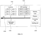
- FIG. 13 is a schematic structural diagram of another server that has a CPU topology structure according to an embodiment of the present invention.
- the multipath server may include a CPU topology 1301, an input/output interface 1302, and a memory 1303 and a bus 1304 that are further shown in the figure, and may further include a controller 1305.
- the CPU topology 1301, the input/output interface 1302, the memory 1303, and the controller 1305 are connected and communicate with each other by using the bus 1304.
- a CPU topology structure of the CPU topology 1301 herein includes slots, and an independently pluggable CPU is installed in the slot. The slots are connected by using an interconnection channel, so as to form a stable third CPU topology.
- a CPU corresponding to a to-be-removed CPU generally exists in a fourth CPU topology, and slots may be reserved in the third CPU topology.
- a to-be-added CPU and a CPU corresponding to the to-be-added CPU may be installed in the reserved slots.
- the reserved slots may be distinguished from the slots in the fourth CPU topology. For example, if the to-be-added CPU and the CPU corresponding to the to-be-added CPU are considered as a CPU group, slots belonging to a same slot group may be identified by using a same identifier or a same type of identifiers, or a same group of slots may be circled in a same block on a main board, or a same group of slots may be marked by using a same color.
- CPU hot plug may be implemented without affecting stability of the CPU topology, so that a system can operate normally, thereby improving user experience.
- Further embodiments of the present invention are provided in the following. It should be noted that the numbering used in the following section does not necessarily need to comply with the numbering used in the previous sections.
- Steps of methods or algorithms described in the embodiments disclosed in this specification may be implemented by hardware, a software module executed by a processor, or a combination thereof.
- the software module may reside in a random access memory (RAM), a memory, a read-only memory (ROM), an electrically programmable ROM, an electrically erasable programmable ROM, a register, a hard disk, a removable disk, a CD-ROM, or any other form of storage medium known in the art.
Landscapes
- Engineering & Computer Science (AREA)
- Theoretical Computer Science (AREA)
- General Engineering & Computer Science (AREA)
- Physics & Mathematics (AREA)
- General Physics & Mathematics (AREA)
- Quality & Reliability (AREA)
- Software Systems (AREA)
- Computer Hardware Design (AREA)
- Hardware Redundancy (AREA)
Applications Claiming Priority (3)
| Application Number | Priority Date | Filing Date | Title |
|---|---|---|---|
| CN201610016926.9A CN105700975B (zh) | 2016-01-08 | 2016-01-08 | 一种中央处理器cpu热移除、热添加方法及装置 |
| PCT/CN2016/098741 WO2017118080A1 (fr) | 2016-01-08 | 2016-09-12 | Procédé et dispositif de suppression thermique et d'ajout thermique destinés à une unité centrale de traitement (cpu) |
| EP16883210.3A EP3306476B1 (fr) | 2016-01-08 | 2016-09-12 | Procédé et dispositif de suppression et d'ajout a chaud d'une unité centrale de traitement (cpu) |
Related Parent Applications (1)
| Application Number | Title | Priority Date | Filing Date |
|---|---|---|---|
| EP16883210.3A Division EP3306476B1 (fr) | 2016-01-08 | 2016-09-12 | Procédé et dispositif de suppression et d'ajout a chaud d'une unité centrale de traitement (cpu) |
Publications (2)
| Publication Number | Publication Date |
|---|---|
| EP3767470A1 true EP3767470A1 (fr) | 2021-01-20 |
| EP3767470B1 EP3767470B1 (fr) | 2022-02-23 |
Family
ID=56226220
Family Applications (2)
| Application Number | Title | Priority Date | Filing Date |
|---|---|---|---|
| EP16883210.3A Active EP3306476B1 (fr) | 2016-01-08 | 2016-09-12 | Procédé et dispositif de suppression et d'ajout a chaud d'une unité centrale de traitement (cpu) |
| EP20159979.2A Active EP3767470B1 (fr) | 2016-01-08 | 2016-09-12 | Procédé et dispositif de retrait à chaud d'une unité centrale de traitement et procédé et dispositif d'ajout à chaud d'une unité centrale de traitement |
Family Applications Before (1)
| Application Number | Title | Priority Date | Filing Date |
|---|---|---|---|
| EP16883210.3A Active EP3306476B1 (fr) | 2016-01-08 | 2016-09-12 | Procédé et dispositif de suppression et d'ajout a chaud d'une unité centrale de traitement (cpu) |
Country Status (5)
| Country | Link |
|---|---|
| US (1) | US10846186B2 (fr) |
| EP (2) | EP3306476B1 (fr) |
| CN (1) | CN105700975B (fr) |
| ES (1) | ES2793006T3 (fr) |
| WO (1) | WO2017118080A1 (fr) |
Families Citing this family (9)
| Publication number | Priority date | Publication date | Assignee | Title |
|---|---|---|---|---|
| CN105700975B (zh) | 2016-01-08 | 2019-05-24 | 华为技术有限公司 | 一种中央处理器cpu热移除、热添加方法及装置 |
| CN108616366A (zh) * | 2016-12-09 | 2018-10-02 | 华为技术有限公司 | 业务处理单元管理方法及装置 |
| CN106933575B (zh) * | 2017-02-27 | 2020-08-14 | 苏州浪潮智能科技有限公司 | 一种带外识别服务器资产信息的系统及方法 |
| CN107547451B (zh) * | 2017-05-31 | 2020-04-03 | 新华三信息技术有限公司 | 一种多路服务器、cpu连接方法及装置 |
| US10628338B2 (en) * | 2018-03-21 | 2020-04-21 | Lenovo Enterprise Solutions (Singapore) Pte. Ltd. | Selection of a location for installation of a CPU in a compute node using predicted performance scores |
| WO2020000354A1 (fr) * | 2018-06-29 | 2020-01-02 | Intel Corporation | Remplacement à chaud de cpu |
| CN109189699B (zh) * | 2018-09-21 | 2022-03-22 | 郑州云海信息技术有限公司 | 多路服务器通信方法、系统、中间控制器及可读存储介质 |
| CN109491947B (zh) * | 2018-11-14 | 2021-12-03 | 郑州云海信息技术有限公司 | 一种pcie外接卡热移除信息的发送方法及相关装置 |
| CN110764829B (zh) * | 2019-09-21 | 2022-07-08 | 苏州浪潮智能科技有限公司 | 一种多路服务器cpu隔离方法及系统 |
Citations (4)
| Publication number | Priority date | Publication date | Assignee | Title |
|---|---|---|---|---|
| US6282596B1 (en) * | 1999-03-25 | 2001-08-28 | International Business Machines Corporation | Method and system for hot-plugging a processor into a data processing system |
| CN1491386A (zh) * | 2001-02-09 | 2004-04-21 | 在可修复的故障后使群集器系统自动投入运行 | |
| US20070180288A1 (en) * | 2005-12-22 | 2007-08-02 | International Business Machines Corporation | Method, system and program for securing redundancy in parallel computing sytem |
| CN103425545A (zh) * | 2013-08-20 | 2013-12-04 | 浪潮电子信息产业股份有限公司 | 一种多处理器服务器的系统容错方法 |
Family Cites Families (23)
| Publication number | Priority date | Publication date | Assignee | Title |
|---|---|---|---|---|
| US5367636A (en) * | 1990-09-24 | 1994-11-22 | Ncube Corporation | Hypercube processor network in which the processor indentification numbers of two processors connected to each other through port number n, vary only in the nth bit |
| US5909558A (en) * | 1997-07-31 | 1999-06-01 | Linzmeier; Daniel | Low power serial arbitration system |
| US6948021B2 (en) * | 2000-11-16 | 2005-09-20 | Racemi Systems | Cluster component network appliance system and method for enhancing fault tolerance and hot-swapping |
| US6990545B2 (en) * | 2003-04-28 | 2006-01-24 | International Business Machines Corporation | Non-disruptive, dynamic hot-plug and hot-remove of server nodes in an SMP |
| US7739685B2 (en) * | 2005-01-06 | 2010-06-15 | International Business Machines Corporation | Decoupling a central processing unit from its tasks |
| US7770061B2 (en) * | 2005-06-02 | 2010-08-03 | Avaya Inc. | Fault recovery in concurrent queue management systems |
| CN101878620A (zh) * | 2007-11-29 | 2010-11-03 | 英特尔公司 | 在基于链路的系统中修改系统路由信息 |
| US20090144476A1 (en) * | 2007-12-04 | 2009-06-04 | Xiaohua Cai | Hot plug in a link based system |
| CN101216793A (zh) * | 2008-01-18 | 2008-07-09 | 华为技术有限公司 | 一种多处理器系统故障恢复的方法及装置 |
| US20110179311A1 (en) * | 2009-12-31 | 2011-07-21 | Nachimuthu Murugasamy K | Injecting error and/or migrating memory in a computing system |
| CN102232218B (zh) * | 2011-06-24 | 2013-04-24 | 华为技术有限公司 | 计算机子系统和计算机系统 |
| WO2012149714A1 (fr) * | 2011-08-25 | 2012-11-08 | 华为技术有限公司 | Procédé de commutation de liaison de contrôleur de nœud, système processeur et nœud |
| CN103188059A (zh) * | 2011-12-28 | 2013-07-03 | 华为技术有限公司 | 快速通道互联系统中数据包重传方法、装置和系统 |
| WO2013145255A1 (fr) * | 2012-03-30 | 2013-10-03 | 富士通株式会社 | Dispositif de commande fournissant de l'énergie, dispositif de nœud de relais, système de réseau ad hoc filaire et procédé de commande de fourniture d'énergie |
| US9164809B2 (en) * | 2012-09-04 | 2015-10-20 | Red Hat Israel, Ltd. | Virtual processor provisioning in virtualized computer systems |
| CN103412836B (zh) * | 2013-06-26 | 2016-08-10 | 华为技术有限公司 | 热插拔处理方法、装置以及系统 |
| JP6103060B2 (ja) * | 2013-07-11 | 2017-03-29 | 富士通株式会社 | 管理装置、管理方法及びプログラム |
| CN103699444B (zh) * | 2013-12-17 | 2017-03-15 | 华为技术有限公司 | 中央处理器热插拔的实现方法及装置 |
| JP6337606B2 (ja) * | 2014-05-15 | 2018-06-06 | 富士通株式会社 | 情報処理装置、経路決定方法及びプログラム |
| CN104375881B (zh) * | 2014-10-28 | 2017-11-14 | 江苏中科梦兰电子科技有限公司 | 龙芯处理器的主核热插拔方法 |
| CN106104505B (zh) * | 2015-12-29 | 2020-02-21 | 华为技术有限公司 | 一种cpu及多cpu系统管理方法 |
| CN105700975B (zh) * | 2016-01-08 | 2019-05-24 | 华为技术有限公司 | 一种中央处理器cpu热移除、热添加方法及装置 |
| US10503684B2 (en) * | 2016-07-01 | 2019-12-10 | Intel Corporation | Multiple uplink port devices |
-
2016
- 2016-01-08 CN CN201610016926.9A patent/CN105700975B/zh active Active
- 2016-09-12 EP EP16883210.3A patent/EP3306476B1/fr active Active
- 2016-09-12 ES ES16883210T patent/ES2793006T3/es active Active
- 2016-09-12 WO PCT/CN2016/098741 patent/WO2017118080A1/fr not_active Ceased
- 2016-09-12 EP EP20159979.2A patent/EP3767470B1/fr active Active
-
2018
- 2018-01-05 US US15/863,350 patent/US10846186B2/en active Active
Patent Citations (4)
| Publication number | Priority date | Publication date | Assignee | Title |
|---|---|---|---|---|
| US6282596B1 (en) * | 1999-03-25 | 2001-08-28 | International Business Machines Corporation | Method and system for hot-plugging a processor into a data processing system |
| CN1491386A (zh) * | 2001-02-09 | 2004-04-21 | 在可修复的故障后使群集器系统自动投入运行 | |
| US20070180288A1 (en) * | 2005-12-22 | 2007-08-02 | International Business Machines Corporation | Method, system and program for securing redundancy in parallel computing sytem |
| CN103425545A (zh) * | 2013-08-20 | 2013-12-04 | 浪潮电子信息产业股份有限公司 | 一种多处理器服务器的系统容错方法 |
Also Published As
| Publication number | Publication date |
|---|---|
| US10846186B2 (en) | 2020-11-24 |
| EP3306476B1 (fr) | 2020-03-25 |
| US20180129574A1 (en) | 2018-05-10 |
| EP3306476A1 (fr) | 2018-04-11 |
| EP3306476A4 (fr) | 2018-11-07 |
| CN105700975A (zh) | 2016-06-22 |
| WO2017118080A1 (fr) | 2017-07-13 |
| CN105700975B (zh) | 2019-05-24 |
| ES2793006T3 (es) | 2020-11-12 |
| EP3767470B1 (fr) | 2022-02-23 |
Similar Documents
| Publication | Publication Date | Title |
|---|---|---|
| US10846186B2 (en) | Central processing unit CPU hot-remove method and apparatus, and central processing unit CPU hot-add method and apparatus | |
| CN108023967B (zh) | 一种数据平衡方法、装置及分布式存储系统中的管理设备 | |
| CN110096336B (zh) | 数据监控方法、装置、设备和介质 | |
| EP3418877A1 (fr) | Procédé et appareil d'écriture et de lecture de données, et système de stockage en nuage | |
| CN101980490A (zh) | 虚拟交换机和物理交换机的链路建立方法及其装置 | |
| CN105337780A (zh) | 一种服务器节点配置方法及物理节点 | |
| CN112015561B (zh) | 用于流式计算服务的方法、装置和系统 | |
| CN114168071B (zh) | 一种分布式集群扩容方法、分布式集群扩容装置及介质 | |
| CN111352803A (zh) | 业务数据处理方法、装置、设备和存储介质 | |
| JP4726915B2 (ja) | コンピュータ構成においてデバイスのクリティカル性を判断する方法及びシステム | |
| CN118511179A (zh) | 针对文本的智能表格建议和转换 | |
| CN108200038A (zh) | 一种虚拟机安全防护方法、装置、可读介质及存储控制器 | |
| CN110750219B (zh) | 存储集群的业务处理方法、装置、设备及可读存储介质 | |
| CN107896196B (zh) | 一种分配报文的方法和装置 | |
| CN115390992A (zh) | 一种虚拟机创建方法、装置、设备和存储介质 | |
| CN113934566B (zh) | 异常处理方法、装置和电子设备 | |
| CN107547451A (zh) | 一种多路服务器、cpu连接方法及装置 | |
| EP3291096B1 (fr) | Système de stockage et procédé de balayage de dispositif | |
| CN104679687A (zh) | 一种识别中断源的方法及装置 | |
| CN110837451A (zh) | 虚拟机高可用的处理方法、装置、设备和介质 | |
| CN116701716A (zh) | 基于图计算的大型数据集群系统重要性定级方法 | |
| CN116346728A (zh) | 低代码平台限流方法及装置 | |
| CN107291580A (zh) | 计算机容错系统及方法 | |
| CN118214738B (zh) | 虚拟化控制系统中网关ip地址的分配方法及装置 | |
| TWI839106B (zh) | 依發送參數決定發送順序以發送通知訊息之裝置及方法 |
Legal Events
| Date | Code | Title | Description |
|---|---|---|---|
| STAA | Information on the status of an ep patent application or granted ep patent |
Free format text: STATUS: UNKNOWN |
|
| PUAI | Public reference made under article 153(3) epc to a published international application that has entered the european phase |
Free format text: ORIGINAL CODE: 0009012 |
|
| STAA | Information on the status of an ep patent application or granted ep patent |
Free format text: STATUS: THE APPLICATION HAS BEEN PUBLISHED |
|
| AC | Divisional application: reference to earlier application |
Ref document number: 3306476 Country of ref document: EP Kind code of ref document: P |
|
| AK | Designated contracting states |
Kind code of ref document: A1 Designated state(s): AL AT BE BG CH CY CZ DE DK EE ES FI FR GB GR HR HU IE IS IT LI LT LU LV MC MK MT NL NO PL PT RO RS SE SI SK SM TR |
|
| STAA | Information on the status of an ep patent application or granted ep patent |
Free format text: STATUS: REQUEST FOR EXAMINATION WAS MADE |
|
| 17P | Request for examination filed |
Effective date: 20210519 |
|
| RBV | Designated contracting states (corrected) |
Designated state(s): AL AT BE BG CH CY CZ DE DK EE ES FI FR GB GR HR HU IE IS IT LI LT LU LV MC MK MT NL NO PL PT RO RS SE SI SK SM TR |
|
| GRAP | Despatch of communication of intention to grant a patent |
Free format text: ORIGINAL CODE: EPIDOSNIGR1 |
|
| STAA | Information on the status of an ep patent application or granted ep patent |
Free format text: STATUS: GRANT OF PATENT IS INTENDED |
|
| INTG | Intention to grant announced |
Effective date: 20211021 |
|
| GRAS | Grant fee paid |
Free format text: ORIGINAL CODE: EPIDOSNIGR3 |
|
| GRAA | (expected) grant |
Free format text: ORIGINAL CODE: 0009210 |
|
| STAA | Information on the status of an ep patent application or granted ep patent |
Free format text: STATUS: THE PATENT HAS BEEN GRANTED |
|
| AC | Divisional application: reference to earlier application |
Ref document number: 3306476 Country of ref document: EP Kind code of ref document: P |
|
| AK | Designated contracting states |
Kind code of ref document: B1 Designated state(s): AL AT BE BG CH CY CZ DE DK EE ES FI FR GB GR HR HU IE IS IT LI LT LU LV MC MK MT NL NO PL PT RO RS SE SI SK SM TR |
|
| REG | Reference to a national code |
Ref country code: GB Ref legal event code: FG4D |
|
| REG | Reference to a national code |
Ref country code: CH Ref legal event code: EP |
|
| REG | Reference to a national code |
Ref country code: DE Ref legal event code: R096 Ref document number: 602016069505 Country of ref document: DE |
|
| REG | Reference to a national code |
Ref country code: AT Ref legal event code: REF Ref document number: 1470985 Country of ref document: AT Kind code of ref document: T Effective date: 20220315 |
|
| REG | Reference to a national code |
Ref country code: IE Ref legal event code: FG4D |
|
| REG | Reference to a national code |
Ref country code: NL Ref legal event code: FP |
|
| REG | Reference to a national code |
Ref country code: LT Ref legal event code: MG9D |
|
| REG | Reference to a national code |
Ref country code: AT Ref legal event code: MK05 Ref document number: 1470985 Country of ref document: AT Kind code of ref document: T Effective date: 20220223 |
|
| PG25 | Lapsed in a contracting state [announced via postgrant information from national office to epo] |
Ref country code: SE Free format text: LAPSE BECAUSE OF FAILURE TO SUBMIT A TRANSLATION OF THE DESCRIPTION OR TO PAY THE FEE WITHIN THE PRESCRIBED TIME-LIMIT Effective date: 20220223 Ref country code: RS Free format text: LAPSE BECAUSE OF FAILURE TO SUBMIT A TRANSLATION OF THE DESCRIPTION OR TO PAY THE FEE WITHIN THE PRESCRIBED TIME-LIMIT Effective date: 20220223 Ref country code: PT Free format text: LAPSE BECAUSE OF FAILURE TO SUBMIT A TRANSLATION OF THE DESCRIPTION OR TO PAY THE FEE WITHIN THE PRESCRIBED TIME-LIMIT Effective date: 20220623 Ref country code: NO Free format text: LAPSE BECAUSE OF FAILURE TO SUBMIT A TRANSLATION OF THE DESCRIPTION OR TO PAY THE FEE WITHIN THE PRESCRIBED TIME-LIMIT Effective date: 20220523 Ref country code: LT Free format text: LAPSE BECAUSE OF FAILURE TO SUBMIT A TRANSLATION OF THE DESCRIPTION OR TO PAY THE FEE WITHIN THE PRESCRIBED TIME-LIMIT Effective date: 20220223 Ref country code: HR Free format text: LAPSE BECAUSE OF FAILURE TO SUBMIT A TRANSLATION OF THE DESCRIPTION OR TO PAY THE FEE WITHIN THE PRESCRIBED TIME-LIMIT Effective date: 20220223 Ref country code: ES Free format text: LAPSE BECAUSE OF FAILURE TO SUBMIT A TRANSLATION OF THE DESCRIPTION OR TO PAY THE FEE WITHIN THE PRESCRIBED TIME-LIMIT Effective date: 20220223 Ref country code: BG Free format text: LAPSE BECAUSE OF FAILURE TO SUBMIT A TRANSLATION OF THE DESCRIPTION OR TO PAY THE FEE WITHIN THE PRESCRIBED TIME-LIMIT Effective date: 20220523 |
|
| PG25 | Lapsed in a contracting state [announced via postgrant information from national office to epo] |
Ref country code: PL Free format text: LAPSE BECAUSE OF FAILURE TO SUBMIT A TRANSLATION OF THE DESCRIPTION OR TO PAY THE FEE WITHIN THE PRESCRIBED TIME-LIMIT Effective date: 20220223 Ref country code: LV Free format text: LAPSE BECAUSE OF FAILURE TO SUBMIT A TRANSLATION OF THE DESCRIPTION OR TO PAY THE FEE WITHIN THE PRESCRIBED TIME-LIMIT Effective date: 20220223 Ref country code: GR Free format text: LAPSE BECAUSE OF FAILURE TO SUBMIT A TRANSLATION OF THE DESCRIPTION OR TO PAY THE FEE WITHIN THE PRESCRIBED TIME-LIMIT Effective date: 20220524 Ref country code: FI Free format text: LAPSE BECAUSE OF FAILURE TO SUBMIT A TRANSLATION OF THE DESCRIPTION OR TO PAY THE FEE WITHIN THE PRESCRIBED TIME-LIMIT Effective date: 20220223 Ref country code: AT Free format text: LAPSE BECAUSE OF FAILURE TO SUBMIT A TRANSLATION OF THE DESCRIPTION OR TO PAY THE FEE WITHIN THE PRESCRIBED TIME-LIMIT Effective date: 20220223 |
|
| PG25 | Lapsed in a contracting state [announced via postgrant information from national office to epo] |
Ref country code: IS Free format text: LAPSE BECAUSE OF FAILURE TO SUBMIT A TRANSLATION OF THE DESCRIPTION OR TO PAY THE FEE WITHIN THE PRESCRIBED TIME-LIMIT Effective date: 20220623 |
|
| PG25 | Lapsed in a contracting state [announced via postgrant information from national office to epo] |
Ref country code: SM Free format text: LAPSE BECAUSE OF FAILURE TO SUBMIT A TRANSLATION OF THE DESCRIPTION OR TO PAY THE FEE WITHIN THE PRESCRIBED TIME-LIMIT Effective date: 20220223 Ref country code: SK Free format text: LAPSE BECAUSE OF FAILURE TO SUBMIT A TRANSLATION OF THE DESCRIPTION OR TO PAY THE FEE WITHIN THE PRESCRIBED TIME-LIMIT Effective date: 20220223 Ref country code: RO Free format text: LAPSE BECAUSE OF FAILURE TO SUBMIT A TRANSLATION OF THE DESCRIPTION OR TO PAY THE FEE WITHIN THE PRESCRIBED TIME-LIMIT Effective date: 20220223 Ref country code: EE Free format text: LAPSE BECAUSE OF FAILURE TO SUBMIT A TRANSLATION OF THE DESCRIPTION OR TO PAY THE FEE WITHIN THE PRESCRIBED TIME-LIMIT Effective date: 20220223 Ref country code: DK Free format text: LAPSE BECAUSE OF FAILURE TO SUBMIT A TRANSLATION OF THE DESCRIPTION OR TO PAY THE FEE WITHIN THE PRESCRIBED TIME-LIMIT Effective date: 20220223 Ref country code: CZ Free format text: LAPSE BECAUSE OF FAILURE TO SUBMIT A TRANSLATION OF THE DESCRIPTION OR TO PAY THE FEE WITHIN THE PRESCRIBED TIME-LIMIT Effective date: 20220223 |
|
| REG | Reference to a national code |
Ref country code: DE Ref legal event code: R097 Ref document number: 602016069505 Country of ref document: DE |
|
| PG25 | Lapsed in a contracting state [announced via postgrant information from national office to epo] |
Ref country code: AL Free format text: LAPSE BECAUSE OF FAILURE TO SUBMIT A TRANSLATION OF THE DESCRIPTION OR TO PAY THE FEE WITHIN THE PRESCRIBED TIME-LIMIT Effective date: 20220223 |
|
| PLBE | No opposition filed within time limit |
Free format text: ORIGINAL CODE: 0009261 |
|
| STAA | Information on the status of an ep patent application or granted ep patent |
Free format text: STATUS: NO OPPOSITION FILED WITHIN TIME LIMIT |
|
| 26N | No opposition filed |
Effective date: 20221124 |
|
| PG25 | Lapsed in a contracting state [announced via postgrant information from national office to epo] |
Ref country code: SI Free format text: LAPSE BECAUSE OF FAILURE TO SUBMIT A TRANSLATION OF THE DESCRIPTION OR TO PAY THE FEE WITHIN THE PRESCRIBED TIME-LIMIT Effective date: 20220223 |
|
| PG25 | Lapsed in a contracting state [announced via postgrant information from national office to epo] |
Ref country code: MC Free format text: LAPSE BECAUSE OF FAILURE TO SUBMIT A TRANSLATION OF THE DESCRIPTION OR TO PAY THE FEE WITHIN THE PRESCRIBED TIME-LIMIT Effective date: 20220223 |
|
| REG | Reference to a national code |
Ref country code: CH Ref legal event code: PL |
|
| REG | Reference to a national code |
Ref country code: BE Ref legal event code: MM Effective date: 20220930 |
|
| PG25 | Lapsed in a contracting state [announced via postgrant information from national office to epo] |
Ref country code: LU Free format text: LAPSE BECAUSE OF NON-PAYMENT OF DUE FEES Effective date: 20220912 |
|
| PG25 | Lapsed in a contracting state [announced via postgrant information from national office to epo] |
Ref country code: LI Free format text: LAPSE BECAUSE OF NON-PAYMENT OF DUE FEES Effective date: 20220930 Ref country code: IT Free format text: LAPSE BECAUSE OF FAILURE TO SUBMIT A TRANSLATION OF THE DESCRIPTION OR TO PAY THE FEE WITHIN THE PRESCRIBED TIME-LIMIT Effective date: 20220223 Ref country code: IE Free format text: LAPSE BECAUSE OF NON-PAYMENT OF DUE FEES Effective date: 20220912 Ref country code: FR Free format text: LAPSE BECAUSE OF NON-PAYMENT OF DUE FEES Effective date: 20220930 Ref country code: CH Free format text: LAPSE BECAUSE OF NON-PAYMENT OF DUE FEES Effective date: 20220930 |
|
| PG25 | Lapsed in a contracting state [announced via postgrant information from national office to epo] |
Ref country code: BE Free format text: LAPSE BECAUSE OF NON-PAYMENT OF DUE FEES Effective date: 20220930 |
|
| PG25 | Lapsed in a contracting state [announced via postgrant information from national office to epo] |
Ref country code: CY Free format text: LAPSE BECAUSE OF FAILURE TO SUBMIT A TRANSLATION OF THE DESCRIPTION OR TO PAY THE FEE WITHIN THE PRESCRIBED TIME-LIMIT Effective date: 20220223 |
|
| PG25 | Lapsed in a contracting state [announced via postgrant information from national office to epo] |
Ref country code: MK Free format text: LAPSE BECAUSE OF FAILURE TO SUBMIT A TRANSLATION OF THE DESCRIPTION OR TO PAY THE FEE WITHIN THE PRESCRIBED TIME-LIMIT Effective date: 20220223 Ref country code: HU Free format text: LAPSE BECAUSE OF FAILURE TO SUBMIT A TRANSLATION OF THE DESCRIPTION OR TO PAY THE FEE WITHIN THE PRESCRIBED TIME-LIMIT; INVALID AB INITIO Effective date: 20160912 |
|
| PG25 | Lapsed in a contracting state [announced via postgrant information from national office to epo] |
Ref country code: TR Free format text: LAPSE BECAUSE OF FAILURE TO SUBMIT A TRANSLATION OF THE DESCRIPTION OR TO PAY THE FEE WITHIN THE PRESCRIBED TIME-LIMIT Effective date: 20220223 |
|
| PG25 | Lapsed in a contracting state [announced via postgrant information from national office to epo] |
Ref country code: MT Free format text: LAPSE BECAUSE OF FAILURE TO SUBMIT A TRANSLATION OF THE DESCRIPTION OR TO PAY THE FEE WITHIN THE PRESCRIBED TIME-LIMIT Effective date: 20220223 |
|
| PGFP | Annual fee paid to national office [announced via postgrant information from national office to epo] |
Ref country code: NL Payment date: 20250814 Year of fee payment: 10 |
|
| PGFP | Annual fee paid to national office [announced via postgrant information from national office to epo] |
Ref country code: DE Payment date: 20250730 Year of fee payment: 10 |
|
| PGFP | Annual fee paid to national office [announced via postgrant information from national office to epo] |
Ref country code: GB Payment date: 20250731 Year of fee payment: 10 |