EP3767546B1 - Dispositif de commande de moteur et programme de réseau neuronal fourni avec ce dispositif - Google Patents
Dispositif de commande de moteur et programme de réseau neuronal fourni avec ce dispositif Download PDFInfo
- Publication number
- EP3767546B1 EP3767546B1 EP20185927.9A EP20185927A EP3767546B1 EP 3767546 B1 EP3767546 B1 EP 3767546B1 EP 20185927 A EP20185927 A EP 20185927A EP 3767546 B1 EP3767546 B1 EP 3767546B1
- Authority
- EP
- European Patent Office
- Prior art keywords
- layer
- lyr
- fully connected
- engine
- data
- Prior art date
- Legal status (The legal status is an assumption and is not a legal conclusion. Google has not performed a legal analysis and makes no representation as to the accuracy of the status listed.)
- Active
Links
Images


Classifications
-
- F—MECHANICAL ENGINEERING; LIGHTING; HEATING; WEAPONS; BLASTING
- F02—COMBUSTION ENGINES; HOT-GAS OR COMBUSTION-PRODUCT ENGINE PLANTS
- F02D—CONTROLLING COMBUSTION ENGINES
- F02D41/00—Electrical control of supply of combustible mixture or its constituents
- F02D41/02—Circuit arrangements for generating control signals
- F02D41/14—Introducing closed-loop corrections
- F02D41/1401—Introducing closed-loop corrections characterised by the control or regulation method
- F02D41/1402—Adaptive control
-
- F—MECHANICAL ENGINEERING; LIGHTING; HEATING; WEAPONS; BLASTING
- F02—COMBUSTION ENGINES; HOT-GAS OR COMBUSTION-PRODUCT ENGINE PLANTS
- F02D—CONTROLLING COMBUSTION ENGINES
- F02D41/00—Electrical control of supply of combustible mixture or its constituents
- F02D41/0002—Controlling intake air
- F02D41/0007—Controlling intake air for control of turbo-charged or super-charged engines
-
- F—MECHANICAL ENGINEERING; LIGHTING; HEATING; WEAPONS; BLASTING
- F02—COMBUSTION ENGINES; HOT-GAS OR COMBUSTION-PRODUCT ENGINE PLANTS
- F02D—CONTROLLING COMBUSTION ENGINES
- F02D41/00—Electrical control of supply of combustible mixture or its constituents
- F02D41/02—Circuit arrangements for generating control signals
- F02D41/14—Introducing closed-loop corrections
- F02D41/1401—Introducing closed-loop corrections characterised by the control or regulation method
- F02D41/1405—Neural network control
-
- G—PHYSICS
- G05—CONTROLLING; REGULATING
- G05B—CONTROL OR REGULATING SYSTEMS IN GENERAL; FUNCTIONAL ELEMENTS OF SUCH SYSTEMS; MONITORING OR TESTING ARRANGEMENTS FOR SUCH SYSTEMS OR ELEMENTS
- G05B13/00—Adaptive control systems, i.e. systems automatically adjusting themselves to have a performance which is optimum according to some preassigned criterion
- G05B13/02—Adaptive control systems, i.e. systems automatically adjusting themselves to have a performance which is optimum according to some preassigned criterion electric
- G05B13/0265—Adaptive control systems, i.e. systems automatically adjusting themselves to have a performance which is optimum according to some preassigned criterion electric the criterion being a learning criterion
- G05B13/027—Adaptive control systems, i.e. systems automatically adjusting themselves to have a performance which is optimum according to some preassigned criterion electric the criterion being a learning criterion using neural networks only
-
- G—PHYSICS
- G05—CONTROLLING; REGULATING
- G05B—CONTROL OR REGULATING SYSTEMS IN GENERAL; FUNCTIONAL ELEMENTS OF SUCH SYSTEMS; MONITORING OR TESTING ARRANGEMENTS FOR SUCH SYSTEMS OR ELEMENTS
- G05B13/00—Adaptive control systems, i.e. systems automatically adjusting themselves to have a performance which is optimum according to some preassigned criterion
- G05B13/02—Adaptive control systems, i.e. systems automatically adjusting themselves to have a performance which is optimum according to some preassigned criterion electric
- G05B13/04—Adaptive control systems, i.e. systems automatically adjusting themselves to have a performance which is optimum according to some preassigned criterion electric involving the use of models or simulators
- G05B13/041—Adaptive control systems, i.e. systems automatically adjusting themselves to have a performance which is optimum according to some preassigned criterion electric involving the use of models or simulators in which a variable is automatically adjusted to optimise the performance
-
- G—PHYSICS
- G06—COMPUTING OR CALCULATING; COUNTING
- G06N—COMPUTING ARRANGEMENTS BASED ON SPECIFIC COMPUTATIONAL MODELS
- G06N3/00—Computing arrangements based on biological models
- G06N3/02—Neural networks
- G06N3/04—Architecture, e.g. interconnection topology
- G06N3/044—Recurrent networks, e.g. Hopfield networks
- G06N3/0442—Recurrent networks, e.g. Hopfield networks characterised by memory or gating, e.g. long short-term memory [LSTM] or gated recurrent units [GRU]
-
- G—PHYSICS
- G06—COMPUTING OR CALCULATING; COUNTING
- G06N—COMPUTING ARRANGEMENTS BASED ON SPECIFIC COMPUTATIONAL MODELS
- G06N3/00—Computing arrangements based on biological models
- G06N3/02—Neural networks
- G06N3/04—Architecture, e.g. interconnection topology
- G06N3/045—Combinations of networks
-
- G—PHYSICS
- G06—COMPUTING OR CALCULATING; COUNTING
- G06N—COMPUTING ARRANGEMENTS BASED ON SPECIFIC COMPUTATIONAL MODELS
- G06N3/00—Computing arrangements based on biological models
- G06N3/02—Neural networks
- G06N3/04—Architecture, e.g. interconnection topology
- G06N3/048—Activation functions
-
- G—PHYSICS
- G06—COMPUTING OR CALCULATING; COUNTING
- G06N—COMPUTING ARRANGEMENTS BASED ON SPECIFIC COMPUTATIONAL MODELS
- G06N3/00—Computing arrangements based on biological models
- G06N3/02—Neural networks
- G06N3/08—Learning methods
- G06N3/082—Learning methods modifying the architecture, e.g. adding, deleting or silencing nodes or connections
-
- G—PHYSICS
- G06—COMPUTING OR CALCULATING; COUNTING
- G06N—COMPUTING ARRANGEMENTS BASED ON SPECIFIC COMPUTATIONAL MODELS
- G06N3/00—Computing arrangements based on biological models
- G06N3/02—Neural networks
- G06N3/08—Learning methods
- G06N3/084—Backpropagation, e.g. using gradient descent
-
- G—PHYSICS
- G06—COMPUTING OR CALCULATING; COUNTING
- G06N—COMPUTING ARRANGEMENTS BASED ON SPECIFIC COMPUTATIONAL MODELS
- G06N3/00—Computing arrangements based on biological models
- G06N3/02—Neural networks
- G06N3/08—Learning methods
- G06N3/09—Supervised learning
-
- G—PHYSICS
- G06—COMPUTING OR CALCULATING; COUNTING
- G06N—COMPUTING ARRANGEMENTS BASED ON SPECIFIC COMPUTATIONAL MODELS
- G06N5/00—Computing arrangements using knowledge-based models
- G06N5/04—Inference or reasoning models
- G06N5/046—Forward inferencing; Production systems
-
- F—MECHANICAL ENGINEERING; LIGHTING; HEATING; WEAPONS; BLASTING
- F02—COMBUSTION ENGINES; HOT-GAS OR COMBUSTION-PRODUCT ENGINE PLANTS
- F02B—INTERNAL-COMBUSTION PISTON ENGINES; COMBUSTION ENGINES IN GENERAL
- F02B37/00—Engines characterised by provision of pumps driven at least for part of the time by exhaust
- F02B37/12—Control of the pumps
- F02B37/24—Control of the pumps by using pumps or turbines with adjustable guide vanes
-
- F—MECHANICAL ENGINEERING; LIGHTING; HEATING; WEAPONS; BLASTING
- F02—COMBUSTION ENGINES; HOT-GAS OR COMBUSTION-PRODUCT ENGINE PLANTS
- F02D—CONTROLLING COMBUSTION ENGINES
- F02D41/00—Electrical control of supply of combustible mixture or its constituents
- F02D41/02—Circuit arrangements for generating control signals
- F02D41/14—Introducing closed-loop corrections
- F02D41/1401—Introducing closed-loop corrections characterised by the control or regulation method
- F02D2041/141—Introducing closed-loop corrections characterised by the control or regulation method using a feed-forward control element
-
- F—MECHANICAL ENGINEERING; LIGHTING; HEATING; WEAPONS; BLASTING
- F02—COMBUSTION ENGINES; HOT-GAS OR COMBUSTION-PRODUCT ENGINE PLANTS
- F02D—CONTROLLING COMBUSTION ENGINES
- F02D41/00—Electrical control of supply of combustible mixture or its constituents
- F02D41/02—Circuit arrangements for generating control signals
- F02D41/14—Introducing closed-loop corrections
- F02D41/1401—Introducing closed-loop corrections characterised by the control or regulation method
- F02D2041/1433—Introducing closed-loop corrections characterised by the control or regulation method using a model or simulation of the system
-
- F—MECHANICAL ENGINEERING; LIGHTING; HEATING; WEAPONS; BLASTING
- F02—COMBUSTION ENGINES; HOT-GAS OR COMBUSTION-PRODUCT ENGINE PLANTS
- F02D—CONTROLLING COMBUSTION ENGINES
- F02D2200/00—Input parameters for engine control
- F02D2200/02—Input parameters for engine control the parameters being related to the engine
- F02D2200/04—Engine intake system parameters
- F02D2200/0406—Intake manifold pressure
-
- F—MECHANICAL ENGINEERING; LIGHTING; HEATING; WEAPONS; BLASTING
- F02—COMBUSTION ENGINES; HOT-GAS OR COMBUSTION-PRODUCT ENGINE PLANTS
- F02D—CONTROLLING COMBUSTION ENGINES
- F02D41/00—Electrical control of supply of combustible mixture or its constituents
- F02D41/0025—Controlling engines characterised by use of non-liquid fuels, pluralities of fuels, or non-fuel substances added to the combustible mixtures
- F02D41/0047—Controlling exhaust gas recirculation [EGR]
- F02D41/0065—Specific aspects of external EGR control
-
- Y—GENERAL TAGGING OF NEW TECHNOLOGICAL DEVELOPMENTS; GENERAL TAGGING OF CROSS-SECTIONAL TECHNOLOGIES SPANNING OVER SEVERAL SECTIONS OF THE IPC; TECHNICAL SUBJECTS COVERED BY FORMER USPC CROSS-REFERENCE ART COLLECTIONS [XRACs] AND DIGESTS
- Y02—TECHNOLOGIES OR APPLICATIONS FOR MITIGATION OR ADAPTATION AGAINST CLIMATE CHANGE
- Y02T—CLIMATE CHANGE MITIGATION TECHNOLOGIES RELATED TO TRANSPORTATION
- Y02T10/00—Road transport of goods or passengers
- Y02T10/10—Internal combustion engine [ICE] based vehicles
- Y02T10/12—Improving ICE efficiencies
Definitions
- the present invention relates to an engine control device and a neural network program provided therein.
- An engine control device includes a controller for computing a manipulated variable by which to bring a difference between a controlled variable and a target controlled variable of an engine close to zero, and an engine estimation unit for estimating the state of the engine. Instead of measuring the controlled variable of the engine, the engine estimation unit estimates the controlled variable of the engine and inputs the estimated controlled variable of the engine into the controller.
- the engine estimation unit includes an engine model realized using a neural network, for example.
- the engine model receives the manipulated variable computed by the controller, data indicating the state of the engine, and so on, and estimates the controlled variable of the engine.
- the engine model realized by the neural network preforms a learning using training data including manipulated variables and controlled variables corresponding to thereto acquired by actually operating the engine. During the learning process, internal parameters of the neural network are adjusted so that the engine model can estimate the actual state of the engine.
- the state of the engine at the current time is affected by past states.
- the manipulated variable MV, the engine internal state data ENG_DATA, and the external environment data ENV_DATA input into the neural network forming the engine model 12 are time series data.
- the neural network is a recurrent neural network in which a hidden layer between the input layer and the output layer is provided with a return path. A past state generated by the hidden layer having the return path is returned (made recurrent) along the return path and input into the hidden layer having the return path together with the state at the current time. By including the return path, it is possible to construct an engine model that considers a feature of input data that vary over time.
- the return path RC provided in the hidden layer MID_LYR returns an output h(t-1) of the hidden layer to the input side of the hidden layer.
- Each neuron of the hidden layer computes a sum of products by adding together products of the recurrent input h(t-1) and a weight U, as the input x(t) from the input layer. Further, each neuron outputs the value h(t) acquired by activating the sum of products using the activation function.
- a fully connected layer having a return path extracts a feature that is based on states at the current time t and past times t-1, t-2, ....
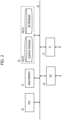
- FIG. 4 is a view illustrating an example configuration of a neural network according to a first embodiment.
- the neural network of FIG. 4 includes an input layer IN_LYR to which input data x(t) are input, an output layer OUT_LYR from which output data y(t) are output, and hidden layers MID_LYR between the input layer and the output layer.
- the hidden layers MID_LYR include a first hidden layer MID_LYR_1 including a fully connected layer F_CNCT_LYR, and a second hidden layer MID_LYR_2 including a layer RCRT_LYR having a return path.
- the fully connected layer F_CNCT_LYR is provided between the input layer IN_LYR and the layer RCRT_LYR having the return path.
- the neural network according to the first embodiment is a model of a gasoline or diesel engine, for example.
- the input data x(t) input into the input layer include at least one of the high-pressure EGR opening, the low-pressure EGR opening, the throttle opening, and the turbine vane opening, which are the manipulated variable MV.
- the input data x(t) may also include the engine internal state data ENG_DATA, such as the engine rotation speed, and the external environment data ENV_DATA, such as the external temperature or pressure.
- the output data y(t) output from the output layer include at least one of the fresh air amount, the intake air pressure, and the NOx concentration of the exhaust gas, which are the controlled variable CV.
- the input data x(t) and the output data y(t) are both time series data.
- FIG. 5 is a view illustrating an example configuration of a fully connected layer.
- a network 100 illustrated on the left side of FIG. 5 includes a fully connected layer F_CNCT_LYR, a preceding layer LYR_10, and a following layer LYR_11.
- the preceding layer LYR_10 has four neurons NR, for example, and the neurons NR respectively output elements d 1 to d 4 of data d to the neurons NR of the fully connected layer F_CNCT_LYR.
- the other two neurons of the fully connected layer F_CNCT_LYR compute data q 2 , q 3 in accordance with expression (5), convert the data q 2 , q 3 using the activation function f in accordance with expression (6), and output data h 2 , h 3 .
- the above operations are performed based on weights w and biases b associated with links LK1 between the neurons NR on the fully connected layer F_CNCT_LYR and the 4 neurons NR of the preceding layer LYR_10.
- the output data h 1 to h 3 of the fully connected layer are associated with all of the neurons NR of the following layer LYR_11 by links LK2, whereupon each neuron of the following layer performs similar operations to the fully connected layer. The operations performed on the following layer will not be described.
- a fully connected layer provided in a neural network performs the above operations on input data of training data. Parameters such as the weight and the bias are then adjusted so as to minimize an error between the output data computed on the output layer and the correct answer data of the training data.
- the fully connected layer has a function for extracting a feature of the input data for minimizing the error.
- the fully connected layer F_CNCT_LYR includes a first layer L1 corresponding to the operations of expression (5) above, and a second layer L2 corresponding to the operations of expression (6).
- the fully connected layer F_CNCT_LYR will be depicted using this notation.
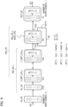
- FIG. 6 is a view illustrating the configuration of the neural network according to the first embodiment.
- the fully connected layer, the layer having the return path, and the output layer of the neural network illustrated in FIG. 4 are depicted using the notation of the fully connected layer of FIG. 5 .
- the neural network of FIG. 6 similarly to the neural network of FIG. 4 , includes the input layer IN_LYR to which the input data x(t) are input, the output layer OUT_LYR from which the output data y(t) are output, and the hidden layers MID_LYR between the input layer and the output layer.
- the hidden layers MID_LYR include the first hidden layer MID_LYR_1 including the fully connected layer F_CNCT_LYR, and the second hidden layer MID_LYR_2 including the layer RCRT_LYR having the return path.
- the first hidden layer MID_LYR_1 includes a delay layer DL_LYR that considers time delays for time series data.
- the delay layer DL_LYR inputs time series data including the data x(t) of the input data x(t) input into the input layer IN_LYR at the current time t and ⁇ -1 sets of past data x(t-dt) to x(t-( ⁇ -1) * dt) acquired at intervals of a sampling period dt.
- the fully connected layer F_CNCT_LYR is illustrated using the notation of FIG. 5 , and the activation function ACT_F thereof is a rectified linear unit (ReLU) f 2 .
- the output of the rectified linear unit f 2 is 0 when the input x is 0 or less, and x when the input x is positive.
- the output of the first hidden layer MID_LYR_1 is 0 when the sum of products (W * x + b) of the inputs, the weight and the bias is 0 or less, and as a result, unnecessary features are removed.
- the fully connected layer in which the activation function is a rectified linear unit ReLU, for example, is provided between the input layer and the layer having the return path, some of the plurality of data q 1 to q n computed respectively by the plurality of neurons on the fully connected layer become data "0", and therefore unnecessary information (data "0") is removed from the high-order (n-order) information of the input signals so that the input signals are compressed into low-order information.
- the fully connected layer can extract a feature of the input signals and output the compressed data to the layer having the return path.
- the neural network can compute output data having a small error by processing low-order information without increasing the number of neurons on the layer having the return path or the number of layers of the layer having the return path. Moreover, since the numbers of neurons and layers on the layer having the return path are small, the degree of freedom of the network is reduced, and therefore a reduction in the generalization performance of the neural network due to overlearning can be suppressed.
- a part of the output data of the fully connected layer is removed as 0 so that some of the neurons of the fully connected layer enter a state resembling a disabled state, and as a result, an effect similar to that achieved by ensemble learning can be expected.
- the activation function of the fully connected layer may be a function having similar characteristics to the aforementioned rectified linear unit ReLU. As long as the function has similar characteristics, the number of degrees of the output data of the fully connected layer can be reduced, and therefore similar effects can be expected.
- the layer RCRT_LYR having the return path on the second hidden layer MID_LYR_ 2 provided on the neural network of FIG. 6 is configured such that the return path RC is provided in a fully connected layer having first and second layers L1 and L2.
- the output data of the past time t-1, h 2 (t-1) is returned to the input in addition to the input data of the current time t, h 1 (t), and therefore both the number of neurons and the computation load of the fully connected layer having the return path are larger than those of a fully connected layer without the return path.
- the numbers of neurons and layers on the layer RCRT_LYR having the return path are small, and therefore the computation load does not increase dramatically.
- FIG. 7 is a view illustrating in detail the configurations of the delay layer DL_LYR and the fully connected layer F_CNCT_LYR within the first hidden layer MID_LYR_1 of the neural network of FIG. 6 .
- the time series data are illustrated by the following determinant.
- the first set of input data x 1 (t) of the input data x(t) are time series data including the data x 1 (t) of the current time t and ⁇ -1 sets of consecutive past data x 1 (t-dt) to x 1 (t-( ⁇ -1)*dt) acquired at intervals of the sampling period dt.
- the other sets of input data x 2 (t) to x k (t) are similar.
- the controlled variable CV and the state data ENG_DATA of the engine vary at a delay relative to change in the manipulated variable MV.
- the input x(t) at the current time t is set so that of the time series data acquired at intervals of the sampling period dt, the signal x(t) acquired at the current time t and the ⁇ -1 signals x(t-dt) to x(t-( ⁇ -1)*dt) acquired at the past times t-dt to t-( ⁇ -1)*dt can be taken into account.
- the input data x(t) x 1 (t) to x k (t) illustrated in formula 2 are input into the respective neurons of the delay layer DL_LYR sequentially, and as a result, the following data x d1 (t) of formula 3 are acquired.
- the above formula also illustrates the weight W d1 and the bias b d1 of the fully connected layer F_CNCT_LYR in relation to the output data x d1 (t) of the delay layer DL_LYR.
- the number of elements is ⁇ *k.
- Each neuron of the fully connected layer F_CNCT_LYR performs the following operations using expressions (5) and (6), illustrated above.
- each neuron of the layer RCRT_LYR having the return path within the second hidden layer MID_LYR_2 performs the following operations using expressions (1) and (2), illustrated above.
- each neuron of the output layer OUT_LYR performs the following operations using expressions (3) and (4), illustrated above.
- feature time series data h 1 (t) are extracted from the k sets of input data x 1 (t) to x k (t), which are constituted by ⁇ sets of time series data acquired at intervals of the sampling period dt.
- the time series data h 1 (t), the data amount of which has been compressed, are then input into the layer RCRT_LYR having the return path.
- the time series input data x 1 (t) to x k (t) may have different optimum numbers of steps ⁇ to be taken into consideration. Therefore, the respective numbers of steps ⁇ k of the time series input data x 1 (t) to x k (t) may be set at different numbers.
- the number of neurons on the delay layer DL_LYR is set at ⁇ i .
- ⁇ i is the cumulative number of ⁇ 1 to ⁇ k .
- the number of neurons on the fully connected layer F_CNCT_LYR of the first hidden layer MID_LYR_1 may either be set likewise at ⁇ i or at any other desired number n.
- FIG. 8 is a view depicting a flowchart of a neural network program according to the first embodiment.
- the processor 30 of the engine control device illustrated in FIG. 2 executes the neural network program 38 to perform the operations of a neural network 12 that is the engine model illustrated in FIG. 1 . These operations are as described below.
- the operations executed by the processor 30 include operations of a learning process and operations of an inference process.
- the processor executes processing steps S1 to S6 on all training data. More specifically, first, the processor receives the input data x(t) of the training data (S1). As a result, the plurality of time series input data x 1 (t) to x k (t) are input into the delay layer DL_LYR from the input layer IN_LYR.
- the processor executes operations in each neuron of the fully connected layer F_CNCT_LYR (S2).
- the arithmetic expressions in this case are expressions (5') and (6'), illustrated above.
- the processor executes operations in each neuron of the layer RCRT_LYR having the return path (S3).
- the arithmetic expressions in this case are expressions (1') and (2'), illustrated above.
- the processor executes operations in each neuron of the output layer OUT_LYR (S4).
- the arithmetic expressions in this case are expressions (3') and (4'), illustrated above.
- the above processing corresponds to feedforward processing.
- the processor then computes an error function from the output data of the output layer and the correct answer data of the training data (S5), and using a gradient method, for example, adjusts the parameters, weights w, and biases b, c of each layer so as to reduce the error function (S6).
- the parameters of a recurrent neural network that handles time series data are adjusted using a method of error backpropagation through time.
- the parameter adjustment operation S6 may be a processing to backpropagate the error between the output data of the output layer and the correct answer data of the training data and update the parameters to new parameters using a gradient method.
- the processor inputs input data x(t) for the inference and inputs the plurality of time series input data x 1 (t) to x k (t) into the delay layer DL_LYR (S7).
- the processor then executes operations in the respective neurons of the fully connected layer F_CNCT_LYR (S2s), executes operations in each neuron of the layer having the return path (S3s), and executes operations in each neuron of the output layer OUT_LYR (S4s).
- These operations S2s, S3s, S4s are identical to the operations S2, S3, S4 performed during the learning process.
- the inference operations described above are repeated until inference is complete.
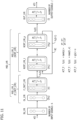
- FIG. 9 is a view illustrating an example configuration of a neural network according to a second embodiment.
- the neural network of FIG. 9 similarly to the first embodiment illustrated in FIG. 6 , includes the input layer IN_LYR to which the input data x(t) are input, the output layer OUT_LYR from which the output data y(t) are output, and the hidden layers MID_LYR between the input layer and the output layer.
- the hidden layers MID_LYR include the first hidden layer MID_LYR_1 including the delay layer DL_LYR and the fully connected layer F_CNCT_LYR, and the second hidden layer MID_LYR_2 including the layer RCRT_LYR having the return path.
- the first hidden layer MID_LYR_1 includes a plurality of fully connected layers F_CNCT_1 to F_CNCT_p.
- the activation function ACT_F of the fully connected layers F_CNCT_1 to F_CNCT_p-1 other than the final layer F_CNCT_LYR is the hyperbolic tangent function f 1
- the activation function ACT_F of the final fully connected layers F_CNCT_p is the rectified linear unit (ReLU) f 2 . It is sufficient that at least the final layer of the plurality of fully connected layers uses the ReLU function, but ReLU may also be used as the activation function of the fully connected layers other than the final layer.
- FIGS. 9 and 10 the numbers of neurons on the respective layers are indicated in parentheses.
- the plurality of fully connected layers F_CNCT_1 to F_CNCT_p are provided between the input layer IN_LYR and the layer RCRT_LYR having the return path.
- the plurality of fully connected layers appropriately extract the feature of the input data, which are constituted by time series data, and the data at or below 0 are all converted to 0 by the activation function ReLU of the final layer of the plurality of fully connected layers.
- useful information having a feature compressed into a lower order is output to the layer having the return path.
- FIG. 10 is a view illustrating in detail the configurations of the delay layer DL_LYR and the fully connected layer F_CNCT_LYR within the first hidden layer MID_LYR_1 of the neural network of FIG. 9 .
- the first hidden layer MID_LYR_1 includes the plurality of fully connected layers F_CNCT_1 to F_CNCT_p.
- the delay layer DL_LYR within the first hidden layer MID_LYR_1, the layer RCRT_LYR having the return path within the second hidden layer MID_LYR_2, and the output layer OUT_LYR are identical to FIG. 7 .
- the processor executes the operations illustrated in FIG. 8 .
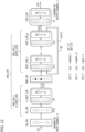
- FIG. 11 is a view illustrating an example configuration of a neural network according to a third embodiment.
- This neural network similarly to the neural networks of the first and second embodiments, includes the input layer IN_LYR to which the input data x(t) are input, the output layer OUT_LYR from which the output data y(t) are output, and the hidden layers MID_LYR between the input layer and the output layer.
- the hidden layers MID_LYR include the first hidden layer MID_LYR_1 including the delay layer DL_LYR and the fully connected layer F_CNCT_LYR, and the second hidden layer MID_LYR_2 including the layer RCRT_LYR having the return path.
- the second hidden layer MID_LYR_2 includes a plurality of layers RCRT_1 to RCRT_p having a return path, each of which is constituted by a fully connected layer.
- the output h 2 (t-1) of the final layer RCRT_p of the plurality of layers RCRT_1 to RCRT_p having the return path is input into the input of the starting layer RCRT_1 along the return path RC.
- the activation function ACT_F of the plurality of layers RCRT_1 to RCRT_p having the return path is the hyperbolic tangent function f 1 , for example.
- the plurality of layers RCRT_1 to RCRT_p having the return path are similar to the fully connected layer of FIG. 5 in that each includes a first layer L1 and a second layer L2.
- the processor executes the operations illustrated in FIG. 8 .
- FIG. 12 is a view illustrating an example configuration of a neural network according to a fourth embodiment.
- the neural network illustrated in FIG. 12 similarly to the third embodiment illustrated in FIG. 11 , includes the input layer IN_LYR to which the input data x(t) are input, the output layer OUT_LYR from which the output data y(t) are output, and the hidden layers MID_LYR between the input layer and the output layer.
- the hidden layers MID_LYR include the first hidden layer MID_LYR_1 including the delay layer DL_LYR and the fully connected layer F_CNCT_LYR, and the second hidden layer MID_LYR_2 including a plurality of layers RCRT_LYR having a return path.
- a dropout layer DRP_LYR is provided between the first hidden layer MID_LYR_1 and the second hidden layer MID_LYR_2.
- the dropout ratio of the dropout layer is 0.01% to 50%, for example, and more preferably 1% to 50%.
- the processor selects a predetermined proportion of the plurality of neurons in the dropout layer at random, disables the unselected neurons (the black circles in the figure), and performs parameter update processing using a neural network constituted by the selected neurons (the white circles in the figure). In other words, operations are performed as if the disabled neurons did not exist.
- the processor performs this selection either in minibatches or every time the update processing is performed, thereby modifying the disabled neurons.
- the dropout ratio is the ratio of disabled neurons.
- the processor performs operations after enabling all of the neurons in the dropout layer.
- the processor executes the operations illustrated in FIG. 8 . Note, however, that during the operations performed on the neurons in the dropout layer, the neurons are disabled at random, as described above.
- the number of neurons used during learning can be limited, thereby forcibly reducing the degree of freedom of the neural network so as to avoid overlearning, and as a result, the generalization performance is improved. Further, by disabling the neurons at random, learning is substantially performed by each of a plurality of neural networks so that during inference, an identical effect to that obtained by averaging the operation results of a plurality of neural networks is achieved, and as a result, equivalent effects to those obtained by ensemble learning are thought to be achieved. Accordingly, an improvement in the inference precision can be expected.
- FIG. 13 is a view illustrating an example configuration of a neural network according to a fifth embodiment.
- a neural network illustrated in FIG. 13 , in contrast to the second embodiment illustrated in FIG. 9 , one or a plurality of third hidden layers MID_LYR_3, each including a fully connected layer F_CNCT_LYR_3, are provided between the second hidden layer MID_LYR_2 and the output layer OUT_LYR.
- FIG. 13 is identical to FIG. 9 .
- the activation function ACT_F of the added fully connected layer F_CNCT_LYR_3 is the hyperbolic tangent function f 1 , for example.
- At least one of or both of a chirp signal capable of continuously varying a frequency component and an amplitude pseudo-random bit sequence (APRBS) signal obtained by randomly combining amplitudes of rectangular waves, for example, are used as the training data.
- APRBS amplitude pseudo-random bit sequence
- the time series data of the input signals are constituted by one manipulated variable among the high-pressure EGR opening, the low-pressure EGR opening, the throttle opening, and the turbine vane opening, and actual measurement values (when measurement is possible), sensor values from a software sensor, or set values are used as the time series data.
- the time series data of the input signals may also include the aforementioned data relating to the internal state of the engine and the environment on the exterior of the engine. Likewise with regard to these input signals, actual measurement values (when measurement is possible), sensor values from a software sensor, or set values are used.
- outputs of a fresh air amount sensor, an intake air pressure sensor, and a NOx sensor of an actual engine, or outputs of corresponding software sensors are used as the time series data of the output signal that is the controlled variable.
- FIG. 14 is a view illustrating examples of chirp signals.
- FIG. 14 illustrates examples of chirp signals for an engine rotation speed, a fuel injection amount, the EGR opening, and a main injection period. All of the signals have varying frequency components.
- FIG. 15 is a view illustrating examples of APRBS signals. Similarly to the chirp signals, FIG. 15 illustrates examples of APRBS signals for the engine rotation speed, the fuel injection amount, the EGR opening, and the main injection period. As depicted on the figure, each APRBS signal has a rectangular waveform with a pseudo-randomly varying amplitude.
- a process in which learning is performed using training data of the chirp signals and a process in which learning is performed using training data of the APRBS signals are either performed alternately or switched appropriately, for example.
- the present inventors created a specific neural network engine model program, caused a processor to execute the program, and evaluated the precision of the engine model.
- training data and cross-validation data to be used during learning by the neural network were acquired on an engine test bench used to operate an actual engine.
- a 3L water-cooled, in-line 4-cylinder diesel engine was used as the engine.
- Signals of the training data and the cross-validation data were acquired by (1) applying operating conditions created from chirp signals and operating conditions created based on APRBS signals to the rotation speed, the fuel injection amount, the EGR opening, the turbine vane opening, and the main injection period, and (2) operating the engine test bench. Examples of these signals are as illustrated in FIGS. 14 and 15 .
- the engine rotation speed, the fuel injection amount, the EGR opening, the turbine vane opening, and the main injection period were used as the input signals that are the manipulated variable MV, and a turbine inlet pressure, a turbine outlet pressure, an intake air temperature, an intake manifold temperature, a cooling water temperature, and an excess air ratio (lambda) were used as the input signals that are the engine state data ENG_DATA, with the result that signals of a total of 11 variables were used as the input signals.
- a signal of either the NOx concentration or the fresh air amount was used as the output signal.
- the evaluated neural network includes two examples, the first example having the configuration illustrated in FIG. 6 and the second example having the configuration illustrated in FIG. 11 .
- Signals of the aforementioned 11 variables are used as the input signals, and the fresh air amount is used as the output signal.
- the respective activation functions are as illustrated in FIG. 6 .
- the number of neurons on the layer having the return path i.e. 10 is small.
- the fully connected layer F_CNCT_LYR was omitted from the neural network configuration illustrated in FIG. 6 .
- Signals of the aforementioned 11 variables are used as the input signals
- the NOx concentration is used as the output signal.
- the respective activation functions are as illustrated in FIG. 11 .
- the fully connected layer F_CNCT_LYR was omitted from the neural network configuration illustrated in FIG. 11 .
- the input signals in the two examples and the two comparative examples include 11 variables, and each variable is constituted by 5-step (5 * dt) time series data. Hence, 11 ⁇ 5 sets of data are input into the 55 neurons of the delay layer DL_LYR as the input signals.
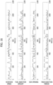
- FIG. 16 is a view illustrating examples of signal waveforms in an operating mode of the world harmonizing transient cycle (WHTC).
- the chirp signals and APRBS signals used as the input signals of the neural network are generated from the operating mode signal waveforms in FIG. 16 .
- the present inventors implemented cross-validation on the neural networks of the first example and the first comparative example using data acquired in the operating mode of WHTC, and evaluated the neural networks using a determination coefficient R 2 and an average squared error RMSE as precision evaluation indices.
- FIG. 17 is a view illustrating the evaluation results of RMSE and R 2 in the first example and the first comparative example.
- the table illustrates the respective evaluation values and indicates that in the first example, RMSE is smaller and R 2 is larger, meaning that the precision is higher.
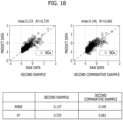
- the horizontal axis represents the correct answer value (actual measurement data) of the training data
- the vertical axis represents the inferred value (the predicted value) computed by the neural network.
- FIG. 18 is a view illustrating the evaluation results of RMSE and R 2 in the second example and the second comparative example. As illustrated on the table, in the second example, RMSE is smaller and R 2 is larger, meaning that the precision is higher. Further, the graphs in FIG. 18 indicate that the precision is higher in the second example than in the second comparative example.
- a fully connected layer for extracting a feature of the input data is provided between the input layer and the layer having the return path.
- the fully connected layer extracts a feature of the input data so that the data output to the layer having the return path are compressed.
- the inference precision can be improved without increasing the number of neurons or the number of layers on the layer having the return path, and since the numbers of neurons and layers on the layer having the return path are small, overlearning is suppressed, leading to an improvement in the generalization performance.
- a reduction in the generalization performance of a model realized by a neural network can be suppressed.
Landscapes
- Engineering & Computer Science (AREA)
- Physics & Mathematics (AREA)
- Theoretical Computer Science (AREA)
- Artificial Intelligence (AREA)
- Evolutionary Computation (AREA)
- General Engineering & Computer Science (AREA)
- Software Systems (AREA)
- General Physics & Mathematics (AREA)
- Health & Medical Sciences (AREA)
- Computational Linguistics (AREA)
- Data Mining & Analysis (AREA)
- Mathematical Physics (AREA)
- Computing Systems (AREA)
- Biophysics (AREA)
- Molecular Biology (AREA)
- General Health & Medical Sciences (AREA)
- Biomedical Technology (AREA)
- Life Sciences & Earth Sciences (AREA)
- Chemical & Material Sciences (AREA)
- Combustion & Propulsion (AREA)
- Mechanical Engineering (AREA)
- Computer Vision & Pattern Recognition (AREA)
- Medical Informatics (AREA)
- Automation & Control Theory (AREA)
- Combined Controls Of Internal Combustion Engines (AREA)
- Feedback Control In General (AREA)
Claims (10)
- Dispositif (10) de commande de moteur comprenant :un processeur (30) configuré pour mettre en œuvre un programme de réseau neuronal (38) pour mettre en œuvre des opérations d'un réseau neuronal entraîné (12), c'est-à-dire un modèle de moteur (12) qui est configuré pour recevoir une variable manipulée (MV) en entrée et est configuré pour calculer une variable commandée estimée (SP_CV) du moteur (15) correspondant à la variable manipulée ; etmettre en œuvre un programme de commande (36) qui est configuré pour calculer la variable manipulée (MV) de manière à réduire un écart (err) entre la variable commandée estimée (SP_CV) et une variable commandée cible (DV), et pour fournir en sortie la variable manipulée (MV) à un actionneur du moteur (15) afin d'amener l'actionneur à mettre en œuvre une opération correspondante, dans lequelle réseau neuronal entraîné inclut :une couche d'entrée (IN_LYR) dans laquelle une pluralité de données d'entrée incluant la variable manipulée (MV) sont entrées ;une première couche cachée (MID_LYR_1) qui inclut une première couche entièrement connectée (F_CNCT_LYR) présentant une pluralité de premiers neurones (NR) qui génèrent respectivement des premières sommes de produits (q) par l'addition de produits de la pluralité de données d'entrée (x(t), d) et de premiers paramètres de poids (W1) respectifs, et fournissent en sortie une pluralité de premières valeurs de sortie (h1(t)) par l'activation des premières sommes de produits (q) respectives sur la base d'une première fonction d'activation (f2(q)), la première fonction d'activation (f2(q)) de la première couche cachée (MID_LYR_1) étant une fonction linéaire rectifiée ;une seconde couche cachée (MID_LYR_2) qui inclut une deuxième couche entièrement connectée (RCRT_LYR) présentant une pluralité de seconds neurones (NR) qui génèrent respectivement des secondes sommes de produits (q) par l'addition de premiers produits (W2*h1(t)) de la pluralité de premières valeurs de sortie (h1(t)) acquises à un premier moment (t) et de seconds paramètres de poids (W2) respectifs et de seconds produits (U*h2(t-1)) d'une pluralité de secondes valeurs de sortie (h2(t-1)) acquises à un second moment (t-1), qui est antérieur au premier moment (t), et de troisièmes paramètres de poids (U) respectifs, et fournissent en sortie la pluralité de secondes valeurs de sortie (h2(t)) acquises au premier moment (t) par l'activation des secondes sommes de produits (q) respectives sur la base d'une seconde fonction d'activation (f1(q)), et inclut également une voie de retour (RC) sur laquelle la pluralité de secondes valeurs de sortie (h2(t-1)) acquises au second moment (t-1) sont entrées dans la deuxième couche entièrement connectée (RCRT LYR) conjointement avec les premières valeurs de sortie (h1(t)) acquises au premier moment (t) ; etune couche de sortie (OUT_LYR) à partir de laquelle la pluralité de secondes valeurs de sortie (h2(t)) acquises au premier moment (t) sont fournies en sortie en tant que variable commandée estimée (SP_CV),dans lequel la variable manipulée (MV) inclut des premières données de série temporelle de l'une quelconque parmi une ouverture d'aube de turbine d'un turbocompresseur du moteur, une ouverture de soupape d'un dispositif de recirculation des gaz d'échappement et une ouverture de papillon des gaz pour commander une quantité d'air fournie à un collecteur d'admission, etla variable commandée estimée (SP_CV) inclut des secondes données de série temporelle de l'une quelconque parmi une quantité d'air frais dans le collecteur d'admission du moteur, une pression d'air d'admission dans le collecteur d'admission, et une quantité d'oxyde d'azote contenue dans les gaz d'échappement.
- Dispositif de commande de moteur selon la revendication 1, dans lequel la première couche cachée (MID_LYR_1) inclut une pluralité de premières couches entièrement connectées (F_CNCT_LYR_1-p), et la première fonction d'activation (f2) d'une couche finale de la pluralité de premières couches entièrement connectées est la fonction linéaire rectifiée.
- Dispositif de commande de moteur selon la revendication 1, dans lequel la seconde fonction d'activation (f1) de la seconde couche cachée (MID_LYR_2) est une fonction tangente hyperbolique.
- Dispositif de commande de moteur selon la revendication 1, dans lequel la seconde couche cachée (MID_LYR_2) inclut une pluralité de secondes couches entièrement connectées, et la voie de retour (RC) est fournie entre une couche finale de la pluralité de deuxièmes couches entièrement connectées et une couche de départ de la pluralité de deuxièmes couches entièrement connectées.
- Dispositif de commande de moteur selon la revendication 1, dans lequel une couche d'abandon (DRP_LYR) sur laquelle des neurones choisis au hasard sont désactivés pendant l'apprentissage est prévue entre la première couche cachée (MID_LYR_1) et la seconde couche cachée (MID_LYR_2).
- Dispositif de commande de moteur selon la revendication 1, dans lequel une troisième couche entièrement connectée (F_CNCT_LYR_3) est prévue entre la seconde couche cachée (MID_LYR_2) et la couche de sortie (OUT_LYR), et la troisième couche entièrement connectée inclut au moins une couche entièrement connectée.
- Dispositif de commande de moteur selon la revendication 1, dans lequel les premières données de série temporelle (x (t)) sont des données de série temporelle, parmi des données de série temporelle acquises par l'obtention d'un signal de la variable manipulée à des intervalles d'une période d'échantillonnage, s'étendant d'un moment actuel (t) à un moment passé (t-(tau-1)*dt) obtenu par multiplication d'un nombre prédéterminé (tau-1) de points de données par la période d'échantillonnage (dt).
- Dispositif de commande de moteur selon la revendication 7, dans lequel les premières données de série temporelle sont constituées soit par un signal chirp présentant une fréquence variable, soit par un signal à onde rectangulaire présentant une amplitude variant de manière pseudo-aléatoire.
- Dispositif de commande de moteur selon la revendication 1, dans lequel le moteur est un moteur diesel.
- Ensemble comprenant le programme de réseau neuronal (38) et le programme de commande (36) de la revendication 1.
Applications Claiming Priority (1)
| Application Number | Priority Date | Filing Date | Title |
|---|---|---|---|
| JP2019132053A JP7231144B2 (ja) | 2019-07-17 | 2019-07-17 | エンジン制御装置及びそれが有するニューラルネットワークプログラム |
Publications (2)
| Publication Number | Publication Date |
|---|---|
| EP3767546A1 EP3767546A1 (fr) | 2021-01-20 |
| EP3767546B1 true EP3767546B1 (fr) | 2024-12-04 |
Family
ID=71620284
Family Applications (1)
| Application Number | Title | Priority Date | Filing Date |
|---|---|---|---|
| EP20185927.9A Active EP3767546B1 (fr) | 2019-07-17 | 2020-07-15 | Dispositif de commande de moteur et programme de réseau neuronal fourni avec ce dispositif |
Country Status (3)
| Country | Link |
|---|---|
| US (1) | US11199147B2 (fr) |
| EP (1) | EP3767546B1 (fr) |
| JP (1) | JP7231144B2 (fr) |
Families Citing this family (11)
| Publication number | Priority date | Publication date | Assignee | Title |
|---|---|---|---|---|
| JP6690743B1 (ja) * | 2019-01-23 | 2020-04-28 | トヨタ自動車株式会社 | 機械学習装置 |
| JP7231144B2 (ja) * | 2019-07-17 | 2023-03-01 | 株式会社トランストロン | エンジン制御装置及びそれが有するニューラルネットワークプログラム |
| JP7132196B2 (ja) * | 2019-09-17 | 2022-09-06 | 株式会社東芝 | 処理装置および推論システム |
| KR102726697B1 (ko) * | 2019-12-11 | 2024-11-06 | 현대자동차주식회사 | 빅데이터 기반 운행 정보 제공 시스템 및 방법 |
| JP2022157893A (ja) * | 2021-03-31 | 2022-10-14 | 株式会社トランストロン | エンジン制御装置、方法、およびプログラム |
| JP7628066B2 (ja) | 2021-08-26 | 2025-02-07 | 株式会社トランストロン | エンジン試験方法、エンジン試験プログラム、およびエンジン試験装置 |
| JP7759029B2 (ja) * | 2021-10-29 | 2025-10-23 | 株式会社トランストロン | 制御装置、制御方法、および制御プログラム |
| CN114934848B (zh) * | 2022-06-16 | 2023-04-07 | 哈尔滨工程大学 | 一种面向柴油机燃烧性能优化控制的模糊神经网络建模方法 |
| JP2024033635A (ja) * | 2022-08-30 | 2024-03-13 | 株式会社トランストロン | 推定方法、推定プログラム、および推定装置 |
| CN116310599B (zh) * | 2023-05-17 | 2023-08-15 | 湖北工业大学 | 基于改进cnn-pnn网络的电力变压器故障诊断方法及系统 |
| CN119272435A (zh) * | 2024-09-28 | 2025-01-07 | 天目山实验室 | 一种基于生成式模型的涡轮叶片冷却结构参数推荐方法 |
Citations (1)
| Publication number | Priority date | Publication date | Assignee | Title |
|---|---|---|---|---|
| US20100083640A1 (en) * | 2008-10-06 | 2010-04-08 | Gm Global Technology Operations, Inc. | Engine-out nox virtual sensor using cylinder pressure sensor |
Family Cites Families (27)
| Publication number | Priority date | Publication date | Assignee | Title |
|---|---|---|---|---|
| JPH0711256B2 (ja) * | 1989-09-06 | 1995-02-08 | 本田技研工業株式会社 | 内燃エンジンの制御装置 |
| JP2792633B2 (ja) * | 1990-02-09 | 1998-09-03 | 株式会社日立製作所 | 制御装置 |
| US5539638A (en) * | 1993-08-05 | 1996-07-23 | Pavilion Technologies, Inc. | Virtual emissions monitor for automobile |
| US5745653A (en) * | 1996-02-05 | 1998-04-28 | Ford Global Technologies, Inc. | Generic neural network training and processing system |
| US5752007A (en) * | 1996-03-11 | 1998-05-12 | Fisher-Rosemount Systems, Inc. | System and method using separators for developing training records for use in creating an empirical model of a process |
| DE69729981T2 (de) * | 1996-05-28 | 2004-12-16 | Honda Giken Kogyo K.K. | Gerät zur Steuerung des Luft/Kraftstoffverhältnisses, das ein neuronales Netzwerk benutzt |
| US5857321A (en) * | 1996-06-11 | 1999-01-12 | General Electric Company | Controller with neural network for estimating gas turbine internal cycle parameters |
| US5806013A (en) * | 1997-08-29 | 1998-09-08 | Echlin, Inc. | Control of engine fuel delivery using an artificial neural network in parallel with a feed-forward controller |
| JPH1185719A (ja) * | 1997-09-03 | 1999-03-30 | Matsushita Electric Ind Co Ltd | パラメータ推定装置 |
| US6405122B1 (en) * | 1997-10-14 | 2002-06-11 | Yamaha Hatsudoki Kabushiki Kaisha | Method and apparatus for estimating data for engine control |
| US6216083B1 (en) * | 1998-10-22 | 2001-04-10 | Yamaha Motor Co., Ltd. | System for intelligent control of an engine based on soft computing |
| EP1109001B1 (fr) * | 1999-12-15 | 2005-03-16 | Kistler Holding AG | Procédé de détermination du point mort haut d'un moteur à combustion avec des études neuronales |
| US6687597B2 (en) * | 2002-03-28 | 2004-02-03 | Saskatchewan Research Council | Neural control system and method for alternatively fueled engines |
| US8065022B2 (en) | 2005-09-06 | 2011-11-22 | General Electric Company | Methods and systems for neural network modeling of turbine components |
| US7765795B2 (en) * | 2006-04-28 | 2010-08-03 | Caterpillar Inc | NOx control using a neural network |
| US7593796B2 (en) | 2006-11-27 | 2009-09-22 | Toyota Motor Engineering & Manufacturing North America, Inc. | Torque estimator for internal combustion engine |
| JP4930389B2 (ja) | 2008-01-18 | 2012-05-16 | 三菱自動車工業株式会社 | 空燃比制御装置及び空燃比制御方法 |
| JP2010076536A (ja) | 2008-09-25 | 2010-04-08 | Toyota Motor Corp | 電子制御ユニット、インテリジェントセンサ、車両用制御システム、信号サンプリング方法 |
| EP2413205B1 (fr) * | 2009-03-27 | 2014-04-09 | Honda Motor Co., Ltd. | Dispositif de commande pour une installation |
| JP2011132915A (ja) | 2009-12-25 | 2011-07-07 | Honda Motor Co Ltd | 物理量推定装置 |
| JP5426520B2 (ja) | 2010-11-24 | 2014-02-26 | 本田技研工業株式会社 | 内燃機関の制御装置 |
| CN110446463A (zh) | 2017-03-31 | 2019-11-12 | 三菱电机株式会社 | 登记装置、认证装置、个人认证系统、个人认证方法、程序和记录介质 |
| JP6914084B2 (ja) | 2017-04-10 | 2021-08-04 | 株式会社デンソーテン | ノック制御装置、ノック適合方法およびノック適合プログラム |
| JP6702390B2 (ja) * | 2018-10-09 | 2020-06-03 | トヨタ自動車株式会社 | 車両用駆動装置の制御装置、車載電子制御ユニット、学習済みモデル、機械学習システム、車両用駆動装置の制御方法、電子制御ユニットの製造方法及び出力パラメータ算出装置 |
| JP6741087B1 (ja) | 2019-02-01 | 2020-08-19 | トヨタ自動車株式会社 | 内燃機関の制御装置、車載電子制御ユニット、機械学習システム、内燃機関の制御方法、電子制御ユニットの製造方法及び出力パラメータ算出装置 |
| JP7231144B2 (ja) * | 2019-07-17 | 2023-03-01 | 株式会社トランストロン | エンジン制御装置及びそれが有するニューラルネットワークプログラム |
| US10947919B1 (en) * | 2019-08-26 | 2021-03-16 | Caterpillar Inc. | Fuel injection control using a neural network |
-
2019
- 2019-07-17 JP JP2019132053A patent/JP7231144B2/ja active Active
-
2020
- 2020-07-15 EP EP20185927.9A patent/EP3767546B1/fr active Active
- 2020-07-15 US US16/929,793 patent/US11199147B2/en active Active
Patent Citations (1)
| Publication number | Priority date | Publication date | Assignee | Title |
|---|---|---|---|---|
| US20100083640A1 (en) * | 2008-10-06 | 2010-04-08 | Gm Global Technology Operations, Inc. | Engine-out nox virtual sensor using cylinder pressure sensor |
Also Published As
| Publication number | Publication date |
|---|---|
| EP3767546A1 (fr) | 2021-01-20 |
| US11199147B2 (en) | 2021-12-14 |
| JP2021017815A (ja) | 2021-02-15 |
| JP7231144B2 (ja) | 2023-03-01 |
| US20210017923A1 (en) | 2021-01-21 |
Similar Documents
| Publication | Publication Date | Title |
|---|---|---|
| EP3767546B1 (fr) | Dispositif de commande de moteur et programme de réseau neuronal fourni avec ce dispositif | |
| KR102165878B1 (ko) | 인공신경망을 이용한 차량 엔진 토크 추정 방법 | |
| US6405122B1 (en) | Method and apparatus for estimating data for engine control | |
| CN112682200B (zh) | 车辆用控制数据的生成方法、车辆用控制装置和车辆用控制系统 | |
| EP0185552B1 (fr) | Dispositif pour la commande du fonctionnement d'un moteur à combustion interne | |
| Leonhardt et al. | Methods for engine supervision and control based on cylinder pressure information | |
| US6349293B1 (en) | Method for optimization of a fuzzy neural network | |
| US10991174B2 (en) | Machine learning device of amount of unburned fuel, machine learning method, learned model, electronic control unit, method of production of electronic control unit, and machine learning system | |
| KR20210046557A (ko) | 차량용 제어 데이터의 생성 방법, 차량용 제어 장치, 차량용 제어 시스템 | |
| JP4184058B2 (ja) | 制御装置 | |
| US20210390412A1 (en) | Method for generating neural network model and control device using neural network model | |
| JP3729295B2 (ja) | 内燃機関の空燃比制御装置 | |
| Nishio et al. | Optimal calibration scheme for map-based control of diesel engines | |
| JP7759029B2 (ja) | 制御装置、制御方法、および制御プログラム | |
| JPH11327606A (ja) | 総合制御方式 | |
| CN117933104B (zh) | 固体姿轨控发动机燃气调节阀压强修正方法 | |
| Puskorius et al. | Automotive engine idle speed control with recurrent neural networks | |
| De Nicolao et al. | Identification and idle speed control of internal combustion engines | |
| Yoon et al. | An adaptive sliding mode controller for air-fuel ratio control of spark ignition engines | |
| Taglialatela Scafati et al. | Artificial intelligence for modeling and control of nonlinear phenomena in internal combustion engines | |
| Beham et al. | Modelling a variable valve timing spark ignition engine using different neural networks | |
| JP3301250B2 (ja) | 空燃比制御装置 | |
| Copp et al. | Model comparison for feedforward air/fuel ratio control | |
| Arsie et al. | Development and real-time implementation of recurrent neural networks for AFR prediction and control | |
| Park et al. | Feedback error learning neural networks for air-to-fuel ratio control in SI engines |
Legal Events
| Date | Code | Title | Description |
|---|---|---|---|
| PUAI | Public reference made under article 153(3) epc to a published international application that has entered the european phase |
Free format text: ORIGINAL CODE: 0009012 |
|
| STAA | Information on the status of an ep patent application or granted ep patent |
Free format text: STATUS: THE APPLICATION HAS BEEN PUBLISHED |
|
| AK | Designated contracting states |
Kind code of ref document: A1 Designated state(s): AL AT BE BG CH CY CZ DE DK EE ES FI FR GB GR HR HU IE IS IT LI LT LU LV MC MK MT NL NO PL PT RO RS SE SI SK SM TR |
|
| AX | Request for extension of the european patent |
Extension state: BA ME |
|
| RAP1 | Party data changed (applicant data changed or rights of an application transferred) |
Owner name: TRANSTRON INC. |
|
| STAA | Information on the status of an ep patent application or granted ep patent |
Free format text: STATUS: REQUEST FOR EXAMINATION WAS MADE |
|
| 17P | Request for examination filed |
Effective date: 20210617 |
|
| RBV | Designated contracting states (corrected) |
Designated state(s): AL AT BE BG CH CY CZ DE DK EE ES FI FR GB GR HR HU IE IS IT LI LT LU LV MC MK MT NL NO PL PT RO RS SE SI SK SM TR |
|
| STAA | Information on the status of an ep patent application or granted ep patent |
Free format text: STATUS: EXAMINATION IS IN PROGRESS |
|
| 17Q | First examination report despatched |
Effective date: 20231009 |
|
| REG | Reference to a national code |
Ref country code: DE Ref legal event code: R079 Ref document number: 602020042378 Country of ref document: DE Free format text: PREVIOUS MAIN CLASS: G06N0003040000 Ipc: G06N0003045000 |
|
| GRAP | Despatch of communication of intention to grant a patent |
Free format text: ORIGINAL CODE: EPIDOSNIGR1 |
|
| STAA | Information on the status of an ep patent application or granted ep patent |
Free format text: STATUS: GRANT OF PATENT IS INTENDED |
|
| RIC1 | Information provided on ipc code assigned before grant |
Ipc: F02D 41/00 20060101ALI20240704BHEP Ipc: F02D 41/14 20060101ALI20240704BHEP Ipc: G06N 3/044 20230101ALI20240704BHEP Ipc: G06N 3/084 20230101ALI20240704BHEP Ipc: G06N 3/045 20230101AFI20240704BHEP |
|
| INTG | Intention to grant announced |
Effective date: 20240718 |
|
| GRAS | Grant fee paid |
Free format text: ORIGINAL CODE: EPIDOSNIGR3 |
|
| GRAA | (expected) grant |
Free format text: ORIGINAL CODE: 0009210 |
|
| STAA | Information on the status of an ep patent application or granted ep patent |
Free format text: STATUS: THE PATENT HAS BEEN GRANTED |
|
| AK | Designated contracting states |
Kind code of ref document: B1 Designated state(s): AL AT BE BG CH CY CZ DE DK EE ES FI FR GB GR HR HU IE IS IT LI LT LU LV MC MK MT NL NO PL PT RO RS SE SI SK SM TR |
|
| REG | Reference to a national code |
Ref country code: CH Ref legal event code: EP |
|
| RAP4 | Party data changed (patent owner data changed or rights of a patent transferred) |
Owner name: TRANSTRON INC. |
|
| REG | Reference to a national code |
Ref country code: DE Ref legal event code: R096 Ref document number: 602020042378 Country of ref document: DE |
|
| REG | Reference to a national code |
Ref country code: IE Ref legal event code: FG4D |
|
| REG | Reference to a national code |
Ref country code: LT Ref legal event code: MG9D |
|
| REG | Reference to a national code |
Ref country code: NL Ref legal event code: MP Effective date: 20241204 |
|
| PG25 | Lapsed in a contracting state [announced via postgrant information from national office to epo] |
Ref country code: HR Free format text: LAPSE BECAUSE OF FAILURE TO SUBMIT A TRANSLATION OF THE DESCRIPTION OR TO PAY THE FEE WITHIN THE PRESCRIBED TIME-LIMIT Effective date: 20241204 |
|
| PG25 | Lapsed in a contracting state [announced via postgrant information from national office to epo] |
Ref country code: FI Free format text: LAPSE BECAUSE OF FAILURE TO SUBMIT A TRANSLATION OF THE DESCRIPTION OR TO PAY THE FEE WITHIN THE PRESCRIBED TIME-LIMIT Effective date: 20241204 |
|
| PG25 | Lapsed in a contracting state [announced via postgrant information from national office to epo] |
Ref country code: BG Free format text: LAPSE BECAUSE OF FAILURE TO SUBMIT A TRANSLATION OF THE DESCRIPTION OR TO PAY THE FEE WITHIN THE PRESCRIBED TIME-LIMIT Effective date: 20241204 |
|
| PG25 | Lapsed in a contracting state [announced via postgrant information from national office to epo] |
Ref country code: ES Free format text: LAPSE BECAUSE OF FAILURE TO SUBMIT A TRANSLATION OF THE DESCRIPTION OR TO PAY THE FEE WITHIN THE PRESCRIBED TIME-LIMIT Effective date: 20241204 |
|
| PG25 | Lapsed in a contracting state [announced via postgrant information from national office to epo] |
Ref country code: NO Free format text: LAPSE BECAUSE OF FAILURE TO SUBMIT A TRANSLATION OF THE DESCRIPTION OR TO PAY THE FEE WITHIN THE PRESCRIBED TIME-LIMIT Effective date: 20250304 |
|
| PG25 | Lapsed in a contracting state [announced via postgrant information from national office to epo] |
Ref country code: LV Free format text: LAPSE BECAUSE OF FAILURE TO SUBMIT A TRANSLATION OF THE DESCRIPTION OR TO PAY THE FEE WITHIN THE PRESCRIBED TIME-LIMIT Effective date: 20241204 Ref country code: GR Free format text: LAPSE BECAUSE OF FAILURE TO SUBMIT A TRANSLATION OF THE DESCRIPTION OR TO PAY THE FEE WITHIN THE PRESCRIBED TIME-LIMIT Effective date: 20250305 |
|
| PG25 | Lapsed in a contracting state [announced via postgrant information from national office to epo] |
Ref country code: RS Free format text: LAPSE BECAUSE OF FAILURE TO SUBMIT A TRANSLATION OF THE DESCRIPTION OR TO PAY THE FEE WITHIN THE PRESCRIBED TIME-LIMIT Effective date: 20250304 |
|
| PG25 | Lapsed in a contracting state [announced via postgrant information from national office to epo] |
Ref country code: NL Free format text: LAPSE BECAUSE OF FAILURE TO SUBMIT A TRANSLATION OF THE DESCRIPTION OR TO PAY THE FEE WITHIN THE PRESCRIBED TIME-LIMIT Effective date: 20241204 |
|
| REG | Reference to a national code |
Ref country code: AT Ref legal event code: MK05 Ref document number: 1748924 Country of ref document: AT Kind code of ref document: T Effective date: 20241204 |
|
| PG25 | Lapsed in a contracting state [announced via postgrant information from national office to epo] |
Ref country code: SM Free format text: LAPSE BECAUSE OF FAILURE TO SUBMIT A TRANSLATION OF THE DESCRIPTION OR TO PAY THE FEE WITHIN THE PRESCRIBED TIME-LIMIT Effective date: 20241204 |
|
| PG25 | Lapsed in a contracting state [announced via postgrant information from national office to epo] |
Ref country code: PL Free format text: LAPSE BECAUSE OF FAILURE TO SUBMIT A TRANSLATION OF THE DESCRIPTION OR TO PAY THE FEE WITHIN THE PRESCRIBED TIME-LIMIT Effective date: 20241204 |
|
| PG25 | Lapsed in a contracting state [announced via postgrant information from national office to epo] |
Ref country code: IS Free format text: LAPSE BECAUSE OF FAILURE TO SUBMIT A TRANSLATION OF THE DESCRIPTION OR TO PAY THE FEE WITHIN THE PRESCRIBED TIME-LIMIT Effective date: 20250404 |
|
| PG25 | Lapsed in a contracting state [announced via postgrant information from national office to epo] |
Ref country code: PT Free format text: LAPSE BECAUSE OF FAILURE TO SUBMIT A TRANSLATION OF THE DESCRIPTION OR TO PAY THE FEE WITHIN THE PRESCRIBED TIME-LIMIT Effective date: 20250404 |
|
| PG25 | Lapsed in a contracting state [announced via postgrant information from national office to epo] |
Ref country code: EE Free format text: LAPSE BECAUSE OF FAILURE TO SUBMIT A TRANSLATION OF THE DESCRIPTION OR TO PAY THE FEE WITHIN THE PRESCRIBED TIME-LIMIT Effective date: 20241204 |
|
| PG25 | Lapsed in a contracting state [announced via postgrant information from national office to epo] |
Ref country code: AT Free format text: LAPSE BECAUSE OF FAILURE TO SUBMIT A TRANSLATION OF THE DESCRIPTION OR TO PAY THE FEE WITHIN THE PRESCRIBED TIME-LIMIT Effective date: 20241204 Ref country code: RO Free format text: LAPSE BECAUSE OF FAILURE TO SUBMIT A TRANSLATION OF THE DESCRIPTION OR TO PAY THE FEE WITHIN THE PRESCRIBED TIME-LIMIT Effective date: 20241204 |
|
| PG25 | Lapsed in a contracting state [announced via postgrant information from national office to epo] |
Ref country code: SK Free format text: LAPSE BECAUSE OF FAILURE TO SUBMIT A TRANSLATION OF THE DESCRIPTION OR TO PAY THE FEE WITHIN THE PRESCRIBED TIME-LIMIT Effective date: 20241204 |
|
| PG25 | Lapsed in a contracting state [announced via postgrant information from national office to epo] |
Ref country code: CZ Free format text: LAPSE BECAUSE OF FAILURE TO SUBMIT A TRANSLATION OF THE DESCRIPTION OR TO PAY THE FEE WITHIN THE PRESCRIBED TIME-LIMIT Effective date: 20241204 |
|
| PG25 | Lapsed in a contracting state [announced via postgrant information from national office to epo] |
Ref country code: IT Free format text: LAPSE BECAUSE OF FAILURE TO SUBMIT A TRANSLATION OF THE DESCRIPTION OR TO PAY THE FEE WITHIN THE PRESCRIBED TIME-LIMIT Effective date: 20241204 |
|
| REG | Reference to a national code |
Ref country code: DE Ref legal event code: R097 Ref document number: 602020042378 Country of ref document: DE |
|
| PG25 | Lapsed in a contracting state [announced via postgrant information from national office to epo] |
Ref country code: SE Free format text: LAPSE BECAUSE OF FAILURE TO SUBMIT A TRANSLATION OF THE DESCRIPTION OR TO PAY THE FEE WITHIN THE PRESCRIBED TIME-LIMIT Effective date: 20241204 |
|
| PG25 | Lapsed in a contracting state [announced via postgrant information from national office to epo] |
Ref country code: DK Free format text: LAPSE BECAUSE OF FAILURE TO SUBMIT A TRANSLATION OF THE DESCRIPTION OR TO PAY THE FEE WITHIN THE PRESCRIBED TIME-LIMIT Effective date: 20241204 |
|
| PGFP | Annual fee paid to national office [announced via postgrant information from national office to epo] |
Ref country code: DE Payment date: 20250620 Year of fee payment: 6 |
|
| PLBE | No opposition filed within time limit |
Free format text: ORIGINAL CODE: 0009261 |
|
| STAA | Information on the status of an ep patent application or granted ep patent |
Free format text: STATUS: NO OPPOSITION FILED WITHIN TIME LIMIT |
|
| REG | Reference to a national code |
Ref country code: CH Ref legal event code: L10 Free format text: ST27 STATUS EVENT CODE: U-0-0-L10-L00 (AS PROVIDED BY THE NATIONAL OFFICE) Effective date: 20251015 |
|
| 26N | No opposition filed |
Effective date: 20250905 |
|
| REG | Reference to a national code |
Ref country code: CH Ref legal event code: H13 Free format text: ST27 STATUS EVENT CODE: U-0-0-H10-H13 (AS PROVIDED BY THE NATIONAL OFFICE) Effective date: 20260224 |
|
| PG25 | Lapsed in a contracting state [announced via postgrant information from national office to epo] |
Ref country code: LU Free format text: LAPSE BECAUSE OF NON-PAYMENT OF DUE FEES Effective date: 20250715 |
|
| GBPC | Gb: european patent ceased through non-payment of renewal fee |
Effective date: 20250715 |
|
| REG | Reference to a national code |
Ref country code: BE Ref legal event code: MM Effective date: 20250731 |
|
| PG25 | Lapsed in a contracting state [announced via postgrant information from national office to epo] |
Ref country code: GB Free format text: LAPSE BECAUSE OF NON-PAYMENT OF DUE FEES Effective date: 20250715 |
|
| PG25 | Lapsed in a contracting state [announced via postgrant information from national office to epo] |
Ref country code: BE Free format text: LAPSE BECAUSE OF NON-PAYMENT OF DUE FEES Effective date: 20250731 |
|
| PG25 | Lapsed in a contracting state [announced via postgrant information from national office to epo] |
Ref country code: FR Free format text: LAPSE BECAUSE OF NON-PAYMENT OF DUE FEES Effective date: 20250731 |