EP3767657A1 - Architecture d'un appareil électrique interrupteur - Google Patents
Architecture d'un appareil électrique interrupteur Download PDFInfo
- Publication number
- EP3767657A1 EP3767657A1 EP20179615.8A EP20179615A EP3767657A1 EP 3767657 A1 EP3767657 A1 EP 3767657A1 EP 20179615 A EP20179615 A EP 20179615A EP 3767657 A1 EP3767657 A1 EP 3767657A1
- Authority
- EP
- European Patent Office
- Prior art keywords
- central
- module
- switch
- base
- switching device
- Prior art date
- Legal status (The legal status is an assumption and is not a legal conclusion. Google has not performed a legal analysis and makes no representation as to the accuracy of the status listed.)
- Granted
Links
Images

Classifications
-
- H—ELECTRICITY
- H01—ELECTRIC ELEMENTS
- H01H—ELECTRIC SWITCHES; RELAYS; SELECTORS; EMERGENCY PROTECTIVE DEVICES
- H01H9/00—Details of switching devices, not covered by groups H01H1/00 - H01H7/00
- H01H9/0072—Details of switching devices, not covered by groups H01H1/00 - H01H7/00 particular to three-phase switches
-
- H—ELECTRICITY
- H01—ELECTRIC ELEMENTS
- H01H—ELECTRIC SWITCHES; RELAYS; SELECTORS; EMERGENCY PROTECTIVE DEVICES
- H01H9/00—Details of switching devices, not covered by groups H01H1/00 - H01H7/00
- H01H9/02—Bases, casings, or covers
-
- H—ELECTRICITY
- H01—ELECTRIC ELEMENTS
- H01H—ELECTRIC SWITCHES; RELAYS; SELECTORS; EMERGENCY PROTECTIVE DEVICES
- H01H33/00—High-tension or heavy-current switches with arc-extinguishing or arc-preventing means
- H01H33/02—Details
- H01H33/022—Details particular to three-phase circuit breakers
-
- H—ELECTRICITY
- H01—ELECTRIC ELEMENTS
- H01H—ELECTRIC SWITCHES; RELAYS; SELECTORS; EMERGENCY PROTECTIVE DEVICES
- H01H11/00—Apparatus or processes specially adapted for the manufacture of electric switches
- H01H11/0006—Apparatus or processes specially adapted for the manufacture of electric switches for converting electric switches
-
- H—ELECTRICITY
- H01—ELECTRIC ELEMENTS
- H01H—ELECTRIC SWITCHES; RELAYS; SELECTORS; EMERGENCY PROTECTIVE DEVICES
- H01H3/00—Mechanisms for operating contacts
- H01H3/32—Driving mechanisms, i.e. for transmitting driving force to the contacts
-
- H—ELECTRICITY
- H01—ELECTRIC ELEMENTS
- H01H—ELECTRIC SWITCHES; RELAYS; SELECTORS; EMERGENCY PROTECTIVE DEVICES
- H01H33/00—High-tension or heavy-current switches with arc-extinguishing or arc-preventing means
- H01H33/02—Details
- H01H33/46—Interlocking mechanisms
- H01H33/52—Interlocking mechanisms for interlocking two or more switches
-
- H—ELECTRICITY
- H01—ELECTRIC ELEMENTS
- H01H—ELECTRIC SWITCHES; RELAYS; SELECTORS; EMERGENCY PROTECTIVE DEVICES
- H01H33/00—High-tension or heavy-current switches with arc-extinguishing or arc-preventing means
- H01H33/60—Switches wherein the means for extinguishing or preventing the arc do not include separate means for obtaining or increasing flow of arc-extinguishing fluid
- H01H33/66—Vacuum switches
- H01H33/666—Operating arrangements
- H01H2033/6665—Details concerning the mounting or supporting of the individual vacuum bottles
-
- H—ELECTRICITY
- H01—ELECTRIC ELEMENTS
- H01H—ELECTRIC SWITCHES; RELAYS; SELECTORS; EMERGENCY PROTECTIVE DEVICES
- H01H33/00—High-tension or heavy-current switches with arc-extinguishing or arc-preventing means
- H01H33/02—Details
- H01H33/42—Driving mechanisms
-
- H—ELECTRICITY
- H01—ELECTRIC ELEMENTS
- H01H—ELECTRIC SWITCHES; RELAYS; SELECTORS; EMERGENCY PROTECTIVE DEVICES
- H01H33/00—High-tension or heavy-current switches with arc-extinguishing or arc-preventing means
- H01H33/60—Switches wherein the means for extinguishing or preventing the arc do not include separate means for obtaining or increasing flow of arc-extinguishing fluid
- H01H33/66—Vacuum switches
- H01H33/666—Operating arrangements
Definitions
- the present invention relates to a three-phase electrical switch device having a modular architecture, in particular a switch device operating at medium or high voltage, that is to say operating at a voltage greater than 1000V.
- the invention also relates to a central module of such a switch device.
- switch device interchangeably includes several types of electrical devices such as a switch, a circuit breaker, a contactor, a fuse switch, a recloser, a disconnector, etc.
- Three-phase switching devices generally exist either with a so-called frontal architecture in which the three poles of the device are placed next to each other in a direction substantially parallel to the front face of the switching device, or with a so-called longitudinal architecture. in which the three poles of the device are placed one behind the other in a direction substantially perpendicular to the front face of the switching device.
- a front-end architecture is for example well suited to the constraints of devices intended to be placed in so-called primary high voltage cells, while a longitudinal architecture is for example well suited to the constraints of devices placed in so-called secondary high voltage cells, the dimensions of which are often smaller.
- the document EP2437277 describes an arrangement for a multi-phase high voltage circuit breaker in frontal architecture and whose poles are mounted such that the distance between poles can be easily adjusted, for example by means of different types of intermediate connecting members between the poles.
- One of the aims of the invention is to be able to rationalize the manufacture and industrial management of switch devices, that is to say to be able to very easily manufacture devices according to one or the other of the architectures and according to different gauges and voltages using the minimum number of different parts, in order to reduce costs and simplify the manufacturing process.
- the switch device according to the invention is designed according to a modular structure by using standardized modules as much as possible according to the use foreseen by the customers, which therefore makes it possible to carry out, as late as possible in the chain of manufacture and assembly of the device, customization of the architecture and the choice of current and voltage of the switch device.
- the rear fixing means comprise a rear hatch placed at the rear of the central base and the lateral fixing means comprise two Side hatches placed on each side of the central plinth.
- the invention also describes a first type of three-phase electrical switch device comprising a central module with a central switch module carried by the central base, and comprising two lateral bases fixed laterally on each side of the central base, each lateral base carrying a switch module. side, the central switch module and the side switch modules being operable by the actuating mechanism of the central module.
- the central switch module and the side switch modules are arranged so that the switch device has identical phase distances.
- the central switch module and the two side switch modules are identical.
- the central switch module and the side switch modules are each surmounted by an identical booster.
- the two lateral bases each comprise two casters placed on an outer side.
- the invention also describes a second type of three-phase electrical switch device comprising a central module with a central switch module carried by the central base, and comprising a rear base fixed to the rear of the central base, the rear base carrying two switch modules. rear, the central switch module and the rear switch modules being actuated by the actuating mechanism of the central module.
- the central switch module and the rear switch modules are arranged so that the switch device has identical phase distances.
- the central switch module and the two rear switch modules are identical.
- the central switch module and the rear switch modules are each surmounted by an identical booster.
- the rear base comprises two rollers placed on each of the lateral sides of the rear base.
- An electrical switch device of modular construction has a switch module for each phase of an electrical supply network.
- each switch module is capable of cutting a phase of the electrical supply network by virtue of one (or possibly more) mobile contact which cooperates with one (or more) fixed contact.
- the movable contact In the so-called open position the movable contact is separated from the fixed contact, and in the so-called closed position the movable contact is connected to the fixed contact.
- the actuation of the moving contacts of the various switch modules of a switch device must be carried out in a mechanically synchronized manner to ensure, for example, the simultaneous switching of all the phases of the electrical supply network, on opening as well as on closing.
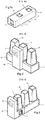
- the figure 1 shows a central module 10 which is intended for a switch device of modular design.
- This central module 10 comprises a central base 11 which is surmounted by a front face 18.
- the front face 18 comprises in particular various control / command members 19 which, for example, allow an operator to control and monitor the switching device.
- the central base 11 is intended to carry a first switch module, called the central switch module 15 (see figures 2 and 3 ).
- the central base 11 also comprises a central actuation mechanism which is intended to actuate the central switch module 15 of the switch device, that is to say to move the movable contact of the central switch module 15 from the closed position to the open position.
- the central base 11 comprises for this a central window 12 so that the actuating mechanism can access and mechanically control the movable contact of the central switch module 15 using conventional mechanical means, such as rods, connecting rods, pivots and / or gears not shown in the figures, but an example of which is described in particular in the document EP1968088 .
- the central module 10 may also include a control unit which, in conjunction in particular with the control / command members 19 of the front face 18 and / or with the remote control / command members, is responsible for controlling the mechanism. central actuation and monitor the operation of the switch device.
- the central base 11 comprises rear fixing means which are placed at the rear of the central base 11 and which are advantageously capable of removably fixing a rear base 41 to the central module 10, as well as lateral fixing means placed from each side of the central base 11 and which are capable of removably fixing two side bases 21, 31 to the central module.
- These fixing means are not detailed in this document and may include screws and nuts in particular. So that the actuating mechanism can access the side bases 21, 31 and the rear base 41 in order to control the movable contacts, the rear fixing means comprise a rear hatch 14 placed at the rear of the central base 11 and the means side fasteners include two side hatches 13 placed on each side of the central base 11.
- the same central module 10 can advantageously be used regardless of the architecture of the switching device, that is to say also in a front architecture shown in figure 2 , than in a longitudinal architecture represented in figure 3 .
- the actuating mechanism of this central module 10 is capable of controlling the movable contacts of all of the switch modules of the apparatus.
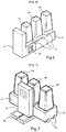
- the figure 2 shows a switch device with a front architecture. It comprises two side bases 21, 31 which are fixed laterally on each side of the central base 11 of the central module 10.
- the central base 11 carries a central switch module 15 and each side base 21, 31 carries a side switch module 25, 35.
- the central switch module 15 and the side switch modules 25, 35 are identical and can be actuated by the actuating mechanism of the central module.
- the two side hatches 13 present on each side of the central base 11 are placed opposite a corresponding hatch 23 (see figures 4a, 4b ) on each side plinth.
- Each side base 21, 31 also has a window 22 (see figures 4a, 4b ) so that the actuating mechanism can access the side switch module 25, 35.
- the side modules 21 and 31 are symmetrical with respect to a longitudinal vertical plane of the device.
- the figure 3 shows a switch device having a longitudinal architecture. It comprises a rear base 41 which is fixed to the rear of the central base 11.
- the central base 11 carries a central switch module 15 and the rear base 41 carries two rear switch modules 45, 55.
- the central switch module 15 and the modules rear switches 45, 55 are identical and can be actuated by the actuating mechanism of the central module.
- the rear hatch 14 present at the rear of the central base 11 is placed opposite a corresponding hatch 44 (see figures 5a , 5b ) on the rear base 41.
- the rear base 41 also has two windows 42, 52 (see figures 5a , 5b ) to access the two rear switch modules 45, 55.
- the hatches 13, 14, 23, 44 of the central base and the side / rear bases and then the windows 12, 22, 42, 52 have sufficient openings to transmit the movements of the central actuating mechanism to the side bases / rear, then to the moving contacts of the various switch modules.
- No electrical connection is necessary between the central base 11 and the side / rear bases 21, 31, 41, which makes the solution very simple to implement.
- the central base 11 should just include means for transmitting the movements of the actuating mechanism to the rear base 41 and the side bases 21, 31, when a rear base 41 or two side bases 21, 31 are fixed to the central module 10, in order to be able to actuate the other switch modules 25, 35, 45 of the switch device using conventional mechanical members such as for example rods, connecting rods, pivots and / or gears.
- the switch modules of the switch device are removably fixed on their respective base.
- the central switch module 15 is removably fixed on the central base 11 of the central module 10
- the rear switch modules 45, 55 are removably fixed on the rear base 41
- the side switch modules 25, 35 are fixedly fixed. removable manner on their respective lateral base 21, 31, which in particular makes it possible to easily replace a switch module.
- the invention provides several types of side bases and rear base which can be used with the same invariant central base 10, so as to be able to construct switch devices of different ratings (that is to say working at different nominal currents) for example from 630A to 3150A.
- the switching device will have a different distance between phases. Thanks to this, the same central base 10 can be used as a base for the construction of several calibers of switching devices, for example a rear base of type 41 for calibers 630A and 1250A, or a rear base of type 41 'for caliber. up to 3150A, associated with switch modules 15, 45, 55 of different ratings.
- the distances d1, d2 and d1 ', d2' are of course arranged so that the distances between phases of a device are identical, that is to say that the distances between on the one hand the switch modules 45 and 55 and on the other hand, the switch modules 45 and 15 are identical.
- FIG. 1 This characteristic is also found in the case of a front architecture with the possibility of adding different sizes of side modules 21, 31 to the central module 10.
- figures 4a, 4b thus show side modules 21, respectively 21 ', which differ in the distance between their window 22 and the rim on the side having the hatch 23. This makes it possible to have a greater distance between phases in the case of side modules 21'. Thanks to this, the same central base 10 can be used as a base for the construction of several ratings of switching devices, for example type 21 side bases for the 630A and 1250A ratings, and type 21 'side bases for the ratings. up to 3150A, associated with switch modules 15, 25, 35 of different ratings.
- the invention also provides for being able to easily add a booster 17 between each base and its associated switch module.
- Overcoming a switch module with respect to its base advantageously makes it possible to withstand higher nominal voltages, while not increasing the dielectric stresses.
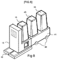
- the figure 6 thus shows the device switch figure 3 in which a booster 17 has been added for each switch module 15, 35, 45.
- a similar booster could have been added in the example of figure 2 .
- Such a booster may for example have a height of approximately 80 to 100 mm with an elastomer part to ensure the sealing of the poles. It is used for example to be able to go from a nominal voltage of 17.5kV to 24kV.
- these two characteristics can be used independently of one another, namely to use a booster to support a higher nominal voltage and / or to use side / rear bases with greater distances between phases to support a greater nominal current.
- a central module is in fact intended to be placed on a mobile truck so as to be able to approach and then electrically connect the switching device inside a high voltage cell.
- the movable carriage is movable in translation in order to be able to approach the switching device and further comprises a conventional drive means, for example an endless screw which can be motorized or actuated by a crank for connecting the switching device.
- a mobile trolley comprises a plate on which the switching device is fixed and the dimensions of which are therefore adapted to this switching device.
- the plate comprises for example wheels to be able to move the trolley easily.
- the modular architecture of the invention it is more difficult to plan and adapt the dimensions of such a plate given the different dimensions of the switch device according to the architecture chosen during the mounting.
- a mobile carriage 16 is directly fixed under the central module 10 of the switching device, but given that either two side bases 21, 31, or a rear base 41, are assembled to the central base 11 of the central module, it is appropriate ensure the stability and correct movement of the switch device.
- the invention provides, within the framework of the longitudinal architecture of the figure 8 , to be able to add two casters 46 which are placed on each of the lateral sides of the rear base 41.
- the invention provides for being able to add two casters 26 which are placed on the outer side of the lateral base 21 (that is to say on the lateral side not fixed to the central base 11) and two castors on the outer side of the base lateral 31 (not shown).
- two casters 26 which are placed on the outer side of the lateral base 21 (that is to say on the lateral side not fixed to the central base 11) and two castors on the outer side of the base lateral 31 (not shown).
- there are four casters which facilitate the movement of the carriage 16 and of the switching device and ensure the stability of the assembly. They can for example be guided in rails present in the high voltage cell.
- These different castors are easily mounted on the bases when mounting the switch device.
Landscapes
- Engineering & Computer Science (AREA)
- Manufacturing & Machinery (AREA)
- Switch Cases, Indication, And Locking (AREA)
- Gas-Insulated Switchgears (AREA)
Abstract
Description
- La présente invention concerne un appareil électrique interrupteur triphasé présentant une architecture modulaire, en particulier un appareil interrupteur opérant sous moyenne ou haute tension, c'est-à-dire opérant à une tension supérieure à 1000V. L'invention concerne également un module central d'un tel appareil interrupteur.
- Dans le présent document, le terme «appareil interrupteur» regroupe indifféremment plusieurs types d'appareils électriques comme un interrupteur, un disjoncteur, un contacteur, un interrupteur fusible, un recloser, un sectionneur, etc.
- Les appareils interrupteurs triphasés existent généralement soit avec une architecture dite frontale dans laquelle les trois pôles de l'appareil sont placés les uns à côté des autres selon une direction sensiblement parallèle à la face avant de l'appareil interrupteur, soit avec une architecture dite longitudinale dans laquelle les trois pôles de l'appareil sont placés les uns derrière les autres dans une direction sensiblement perpendiculaire à la face avant de l'appareil interrupteur.
- Une architecture frontale est par exemple bien adaptée aux contraintes des appareils destinés à être placés dans des cellules haute tension dites primaires, alors qu'une architecture longitudinale est par exemple bien adaptée aux contraintes des appareils placés dans des cellules haute tension dites secondaires dont les dimensions sont souvent plus réduites.
- D'autre part, il est connu que les distances à respecter entre chaque phase d'un appareil interrupteur peuvent être différentes en fonction de la tension nominale et du courant nominal d'utilisation de l'appareil, pour des raisons évidentes de contraintes diélectriques liées à la tension et des contraintes d'échauffement dues au courant.
- Le document
EP2437277 décrit un agencement pour un disjoncteur haute tension multiphases en architecture frontale et dont les pôles sont montés de telle sorte que la distance entre pôles peut être facilement réglée, par exemple grâce à différents types d'organes de raccordement intermédiaires entre les pôles. - Un des buts de l'invention est de pouvoir rationaliser la fabrication et la gestion industrielle des appareils interrupteurs, c'est-à-dire d'être capable de fabriquer très facilement des appareils selon l'une ou l'autre des architectures et selon différents calibres et tensions en utilisant le minimum de pièces différentes, de façon à diminuer les coûts et à simplifier le processus de fabrication.
- Pour cela, l'appareil interrupteur selon l'invention est conçu selon une structure modulaire en utilisant au maximum des modules standardisés en fonction de l'utilisation prévue par les clients, ce qui permet donc de réaliser, le plus tard possible dans la chaîne de fabrication et de montage de l'appareil, une personnalisation de l'architecture et le choix du courant et de la tension de l'appareil interrupteur.
- L'invention décrit un module central pour un appareil interrupteur électrique triphasé, le module central comportant un socle central destiné à porter un module interrupteur central et une face avant comprenant des organes de contrôle/commande pour l'appareil interrupteur. Le socle central comporte :
- des moyens de fixation arrière placés à l'arrière du socle central et aptes à fixer, de manière amovible au module central, un socle arrière destiné à porter deux modules interrupteurs arrières,
- des moyens de fixation latéraux placés de chaque côté du socle central et aptes à fixer de manière amovible au module central deux socles latéraux destinés à porter chacun un module interrupteur latéral,
- un mécanisme d'actionnement destiné à actionner le module interrupteur central de l'appareil interrupteur,
- des moyens de transmission des mouvements du mécanisme d'actionnement vers un socle arrière et des socles latéraux lorsque ceux-ci sont fixés au module central, pour pouvoir actionner d'autres modules interrupteurs de l'appareil interrupteur.
- Selon une caractéristique, pour faire passer les moyens de transmission des mouvements du mécanisme d'actionnement vers d'autres modules interrupteurs, les moyens de fixation arrière comprennent une trappe arrière placée à l'arrière du socle central et les moyens de fixation latéraux comprennent deux trappes latérales placées de chaque côté du socle central.
- L'invention décrit également un premier type d'appareil interrupteur électrique triphasé comprenant un module central avec un module interrupteur central porté par le socle central, et comprenant deux socles latéraux fixés latéralement de chaque côté du socle central, chaque socle latéral portant un module interrupteur latéral, le module interrupteur central et les modules interrupteurs latéraux étant actionnables par le mécanisme d'actionnement du module central.
- Selon une caractéristique, le module interrupteur central et les modules interrupteurs latéraux sont agencés pour que l'appareil interrupteur ait des distances entre phases identiques. Selon une autre caractéristique, le module interrupteur central et les deux modules interrupteurs latéraux sont identiques. Selon une autre caractéristique, le module interrupteur central et les modules interrupteurs latéraux sont chacun surmonté d'un rehausseur identique. Selon une autre caractéristique, les deux socles latéraux comportent chacun deux roulettes placées sur un côté extérieur.
- L'invention décrit également un deuxième type d'appareil interrupteur électrique triphasé comprenant un module central avec un module interrupteur central porté par le socle central, et comprenant un socle arrière fixé à l'arrière du socle central, le socle arrière portant deux modules interrupteurs arrières, le module interrupteur central et les modules interrupteurs arrières étant actionnables par le mécanisme d'actionnement du module central.
- Selon une caractéristique, le module interrupteur central et les modules interrupteurs arrières sont agencés pour que l'appareil interrupteur ait des distances entre phases identiques. Selon une autre caractéristique, le module interrupteur central et les deux modules interrupteurs arrières sont identiques. Selon une autre caractéristique, le module interrupteur central et les modules interrupteurs arrières sont chacun surmonté d'un rehausseur identique. Selon une autre caractéristique, le socle arrière comporte deux roulettes placées sur chacun des côtés latéraux du socle arrière.
- D'autres caractéristiques vont apparaître dans la description détaillée qui suit faite en regard des dessins annexés dans lesquels :
- [
FIG. 1 ] lafigure 1 montre un module central pour appareil interrupteur conforme à l'invention, - [
FIG. 2 ] lafigure 2 représente un appareil interrupteur ayant une architecture frontale et utilisant un module central selon lafigure 1 , - [
FIG. 3 ] lafigure 3 représente un appareil interrupteur ayant une architecture longitudinale et utilisant un module central selon lafigure 1 , - [
FIG. 4a ] - [
FIG. 4b ] lesfigures 4a et 4b détaillent deux exemples d'un socle latéral raccordable au module central pour des calibres différents - [
FIG. 5a ] - [
FIG. 5b ] lesfigures 5a et5b détaillent deux exemples d'un socle arrière raccordable au module central pour des calibres différents, - [
FIG. 6 ] lafigure 6 reprend l'appareil interrupteur de lafigure 3 avec des rehausseurs pour les modules interrupteurs, - [
FIG. 7 ] - [
FIG. 8 ] lesfigures 7 et8 reprennent lesfigures 2 et 3 dans une version débrochable. - Un appareil interrupteur électrique de construction modulaire dispose d'un module interrupteur pour chaque phase d'un réseau d'alimentation électrique. Dans le cas d'un appareil triphasé, il y a donc trois modules interrupteurs. De façon classique, chaque module interrupteur est capable de couper une phase du réseau d'alimentation électrique grâce à un (ou éventuellement plusieurs) contact mobile qui coopère avec un (ou plusieurs) contact fixe. En position dite ouverte le contact mobile est séparé du contact fixe, et en position dite fermée le contact mobile est connecté au contact fixe. L'actionnement des contacts mobiles des différents modules interrupteurs d'un appareil interrupteur doit être effectué de façon mécaniquement synchronisée pour assurer par exemple la commutation simultanée de toutes les phases du réseau d'alimentation électrique, à l'ouverture comme à la fermeture.
- La
figure 1 montre un module central 10 qui est destiné à un appareil interrupteur de conception modulaire. Ce module central 10 comporte un socle central 11 de base qui est surmonté par une face avant 18. La face avant 18 comprend notamment divers organes de contrôle/commande 19 qui permettent par exemple à un opérateur de piloter et surveiller l'appareil interrupteur. Le socle central 11 est destiné à porter un premier module interrupteur, appelé module interrupteur central 15 (voirfigures 2 et 3 ). - Le socle central 11 comporte également un mécanisme d'actionnement central qui est destiné à actionner le module interrupteur central 15 de l'appareil interrupteur, c'est-à-dire à déplacer le contact mobile du module interrupteur central 15 de la position fermée à la position ouverte. Le socle central 11 comporte pour cela une fenêtre centrale 12 de sorte que le mécanisme d'actionnement puisse accéder et commander mécaniquement le contact mobile du module interrupteur central 15 à l'aide de moyens mécaniques classiques, tels que tringles, bielles, pivots et/ou engrenages non représentés sur les figures, mais dont un exemple est décrit notamment dans le document
EP1968088 . - Le module central 10 peut également comporter une unité de commande qui, en liaison notamment avec les organes de contrôle/commande 19 de la face avant 18 et/ou avec des organes de contrôle/commande à distance, est en charge de piloter le mécanisme d'actionnement central et de surveiller le fonctionnement de l'appareil interrupteur.
- En référence aux
figures 2 et 3 , le socle central 11 comporte des moyens de fixation arrière qui sont placés à l'arrière du socle central 11 et qui sont avantageusement aptes à fixer de manière amovible un socle arrière 41 au module central 10, ainsi que des moyens de fixation latéraux placés de chaque côté du socle central 11 et qui sont aptes à fixer de manière amovible deux socles latéraux 21, 31 au module central. Ces moyens de fixation ne sont pas détaillés dans le présent document et peuvent comprendre notamment des vis et écrous. Pour que le mécanisme d'actionnement puisse accéder aux socles latéraux 21, 31 et au socle arrière 41 en vue de commander les contacts mobiles, les moyens de fixation arrière comprennent une trappe arrière 14 placée à l'arrière du socle central 11 et les moyens de fixation latéraux comprennent deux trappes latérales 13 placées de chaque côté du socle central 11. - Grâce à l'invention, un même module central 10 est avantageusement utilisable quelle que soit l'architecture de l'appareil interrupteur, c'est-à-dire aussi bien dans une architecture frontale représentée en
figure 2 , que dans une architecture longitudinale représentée enfigure 3 . De plus, le mécanisme d'actionnement de ce module central 10 est capable de commander les contacts mobiles de l'ensemble des modules interrupteurs de l'appareil. - Ainsi, la
figure 2 montre un appareil interrupteur ayant une architecture frontale. Il comporte deux socles latéraux 21, 31 qui sont fixés latéralement de chaque côté du socle central 11 du module central 10. Le socle central 11 porte un module interrupteur central 15 et chaque socle latéral 21, 31 porte un module interrupteur latéral 25, 35. Le module interrupteur central 15 et les modules interrupteurs latéraux 25, 35 sont identiques et actionnables par le mécanisme d'actionnement du module central. Les deux trappes latérales 13 présentes de chaque côté du socle central 11 sont placées en vis-à-vis d'une trappe correspondante 23 (voirfigures 4a, 4b ) sur chaque socle latéral. Chaque socle latéral 21, 31 comporte également une fenêtre 22 (voirfigures 4a, 4b ) pour que le mécanisme d'actionnement puisse accéder au module interrupteur latéral 25, 35. Les modules latéraux 21 et 31 sont symétriques par rapport à un plan vertical longitudinal de l'appareil. - De même, la
figure 3 montre un appareil interrupteur ayant une architecture longitudinale. Il comporte un socle arrière 41 qui est fixé à l'arrière du socle central 11. Le socle central 11 porte un module interrupteur central 15 et le socle arrière 41 porte deux modules interrupteurs arrières 45, 55. Le module interrupteur central 15 et les modules interrupteurs arrières 45, 55 sont identiques et actionnables par le mécanisme d'actionnement du module central. La trappe arrière 14 présente à l'arrière du socle central 11 est placée en vis-à-vis d'une trappe correspondante 44 (voirfigures 5a ,5b ) sur le socle arrière 41. Le socle arrière 41 comporte également deux fenêtres 42, 52 (voirfigures 5a ,5b ) pour accéder aux deux modules interrupteurs arrières 45, 55. - En résumé, les trappes 13, 14, 23, 44 du socle central et des socles latéraux/arrière puis les fenêtres 12, 22, 42, 52 présentent des ouvertures suffisantes pour transmettre les mouvements du mécanisme d'actionnement central vers les socles latéraux/arrière, puis vers les contacts mobiles des différents modules interrupteurs. Aucune liaison électrique n'est nécessaire entre le socle central 11 et les socles latéraux/arrière 21, 31, 41, ce qui rend la solution très simple à mettre en œuvre. Le socle central 11 doit juste comporter des moyens de transmission des mouvements du mécanisme d'actionnement vers le socle arrière 41 et les socles latéraux 21, 31, lorsque un socle arrière 41 ou deux socles latéraux 21, 31 sont fixés au module central 10, pour pouvoir actionner les autres modules interrupteurs 25, 35, 45, de l'appareil interrupteur à l'aide d'organes mécaniques classiques tels que par exemple tringles, bielles, pivots et/ou engrenages.
- Par ailleurs, tous les modules interrupteurs de l'appareil interrupteur sont fixés de manière amovible sur leur socle respectif. Ainsi, le module interrupteur central 15 est fixé de manière amovible sur le socle central 11 du module central 10, les modules interrupteurs arrières 45, 55 sont fixés de manière amovible sur le socle arrière 41 et les modules interrupteurs latéraux 25, 35 sont fixés de manière amovible sur leur socle latéral 21, 31 respectif, ce qui notamment permet de remplacer facilement un module interrupteur.
- Dans l'architecture de la
figure 3 , on note que les trappes latérales 13 de chaque côté du socle central 11 sont présentes mais ne sont pas utilisées car il n'y a pas de socle latéral 21, 31 fixé au socle central 11. De même, dans l'architecture de lafigure 2 , la trappe arrière 14 du socle central 11 est présente mais n'est pas utilisée car il n'y a pas de socle arrière 41 fixé au socle central 11. Pour les masquer, un cache étanche peut alors bien sûr être placé sur les différentes trappes non utilisées. - Selon un mode de réalisation préféré, l'invention prévoit plusieurs types de socles latéraux et socle arrière qui sont utilisables avec un même socle central 10 invariant, de façon à pouvoir construire des appareils interrupteurs de calibres différents (c'est-à-dire travaillant à des intensités nominales différentes) par exemple de 630A à 3150A.
- On voit ainsi sur les
figures 5a , respectivement 5b, que les deux socles arrière 41, respectivement 41', présentent des distances différentes d1, respectivement d1', entre les axes des deux fenêtres 42, 52. De même, les socles arrière 41, respectivement 41', présentent des distances différentes d2, respectivement d2', entre l'axe de leur première fenêtre 42 et le rebord du côté ayant la trappe 44. - Donc, suivant qu'un module central 10 est utilisé avec un socle arrière 41 ou un socle arrière 41', l'appareil interrupteur aura une distance entre phases différente. Grâce à cela, un même socle central 10 peut servir de base à la construction de plusieurs calibres d'appareils interrupteurs, par exemple un socle arrière de type 41 pour les calibres 630A et 1250A, ou un socle arrière de type 41' pour le calibre allant jusqu'à 3150A, associés à des modules interrupteurs 15, 45, 55 de calibres différents.
- Les distances d1, d2 et d1', d2' sont bien sûr agencées pour que les distances entre phases d'un appareil soient identiques, c'est-à-dire que les distances entre d'une part les modules interrupteurs 45 et 55 et d'autre part les modules interrupteurs 45 et 15 soient identiques.
- Cette caractéristique se retrouve également dans le cas d'une architecture frontale avec la possibilité d'adjoindre différentes tailles de modules latéraux 21, 31 au module central 10. Les
figures 4a, 4b montrent ainsi des modules latéraux 21, respectivement 21', qui diffèrent par la distance entre leur fenêtre 22 et le rebord du côté ayant la trappe 23. Ceci permet d'avoir une distance entre phases plus importante dans le cas des modules latéraux 21'. Grâce à cela, un même socle central 10 peut servir de base à la construction de plusieurs calibres d'appareils interrupteurs, par exemple des socles latéraux de type 21 pour les calibres 630A et 1250A, et des socles latéraux de type 21' pour les calibres jusqu'à 3150A, associés à des modules interrupteurs 15, 25, 35 de calibres différents. - Selon une autre caractéristique préférée, l'invention prévoit également de pouvoir facilement ajouter un rehausseur 17 entre chaque socle et son module interrupteur associé. Le fait de surmonter un module interrupteur par rapport à son socle permet avantageusement de supporter des tensions nominales plus importantes, tout en n'augmentant pas les contraintes diélectriques. La
figure 6 montre ainsi l'appareil interrupteur de lafigure 3 dans lequel un rehausseur 17 a été ajouté pour chaque module interrupteur 15, 35, 45. Bien sûr, un rehausseur similaire aurait pu être ajouté dans l'exemple de lafigure 2 . - Un tel rehausseur peut par exemple avoir une hauteur d'environ 80 à 100 mm avec une partie en élastomère pour assurer l'étanchéité des pôles. Il est utilisé par exemple pour pouvoir passer d'une tension nominale de 17,5kV à 24kV.
- Avantageusement, ces deux caractéristiques peuvent être utilisées indépendamment l'une de l'autre, à savoir utiliser un rehausseur pour supporter une tension nominale plus importante et/ou utiliser des socles latéraux/arrière avec des distances entre phases plus importantes pour supporter une plus forte intensité nominale.
- Les
figures 7 et8 montrent une version débrochable de l'invention dans l'une et l'autre des architectures présentées. Un module central est en effet destiné à être placé sur un chariot mobile (truck en anglais) de façon à pouvoir approcher puis raccorder électriquement l'appareil interrupteur à l'intérieur d'une cellule haute tension. Le chariot mobile est mobile en translation pour pouvoir approcher l'appareil interrupteur et comporte en plus un moyen d'entrainement classique, par exemple une vis sans fin qui est motorisable ou actionnable par manivelle pour le raccordement de l'appareil interrupteur. D'habitude, un chariot mobile comporte un plateau sur lequel l'appareil interrupteur est fixé et dont les dimensions sont donc adaptées à cet appareil interrupteur. Le plateau comporte par exemple des roues pour pouvoir déplacer le chariot facilement. - Or, dans le cas de l'architecture modulaire de l'invention, il est plus difficile de prévoir et d'adapter les dimensions d'un tel plateau vu les différents encombrements de l'appareil interrupteur en fonction de l'architecture choisie lors du montage. C'est pourquoi un chariot mobile 16 est directement fixé sous le module central 10 de l'appareil interrupteur mais vu que soit deux socles latéraux 21, 31, soit un socle arrière 41, sont assemblés au socle central 11 du module central, il convient d'assurer la stabilité et le bon déplacement de l'appareil interrupteur. Pour cela, l'invention prévoit, dans le cadre de l'architecture longitudinale de la
figure 8 , de pouvoir ajouter deux roulettes 46 qui sont placées sur chacun des côtés latéraux du socle arrière 41. De même, dans le cadre de l'architecture frontale de lafigure 7 , l'invention prévoit de pouvoir ajouter deux roulettes 26 qui sont placées sur le côté extérieur du socle latéral 21 (c'est-à-dire sur le côté latéral non fixé au socle central 11) et deux roulettes sur le côté extérieur du socle latéral 31 (non représentées). Ainsi, dans les deux architectures, il y a quatre roulettes qui facilitent le déplacement du chariot 16 et de l'appareil interrupteur et assurent la stabilité de l'ensemble. Elles peuvent par exemple être guidées dans des rails présents dans la cellule haute tension. Ces différentes roulettes sont facilement montées sur les socles lors du montage de l'appareil interrupteur.
Claims (12)
- Module central pour un appareil interrupteur électrique triphasé, le module central (10) comportant un socle central (11) destiné à porter un module interrupteur central (15) et une face avant comprenant des organes de contrôle/commande (19) pour l'appareil interrupteur, caractérisé en ce que le socle central (11) comporte :- des moyens de fixation arrière placés à l'arrière du socle central (11) et aptes à fixer, de manière amovible au module central (10), un socle arrière (41) destiné à porter deux modules interrupteurs arrières (45, 55),- des moyens de fixation latéraux placés de chaque côté du socle central (11) et aptes à fixer de manière amovible au module central (10) deux socles latéraux (21, 31) destinés à porter chacun un module interrupteur latéral (25, 35),- un mécanisme d'actionnement destiné à actionner le module interrupteur central (15) de l'appareil interrupteur,- des moyens de transmission des mouvements du mécanisme d'actionnement vers un socle arrière (41) et des socles latéraux (21, 31) lorsque ceux-ci sont fixés au module central (10), pour pouvoir actionner d'autres modules interrupteurs (25, 35, 45) de l'appareil interrupteur.
- Module central selon la revendication 1, caractérisé en ce que, pour faire passer les moyens de transmission des mouvements du mécanisme d'actionnement vers d'autres modules interrupteurs (25, 35, 45), les moyens de fixation arrière comprennent une trappe arrière (14) placée à l'arrière du socle central (11) et les moyens de fixation latéraux comprennent deux trappes latérales (13) placées de chaque côté du socle central (11).
- Appareil interrupteur électrique triphasé comprenant un module central (10) selon la revendication 1 ou 2, avec un module interrupteur central (15) porté par le socle central (11), et comprenant deux socles latéraux (21, 31) fixés latéralement de chaque côté du socle central (11), chaque socle latéral portant un module interrupteur latéral (25, 35), le module interrupteur central (15) et les modules interrupteurs latéraux (25, 35) étant actionnables par le mécanisme d'actionnement du module central.
- Appareil interrupteur selon la revendication 3, caractérisé en ce que le module interrupteur central (15) et les modules interrupteurs latéraux (25, 35) sont agencés pour que l'appareil interrupteur ait des distances entre phases identiques.
- Appareil interrupteur selon la revendication 3, caractérisé en ce que le module interrupteur central (15) et les deux modules interrupteurs latéraux (25, 35) sont identiques.
- Appareil interrupteur selon la revendication 3, caractérisé en ce que le module interrupteur central (15) et les modules interrupteurs latéraux (25, 35) sont chacun surmonté d'un rehausseur (17) identique.
- Appareil interrupteur selon la revendication 3, caractérisé en ce que les deux socles latéraux (21, 31) comportent chacun deux roulettes (26) placées sur un côté extérieur.
- Appareil interrupteur électrique triphasé, comprenant un module central (10) selon la revendication 1 ou 2, avec un module interrupteur central (15) porté par le socle central (11), et comprenant un socle arrière (41) fixé à l'arrière du socle central (11), le socle arrière portant deux modules interrupteurs arrières (35, 45), le module interrupteur central (15) et les modules interrupteurs arrières (35, 45) étant actionnables par le mécanisme d'actionnement du module central.
- Appareil interrupteur selon la revendication 8, caractérisé en ce que le module interrupteur central (15) et les modules interrupteurs arrières (35, 45) sont agencés pour que l'appareil interrupteur ait des distances entre phases identiques.
- Appareil interrupteur selon la revendication 8, caractérisé en ce que le module interrupteur central (15) et les deux modules interrupteurs arrières (35, 45) sont identiques.
- Appareil interrupteur selon la revendication 8, caractérisé en ce que le module interrupteur central (15) et les modules interrupteurs arrières (35, 45) sont chacun surmonté d'un rehausseur (17) identique.
- Appareil interrupteur selon la revendication 8, caractérisé en ce que le socle arrière (41) comporte deux roulettes (46) placées sur chacun des côtés latéraux du socle arrière.
Applications Claiming Priority (1)
| Application Number | Priority Date | Filing Date | Title |
|---|---|---|---|
| FR1908092A FR3098976B1 (fr) | 2019-07-17 | 2019-07-17 | Architecture d'un appareil électrique interrupteur |
Publications (2)
| Publication Number | Publication Date |
|---|---|
| EP3767657A1 true EP3767657A1 (fr) | 2021-01-20 |
| EP3767657B1 EP3767657B1 (fr) | 2021-07-07 |
Family
ID=68581944
Family Applications (1)
| Application Number | Title | Priority Date | Filing Date |
|---|---|---|---|
| EP20179615.8A Active EP3767657B1 (fr) | 2019-07-17 | 2020-06-12 | Architecture d'un appareil électrique interrupteur |
Country Status (5)
| Country | Link |
|---|---|
| US (1) | US11211207B2 (fr) |
| EP (1) | EP3767657B1 (fr) |
| KR (1) | KR102842315B1 (fr) |
| CN (1) | CN112242260B (fr) |
| FR (1) | FR3098976B1 (fr) |
Citations (4)
| Publication number | Priority date | Publication date | Assignee | Title |
|---|---|---|---|---|
| US6198062B1 (en) * | 1999-05-17 | 2001-03-06 | Joslyn Hi-Voltage Corporation | Modular, high-voltage, three phase recloser assembly |
| EP1496535A1 (fr) * | 2002-04-12 | 2005-01-12 | Mitsubishi Denki Kabushiki Kaisha | Tube electronique |
| EP1968088A2 (fr) | 2000-03-31 | 2008-09-10 | Schneider Electric Industries SAS | Appareillage électrique de coupure multipolaire muni d'un mecanisme d'entrainement et de modules de coupure |
| EP2437277A1 (fr) | 2010-09-29 | 2012-04-04 | ABB Technology AG | Agencement de disjoncteur de moyenne tension |
Family Cites Families (12)
| Publication number | Priority date | Publication date | Assignee | Title |
|---|---|---|---|---|
| US3582589A (en) * | 1968-01-30 | 1971-06-01 | Westinghouse Electric Corp | Fluid-blast circuit interrupter with piston assembly and electromagnetic driving means |
| DE58905809D1 (de) * | 1988-06-14 | 1993-11-11 | Sprecher En Ag Oberentfelden | Vakuumschalteranordnung. |
| US5609245A (en) * | 1994-12-20 | 1997-03-11 | Square D Company | Modular switch interior assembly and method of assembling same |
| KR100390795B1 (ko) * | 2000-12-04 | 2003-07-10 | 엘지산전 주식회사 | 진공 차단기 |
| CN101681744A (zh) * | 2007-04-28 | 2010-03-24 | Abb股份有限公司 | 室内布线开关设备 |
| EP2325858A1 (fr) * | 2009-11-20 | 2011-05-25 | ABB Technology AG | Agencement de disjoncteur de moyenne tension |
| KR101100707B1 (ko) * | 2009-12-31 | 2012-01-02 | 엘에스산전 주식회사 | 진공차단기 |
| US9019050B2 (en) * | 2011-12-06 | 2015-04-28 | Schneider Electric Industries Sas | Electric switching system comprising an electric switching module including two elements coupling a contact(S)-holder with its driving device |
| DE202012013384U1 (de) * | 2012-10-22 | 2016-08-25 | Abb Ag | Rotatorisch betätigte Schaltanordnung für eine Schaltanlage |
| GB2521135B (en) * | 2013-12-10 | 2017-01-18 | Tavrida Electric Holding Ag | Switching apparatus for electrical power systems |
| US20150332883A1 (en) * | 2014-05-14 | 2015-11-19 | Eaton Corporation | Electrical switching apparatus and linear actuator assembly therefor |
| FR3042640B1 (fr) * | 2015-10-20 | 2019-05-31 | Schneider Electric Industries Sas | Appareil de commutation electrique comportant un mecanisme de commutation et au moins un module auxiliaire |
-
2019
- 2019-07-17 FR FR1908092A patent/FR3098976B1/fr not_active Expired - Fee Related
-
2020
- 2020-06-12 EP EP20179615.8A patent/EP3767657B1/fr active Active
- 2020-07-07 US US16/922,164 patent/US11211207B2/en active Active
- 2020-07-10 KR KR1020200085499A patent/KR102842315B1/ko active Active
- 2020-07-16 CN CN202010684284.6A patent/CN112242260B/zh active Active
Patent Citations (4)
| Publication number | Priority date | Publication date | Assignee | Title |
|---|---|---|---|---|
| US6198062B1 (en) * | 1999-05-17 | 2001-03-06 | Joslyn Hi-Voltage Corporation | Modular, high-voltage, three phase recloser assembly |
| EP1968088A2 (fr) | 2000-03-31 | 2008-09-10 | Schneider Electric Industries SAS | Appareillage électrique de coupure multipolaire muni d'un mecanisme d'entrainement et de modules de coupure |
| EP1496535A1 (fr) * | 2002-04-12 | 2005-01-12 | Mitsubishi Denki Kabushiki Kaisha | Tube electronique |
| EP2437277A1 (fr) | 2010-09-29 | 2012-04-04 | ABB Technology AG | Agencement de disjoncteur de moyenne tension |
Also Published As
| Publication number | Publication date |
|---|---|
| EP3767657B1 (fr) | 2021-07-07 |
| FR3098976A1 (fr) | 2021-01-22 |
| US11211207B2 (en) | 2021-12-28 |
| US20210020387A1 (en) | 2021-01-21 |
| CN112242260B (zh) | 2025-03-14 |
| KR102842315B1 (ko) | 2025-08-04 |
| KR20210010359A (ko) | 2021-01-27 |
| FR3098976B1 (fr) | 2021-06-11 |
| CN112242260A (zh) | 2021-01-19 |
Similar Documents
| Publication | Publication Date | Title |
|---|---|---|
| EP0320412B1 (fr) | Disjoncteur multipolaire de calibre élevé constitué par deux boîtiers moulés accolés | |
| EP2575155B1 (fr) | Appareillage de distribution électrique moyenne tension | |
| WO2010043604A1 (fr) | Appareil de commutation electrique muni de deux interrupteurs, tels qu'un sectionneur de barre et un sectionneur de terre et comprenant des moyens d'entrainement communs aux contacts mobiles des interrupteurs | |
| EP0693763B1 (fr) | Interrupteurs électriques moyenne tension | |
| EP3767657B1 (fr) | Architecture d'un appareil électrique interrupteur | |
| EP2771896B1 (fr) | Dispositif d'aiguillage electrique a un point de jonction entre deux parties d'un reseau | |
| FR3072826B1 (fr) | Appareil de coupure electrique, procede et installation utilisant un tel appareil | |
| FR2896335A1 (fr) | Disjoncteur de generateur avec resistance inseree | |
| FR2513006A1 (fr) | Dispositif interrupteur modulaire a poles multiples | |
| EP4343808B1 (fr) | Dispositif non-électrique pour la substitution d'un capteur de courant dans une chambre de coupure d'un interrupteur-sectionneur, ainsi qu interrupteur-sectionneur comportant un tel dispositif non-électrique | |
| EP0731481A1 (fr) | Disjoncteur auto-sectionneur à sectionnement auto-verrouillé en position fermée des chambres de coupure | |
| EP0204594A1 (fr) | Appareil interrupteur protégé contre les courants de court-circuit | |
| EP3159906A1 (fr) | Appareil de commutation électrique comportant un mécanisme de commutation et au moins un module auxiliaire | |
| EP2575154B1 (fr) | Cellule de distribution électrique moyenne tension | |
| EP0009287A1 (fr) | Appareil électrique comprenant une série de prises de tension et un équipage sélecteur et/ou un ensemble rupteur | |
| EP2945176B1 (fr) | Appareillage de coupure électrique moyenne tension utilisant la technique de coupure dans le vide | |
| FR2849968A1 (fr) | Centre de transformation pour transformateur autoprotege | |
| EP2743957B1 (fr) | Appareil de coupure de courant électrique, en particulier un disjoncteur de branchement | |
| EP4256662B1 (fr) | Dispositif de châssis pour appareil électrique de coupure débrochable et ensemble comprenant un tel dispositif et un tel appareil | |
| EP3496218A1 (fr) | Dispositif de raccordement d'un chariot mobile portant un appareillage electrique a une cellule moyenne ou haute tension, et cellule comportant un tel dispositif | |
| FR2798011A1 (fr) | Poste a double jeu de barres et appareil de coupure et d'aiguillage destine a etre utilise dans ce poste | |
| EP3471128B1 (fr) | Ensemble comportant un appareil electrique modulaire et un auxiliaire modulaire apte a etre associe audit appareil sur un rail de montage | |
| FR2586868A1 (fr) | Armoire de raccordement interruptible en derivation. | |
| EP2743956B1 (fr) | Appareil de coupure de courant électrique, en particulier un disjoncteur de branchement | |
| FR2960697A1 (fr) | Chassis de montage pour appareils electriques |
Legal Events
| Date | Code | Title | Description |
|---|---|---|---|
| PUAI | Public reference made under article 153(3) epc to a published international application that has entered the european phase |
Free format text: ORIGINAL CODE: 0009012 |
|
| STAA | Information on the status of an ep patent application or granted ep patent |
Free format text: STATUS: THE APPLICATION HAS BEEN PUBLISHED |
|
| AK | Designated contracting states |
Kind code of ref document: A1 Designated state(s): AL AT BE BG CH CY CZ DE DK EE ES FI FR GB GR HR HU IE IS IT LI LT LU LV MC MK MT NL NO PL PT RO RS SE SI SK SM TR |
|
| AX | Request for extension of the european patent |
Extension state: BA ME |
|
| STAA | Information on the status of an ep patent application or granted ep patent |
Free format text: STATUS: REQUEST FOR EXAMINATION WAS MADE |
|
| GRAP | Despatch of communication of intention to grant a patent |
Free format text: ORIGINAL CODE: EPIDOSNIGR1 |
|
| STAA | Information on the status of an ep patent application or granted ep patent |
Free format text: STATUS: GRANT OF PATENT IS INTENDED |
|
| 17P | Request for examination filed |
Effective date: 20210129 |
|
| RBV | Designated contracting states (corrected) |
Designated state(s): AL AT BE BG CH CY CZ DE DK EE ES FI FR GB GR HR HU IE IS IT LI LT LU LV MC MK MT NL NO PL PT RO RS SE SI SK SM TR |
|
| RIC1 | Information provided on ipc code assigned before grant |
Ipc: H01H 33/52 20060101ALI20210217BHEP Ipc: H01H 33/02 20060101AFI20210217BHEP Ipc: H01H 11/00 20060101ALI20210217BHEP |
|
| GRAS | Grant fee paid |
Free format text: ORIGINAL CODE: EPIDOSNIGR3 |
|
| INTG | Intention to grant announced |
Effective date: 20210301 |
|
| GRAJ | Information related to disapproval of communication of intention to grant by the applicant or resumption of examination proceedings by the epo deleted |
Free format text: ORIGINAL CODE: EPIDOSDIGR1 |
|
| GRAL | Information related to payment of fee for publishing/printing deleted |
Free format text: ORIGINAL CODE: EPIDOSDIGR3 |
|
| STAA | Information on the status of an ep patent application or granted ep patent |
Free format text: STATUS: REQUEST FOR EXAMINATION WAS MADE |
|
| INTC | Intention to grant announced (deleted) | ||
| GRAP | Despatch of communication of intention to grant a patent |
Free format text: ORIGINAL CODE: EPIDOSNIGR1 |
|
| STAA | Information on the status of an ep patent application or granted ep patent |
Free format text: STATUS: GRANT OF PATENT IS INTENDED |
|
| GRAA | (expected) grant |
Free format text: ORIGINAL CODE: 0009210 |
|
| STAA | Information on the status of an ep patent application or granted ep patent |
Free format text: STATUS: THE PATENT HAS BEEN GRANTED |
|
| INTG | Intention to grant announced |
Effective date: 20210520 |
|
| AK | Designated contracting states |
Kind code of ref document: B1 Designated state(s): AL AT BE BG CH CY CZ DE DK EE ES FI FR GB GR HR HU IE IS IT LI LT LU LV MC MK MT NL NO PL PT RO RS SE SI SK SM TR |
|
| REG | Reference to a national code |
Ref country code: GB Ref legal event code: FG4D Free format text: NOT ENGLISH |
|
| REG | Reference to a national code |
Ref country code: AT Ref legal event code: REF Ref document number: 1409387 Country of ref document: AT Kind code of ref document: T Effective date: 20210715 |
|
| REG | Reference to a national code |
Ref country code: DE Ref legal event code: R096 Ref document number: 602020000228 Country of ref document: DE |
|
| REG | Reference to a national code |
Ref country code: IE Ref legal event code: FG4D Free format text: LANGUAGE OF EP DOCUMENT: FRENCH |
|
| REG | Reference to a national code |
Ref country code: LT Ref legal event code: MG9D |
|
| REG | Reference to a national code |
Ref country code: NL Ref legal event code: MP Effective date: 20210707 |
|
| REG | Reference to a national code |
Ref country code: AT Ref legal event code: MK05 Ref document number: 1409387 Country of ref document: AT Kind code of ref document: T Effective date: 20210707 |
|
| PG25 | Lapsed in a contracting state [announced via postgrant information from national office to epo] |
Ref country code: RS Free format text: LAPSE BECAUSE OF FAILURE TO SUBMIT A TRANSLATION OF THE DESCRIPTION OR TO PAY THE FEE WITHIN THE PRESCRIBED TIME-LIMIT Effective date: 20210707 Ref country code: SE Free format text: LAPSE BECAUSE OF FAILURE TO SUBMIT A TRANSLATION OF THE DESCRIPTION OR TO PAY THE FEE WITHIN THE PRESCRIBED TIME-LIMIT Effective date: 20210707 Ref country code: ES Free format text: LAPSE BECAUSE OF FAILURE TO SUBMIT A TRANSLATION OF THE DESCRIPTION OR TO PAY THE FEE WITHIN THE PRESCRIBED TIME-LIMIT Effective date: 20210707 Ref country code: NO Free format text: LAPSE BECAUSE OF FAILURE TO SUBMIT A TRANSLATION OF THE DESCRIPTION OR TO PAY THE FEE WITHIN THE PRESCRIBED TIME-LIMIT Effective date: 20211007 Ref country code: PT Free format text: LAPSE BECAUSE OF FAILURE TO SUBMIT A TRANSLATION OF THE DESCRIPTION OR TO PAY THE FEE WITHIN THE PRESCRIBED TIME-LIMIT Effective date: 20211108 Ref country code: NL Free format text: LAPSE BECAUSE OF FAILURE TO SUBMIT A TRANSLATION OF THE DESCRIPTION OR TO PAY THE FEE WITHIN THE PRESCRIBED TIME-LIMIT Effective date: 20210707 Ref country code: FI Free format text: LAPSE BECAUSE OF FAILURE TO SUBMIT A TRANSLATION OF THE DESCRIPTION OR TO PAY THE FEE WITHIN THE PRESCRIBED TIME-LIMIT Effective date: 20210707 Ref country code: HR Free format text: LAPSE BECAUSE OF FAILURE TO SUBMIT A TRANSLATION OF THE DESCRIPTION OR TO PAY THE FEE WITHIN THE PRESCRIBED TIME-LIMIT Effective date: 20210707 Ref country code: BG Free format text: LAPSE BECAUSE OF FAILURE TO SUBMIT A TRANSLATION OF THE DESCRIPTION OR TO PAY THE FEE WITHIN THE PRESCRIBED TIME-LIMIT Effective date: 20211007 Ref country code: AT Free format text: LAPSE BECAUSE OF FAILURE TO SUBMIT A TRANSLATION OF THE DESCRIPTION OR TO PAY THE FEE WITHIN THE PRESCRIBED TIME-LIMIT Effective date: 20210707 Ref country code: LT Free format text: LAPSE BECAUSE OF FAILURE TO SUBMIT A TRANSLATION OF THE DESCRIPTION OR TO PAY THE FEE WITHIN THE PRESCRIBED TIME-LIMIT Effective date: 20210707 |
|
| PG25 | Lapsed in a contracting state [announced via postgrant information from national office to epo] |
Ref country code: PL Free format text: LAPSE BECAUSE OF FAILURE TO SUBMIT A TRANSLATION OF THE DESCRIPTION OR TO PAY THE FEE WITHIN THE PRESCRIBED TIME-LIMIT Effective date: 20210707 Ref country code: LV Free format text: LAPSE BECAUSE OF FAILURE TO SUBMIT A TRANSLATION OF THE DESCRIPTION OR TO PAY THE FEE WITHIN THE PRESCRIBED TIME-LIMIT Effective date: 20210707 Ref country code: GR Free format text: LAPSE BECAUSE OF FAILURE TO SUBMIT A TRANSLATION OF THE DESCRIPTION OR TO PAY THE FEE WITHIN THE PRESCRIBED TIME-LIMIT Effective date: 20211008 |
|
| REG | Reference to a national code |
Ref country code: DE Ref legal event code: R097 Ref document number: 602020000228 Country of ref document: DE |
|
| PG25 | Lapsed in a contracting state [announced via postgrant information from national office to epo] |
Ref country code: DK Free format text: LAPSE BECAUSE OF FAILURE TO SUBMIT A TRANSLATION OF THE DESCRIPTION OR TO PAY THE FEE WITHIN THE PRESCRIBED TIME-LIMIT Effective date: 20210707 |
|
| PLBE | No opposition filed within time limit |
Free format text: ORIGINAL CODE: 0009261 |
|
| STAA | Information on the status of an ep patent application or granted ep patent |
Free format text: STATUS: NO OPPOSITION FILED WITHIN TIME LIMIT |
|
| PG25 | Lapsed in a contracting state [announced via postgrant information from national office to epo] |
Ref country code: SM Free format text: LAPSE BECAUSE OF FAILURE TO SUBMIT A TRANSLATION OF THE DESCRIPTION OR TO PAY THE FEE WITHIN THE PRESCRIBED TIME-LIMIT Effective date: 20210707 Ref country code: SK Free format text: LAPSE BECAUSE OF FAILURE TO SUBMIT A TRANSLATION OF THE DESCRIPTION OR TO PAY THE FEE WITHIN THE PRESCRIBED TIME-LIMIT Effective date: 20210707 Ref country code: RO Free format text: LAPSE BECAUSE OF FAILURE TO SUBMIT A TRANSLATION OF THE DESCRIPTION OR TO PAY THE FEE WITHIN THE PRESCRIBED TIME-LIMIT Effective date: 20210707 Ref country code: EE Free format text: LAPSE BECAUSE OF FAILURE TO SUBMIT A TRANSLATION OF THE DESCRIPTION OR TO PAY THE FEE WITHIN THE PRESCRIBED TIME-LIMIT Effective date: 20210707 Ref country code: CZ Free format text: LAPSE BECAUSE OF FAILURE TO SUBMIT A TRANSLATION OF THE DESCRIPTION OR TO PAY THE FEE WITHIN THE PRESCRIBED TIME-LIMIT Effective date: 20210707 Ref country code: AL Free format text: LAPSE BECAUSE OF FAILURE TO SUBMIT A TRANSLATION OF THE DESCRIPTION OR TO PAY THE FEE WITHIN THE PRESCRIBED TIME-LIMIT Effective date: 20210707 |
|
| 26N | No opposition filed |
Effective date: 20220408 |
|
| PG25 | Lapsed in a contracting state [announced via postgrant information from national office to epo] |
Ref country code: IT Free format text: LAPSE BECAUSE OF FAILURE TO SUBMIT A TRANSLATION OF THE DESCRIPTION OR TO PAY THE FEE WITHIN THE PRESCRIBED TIME-LIMIT Effective date: 20210707 |
|
| PG25 | Lapsed in a contracting state [announced via postgrant information from national office to epo] |
Ref country code: MC Free format text: LAPSE BECAUSE OF FAILURE TO SUBMIT A TRANSLATION OF THE DESCRIPTION OR TO PAY THE FEE WITHIN THE PRESCRIBED TIME-LIMIT Effective date: 20210707 |
|
| REG | Reference to a national code |
Ref country code: BE Ref legal event code: MM Effective date: 20220630 |
|
| PG25 | Lapsed in a contracting state [announced via postgrant information from national office to epo] |
Ref country code: LU Free format text: LAPSE BECAUSE OF NON-PAYMENT OF DUE FEES Effective date: 20220612 Ref country code: IE Free format text: LAPSE BECAUSE OF NON-PAYMENT OF DUE FEES Effective date: 20220612 |
|
| PG25 | Lapsed in a contracting state [announced via postgrant information from national office to epo] |
Ref country code: BE Free format text: LAPSE BECAUSE OF NON-PAYMENT OF DUE FEES Effective date: 20220630 |
|
| REG | Reference to a national code |
Ref country code: CH Ref legal event code: PL |
|
| PG25 | Lapsed in a contracting state [announced via postgrant information from national office to epo] |
Ref country code: MK Free format text: LAPSE BECAUSE OF FAILURE TO SUBMIT A TRANSLATION OF THE DESCRIPTION OR TO PAY THE FEE WITHIN THE PRESCRIBED TIME-LIMIT Effective date: 20210707 Ref country code: CY Free format text: LAPSE BECAUSE OF FAILURE TO SUBMIT A TRANSLATION OF THE DESCRIPTION OR TO PAY THE FEE WITHIN THE PRESCRIBED TIME-LIMIT Effective date: 20210707 Ref country code: CH Free format text: LAPSE BECAUSE OF NON-PAYMENT OF DUE FEES Effective date: 20230630 |
|
| PG25 | Lapsed in a contracting state [announced via postgrant information from national office to epo] |
Ref country code: HU Free format text: LAPSE BECAUSE OF FAILURE TO SUBMIT A TRANSLATION OF THE DESCRIPTION OR TO PAY THE FEE WITHIN THE PRESCRIBED TIME-LIMIT; INVALID AB INITIO Effective date: 20200612 |
|
| PG25 | Lapsed in a contracting state [announced via postgrant information from national office to epo] |
Ref country code: MT Free format text: LAPSE BECAUSE OF FAILURE TO SUBMIT A TRANSLATION OF THE DESCRIPTION OR TO PAY THE FEE WITHIN THE PRESCRIBED TIME-LIMIT Effective date: 20210707 |
|
| PGFP | Annual fee paid to national office [announced via postgrant information from national office to epo] |
Ref country code: DE Payment date: 20250626 Year of fee payment: 6 |
|
| PGFP | Annual fee paid to national office [announced via postgrant information from national office to epo] |
Ref country code: GB Payment date: 20250617 Year of fee payment: 6 |
|
| PGFP | Annual fee paid to national office [announced via postgrant information from national office to epo] |
Ref country code: FR Payment date: 20250624 Year of fee payment: 6 |
|
| PG25 | Lapsed in a contracting state [announced via postgrant information from national office to epo] |
Ref country code: TR Free format text: LAPSE BECAUSE OF FAILURE TO SUBMIT A TRANSLATION OF THE DESCRIPTION OR TO PAY THE FEE WITHIN THE PRESCRIBED TIME-LIMIT Effective date: 20210707 |