EP3767690B1 - Dispositif de génération d'énergie thermoélectrique - Google Patents
Dispositif de génération d'énergie thermoélectrique Download PDFInfo
- Publication number
- EP3767690B1 EP3767690B1 EP19768572.0A EP19768572A EP3767690B1 EP 3767690 B1 EP3767690 B1 EP 3767690B1 EP 19768572 A EP19768572 A EP 19768572A EP 3767690 B1 EP3767690 B1 EP 3767690B1
- Authority
- EP
- European Patent Office
- Prior art keywords
- thermoelectric conversion
- flow path
- outer layer
- generation device
- thermoelectric
- Prior art date
- Legal status (The legal status is an assumption and is not a legal conclusion. Google has not performed a legal analysis and makes no representation as to the accuracy of the status listed.)
- Active
Links
Images


Classifications
-
- H—ELECTRICITY
- H10—SEMICONDUCTOR DEVICES; ELECTRIC SOLID-STATE DEVICES NOT OTHERWISE PROVIDED FOR
- H10N—ELECTRIC SOLID-STATE DEVICES NOT OTHERWISE PROVIDED FOR
- H10N10/00—Thermoelectric devices comprising a junction of dissimilar materials, i.e. devices exhibiting Seebeck or Peltier effects
- H10N10/80—Constructional details
- H10N10/81—Structural details of the junction
-
- H—ELECTRICITY
- H10—SEMICONDUCTOR DEVICES; ELECTRIC SOLID-STATE DEVICES NOT OTHERWISE PROVIDED FOR
- H10N—ELECTRIC SOLID-STATE DEVICES NOT OTHERWISE PROVIDED FOR
- H10N10/00—Thermoelectric devices comprising a junction of dissimilar materials, i.e. devices exhibiting Seebeck or Peltier effects
- H10N10/10—Thermoelectric devices comprising a junction of dissimilar materials, i.e. devices exhibiting Seebeck or Peltier effects operating with only the Peltier or Seebeck effects
- H10N10/13—Thermoelectric devices comprising a junction of dissimilar materials, i.e. devices exhibiting Seebeck or Peltier effects operating with only the Peltier or Seebeck effects characterised by the heat-exchanging means at the junction
-
- H—ELECTRICITY
- H10—SEMICONDUCTOR DEVICES; ELECTRIC SOLID-STATE DEVICES NOT OTHERWISE PROVIDED FOR
- H10N—ELECTRIC SOLID-STATE DEVICES NOT OTHERWISE PROVIDED FOR
- H10N10/00—Thermoelectric devices comprising a junction of dissimilar materials, i.e. devices exhibiting Seebeck or Peltier effects
- H10N10/10—Thermoelectric devices comprising a junction of dissimilar materials, i.e. devices exhibiting Seebeck or Peltier effects operating with only the Peltier or Seebeck effects
- H10N10/17—Thermoelectric devices comprising a junction of dissimilar materials, i.e. devices exhibiting Seebeck or Peltier effects operating with only the Peltier or Seebeck effects characterised by the structure or configuration of the cell or thermocouple forming the device
-
- Y—GENERAL TAGGING OF NEW TECHNOLOGICAL DEVELOPMENTS; GENERAL TAGGING OF CROSS-SECTIONAL TECHNOLOGIES SPANNING OVER SEVERAL SECTIONS OF THE IPC; TECHNICAL SUBJECTS COVERED BY FORMER USPC CROSS-REFERENCE ART COLLECTIONS [XRACs] AND DIGESTS
- Y02—TECHNOLOGIES OR APPLICATIONS FOR MITIGATION OR ADAPTATION AGAINST CLIMATE CHANGE
- Y02T—CLIMATE CHANGE MITIGATION TECHNOLOGIES RELATED TO TRANSPORTATION
- Y02T10/00—Road transport of goods or passengers
- Y02T10/10—Internal combustion engine [ICE] based vehicles
- Y02T10/12—Improving ICE efficiencies
Definitions
- the present invention relates to a thermoelectric power-generation device using thermoelectric conversion elements.
- thermoelectric conversion module is a module configured of thermoelectric conversion elements capable of converting a thermal energy into an electric energy using the Seebeck effect. Since it is possible to convert waste heat discharged from industrial and consumer use processes and mobile bodies into effective electric power by utilizing such energy conversion characteristics, the thermoelectric conversion module and the thermoelectric conversion elements configuring the module have attracted attention as energy saving technologies in consideration of environmental problems.
- thermoelectric conversion module as described above is configured of a plurality of thermoelectric conversion elements (P-type semiconductors and N-type semiconductors) joined with electrodes and is charged by providing a temperature difference between electrodes joined to both ends of each thermoelectric conversion element.
- thermoelectric power-generation module can generate power using waste heat of exhaust gas from vehicle engines and other industrial devices, and for example, Patent Document 1 discloses an EGR gas power-generation device using EGR gas of a vehicle as a high-temperature heat source.
- EGR flow paths for exhaust gas discharged from a vehicle engine and cooling water flow paths are alternately laminated, exhaust gas recirculation (EGR) is performed by cooling the exhaust gas, and power is generated by disposing a thermoelectric conversion module between the EGR flow paths and the cooling water flow paths.
- EGR exhaust gas recirculation
- Patent Document 1 International Publication No. WO2007/026432
- thermoelectric generator having a thermoelectric element module which includes multiple lower portion N-type semiconductors and lower portion P-type semiconductors that are alternately arranged along perpendicular direction. Multiple connection holes are formed in an interposer. The lower portion N-type semiconductor and wire are connected electrically with each other and are equipped with upper portion N-type semiconductor.
- Patent Document 1 there is a concern that the overall thickness in a lamination direction increases and space saving is prevented due to addition of the thickness of the thermoelectric conversion module to the total thickness of the flow paths since the thermoelectric conversion module is disposed between the layered EGR flow paths and the cooling water flow paths. Also, according to the related art as described above, there is a concern that power generation efficiency is degraded due to a loss of heat conduction between the high-temperature and low-temperature media and the thermoelectric conversion module since ends of the thermoelectric conversion module are heated and cooled via upper plates and lower plates forming the flow paths and the electrodes.
- the present invention was made in view of such circumstances, and an object of the present invention is to provide a space-saving thermoelectric power-generation device configured to curb degradation of power generation efficiency.
- thermoelectric power-generation device includes: a first flow path through which a first fluid flows; a second flow path through which a second fluid that has a temperature difference with respect to the first fluid flows; an insulating isolation plate configured to isolate the first flow path from the second flow path; insulating outer layer isolation plates provided at outermost portions of layered flow paths including the first flow path and the second flow path; a plurality of thermoelectric conversion units configured to generate power using the temperature difference; and electrodes provided at the outer layer isolation plates and configured to connect the thermoelectric conversion units with mutually different semiconductor polarities in series, and the thermoelectric conversion units are disposed so as to straddle the first flow path and the second flow path.
- the thermoelectric power-generation device includes the plurality of thermoelectric conversion units connected in series by the electrodes in the layered flow paths including the first flow path through which the first fluid flows and the second flow path through which the second fluid flows, and the individual thermoelectric conversion units are disposed so as to straddle the first flow path and the second flow path. Therefore, since a loss of heat conduction is reduced by the thermoelectric conversion units coming into direct contact with the first fluid and the second fluid, it is possible to efficiently convert the temperature difference between the first fluid and the second fluid into electric power and to curb degradation of power generation efficiency.
- thermoelectric conversion units being disposed inside the layered flow paths including the first flow path and the second flow path isolated by the isolation plate, it is possible to reduce the overall thickness in a lamination direction as compared with the related art in which a thermoelectric conversion module is sandwiched by the flow paths.
- thermoelectric power-generation device configured to curb degradation of power generation efficiency.
- thermoelectric power-generation device configured to curb degradation of power generation efficiency.
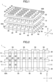
- FIG. 1 is a perspective view illustrating main components of the thermoelectric power-generation device 1 according to the first embodiment of the present invention.
- the thermoelectric power-generation device 1 includes an isolation plate 10, two outer layer isolation plates 20, a plurality of thermoelectric conversion units 30 and 40, and a plurality of electrodes 50.
- the thermoelectric power-generation device 1 causes electrodes 50A and 50B at terminals to generate electric power by a high-temperature medium H and a low-temperature medium C flowing through two flow paths formed by the isolation plate 10 and the two outer layer isolation plates 20 as will be described later in detail.
- side walls (not illustrated in FIG. 1 ) are provided on both sides of the flow paths in the Y direction in order to form the two flow paths in the X direction in the embodiment.
- the isolation plate 10 is a plate-shaped member that has insulating properties, isolates the high-temperature medium H from the low-temperature medium C, and is disposed in the XY plane in the embodiment.
- the isolation plate 10 is made of ceramic, for example, has thermal resistance and corrosion resistance with respect to the media, and has shielding properties that do not allow the media to be transmitted therethrough.
- the two outer layer isolation plates 20 are made of a material that is similar to the material of the isolation plate 10 and are disposed at separate positions on both sides of the isolation plate 10 in the Z direction so as to be parallel to the isolation plate 10.
- the plurality of thermoelectric conversion units 30 and 40 penetrate through the isolation plate 10 and are disposed such that both ends abut on the two outer layer isolation plates 20.
- the thermoelectric conversion units 30 include P-type semiconductor elements and generate electric power by holes therein moving due to a temperature difference between the high-temperature medium H and the low-temperature medium C, as will be described later in detail.
- the thermoelectric conversion units 40 include N-type semiconductor elements and generate electric power by electrons therein moving due to a temperature difference between the high-temperature medium H and the low-temperature medium C, as will be described later in detail.
- the plurality of thermoelectric conversion units 30 and 40 are alternately disposed in a matrix shape in the X direction and the Y direction.
- the plurality of electrodes 50 are made of a metal member such as copper, for example, are provided at the two outer layer isolation plates 20, and electrically connect ends of the alternately adjacent thermoelectric conversion units 30 and 40. In this manner, the electrodes 50 connect all the thermoelectric conversion units 30 and 40 in series. Also, the electrodes 50A and 50B at terminals of the series connection extend outward beyond the outer layer isolation plates 20 as extracting electrodes from which electric power is taken out.
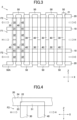
- FIG. 2 is a sectional view of the thermoelectric power-generation device 1 according to the first embodiment of the present invention. More specifically, FIG. 2 illustrates a section of the thermoelectric power-generation device 1 in FIG. 1 in the XZ plane passing through the electrode 50A at the terminal.
- a first flow path F1 is formed between the isolation plate 10 and one of the outer layer isolation plates 20, and the high-temperature medium H as the "first fluid” flows inside the first flow path F1.
- a second flow path F2 is formed between the isolation plate 10 and the other outer layer isolation plates 20, and the low-temperature medium C as the "second fluid” flows inside the second flow path F2.
- the one first flow path F1 and the one second flow path F2 configure the layered flow paths
- the isolation plate 10 isolates the first flow path F1 from the second flow path F2
- the outer layer isolation plates 20 are provided at outermost portions of the layered flow paths in the lamination direction (Z direction) in the embodiment.
- the high-temperature medium H and the low-temperature medium C are assumed to flow in the same direction in the X direction as illustrated in FIG. 2 in the embodiment, the high-temperature medium H and the low-temperature medium C may flow in mutually opposite directions or may flow in mutually vertical directions in the XY plane.
- exhaust gas and cooling water are used as the high-temperature medium H and the low-temperature medium C in a case in which the thermoelectric power-generation device 1 is applied to exhaust gas recirculation (EGR) for a vehicle, for example, the high-temperature medium H and the low-temperature medium C are not necessarily limited thereto and may be any two fluids that have a temperature difference.
- Each thermoelectric conversion unit 30 includes a conductive member 31 and two thermoelectric conversion elements 32.
- the conductive member 31 is made of metal that has electric conductivity such as copper, for example, and is provided so as to block through-holes 11 formed in the isolation plate 10.
- Both the two thermoelectric conversion elements 32 as the "first thermoelectric conversion element” and the “second thermoelectric conversion element” are formed of a known P-type semiconductor material, thus have mutually the same semiconductor polarity, and are disposed such that ends on one side are joined to the conductive member 31 via welding while ends on the other side abut on the outer layer isolation plates 20 in the first flow path F1 and the second flow path F2, respectively.
- both the conductive member 31 and the thermoelectric conversion elements 32 have the same sectional shape in the XY plane. Although the sectional shape is a circular shape in the embodiment, the sectional shape may be another shape.
- Each thermoelectric conversion unit 40 includes a conductive member 41 and two thermoelectric conversion elements 42.
- the conductive member 41 is made of metal that has electric conductivity such as copper, for example, and is provided so as to block the through-holes 11 formed in the isolation plate 10.
- Both the two thermoelectric conversion elements 42 as the "first thermoelectric conversion element” and the “second thermoelectric conversion element” are formed of a known N-type semiconductor material, thus have mutually the same semiconductor polarity, and are disposed such that ends on one side are joined to the conductive member 41 via welding while ends on the other side abut on the outer layer isolation plates 20 in the first flow path F1 and the second flow path F2, respectively.
- both the conductive member 41 and the thermoelectric conversion elements 42 have the same sectional shape in the XY plane. Although the sectional shape is a circular shape in the embodiment, the sectional shape may be another shape.
- the plurality of electrodes 50 are made of metal with electric conductivity such as copper, for example, and electrically connects adjacent thermoelectric conversion units 30 and thermoelectric conversion units 40 with mutually different semiconductor polarities while blocking through-holes 21 formed in the outer layer isolation plates 20.
- the electrodes 50 are secured to the outer layer isolation plates 20 via a swaging structure into the through-holes 21.
- the through-holes 21 are formed to have nonlinear side surfaces in the thickness direction of the outer layer isolation plates 20, that is, the Z direction. Therefore, the electrodes 50 secured to the outer layer isolation plates 20 via the swaging structure have a structure with which the electrodes 50 are unlikely to be separated from the through-holes 21.
- the electrodes 50 are joined directly to the thermoelectric conversion units 30 and the thermoelectric conversion units 40 via welding.
- thermoelectric power-generation device 1 is adapted such that the high-temperature medium H heats the thermoelectric conversion elements 32 and 42 disposed in the first flow path F1, the low-temperature medium C cools the thermoelectric conversion elements 32 and 42 disposed in the second flow path F2, and the thermoelectric conversion units 30 and 40 thus generate electric power in mutually opposite directions with respect to the Z direction. In this manner, the thermoelectric power-generation device 1 can generate electric power using all the thermoelectric conversion units 30 and 40 connected in series.
- thermoelectric power-generation device 1 is adapted such that the portion that comes into contact with the high-temperature medium H is directly heated while the portion that comes into contact with the low-temperature medium C is directly cooled since the individual thermoelectric conversion units 30 and thermoelectric conversion units 40 are disposed so as to straddle the first flow path F1 and the second flow path F2. Therefore, the thermoelectric power-generation device 1 can curb degradation of power generation efficiency (the amount of generated power with respect to the temperature difference between the media) since a loss of heat conduction between the thermoelectric conversion units 30 and 40 and the high-temperature and low-temperature media H and C is reduced.
- thermoelectric power-generation device 1 in the lamination direction can be reduced as compared with the related art in which the thermoelectric conversion module is sandwiched between the flow paths since the thermoelectric conversion units 30 and the thermoelectric conversion units 40 are disposed inside the first flow path F1 and the second flow path F2.
- thermoelectric conversion units 30 and the thermoelectric conversion units 40 are disposed inside the first flow path F1 and the second flow path F2.
- thermoelectric power-generation device 1 is adapted such that the electrodes 50 that connect the thermoelectric conversion units 30 to the thermoelectric conversion units 40 are secured to the outer layer isolation plates 20 via the swaging structure. Therefore, it is possible to reduce a concern that the electrodes 50 are separated from the outer layer isolation plates 20 and to reduce a concern that the high-temperature medium H and the low-temperature medium C flow out of the through-holes 21 by blocking the through-holes 21 formed in the outer layer isolation plates 20.
- thermoelectric power-generation device 2 according to a second embodiment of the present invention will be described.
- the second embodiment of the present invention is different from the aforementioned first embodiment in that layered flow paths include one first flow path F1 and two second flow paths F2 and the thermoelectric conversion units 30 and the thermoelectric conversion units 40 are connected in the Z direction as well.
- layered flow paths include one first flow path F1 and two second flow paths F2 and the thermoelectric conversion units 30 and the thermoelectric conversion units 40 are connected in the Z direction as well.
- FIG. 3 is a sectional view of the thermoelectric power-generation device 2 according to the second embodiment of the present invention. More specifically, FIG. 3 illustrates a section of the thermoelectric power-generation device 2 in the XZ plane similarly to FIG. 2 .
- thermoelectric power-generation device 2 two isolation plates 10 and two outer layer isolation plates 20 are disposed in parallel to each other separately in the Z direction. As illustrated in FIG. 3 , the first flow path F1 is formed between the two isolation plates 10, and the high-temperature medium H as the "first fluid" flows inside the first flow path F1. Also, second flow paths F2 are formed between the two isolation plates 10 and the two outer layer isolation plates 20, and the low-temperature medium C as the "second fluid" flows inside the second flow path F2.
- the layered flow paths are configured such that the one first flow path F1 is sandwiched between the two second flow paths F2, the two isolation plates 10 isolate between the first flow path F1 and the second flow paths F2, and the outer layer isolation plates 20 are provided at outermost portions of the layered flow paths in the lamination direction (Z direction).
- thermoelectric conversion units 30 and thermoelectric conversion units 40 are alternately disposed in the X direction and the Y direction and are also disposed one by one in the Z direction as well. At this time, the thermoelectric conversion units 30 and the thermoelectric conversion units 40 aligned in the Z direction are joined directly to each other via welding in the first flow path F1. Also, the thermoelectric conversion units 30 and the thermoelectric conversion units 40 joined to each other in the Z direction generate electric power in the same direction in the drawing and are electrically connected in series since the thermoelectric conversion units 30 and the thermoelectric conversion units 40 have mutually different semiconductor polarities.
- thermoelectric power-generation device 2 is adapted such that the first flow path F1 and the second flow paths F2 are alternately disposed and the thermoelectric conversion units 30 and the thermoelectric conversion units 40 are joined to each other in the lamination direction.
- thermoelectric power-generation device 2 in the second embodiment of the present invention it is possible to reduce the number of outer layer isolation plates 20 to which the electrodes 50 are swaged and secured and to save the space in the lamination direction as compared with a case in which two thermoelectric power-generation devices 1 as describe above are disposed in the lamination direction.
- thermoelectric conversion units 30 and the thermoelectric conversion units 40 in the lamination direction even in a case in which more first flow paths F1 and second flow paths F2 are alternately disposed with a similar configuration.
- a third embodiment of the present invention will be described.
- a configuration of electrodes 51 provided at the outer layer isolation plates 20 according to the third embodiment of the present invention is different from the aforementioned configuration of the electrodes 50 in the first embodiment.
- points that are different from those in the first embodiment will be described, and detailed description of points that are the same as those in the first embodiment will be omitted.
- FIG. 4 is a sectional view of the electrode 51 according to the third embodiment of the present invention. More specifically, FIG. 4 illustrates a section of one of the electrodes 51 swaged and secured to the outer layer isolation plate 20 in the XZ plane. Although the electrodes 51 provided at the outer layer isolation plate 20 that comes into contact with the first flow path F1 will be described here, description of the electrodes 51 provided at the outer layer isolation plate 20 that comes into contact with the second flow path F2 will be omitted since such electrodes 51 also have a similar configuration.
- a recessed portion 22 for accommodating the electrode 51 that connects the thermoelectric conversion unit 30 to the thermoelectric conversion unit 40 is formed in the outer layer isolation plate 20.
- the recessed portion 22 is formed to face an inner surface 23 of the outer layer isolation plate 20, and the electrode 51 is swaged and secured to the inside thereof. Therefore, it is possible to dispose the electrode 51 so as not to project to the outside of the layered flow paths beyond the outer surface 24 of the outer layer isolation plate 20.
- the third embodiment of the present invention it is possible to obtain the configuration in which the electrodes 51 do not project from the outer layer isolation plates 20 in the lamination direction and to reduce the overall thickness in the lamination direction as compared with the aforementioned first embodiment.
- a fourth embodiment of the present invention will be described.
- a configuration of electrodes 52 provided at the outer layer isolation plates 20 according to the fourth embodiment of the present invention is different from the aforementioned configuration of the electrodes 50 according to the first embodiment.
- points that are different from those in the first embodiment will be described, and detailed description of points that are the same as those in the first embodiment will be omitted.
- FIG. 5 is a sectional view of the electrode 52 according to the fourth embodiment of the present invention. More specifically, FIG. 5 illustrates a section of one of the electrodes 52 swaged and secured to the outer layer isolation plate 20 in the XZ plane. Although the electrodes 52 provided at the outer layer isolation plate 20 that comes into contact with the first flow path F1 will be described here, description of the electrodes 52 provided at the outer layer isolation plate 20 that comes into contact with the second flow path F2 will be omitted since such electrodes 52 can also have a similar configuration.
- a partial through-hole 25 for accommodating the electrode 52 that connects the thermoelectric conversion unit 30 to the thermoelectric conversion unit 40 is formed in the outer layer isolation plate 20.
- the partial through-hole 25 is formed so as to couple a penetrating portion of the outer layer isolation plate 20 to a recessed portion formed so as to face an outer surface 24 of the outer layer isolation plate 20, and the electrode 52 is swaged and secured to the inside thereof. Therefore, it is possible to dispose the electrode 52 so as not to project to the outside of the layered flow paths beyond the outer surface 24 of the outer layer isolation plate 20.
- the fourth embodiment of the present invention it is possible to obtain the configuration in which the electrodes 52 do not project from the outer layer isolation plates 20 in the lamination direction and to reduce the overall thickness in the lamination direction as compared with the aforementioned first embodiment.
- a fifth embodiment of the present invention will be described.
- a configuration of outer layer isolation plates 26 and a configuration of electrodes 53 provided at the outer layer isolation plates 26 according to the fifth embodiment of the present invention are different from that of the outer layer isolation plates 20 and that of the electrodes 50 provided at the outer layer isolation plates 20 according to the aforementioned first embodiment.
- points that are different from those in the first embodiment will be described, and detailed description of points that are the same as those in the first embodiment will be omitted.
- FIG. 6 is an exploded perspective view illustrating a part of the outer layer isolation plates 26 according to the fifth embodiment of the present invention.
- the outer layer isolation plates 26 include a first outer layer isolation plate 27 and a second outer layer isolation plate 29 made of a material that is similar to that of the aforementioned outer layer isolation plates 20 and include a metal plate 28, and the first outer layer isolation plate 27 and the second outer layer isolation plate 29 are attached to both surfaces of the metal plate 28.
- the outer layer isolation plates 26 can be formed to be thinner than the aforementioned outer layer isolation plates 20.
- Each of the electrodes 53 swaged and secured to the outer layer isolation plates 26 is configured to have a shape including a first portion electrode 54, a second portion electrode 55, a third portion electrode 56, and a fourth portion electrode 57 in accordance with the layered structure of the outer layer isolation plates 26.
- the first portion electrode 54 is disposed in the same layer as the first outer layer isolation plate 27 so as to block a through-hole formed in the first outer layer isolation plate 27.
- the second portion electrode 55 is disposed in the same layer as the first outer layer isolation plate 27 with a clearance provided with respect to a hole portion 28a formed in the metal plate 28.
- the third portion electrode 56 is disposed in the same layer as the second outer layer isolation plate 29 so as to block a through-hole formed in the second outer layer isolation plate 29.
- the fourth portion electrode 57 electrically connects two adjacent third portion electrodes 56 on the outer surface of the second outer layer isolation plate 29.
- first portion electrode 54 to the fourth portion electrode 57 are described separately here, all of the first portion electrode 54 to the fourth portion electrode 57 are made of the same material and are integrally formed as the electrode 53. Also, since the first outer layer isolation plate 27 and the second outer layer isolation plate 29 are formed of an insulating material while the metal plate 28 has conductivity, a configuration in electrical continuity with the thermoelectric conversion units 30 and the thermoelectric conversion units 40 is not established via the electrodes 53 is obtained by providing a plurality of hole portions 28a.
- FIG. 7 is a sectional view of a thermoelectric power-generation device 3 according to the fifth embodiment of the present invention. More specifically, FIG. 7 illustrates a section of the thermoelectric power-generation device 3 in a case in which the first outer layer isolation plate 27 and the second outer layer isolation plate 29 include the metal plate 28 in the YZ plane passing through an electrode 53A at the terminal. In other words, FIG. 7 illustrates a section when seen from the upstream side of the high-temperature medium H an the low-temperature medium C.
- the thermoelectric power-generation device 3 is provided with side walls 70 that prevent the high-temperature medium H and the low-temperature medium C flowing in the X direction from flowing out in the Y direction.
- the side walls 70 may be made of a material that is similar to the material of the isolation plate 10 and the outer layer isolation plates 26 and may be formed integrally with the isolation plate 10 and the outer layer isolation plates 26.
- the outer layer isolation plates 26 are formed to include the aforementioned metal plate 28.
- the metal plate 28 is formed to be longer than the outer layer isolation plate 26 in the Y direction in the embodiment.
- the metal plate 28 can be used as a securing member for easily securing the thermoelectric power-generation device 3 to a mounting location.
- the thermoelectric power-generation device 3 includes a metal case body 60 as illustrated in FIG. 7 , for example, it is possible to connect the metal plate 28 to an inner wall surfaces of the case body 60 via welding.
- the outer layer isolation plates 26 are formed of ceramic, for example, it is possible to more strongly secure the thermoelectric power-generation device 3 by establishing the connection via the metal plate 28 than by connecting the thermoelectric power-generation device 3 directly to the case body 60.
- the metal plate 28 comes into contact with neither the high-temperature medium H nor the low-temperature medium C, it is possible to prevent corrosion due to the high-temperature medium H or the low-temperature medium C.
- a sixth embodiment of the present invention will be described.
- a configuration of electrodes 58 according to the sixth embodiment of the present invention is different from the configuration of the electrodes 53 according to the aforementioned fifth embodiment.
- points that are different from those in the fifth embodiment will be described, and detailed description of points that are the same as those in the fifth embodiment will be omitted.
- FIG. 8 is a sectional view of the electrode 58 according to the sixth embodiment of the present invention. More specifically, FIG. 8 illustrates a section of one of the electrodes 58 swaged and secured to the outer layer isolation plate 26 in the XZ plane. Although the electrodes 58 provided at the outer layer isolation plate 26 that comes into contact with the first flow path F1 will be described here, description of the electrodes 58 provided at the outer layer isolation plate 26 that comes into contact with the second flow path F2 will be omitted since such electrodes 58 can have a similar configuration.
- Each of the electrodes 58 is configured of two penetrating portions that penetrate through the first outer layer isolation plate 27 and that are connected to each of the thermoelectric conversion unit 30 and the thermoelectric conversion unit 40 and a connecting portion that connects the two penetrating portions in the same layer as the first outer layer isolation plate 27.
- a seventh embodiment of the present invention will be described.
- the seventh embodiment of the present invention is different from the aforementioned first embodiment in configurations of the thermoelectric conversion units 30 and the thermoelectric conversion units 40.
- points that are different from those in the first embodiment will be described, and detailed description of points that are the same as those in the first embodiment will be omitted.
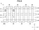
- FIG. 9 is a sectional view of a thermoelectric power generation device 4 according to the seventh embodiment of the present invention. More specifically, FIG. 9 illustrates a section in the XZ plane passing through an electrode 50A at the terminal.
- thermoelectric conversion units 30 are configured of P-type semiconductor elements 33 that penetrate through the isolation plate 10 between the two outer layer isolation plates 20.
- thermoelectric conversion units 40 according to the embodiment are configured of N-type semiconductor elements 43 that penetrate through the isolation plate 10 between the two outer layer isolation plates 20.
- thermoelectric conversion units 30 and 40 of the embodiment it is possible to secure sealing properties by blocking the clearance with a plating member 12, for example.
- thermoelectric conversion units 30 and the thermoelectric conversion units 40 of the embodiment it is possible to obtain effects and advantages that are similar to those in the aforementioned first embodiment even with the configuration in which the individual semiconductor elements penetrate through the isolation plate 10.
- the present invention is not limited to the aforementioned embodiments.
- the disposition of the first flow path F1 and the second flow path F2 may be opposite to configure the layered flow paths in each of the aforementioned embodiments.
- the aspect in which the first flow path F1 and the second flow path F2 are laminated in the Z direction to configure the layered flow paths has been exemplified in each of the aforementioned embodiments, the first flow path F1 and the second flow path F2 may be laminated in a radial direction of concentric circles to configure layered flow paths.
- the conductive members 31 and 41 illustrated in FIGS. 2 and 3 may be secured to the through-holes 11 in the isolation plate 10 via a swaging structure similarly to the electrodes 50.
- the isolation plate 10 may be provided with the metal plate 28 similarly to the outer layer isolation plates 26 illustrated in FIGS. 6 and 7 .
- the isolation plate 10 may have double structures.
- the overall thickness of the isolation plate 10 with the double structures is suitably set to a thickness that is substantially the same as the thickness of the isolation plate 10 in each of the aforementioned embodiments. In this manner, the isolation plate 10 with the double structures can reliably prevent the high-temperature medium H and the low-temperature medium C from being mixed due to leakage without leading an increase in overall thickness in the lamination direction.
- the through-holes 11 are formed in each of the isolation plate 10 with the double structures in this case, it is possible to apply conductive members 31 and 41 with substantially the same dimensions as those in each of the aforementioned embodiments to the conductive members 31 and 41 provided at the through-holes 11.
- the widths of the thermoelectric conversion units 30 and the thermoelectric conversion units 40 may differently be set by providing a difference between the sectional area of the thermoelectric conversion units 30 and the sectional area of the thermoelectric conversion units 40 in each of the aforementioned embodiments.
- elements of a type of either one of the thermoelectric conversion elements 32 configured of the P-type semiconductor material or the thermoelectric conversion elements 42 configured of the N-type semiconductor material have higher resistance values than semiconductor material have higher resistance values than resistance values of elements of the other type
Landscapes
- Hybrid Cells (AREA)
- Fuel Cell (AREA)
- Electrolytic Production Of Non-Metals, Compounds, Apparatuses Therefor (AREA)
- Measuring Temperature Or Quantity Of Heat (AREA)
Claims (7)
- Dispositif de génération d'énergie thermoélectrique (1) comprenant :un premier chemin d'écoulement (F1) à travers lequel un premier fluide (H) s'écoule ;un second chemin d'écoulement (F2) à travers lequel un second fluide (C) qui possède une différence de température par rapport au premier fluide (H) s'écoule ;une plaque d'isolation isolante (10) configurée pour isoler le premier chemin d'écoulement (F1) vis-à-vis du second chemin d'écoulement (F2) ;des plaques d'isolation de couche externe isolantes (20) ménagées au niveau de portions les plus externes de chemins d'écoulement en couches comportant le premier chemin d'écoulement (F1) et le second chemin d'écoulement (F2) ;une pluralité d'unités de conversion thermoélectrique (30, 40) configurées pour générer de l'énergie à l'aide de la différence de température ; etdes électrodes (50) ménagées au niveau des plaques d'isolation de couche externe isolantes (20) et configurées pour relier les unités de conversion thermoélectrique (30, 40) ayant des polarités de semi-conducteur mutuellement différentes en série,dans lequel la pluralité d'unités de conversion thermoélectrique (30, 40) sont disposées de façon à chevaucher le premier chemin d'écoulement (F1) et le second chemin d'écoulement (F2),la pluralité d'unités de conversion thermoélectrique (30, 40) comportent des organes conducteurs (31, 41) configurés pour s'étendre jusque dans et bloquer des trous traversants (11) formés dans la plaque d'isolation isolante (10), des premiers éléments de conversion thermoélectrique disposés au niveau du premier chemin d'écoulement (F1) et reliés aux organes conducteurs (31, 41), et des seconds éléments de conversion thermoélectrique disposés au niveau du second chemin d'écoulement (F2), les premier et second éléments de conversion thermoélectrique (32, 42) étant reliés aux organes conducteurs (31, 41), et ayant les mêmes formes de section que les organes conducteurs (31, 41), et les premiers éléments de conversion thermoélectrique et les seconds éléments de conversion thermoélectrique possèdent une polarité de semi-conducteur mutuellement identique.
- Dispositif de génération d'énergie thermoélectrique (1) selon la revendication 1,dans lequel le premier chemin d'écoulement (F1) est disposé de façon à être pris en sandwich par une pluralité de seconds chemins d'écoulement (F2), etla pluralité d'unités de conversion thermoélectrique (30, 40) sont conçues de sorte que les unités de conversion thermoélectrique (30, 40) ayant des polarités de semi-conducteur mutuellement différentes soient jointes les unes aux autres au niveau du premier chemin d'écoulement (F1).
- Dispositif de génération d'énergie thermoélectrique (1) selon la revendication 1 ou 2, dans lequel les électrodes (50) sont fixées aux plaques d'isolation de couche externe isolantes (20) avec une structure de sertissage.
- Dispositif de génération d'énergie thermoélectrique (1) selon l'une quelconque des revendications 1 à 3, dans lequel les électrodes (50) sont disposées de façon à ne pas faire saillie vers l'extérieur au-delà d'une surface externe des plaques d'isolation de couche externe isolantes (20).
- Dispositif de génération d'énergie thermoélectrique (1) selon l'une quelconque des revendications 1 à 4, dans lequel les électrodes (50) ne sont pas en contact avec le premier fluide (H) et le second fluide (C).
- Dispositif de génération d'énergie thermoélectrique (1) selon l'une quelconque des revendications 1 à 5,
dans lequel au moins l'une parmi les plaques d'isolation de couche externe isolantes (20) et la plaque d'isolation isolante (10) comporte une plaque métallique (28) qui ne possède pas de continuité électrique avec les unités de conversion thermoélectrique (30, 40). - Dispositif de génération d'énergie thermoélectrique (1) selon la revendication 6, dans lequel la plaque métallique (28) est disposée de façon à ne pas être en contact avec le premier fluide (H) et le second fluide (C).
Applications Claiming Priority (2)
| Application Number | Priority Date | Filing Date | Title |
|---|---|---|---|
| JP2018049649A JP7278030B2 (ja) | 2018-03-16 | 2018-03-16 | 熱電発電装置 |
| PCT/JP2019/006541 WO2019176495A1 (fr) | 2018-03-16 | 2019-02-21 | Dispositif de génération d'énergie thermoélectrique |
Publications (3)
| Publication Number | Publication Date |
|---|---|
| EP3767690A1 EP3767690A1 (fr) | 2021-01-20 |
| EP3767690A4 EP3767690A4 (fr) | 2021-12-22 |
| EP3767690B1 true EP3767690B1 (fr) | 2025-06-18 |
Family
ID=67907598
Family Applications (1)
| Application Number | Title | Priority Date | Filing Date |
|---|---|---|---|
| EP19768572.0A Active EP3767690B1 (fr) | 2018-03-16 | 2019-02-21 | Dispositif de génération d'énergie thermoélectrique |
Country Status (7)
| Country | Link |
|---|---|
| US (1) | US11557707B2 (fr) |
| EP (1) | EP3767690B1 (fr) |
| JP (1) | JP7278030B2 (fr) |
| KR (1) | KR102428364B1 (fr) |
| CN (1) | CN111989790B (fr) |
| CA (1) | CA3087991C (fr) |
| WO (1) | WO2019176495A1 (fr) |
Families Citing this family (1)
| Publication number | Priority date | Publication date | Assignee | Title |
|---|---|---|---|---|
| KR20230085571A (ko) * | 2021-12-07 | 2023-06-14 | 삼성전기주식회사 | 열전 모듈 및 그 제조 방법 |
Family Cites Families (16)
| Publication number | Priority date | Publication date | Assignee | Title |
|---|---|---|---|---|
| US4687879A (en) * | 1985-04-25 | 1987-08-18 | Varo, Inc. | Tiered thermoelectric unit and method of fabricating same |
| NL8801093A (nl) * | 1988-04-27 | 1989-11-16 | Theodorus Bijvoets | Thermo-electrische inrichting. |
| JPH0544473Y2 (fr) * | 1988-09-30 | 1993-11-11 | ||
| JP2000009361A (ja) | 1998-06-22 | 2000-01-14 | Itsuo Onaka | 熱電変換システム |
| US6121539A (en) * | 1998-08-27 | 2000-09-19 | International Business Machines Corporation | Thermoelectric devices and methods for making the same |
| US7235735B2 (en) * | 2002-04-15 | 2007-06-26 | Nextreme Thermal Solutions, Inc. | Thermoelectric devices utilizing double-sided Peltier junctions and methods of making the devices |
| US7763792B2 (en) * | 2005-02-14 | 2010-07-27 | Marlow Industries, Inc. | Multistage heat pumps and method of manufacture |
| JP4719747B2 (ja) | 2005-08-31 | 2011-07-06 | 日立オートモティブシステムズ株式会社 | Egrガス発電装置 |
| JP4785476B2 (ja) | 2005-09-20 | 2011-10-05 | 大阪瓦斯株式会社 | 熱電発電構造及び発電機能付き熱交換器 |
| JP5106944B2 (ja) | 2007-08-06 | 2012-12-26 | 株式会社アツミテック | 発電装置 |
| JP2009081970A (ja) * | 2007-09-27 | 2009-04-16 | Ihi Marine United Inc | 熱電発電装置及び該熱電発電装置を用いた発電システム |
| JP2009117645A (ja) | 2007-11-07 | 2009-05-28 | Showa Denko Kk | 熱電素子用電極および熱電モジュール |
| JP2013012597A (ja) * | 2011-05-31 | 2013-01-17 | Imasen Electric Ind Co Ltd | 熱交換器 |
| KR101680422B1 (ko) * | 2014-01-13 | 2016-11-28 | 홍익대학교 산학협력단 | 써멀비아전극을 구비한 열전모듈 및 그 제조방법 |
| CN105742475A (zh) * | 2014-12-11 | 2016-07-06 | 厦门兰智科技有限公司 | 一种热电转换装置结构 |
| KR20160119465A (ko) * | 2015-04-06 | 2016-10-14 | 김경민 | 열전소자를 이용한 촛불발전기 |
-
2018
- 2018-03-16 JP JP2018049649A patent/JP7278030B2/ja active Active
-
2019
- 2019-02-21 US US16/961,531 patent/US11557707B2/en active Active
- 2019-02-21 CA CA3087991A patent/CA3087991C/fr active Active
- 2019-02-21 CN CN201980018306.0A patent/CN111989790B/zh active Active
- 2019-02-21 WO PCT/JP2019/006541 patent/WO2019176495A1/fr not_active Ceased
- 2019-02-21 EP EP19768572.0A patent/EP3767690B1/fr active Active
- 2019-02-21 KR KR1020207021957A patent/KR102428364B1/ko active Active
Also Published As
| Publication number | Publication date |
|---|---|
| WO2019176495A1 (fr) | 2019-09-19 |
| JP7278030B2 (ja) | 2023-05-19 |
| KR20200100180A (ko) | 2020-08-25 |
| CA3087991C (fr) | 2023-10-10 |
| US20210057627A1 (en) | 2021-02-25 |
| CN111989790B (zh) | 2024-08-13 |
| CN111989790A8 (zh) | 2021-01-22 |
| KR102428364B1 (ko) | 2022-08-02 |
| CN111989790A (zh) | 2020-11-24 |
| EP3767690A4 (fr) | 2021-12-22 |
| CA3087991A1 (fr) | 2019-09-19 |
| JP2019161169A (ja) | 2019-09-19 |
| US11557707B2 (en) | 2023-01-17 |
| EP3767690A1 (fr) | 2021-01-20 |
Similar Documents
| Publication | Publication Date | Title |
|---|---|---|
| US9349934B2 (en) | Method for manufacturing a thermoelectric device, especially intended to generate an electrical current in an automotive vehicle | |
| US8648246B2 (en) | Thermoelectric module and power generation apparatus | |
| CN103180984A (zh) | 用于热电模块的半导体元件及其制造方法 | |
| US9209377B2 (en) | Thermoelectric module for a thermoelectric generator of a vehicle with a sealing element and vehicle having the thermoelectric module | |
| WO2018105601A1 (fr) | Unité de conversion thermoélectrique, système de production d'énergie et procédé de conversion thermoélectrique | |
| JP2016072579A (ja) | 熱電変換モジュール | |
| EP3767690B1 (fr) | Dispositif de génération d'énergie thermoélectrique | |
| CN107004754A (zh) | 热电发电单元及其制作和使用方法 | |
| TW201523938A (zh) | 具有經由配線圖案而連接的熱電變換元件之熱電變換裝置及其製造方法 | |
| US20070199587A1 (en) | Thermoelectric Conversion Module | |
| JP2006086210A (ja) | 熱電変換システム | |
| KR20130073554A (ko) | 열전 모듈 및 열전 모듈의 제조방법 | |
| CN103503184B (zh) | 车辆热电发电机的热电模块 | |
| KR20160143716A (ko) | 특히 자동차에서 전류를 발생시키도록 구성된 열전 장치 및 열전 모듈 | |
| JP2015233063A (ja) | 熱電変換システム | |
| JP2884070B2 (ja) | 熱電変換モジュール | |
| TW201351733A (zh) | 用於熱電模組之半導體元件及熱電模組 | |
| US20140338714A1 (en) | Thermoelectric Assembly And Device, In Particular For Generating An Electric Current In A Motor Vehicle | |
| JP7642654B2 (ja) | 発電装置 | |
| KR102021664B1 (ko) | 다중 다열 배열식 열전 발전장치 및 그 제조방법 | |
| EP3428981B1 (fr) | Module de conversion thermoélectrique | |
| CN109841725B (zh) | 热电模块板和包括它的热电模块组件 | |
| US20190088848A1 (en) | Thermoelectric conversion module and thermoelectric conversion element | |
| KR20130019883A (ko) | 열전 모듈 및 열전 모듈의 제조방법 | |
| CN103814451B (zh) | 热电发电装置 |
Legal Events
| Date | Code | Title | Description |
|---|---|---|---|
| STAA | Information on the status of an ep patent application or granted ep patent |
Free format text: STATUS: THE INTERNATIONAL PUBLICATION HAS BEEN MADE |
|
| PUAI | Public reference made under article 153(3) epc to a published international application that has entered the european phase |
Free format text: ORIGINAL CODE: 0009012 |
|
| STAA | Information on the status of an ep patent application or granted ep patent |
Free format text: STATUS: REQUEST FOR EXAMINATION WAS MADE |
|
| 17P | Request for examination filed |
Effective date: 20200813 |
|
| AK | Designated contracting states |
Kind code of ref document: A1 Designated state(s): AL AT BE BG CH CY CZ DE DK EE ES FI FR GB GR HR HU IE IS IT LI LT LU LV MC MK MT NL NO PL PT RO RS SE SI SK SM TR |
|
| AX | Request for extension of the european patent |
Extension state: BA ME |
|
| DAV | Request for validation of the european patent (deleted) | ||
| DAX | Request for extension of the european patent (deleted) | ||
| A4 | Supplementary search report drawn up and despatched |
Effective date: 20211124 |
|
| RIC1 | Information provided on ipc code assigned before grant |
Ipc: H02N 11/00 20060101ALI20211118BHEP Ipc: H01L 35/30 20060101ALI20211118BHEP Ipc: H01L 35/32 20060101AFI20211118BHEP |
|
| REG | Reference to a national code |
Ref country code: DE Ref legal event code: R079 Free format text: PREVIOUS MAIN CLASS: H01L0035320000 Ipc: H10N0010130000 Ref document number: 602019071278 Country of ref document: DE |
|
| GRAP | Despatch of communication of intention to grant a patent |
Free format text: ORIGINAL CODE: EPIDOSNIGR1 |
|
| STAA | Information on the status of an ep patent application or granted ep patent |
Free format text: STATUS: GRANT OF PATENT IS INTENDED |
|
| RIC1 | Information provided on ipc code assigned before grant |
Ipc: H10N 10/81 20230101ALI20250204BHEP Ipc: H10N 10/17 20230101ALI20250204BHEP Ipc: H10N 10/13 20230101AFI20250204BHEP |
|
| INTG | Intention to grant announced |
Effective date: 20250228 |
|
| GRAS | Grant fee paid |
Free format text: ORIGINAL CODE: EPIDOSNIGR3 |
|
| GRAA | (expected) grant |
Free format text: ORIGINAL CODE: 0009210 |
|
| STAA | Information on the status of an ep patent application or granted ep patent |
Free format text: STATUS: THE PATENT HAS BEEN GRANTED |
|
| AK | Designated contracting states |
Kind code of ref document: B1 Designated state(s): AL AT BE BG CH CY CZ DE DK EE ES FI FR GB GR HR HU IE IS IT LI LT LU LV MC MK MT NL NO PL PT RO RS SE SI SK SM TR |
|
| REG | Reference to a national code |
Ref country code: GB Ref legal event code: FG4D |
|
| REG | Reference to a national code |
Ref country code: CH Ref legal event code: EP |
|
| REG | Reference to a national code |
Ref country code: DE Ref legal event code: R096 Ref document number: 602019071278 Country of ref document: DE |
|
| REG | Reference to a national code |
Ref country code: CH Ref legal event code: EP |
|
| REG | Reference to a national code |
Ref country code: IE Ref legal event code: FG4D |
|
| PG25 | Lapsed in a contracting state [announced via postgrant information from national office to epo] |
Ref country code: FI Free format text: LAPSE BECAUSE OF FAILURE TO SUBMIT A TRANSLATION OF THE DESCRIPTION OR TO PAY THE FEE WITHIN THE PRESCRIBED TIME-LIMIT Effective date: 20250618 |
|
| REG | Reference to a national code |
Ref country code: LT Ref legal event code: MG9D |
|
| PG25 | Lapsed in a contracting state [announced via postgrant information from national office to epo] |
Ref country code: NO Free format text: LAPSE BECAUSE OF FAILURE TO SUBMIT A TRANSLATION OF THE DESCRIPTION OR TO PAY THE FEE WITHIN THE PRESCRIBED TIME-LIMIT Effective date: 20250918 Ref country code: GR Free format text: LAPSE BECAUSE OF FAILURE TO SUBMIT A TRANSLATION OF THE DESCRIPTION OR TO PAY THE FEE WITHIN THE PRESCRIBED TIME-LIMIT Effective date: 20250919 |
|
| PG25 | Lapsed in a contracting state [announced via postgrant information from national office to epo] |
Ref country code: BG Free format text: LAPSE BECAUSE OF FAILURE TO SUBMIT A TRANSLATION OF THE DESCRIPTION OR TO PAY THE FEE WITHIN THE PRESCRIBED TIME-LIMIT Effective date: 20250618 |
|
| PG25 | Lapsed in a contracting state [announced via postgrant information from national office to epo] |
Ref country code: HR Free format text: LAPSE BECAUSE OF FAILURE TO SUBMIT A TRANSLATION OF THE DESCRIPTION OR TO PAY THE FEE WITHIN THE PRESCRIBED TIME-LIMIT Effective date: 20250618 |
|
| PG25 | Lapsed in a contracting state [announced via postgrant information from national office to epo] |
Ref country code: RS Free format text: LAPSE BECAUSE OF FAILURE TO SUBMIT A TRANSLATION OF THE DESCRIPTION OR TO PAY THE FEE WITHIN THE PRESCRIBED TIME-LIMIT Effective date: 20250918 |
|
| REG | Reference to a national code |
Ref country code: NL Ref legal event code: MP Effective date: 20250618 |
|
| PG25 | Lapsed in a contracting state [announced via postgrant information from national office to epo] |
Ref country code: LV Free format text: LAPSE BECAUSE OF FAILURE TO SUBMIT A TRANSLATION OF THE DESCRIPTION OR TO PAY THE FEE WITHIN THE PRESCRIBED TIME-LIMIT Effective date: 20250618 |
|
| PG25 | Lapsed in a contracting state [announced via postgrant information from national office to epo] |
Ref country code: NL Free format text: LAPSE BECAUSE OF FAILURE TO SUBMIT A TRANSLATION OF THE DESCRIPTION OR TO PAY THE FEE WITHIN THE PRESCRIBED TIME-LIMIT Effective date: 20250618 |
|
| PG25 | Lapsed in a contracting state [announced via postgrant information from national office to epo] |
Ref country code: PT Free format text: LAPSE BECAUSE OF FAILURE TO SUBMIT A TRANSLATION OF THE DESCRIPTION OR TO PAY THE FEE WITHIN THE PRESCRIBED TIME-LIMIT Effective date: 20251020 |
|
| REG | Reference to a national code |
Ref country code: AT Ref legal event code: MK05 Ref document number: 1805436 Country of ref document: AT Kind code of ref document: T Effective date: 20250618 |
|
| PG25 | Lapsed in a contracting state [announced via postgrant information from national office to epo] |
Ref country code: IS Free format text: LAPSE BECAUSE OF FAILURE TO SUBMIT A TRANSLATION OF THE DESCRIPTION OR TO PAY THE FEE WITHIN THE PRESCRIBED TIME-LIMIT Effective date: 20251018 |
|
| PG25 | Lapsed in a contracting state [announced via postgrant information from national office to epo] |
Ref country code: AT Free format text: LAPSE BECAUSE OF FAILURE TO SUBMIT A TRANSLATION OF THE DESCRIPTION OR TO PAY THE FEE WITHIN THE PRESCRIBED TIME-LIMIT Effective date: 20250618 Ref country code: SM Free format text: LAPSE BECAUSE OF FAILURE TO SUBMIT A TRANSLATION OF THE DESCRIPTION OR TO PAY THE FEE WITHIN THE PRESCRIBED TIME-LIMIT Effective date: 20250618 |
|
| PG25 | Lapsed in a contracting state [announced via postgrant information from national office to epo] |
Ref country code: CZ Free format text: LAPSE BECAUSE OF FAILURE TO SUBMIT A TRANSLATION OF THE DESCRIPTION OR TO PAY THE FEE WITHIN THE PRESCRIBED TIME-LIMIT Effective date: 20250618 |
|
| PG25 | Lapsed in a contracting state [announced via postgrant information from national office to epo] |
Ref country code: PL Free format text: LAPSE BECAUSE OF FAILURE TO SUBMIT A TRANSLATION OF THE DESCRIPTION OR TO PAY THE FEE WITHIN THE PRESCRIBED TIME-LIMIT Effective date: 20250618 |
|
| PG25 | Lapsed in a contracting state [announced via postgrant information from national office to epo] |
Ref country code: EE Free format text: LAPSE BECAUSE OF FAILURE TO SUBMIT A TRANSLATION OF THE DESCRIPTION OR TO PAY THE FEE WITHIN THE PRESCRIBED TIME-LIMIT Effective date: 20250618 |
|
| PG25 | Lapsed in a contracting state [announced via postgrant information from national office to epo] |
Ref country code: RO Free format text: LAPSE BECAUSE OF FAILURE TO SUBMIT A TRANSLATION OF THE DESCRIPTION OR TO PAY THE FEE WITHIN THE PRESCRIBED TIME-LIMIT Effective date: 20250618 Ref country code: SK Free format text: LAPSE BECAUSE OF FAILURE TO SUBMIT A TRANSLATION OF THE DESCRIPTION OR TO PAY THE FEE WITHIN THE PRESCRIBED TIME-LIMIT Effective date: 20250618 |
|
| PG25 | Lapsed in a contracting state [announced via postgrant information from national office to epo] |
Ref country code: ES Free format text: LAPSE BECAUSE OF FAILURE TO SUBMIT A TRANSLATION OF THE DESCRIPTION OR TO PAY THE FEE WITHIN THE PRESCRIBED TIME-LIMIT Effective date: 20250618 |
|
| PGFP | Annual fee paid to national office [announced via postgrant information from national office to epo] |
Ref country code: GB Payment date: 20260220 Year of fee payment: 8 |
|
| PG25 | Lapsed in a contracting state [announced via postgrant information from national office to epo] |
Ref country code: DK Free format text: LAPSE BECAUSE OF FAILURE TO SUBMIT A TRANSLATION OF THE DESCRIPTION OR TO PAY THE FEE WITHIN THE PRESCRIBED TIME-LIMIT Effective date: 20250618 |
|
| PGFP | Annual fee paid to national office [announced via postgrant information from national office to epo] |
Ref country code: DE Payment date: 20260218 Year of fee payment: 8 |
|
| PG25 | Lapsed in a contracting state [announced via postgrant information from national office to epo] |
Ref country code: IT Free format text: LAPSE BECAUSE OF FAILURE TO SUBMIT A TRANSLATION OF THE DESCRIPTION OR TO PAY THE FEE WITHIN THE PRESCRIBED TIME-LIMIT Effective date: 20250618 |
|
| PGFP | Annual fee paid to national office [announced via postgrant information from national office to epo] |
Ref country code: FR Payment date: 20260218 Year of fee payment: 8 |
|
| PLBE | No opposition filed within time limit |
Free format text: ORIGINAL CODE: 0009261 |
|
| STAA | Information on the status of an ep patent application or granted ep patent |
Free format text: STATUS: NO OPPOSITION FILED WITHIN TIME LIMIT |