EP3767732A1 - Bloc-batterie - Google Patents
Bloc-batterie Download PDFInfo
- Publication number
- EP3767732A1 EP3767732A1 EP20185948.5A EP20185948A EP3767732A1 EP 3767732 A1 EP3767732 A1 EP 3767732A1 EP 20185948 A EP20185948 A EP 20185948A EP 3767732 A1 EP3767732 A1 EP 3767732A1
- Authority
- EP
- European Patent Office
- Prior art keywords
- battery pack
- cell carrier
- cell
- battery
- receiving space
- Prior art date
- Legal status (The legal status is an assumption and is not a legal conclusion. Google has not performed a legal analysis and makes no representation as to the accuracy of the status listed.)
- Granted
Links
Images



Classifications
-
- H—ELECTRICITY
- H01—ELECTRIC ELEMENTS
- H01M—PROCESSES OR MEANS, e.g. BATTERIES, FOR THE DIRECT CONVERSION OF CHEMICAL ENERGY INTO ELECTRICAL ENERGY
- H01M10/00—Secondary cells; Manufacture thereof
- H01M10/42—Methods or arrangements for servicing or maintenance of secondary cells or secondary half-cells
- H01M10/4207—Methods or arrangements for servicing or maintenance of secondary cells or secondary half-cells for several batteries or cells simultaneously or sequentially
-
- H—ELECTRICITY
- H01—ELECTRIC ELEMENTS
- H01M—PROCESSES OR MEANS, e.g. BATTERIES, FOR THE DIRECT CONVERSION OF CHEMICAL ENERGY INTO ELECTRICAL ENERGY
- H01M50/00—Constructional details or processes of manufacture of the non-active parts of electrochemical cells other than fuel cells, e.g. hybrid cells
- H01M50/20—Mountings; Secondary casings or frames; Racks, modules or packs; Suspension devices; Shock absorbers; Transport or carrying devices; Holders
- H01M50/247—Mountings; Secondary casings or frames; Racks, modules or packs; Suspension devices; Shock absorbers; Transport or carrying devices; Holders specially adapted for portable devices, e.g. mobile phones, computers, hand tools or pacemakers
-
- B—PERFORMING OPERATIONS; TRANSPORTING
- B25—HAND TOOLS; PORTABLE POWER-DRIVEN TOOLS; MANIPULATORS
- B25F—COMBINATION OR MULTI-PURPOSE TOOLS NOT OTHERWISE PROVIDED FOR; DETAILS OR COMPONENTS OF PORTABLE POWER-DRIVEN TOOLS NOT PARTICULARLY RELATED TO THE OPERATIONS PERFORMED AND NOT OTHERWISE PROVIDED FOR
- B25F5/00—Details or components of portable power-driven tools not particularly related to the operations performed and not otherwise provided for
- B25F5/008—Cooling means
-
- H—ELECTRICITY
- H01—ELECTRIC ELEMENTS
- H01M—PROCESSES OR MEANS, e.g. BATTERIES, FOR THE DIRECT CONVERSION OF CHEMICAL ENERGY INTO ELECTRICAL ENERGY
- H01M10/00—Secondary cells; Manufacture thereof
- H01M10/42—Methods or arrangements for servicing or maintenance of secondary cells or secondary half-cells
- H01M10/425—Structural combination with electronic components, e.g. electronic circuits integrated to the outside of the casing
-
- H—ELECTRICITY
- H01—ELECTRIC ELEMENTS
- H01M—PROCESSES OR MEANS, e.g. BATTERIES, FOR THE DIRECT CONVERSION OF CHEMICAL ENERGY INTO ELECTRICAL ENERGY
- H01M50/00—Constructional details or processes of manufacture of the non-active parts of electrochemical cells other than fuel cells, e.g. hybrid cells
- H01M50/20—Mountings; Secondary casings or frames; Racks, modules or packs; Suspension devices; Shock absorbers; Transport or carrying devices; Holders
- H01M50/204—Racks, modules or packs for multiple batteries or multiple cells
- H01M50/207—Racks, modules or packs for multiple batteries or multiple cells characterised by their shape
- H01M50/213—Racks, modules or packs for multiple batteries or multiple cells characterised by their shape adapted for cells having curved cross-section, e.g. round or elliptic
-
- H—ELECTRICITY
- H01—ELECTRIC ELEMENTS
- H01M—PROCESSES OR MEANS, e.g. BATTERIES, FOR THE DIRECT CONVERSION OF CHEMICAL ENERGY INTO ELECTRICAL ENERGY
- H01M50/00—Constructional details or processes of manufacture of the non-active parts of electrochemical cells other than fuel cells, e.g. hybrid cells
- H01M50/20—Mountings; Secondary casings or frames; Racks, modules or packs; Suspension devices; Shock absorbers; Transport or carrying devices; Holders
- H01M50/233—Mountings; Secondary casings or frames; Racks, modules or packs; Suspension devices; Shock absorbers; Transport or carrying devices; Holders characterised by physical properties of casings or racks, e.g. dimensions
- H01M50/24—Mountings; Secondary casings or frames; Racks, modules or packs; Suspension devices; Shock absorbers; Transport or carrying devices; Holders characterised by physical properties of casings or racks, e.g. dimensions adapted for protecting batteries from their environment, e.g. from corrosion
-
- H—ELECTRICITY
- H01—ELECTRIC ELEMENTS
- H01M—PROCESSES OR MEANS, e.g. BATTERIES, FOR THE DIRECT CONVERSION OF CHEMICAL ENERGY INTO ELECTRICAL ENERGY
- H01M2220/00—Batteries for particular applications
- H01M2220/30—Batteries in portable systems, e.g. mobile phone, laptop
-
- H—ELECTRICITY
- H01—ELECTRIC ELEMENTS
- H01M—PROCESSES OR MEANS, e.g. BATTERIES, FOR THE DIRECT CONVERSION OF CHEMICAL ENERGY INTO ELECTRICAL ENERGY
- H01M50/00—Constructional details or processes of manufacture of the non-active parts of electrochemical cells other than fuel cells, e.g. hybrid cells
- H01M50/20—Mountings; Secondary casings or frames; Racks, modules or packs; Suspension devices; Shock absorbers; Transport or carrying devices; Holders
- H01M50/271—Lids or covers for the racks or secondary casings
-
- Y—GENERAL TAGGING OF NEW TECHNOLOGICAL DEVELOPMENTS; GENERAL TAGGING OF CROSS-SECTIONAL TECHNOLOGIES SPANNING OVER SEVERAL SECTIONS OF THE IPC; TECHNICAL SUBJECTS COVERED BY FORMER USPC CROSS-REFERENCE ART COLLECTIONS [XRACs] AND DIGESTS
- Y02—TECHNOLOGIES OR APPLICATIONS FOR MITIGATION OR ADAPTATION AGAINST CLIMATE CHANGE
- Y02E—REDUCTION OF GREENHOUSE GAS [GHG] EMISSIONS, RELATED TO ENERGY GENERATION, TRANSMISSION OR DISTRIBUTION
- Y02E60/00—Enabling technologies; Technologies with a potential or indirect contribution to GHG emissions mitigation
- Y02E60/10—Energy storage using batteries
Definitions
- the present invention relates to a battery pack for a handheld power tool with at least one battery cell, a cell carrier for receiving and storing the at least one battery cell in sections in a receiving space of the cell carrier and a potting compound which, in the assembled state of the battery pack, creates spaces between the cell carrier and the at least one battery cell accommodated therein fills.
- Battery packs with one or more battery cells are known from the prior art in different sizes with a different number of cells connected in parallel and in series, as a result of which the capacity and voltage provided by the battery pack can be adapted to the respective application.
- the battery pack is particularly suitable for handheld power tools.
- the present invention can also be adapted to other uses and can be used, for example, in electrically operated motor vehicles or the like.
- the at least one battery cell can be designed as a lithium-ion battery cell or as a nickel-metal hybrid battery cell or the like. In the case of several battery cells, it is common practice to use battery cells of one cell type in one battery pack. However, it can also be useful for some applications to use battery cells of different cell types.
- the environmental influences occurring during operation such as. B. water and metal dust, if the battery pack is used in a handheld power tool, lead to short circuits or corrosion, so that the battery pack is damaged or even destroyed.
- a known task in connection with battery packs for handheld power tools is therefore to protect the battery cells in particular from such environmental influences.
- a cooling body is arranged on the underside of the handheld power tool battery pack, ie a body which can give off a particularly large amount of heat to the surroundings.
- This cooling body preferably has a surface area enlarged by cooling ribs.
- This additional heat sink is preferably formed at least essentially from a material with a high thermal conductivity, in particular a metal.
- the heat sink is arranged, for example, on one of the sides of the cell holder, so that the battery cells can give off heat to the heat sink particularly well via the cell holder.
- the battery cells are encapsulated with the potting compound, the potting compound having a low thermal resistance, e.g. B. a silicone-based potting compound.
- the potting compound fills gaps between the battery cells and the cell holder and thus enables particularly good heat transfer from the battery cells to the cell holder.
- penetration of moisture and / or liquids can be avoided by means of the potting compound, so that the components cast therein are protected from moisture. Corrosion, fault currents or short circuits can thus be reduced.
- an additional element is provided, namely in particular a metal heat sink, which in turn leads to an increase in the weight of the battery pack.
- a battery pack with a housing that has a first housing part and at least one second housing part, wherein the housing parts are connected to one another in a waterproof and / or dust-tight manner, with a plurality of cavities for receiving cells in the first housing part and with an interface on the second housing part which is designed for mechanical and electrical coupling with an external device.
- the housing has a plurality of heat conducting elements for passive cooling on an outer surface of the housing, the first housing part with the cavities being formed in one piece together with the heat conducting elements from a thermally conductive plastic.
- a display and actuation field is formed on the housing and is covered with a flexible film so that it is completely sealed off from the environment.
- the display and actuation field includes both display windows and an actuation field for actuating an actuation element.
- a button is attached as an actuating element on the circuit board, which should be operable from the outside via the actuating field on the housing.
- a sealing element is provided which, in the manner of a sealing edge, for example made of foam rubber, surrounds the display elements and the actuating element in a sealing manner, so that the separated spaces are free of of the potting compound.
- the sealing element extends over the entire height of the filling space, it being held clamped between the circuit board and the bottom of the receiving shell.
- the US 2016/0013524 A1 describes, for example, a solution in which a circuit board of a battery pack, which is accommodated in a housing, is partially encapsulated with a potting compound.
- the circuit board is equipped with LEDs and a switch.
- a light-conducting compound that overlays the LEDs is used as a potting compound.
- the switch is left open when potting.
- a similar solution is in the US 2014/0302353 A1 described, in which an elastic resin is distributed essentially over the entire surface of a circuit board, with the exception of the relevant areas of the electrical interfaces and connections with the conductor plates and the like.
- At least one fuse is usually provided to protect the electronic components and the battery cells of a battery pack. Usually this is used as a certified purchased part in the circuit of the battery pack. Alternatives to such certified fuses always require a Conductive component and a housing that houses the conductive component so that, if it is destroyed above a certain threshold value in order to interrupt the circuit, it does not result in any damage to the other electrical components. In this regard, the DE 10 2015 110 308 A1 referenced.
- the present invention proposes a battery pack with the features of claim 1.
- the cell carrier also has at least one closed cooling space, which is formed separately from the receiving space in the cell support and communicates with the environment via ventilation openings, so that cooling air can flow through the cooling space.
- an additional cooling element which entails additional weight for the battery pack, is not provided for cooling the battery pack, but an additional cooling space in the interior of the battery pack, which is separate from the receiving space in the cell carrier, via which the Heat generated inside the battery pack, in particular in the area of hot spots, via the potting compound and the cell carrier to which the cooling air flowing through the cooling space can be given off.
- the temperature distribution within the cell arrangement is influenced by a large number of factors, such as the type of battery cells used, the relative arrangement of the battery cells to one another in the case of several battery cells, the charging or discharging current flowing through the battery cells and the aging status of the respective battery cells .
- the areas with increased or high temperatures occurring during operation are particularly referred to as heat hotspots.
- the potting compound can in particular be made from a thermally conductive material.
- the potting compound fills spaces between the cell carrier and the at least one accumulator cell accommodated therein, heat transfer from at least one accumulator cell accommodated to the cell carrier can be particularly good.
- the penetration of liquid and / or moisture as well as the penetration of metal dust or the like is avoided by means of the potting compound, so that the battery cell is particularly well protected from external influences.
- the cell carrier can also be made of a thermally conductive material in order to ensure particularly good heat dissipation.
- heat can be passed on to these components through direct contact with the cell carrier or the potting compound, which in turn are in contact with one another and cooled by the cooling air flowing through the cooling space can be.
- the cooling space is formed separately from the receiving space in the cell carrier and is closed in such a way that the cooling air cannot penetrate into the receiving space. So that an exchange with the surroundings can take place, the ventilation openings are located on the cell carrier, which fluidically connect the cooling space with the surroundings so that the cooling air can flow through the cooling space.
- known components on a corresponding charger and on the handheld power tool can also contribute to improving such a flow, in particular fans and corresponding ventilation openings which are aligned with the ventilation openings of the battery pack when the battery pack is connected to the charger or attached to the handheld power tool.
- the potting compound can in particular be made of a thermally conductive but also water-impermeable and / or flame-retardant material.
- the potting compound essentially fulfills the function of evenly distributing the heat generated during charging and discharging of the battery pack in the battery pack and of releasing it to the environment. In addition, it prevents the build-up of water or metal chips or the penetration of moisture in critical current-carrying areas.
- pole areas of the cells on which the individual cells - if several are provided - are welded to sheet metal parts to form a cell assembly and / or are connected to an electronics unit of the battery pack, can also be encapsulated with potting compound.
- the battery cells can be accommodated and stored in the battery pack, arranged parallel to one another. It can be provided that these are arranged in the same polarity direction, that is, when the battery pack is in the assembled state, the positive and negative cell poles of the galvanic cells of the battery cells each come to lie next to one another. Alternatively, it is of course also possible to arrange the battery cells in opposite polarity directions to one another. During an assembly process of the battery pack, the battery cells can advantageously be assembled in the same direction and / or in the same assembly direction. A series or parallel connection of the battery cells can only be possible using appropriately adapted conductor plates as connecting conductors on one or both sides.
- the battery cells can be accommodated in the cell carrier in such a way that the largest part of the surface area of the cells is freely accessible and can thus be wetted directly by the potting compound in order to ensure ideal heat dissipation.
- the cells can, for example, only be supported in the area of their free ends or in the area of their poles in corresponding receptacles in the cell carrier and, if necessary, also be arranged at a distance from one another.
- the technology of air cooling which is known per se, provides particularly fast and efficient cooling of the battery pack compared to passive cooling solutions, such as with the aid of a heat sink or the like. This has an effect not only on the operation of the battery pack, but also on the charging times of the battery pack on the charger, in particular when the charger also provides an air cooling function.
- the cell carrier has at least two cell carrier parts which are connected to one another when the battery pack is installed. This specific configuration enables a particularly simple production of the cell carrier.
- the at least two cell carrier parts jointly delimit the cooling space in the assembled state of the battery pack.
- the cooling space comprises a cooling air duct which runs in the plane of separation of the at least two cell support parts.
- the two cell support parts in the connection area d. H. in the area in which they are connected to one another in the assembled state of the battery pack, each have a cooling channel which is open to the cell carrier part to be connected and which is only closed when the two cell carrier parts are connected to one another.
- the connection area lies in one plane, the so-called dividing plane.
- This embodiment variant is particularly simple and inexpensive to implement in the production of the cell carrier.
- Other design variants in which the connection area does not run in one plane are of course also conceivable.
- the battery pack can also be a have modular housing that, in addition to the cell carrier, comprises at least one housing part that can be connected to the cell carrier, in particular two side parts and a housing cover.
- the additional housing part can furthermore, in particular in the case of a housing cover, have a structure for detachable connection to an electric hand tool device and / or contact elements for electrical connection to an electric hand tool device or a battery charger.
- the battery cells are arranged in the same polarity direction, that is, when the battery pack is in an assembled state, the positive and negative cell poles of the galvanic cells of the battery cells each come to lie next to one another.
- a single housing part that can be connected to the cell carrier, for example only one side part can also be provided.
- the cell carrier forms a supporting structure for the at least one housing part that can be fastened to it and which can in particular be detachably attached to the cell carrier, for example by means of screws or the like.
- the at least one battery cell is received in the receiving space of the cell carrier in such a way that at least one of the both poles of the battery cell is recessed from the potting compound in the assembled state of the battery pack.
- the battery cell is essentially cylindrical, the term "cylindrical” not being restricted to straight cylindrical cross-sections, but rather being formed in the mathematical sense by a base area of whatever type, which is delimited by a closed curve.
- the cylindrical shape comprises a lateral surface and two end faces.
- the poles of the battery cell are arranged in the area of the end faces.
- a modular housing as described above, can be particularly advantageous since the pole can be sealed with the aid of the at least one housing part that can be connected to the cell carrier.
- the at least one housing part that can be connected to the cell carrier in particular a side part, has a sealing section for sealing connection with the cell carrier, wherein the sealing section can in particular be formed in one piece with the housing part and can comprise an elastic material.
- one or more housing parts that can be connected to the cell carrier can be provided for sealing the recessed or recessed poles.
- the housing part that can be connected to the cell carrier can have a sealing section which is formed in one piece with it, for example injection molded or the like.
- the sealing section can be made of an elastic material.
- two side parts are provided that can be attached to the cell carrier.
- At least one housing part that can be connected to the cell carrier, in particular the side parts, can have at least one damping element made of an elastomeric material on its surface facing the battery cells accommodated in the cell carrier.
- the at least one damping element can in particular be made of rubber.
- damping webs, projections or the like made of rubber, for example.
- This provides a robust battery pack in which external impacts can be dampened via the damping element (s) so that they are not transmitted, or are only transmitted in a damped manner, to the battery cells accommodated inside the battery pack.
- the battery cells can be accommodated within the cell carrier so as to be displaceable along their longitudinal axis.
- the damping element (s) in the assembled state of the battery pack ie when the housing parts are attached to the cell carrier and the battery cells are accommodated in the cell carrier, can be brought into contact with the poles of the battery cells and, due to its elastic properties, slight positional deviations of the battery cells and Compensate for tolerances.
- the elasticity of the damping element also has a dampening effect, i.e. in the event of a shock or the like (for example, if the battery pack falls on the floor), the impact energy from the battery housing is only transferred to the battery cells in a damped manner, making the battery pack particularly robust.
- the at least one damping element can be formed integrally with the at least one detachably connectable housing part, for example injection molded or cast on.
- Another aspect of the invention can consist in that at least one housing part that can be connected to the cell carrier, in particular the side parts, alternatively or additionally has at least one electrically non-conductive separating element on its surface facing the battery cells accommodated in the cell carrier, which separates from the associated housing part in the direction of the Accumulation space for the battery cells protrudes to separate components with different electrical voltages from each other.
- This at least one separating element is designed, for example, as a web or the like and is arranged in such a way that in an assembled state of the battery pack, ie when the associated housing part is attached to the cell carrier and the battery cells are accommodated in the cell carrier, between components with different electrical voltages, in particular between the conductor plates or conductor lugs, in order to electrically separate them from one another.
- the at least one separating element in particular the at least one web, is made from an electrically non-conductive material.
- the at least one separating element can also interact with one or more corresponding separating elements on the cell carrier and jointly form a separating wall between the components with different electrical voltages, in particular between the conductor plates. Accordingly, the at least one separating element of the detachably connectable housing part in the assembled state of the battery pack rest on the separating element or elements of the cell carrier, engage in this or these and / or receive this or these.
- the side parts can also be designed as two-component parts with a hard component and a soft component, for example made of a hard plastic and injection-molded rubber.
- the soft component can be designed in such a way that a sealing element is created which is also able to protect the positive pole or positive poles saved from the potting compound against the influence of water.
- a weak point or predetermined breaking point can be formed in such an area protected by the sealing element in the hard component of the side part, which breaks when the battery cells outgass and releases the gas escaping from the cells to the environment. This again represents a safety measure that is intended to prevent an undesired explosion of the battery housing in the event of the battery cells overheating.
- the housing has a pressure compensation device.
- battery cells for example if they are designed as lithium-ion battery cells, can emit large quantities of gas via a valve on the positive pole when they overheat. Accordingly, there is a risk that a completely sealed pole area of a battery pack at the plus pole could lead to damage to the battery pack when one or more cells are exhausted.
- the pressure compensation device can be a predetermined breaking point, as already mentioned above in connection with the specific design variant of the side parts, or a recess covered with a membrane, a sealing part or the like, or a valve.
- a predetermined breaking point is generally an easy to manufacture and inexpensive solution for a pressure equalization device, while a covered recess is at least repairable, but also more expensive to manufacture, in the event that the cover (be it a membrane, a sealing part or the like) is destroyed.
- a valve represents a solution that can be used again and again over the entire service life of the battery pack, but such a valve is comparatively cost-intensive in production assembly if the further advantages of the present invention are also to be achieved, namely in particular a battery pack, which is sealed against water and metal dust.
- the battery pack according to the invention can additionally comprise an electronics unit which is attached to the cell carrier in a further, in particular outwardly open, receiving space.
- the electronics unit includes, for example, a printed circuit board with various electronic components for switching and controlling and, if necessary, monitoring the battery cells.
- Connection conductors such as conductor plates or The like, which are provided for connecting the at least one rechargeable battery cell to the circuit board, can be connected directly or indirectly to the circuit board, for example via a screw connection or a soldered connection.
- the connection of the connecting conductor can also be achieved, for example, by soldering and / or by a pressing force.
- the connection conductor or conductors can comprise metal sheets, cables and / or wires.
- the cell carrier can have a further receiving space in which the electronic unit can be received.
- the further receiving space for the electronics unit is formed essentially separate from the receiving space for the cells.
- This further receiving space can also be designed in particular in one piece with the cell carrier. Alternatively, it would also be conceivable that this is formed in a separate component that can be connected to the cell carrier.
- the receiving space is open to the outside, i. H. in a direction pointing away from the first receiving space for the battery cells.
- a further housing part that can be connected to the cell carrier can be provided, in particular a housing cover with which the electronic unit of the battery pack that is received is sealed from the outside.
- the electronics unit in the assembled state of the battery pack is encapsulated in the further receiving space of the cell carrier with a further potting compound.
- the electronics unit can comprise a printed circuit board that is completely encapsulated in order to ensure optimum protection against external influences, in particular in the context of the production and assembly process.
- This aspect of a complete or almost complete potting of the circuit board can of course also be provided independently of the configuration of the rest of the cell carrier, in particular independently of the provision of a first potted receiving space for the battery cells.
- This further potting compound can be a different or the same potting compound that is already used in the receiving space of the battery pack for the at least one battery cell. Due to the large number of live parts, the area of the electronics unit is usually also particularly susceptible to damage from water penetration, so that potting with another potting compound is very advantageous.
- the potting compound, which is used in the first receiving space for the at least one battery cell is in particular a very thermally conductive potting compound in order to be able to give off as efficiently as possible any heat generated when discharging the cells or when working with the power tool , while in the case of the second further potting compound for the second, further receiving space of the cell carrier for receiving the electronic unit, such a thermal conductivity is not absolutely necessary, since the electronic components do not develop as much heat during operation.
- Thermally conductive potting compound can, for example, contain silicone. Furthermore, it can be a two-component material, for example a resin, which can be combined with other components. The potting compound can, regardless of whether it is the first or second potting compound, still be non-electrically conductive and non-flammable in order to ensure a high level of work safety with the battery pack.
- the electronics unit has at least one connecting bridge in order to connect the at least one rechargeable battery cell to the electronics unit directly or indirectly, the at least one connecting bridge protruding from the further receiving space in order to establish an electrical connection with the electronics unit even after the encapsulation to enable at least one battery cell.
- the additional at least one connecting bridge creates a simple and secure connection option between an electronics unit accommodated in the further receiving space of the cell carrier and the at least one battery cell. So the connecting bridge can direct or indirect the electronics unit Connect to the at least one battery cell via, for example, a conductor plate.
- the assembly of the battery pack is simplified as a result.
- the step of potting the electronics unit in the further receiving space (if this is desired) in the manufacturing process of the battery pack can take place at a comparatively early point in time, since an electrical connection is still ensured via the at least one connecting bridge when the electronics unit is in the further receiving space is completely potted.
- This makes it possible to pre-assemble the electronics unit with the cell carrier and to cast it with the further potting compound, whereby the electronics unit is protected.
- the handling of the preassembled unit is thereby significantly simplified without the quality and durability of the electronics unit being impaired.
- the further casting compound can also dry out completely without wasting time during assembly, which is very advantageous from a manufacturing point of view and saves costs.
- the electronics unit can also have at least one electrical fuse which comprises a sheet metal part which is encapsulated in the further encapsulation compound at least in sections when the electronics unit is encapsulated.
- an electrical fuse can be made available compared to a fuse that is usually used (as a certified purchased part) which comprises a separate housing.
- the functionality of a fuse is ensured by the protection of the sheet metal part by the potting compound.
- the sheet metal part can be soldered to the negative pole or the positive pole of the electrical interface of the battery pack on the circuit board of the electronics unit and potted with the circuit board.
- it can also be implemented, for example, at each of the poles of the electrical interface of the battery pack
- Such a fuse can be provided by several connected connecting swords.
- a part of the battery pack is surrounded by a water-repellent covering, for example made of a rubber material or a flexible plastic material.
- This cover can also serve to protect the battery pack from splashing water and can be pulled onto part of the battery pack like a balloon.
- this casing can be pulled onto, for example, the cell carrier with the printed circuit board and battery cells and, if necessary, with side parts, before the assembly is completed.
- the opening of the casing through which this preassembled unit of the battery pack is inserted into the casing can then be sealed off with the housing cover, for example, with the ventilation openings remaining open.
- this solution can be applied simply and easily to only part of the battery pack, so that the necessary ventilation openings are available air cooling of the battery pack (AirCool technology) can be maintained.
- the envelope is welded or vulcanized to a plastic part of the battery housing in the area of its opening, for example to the housing cover or a separate plastic part for receiving the electronic contacts of the battery pack.
- a sealing attachment to the battery pack housing can also be achieved by permanently applied pressure or clamping between housing parts, for example between the side parts and the housing cover.
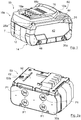
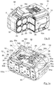
- the figures show embodiments according to the invention of a battery pack for an electric hand tool device, which is generally designated by the reference number 10.
- the first embodiment differs here (as in the Fig. 4 shown) in details relating to the circuit board 24 and its encapsulation from the second embodiment (as in FIGS Figures 7a and 7b shown).
- the housing 10a of a battery pack 10 which is modular in the embodiments shown, is composed of several housing parts forming the housing as follows: a cell carrier 12, two side walls or side parts 14 (see also FIG Figure 2b ), which are detachably attached to the side of the cell carrier 12, as well as at least one housing cover 16 (cf. Fig. 4 ), which can be releasably placed on the cell carrier 12.
- a cell carrier 12 two side walls or side parts 14 (see also FIG Figure 2b ), which are detachably attached to the side of the cell carrier 12, as well as at least one housing cover 16 (cf. Fig. 4 ), which can be releasably placed on the cell carrier 12.
- the side parts 14 and the upper housing cover 16 as detachable housing parts are omitted for better illustration of the internal components of the battery pack 10.
- the cell carrier 12 of the Figures 1 to 7b defines a receiving space 30 for the battery cells 20 to be received and, in the embodiment shown, with a modular housing 10a forms a holding structure for the further housing parts to be attached thereto.
- the housing cover 16 is particularly in the Figures 1 and 6th and comprises at least two ventilation recesses 18a and 18b, via which cooling air from the surroundings of the battery pack 10 can penetrate into the interior of the housing and can be released back into the surroundings.
- the present battery pack 10 is therefore a so-called air-cooled battery pack.
- the present battery pack has a cooling space 12a which is formed in the cell carrier 12.
- the cooling space which is formed separately from the receiving space 30 of the battery cells 20, forms a cooling channel that is closed off from the receiving space 30 and has branches between the layers of several battery cells 20 and opens into slot-shaped ventilation openings 12b, which, when the battery pack 10 is installed, are aligned with the ventilation recesses 18a ( see. Fig. 5 ).
- the battery pack 10 comprises ten battery cells 20 which are arranged essentially parallel to one another. These are arranged in two layers. For example, how to use the Figure 6 can see, a branch of the channel-shaped cooling space 12a extends below the lower layer of the battery cells 20, a branching of the channel-shaped cooling space 12a between the lower layer of the battery cells 20 and the upper layer of the battery cells 20 and a further branch of the channel-shaped cooling space 12a above the upper one Location of the battery cells 20.
- the cell carrier 12 is composed of two essentially mirror-symmetrical holder parts 12c, which are assembled in a dividing plane.
- the cooling channel or channel-shaped cooling space 12a is formed in the area of this dividing plane and is closed in that the two holder parts 12c are connected.
- the dividing plane is the virtual plane that is connected to the circumferential dividing seam T (in Figure 4 ) coincides. In the Figures 5 and 6th a part of a holder part 12c is cut away so that the virtual parting plane can be seen and the interaction of the holder parts 12c can be understood.
- the battery cells 20 are electrically contacted via sheet metal conductors 22 in the region of their poles 20a and 20b, the metal conductor plates 22 in turn being electrically connected to a circuit board 24.
- the circuit board 24 can be equipped with a number of electronic components, which will not be discussed in more detail below.
- the printed circuit board 24 is detachably connected to the cell carrier 12 via screws that are not designated in any more detail.
- the cell carrier 12 For fastening the housing cover 16 and the side part 14, the cell carrier 12 also has fastening projections 26 with threaded recesses 26a, into which fastening screws (not shown) for fastening the housing cover 16 and the side part 14 can be screwed. Furthermore, the cell carrier 12 according to the invention comprises on its upper side 34 facing the printed circuit board at least one recess 28a, which can be used, for example, to introduce a temperature sensor or the like starting from the printed circuit board 24.
- the receiving space 30 delimited on the inside by the cell carrier 12 is provided with the Battery cells (cf. Figure 4 and Figure 6 ) encapsulated with a potting compound 30a (cf. Figure 2a and 3 ).
- the cylindrical battery cells 20 are inserted into the two-part cell carrier 12 and are flush with one another in one plane.
- conductor plates 22 as The battery cells 20 are connected to one another in series or in parallel and connected to the circuit board 24.
- the potting compound 30 is then poured into the receiving space 30 and seals the remaining cavities between the battery cells 20 and the cell carrier 12 in the interior of the receiving space 30.
- the conductor plates 22 are also encapsulated. Only in the area of the positive poles P1 of the battery cells 20 does a recess or cutout remain in order to ensure that the cells in this area, in which an overpressure valve is usually also provided on the cells 20, can outgas in the event of overheating.
- a particularly efficient coating of the battery cells 20 with the potting compound in the area of their outer surfaces in the interior of the cell carrier 12 is also achieved by the fact that the accommodated battery cells are not completely surrounded by the cell carrier 12 in the area of their outer surfaces, but only partially supported by rib-like projections 30b in the Inside the cell carrier 12 (cf. Figure 5 ) are included.
- the cell carrier has bearing sections 32 which are used to store the battery cells 20 are provided with a slight distance from each other.
- the side walls or side parts 14 of the housing of the battery pack 10 are also designed as detachable housing parts.
- the side cover 14 has fastening projections 36 which include bores 36a for receiving a screw.
- the screws (indicated by the reference numeral 46, cf. Fig. 1 ) can be screwed through the bores 36a of the fastening extension 36 into corresponding threaded bores 26a in the area of the fastening sections 26 of the cell carrier 12.
- the side cover 14 has an upper holding edge 38 which, in the assembled state of the battery pack 10, is supported by a corresponding holding edge 50 of the Housing cover 16 can be overlapped (cf. Figure 2b ) and a retaining edge 40, which in turn has a corresponding retaining edge 48 (cf. Figure 1 and Figure 6 ) of the cell carrier 12 is able to reach over in the assembled state of the battery pack 10.
- a circumferential fuse 44 is also provided, which in the assembled state of the associated side part 14 on the cell carrier 12 is able to seal the resulting pole area of the battery pack 10 airtight from the environment.
- This seal 44 can be designed, for example, as an elastomer seal or as a tongue and groove geometry.
- a sealing area 42 is provided in an area of the side parts 14 which, in the assembled state of the battery pack 10, comes into contact with the non-potted poles P1 of the individual battery cells 20.
- these sealing areas 42 are designed in one piece with the associated side part 14 and can also be designed, for example, as an elastomer seal or as a tongue and groove geometry.
- the side part 14 is composed of a soft component and a hard component, the soft component being provided in the sealing area 42 and comprising an elastomer, for example.
- areas with predetermined breaking points are in the area of the side parts 14 54 is provided, the reduced wall thickness of which enables the side part 14 to break through in the event of an overpressure in one of the pole regions P1 and thus an exchange of air into the interior of the housing.
- Sealing areas 42 are provided, it makes sense to assign a predetermined breaking point to each sealing area 42.
- the areas of the predetermined breaking points 54 are additionally surrounded by an annular projection 54a.
- This aspect of the invention is independent of the configuration with the use of one or more potting compounds and the specific configuration of the cell carrier and can assume several functions: on the one hand, these projections 54a are arranged and designed in such a way that the end faces of the cells received in the associated cell carrier 12 Battery cells 20 can come to rest on the annular projections 54a.
- these projections are made of an elastic material, shock absorption of the battery cells 20 is achieved, in particular if, as in the embodiment shown, no shoulder or the like is provided on the associated cell carrier on the receiving areas .
- the battery cells 20 are thus floatingly mounted in the cell carrier 12 in the direction of their longitudinal axis.
- FIG. 2b Another inventive aspect is also in the Figure 2b and relates in particular to battery packs with non-potted conductor plates 22.
- the side covers 14 additionally have separating webs 54b on their inside, which are arranged and aligned in such a way that in the assembled state they protrude between two adjacent assembled conductor plates 22 and separate them from one another.
- the conductor plates 22 have different voltages due to the connection of the battery cells 20, which is why such a separation of the electrical areas is advantageous. In this way, the risk of short circuits as a result of moisture, for example, in the case of non-potted conductor plates 22 can be reduced.
- corresponding intermediate webs can also be provided on the cell carrier, which cooperate with the intermediate webs 54b of the side covers 14 and together form a separating web between the adjacent conductor plates 22.
- separating elements as separating webs
- other design variants are also conceivable, for example as or with projections which, if necessary, interact with corresponding projections on the cell carrier to produce an electrical separation.
- a further receiving area 50 is provided for receiving the printed circuit board 24 with the electronic components.
- this is formed in one piece with the cell carrier 12 on its upper side and is opened in a direction facing away from the battery cells 20 and the associated receiving space 30.
- this second receiving space 50 for receiving the printed circuit board 24 is formed essentially separately from the first receiving space 30 for receiving the battery cells.
- the second receiving space 50 for receiving the circuit board 24 can be encapsulated with a potting compound 52 (cf. Figure 2a ).
- the ventilation openings 12a, 12b are aligned with corresponding openings or recesses 24a. 24b arranged on the printed circuit board 24 and also remain recessed in the potting compound 52 (cf. Figure 2a ).
- the potting compound 52 can be made of an identical material as the first potting compound 30a or a different material. Properties of the casting compound such as thermal conductivity, fire resistance and low inflammability as well as the lowest possible electrical conductivity are advantageous.
- the specific design of the housing of the battery pack according to the invention with a cooling space enclosed in the cell carrier 12 enables, on the one hand, air cooling of the battery cells accommodated therein, as a result of which the service life of the battery pack is significantly increased.
- metallic dust particles and / or air humidity carried along with the cooling air do not get into the area of the battery cells and possibly the electronics and thereby short circuits and in particular damage the battery pack.
- the potting compound used represents an additional measure to protect against metal dust and moisture and also serves to cool the battery pack.
- the cell carrier can also be used for heat dissipation. In this way, a particularly long-lasting and robust battery pack is provided.
- a number of electronic components are applied to the circuit board 24.
- This also includes a charge level indicator for the battery pack, which is generally designated by the reference number 60.
- this comprises four LEDs 64 (indicated in FIG Fig. 4 ), which are fitted on the circuit board 24, as well as a push button switch 62 (indicated in the Fig. 4 ) to operate the charge level indicator 60.
- Four corresponding openings 18a are provided in the housing cover 16, through which, on the one hand, an exchange of air with the surroundings of the battery pack 10 is made possible and, on the other hand, it can be seen from the outside whether the individual LEDs light up or not .
- the charge level indicator can be actuated in a known manner by pressing the pushbutton switch which extends through a further recess on the housing cover 16.
- the charge level indicator 60 is protected from dirt and moisture penetrating from the outside, it can also be partially encapsulated with the further potting compound 52 (as in FIG Fig. 2a shown).
- the further potting compound 52 is made of a light-conducting material so that the LEDs continue to glow from the outside.
- a sealing element 66 is provided, which is placed on the circuit board 24 before the encapsulation with the further encapsulation compound 52 and covers both the pushbutton switch 62 with a corresponding dome 62a and the LEDs laterally sealingly surrounds.
- Special recesses 64a in the sealing element 66 are assigned to the LEDs 64 so that they are not covered by the sealing element 66 and the LEDs 64 remain visible from the outside through the corresponding openings 18a in the housing cover 16.
- the sealing element 66 can be partially covered by the further potting compound 52, in particular in the area of the LEDs, whereby an improved sealing effect can be achieved.
- the dome section 62a which covers the pushbutton switch 62, is greater in its height, ie the extent perpendicular to the circuit board 24, than the further potting compound 52 in order to ensure that it can still be actuated (cf. for example Fig. 2a ).
- the sealing element 66 can in turn be formed from a light-permeable material, so that the recesses 64a can be dispensed with.
- the further sealing compound 52 has a lower height than the sealing element 66 in the region of its lowest height, so that it does not cover the sealing element 66.
- the sealing element 66 seals the pushbutton switch 62 from the outside and the elements of the charge level indicator 60 from the further potting compound 52 (see also FIG Figure 7b ).
- connection blades also known as connection springs or contact springs
- connection blades also known as connection springs or contact springs
- connection springs or contact springs in the Figure 7a five are shown
- the connecting swords 56 overlapped by an electronics cup 70 which has a number of connection slots 72 which are assigned to the respective connection points formed by the connection blades 56.
- a second sealing element 74 is placed on the further potting compound 52. This serves to compensate for play and to allow the electronics cup to sit tightly on the further potting compound 52.
- the second sealing element 74 can in principle also be placed on the circuit board 24 before the encapsulation and encapsulated with the further encapsulation compound 52. In this case it is to choose the height of the second sealing element 74 so that it is greater than the height of the potting compound so that it is not covered by the potting compound and can continue to develop its play-compensating effect.
- the first and the second sealing element 66 and 74 can each be made from an elastic material, for example from foam rubber or the like.
- the cell carrier can have positioning aids that extend outward in a substantially perpendicular direction from the support plane A of the second receiving space 50 for the printed circuit board and serve both to position the printed circuit board and the applied sealing elements can.
- corresponding recesses are provided on the sealing elements 66 and 74.
- FIGS 7a and 7b a further special feature of the present battery pack 10 can be seen in the form of the connecting bridges 80. These serve to connect the conductor plates 22 to the circuit board 24. They have a curved cross section.
- a first end 82 is electrically and mechanically connected to the circuit board 24, for example soldered onto it and / or inserted with a fastening projection 80 a in a form-fitting manner in a corresponding recess on the circuit board 24.
- a second end 84 is provided for connection to a conductor plate 22 and protrudes from the further receiving space 50 in such a way that, in the event of potting with the further potting compound 52, this is not also potted.
- the connecting web 86 between the two ends 82 and 84 is curved and enables the second end to extend out of the further receiving space 50 in the direction of the conductor plate 22 to be connected, as a result of which simple and strand-free contact is achieved.
- the conductor plates 22 can also be electrically connected to the connecting bridges 80 by means of a solder connection. Alternative and additional types of connection that enable electrical contact to be made between the connecting bridges and the conductor plates and / or the circuit board are of course also conceivable.
- Small recesses or receptacles 88 can be provided on the cell carrier 12 in the area of the boundary walls of the further receiving space 50 (cf. Figures 7a, 7b ) through which the connecting bridges 80 can extend. These are also used for the defined attachment of the connecting bridges 80 to the printed circuit board 24. In principle, these can also be dispensed with if the connecting webs 86 are configured accordingly.
- connection plates 90a and 90b form a special form of the connecting bridges, which also enable an electrical connection of the associated conductor plates 22 to the electrical interface of the battery pack 10.
- these have a first end 92a, b and second end 94a, b as well as an associated connecting web 96a, b, which enables electrical contact to be made with the associated conductor plates 22 even after the circuit board 24 has been completely potted.
- connection plate 90a indirectly contacts a first end connection blade 56a of the electrical interface of the battery pack 10 via an interposed first fuse 100a, while the connection plate 90b contacts a second end connection blade 56b indirectly via an interposed second fuse 100b.
- fastening projections 98a, 98b are also provided, which extend in a manner analogous to the fastening projections 80a in the direction of the circuit board 24 and are received in corresponding receptacles on the circuit board 24 for a defined arrangement on the circuit board 24 .
- the connecting bridges and connection plates make it possible to place the circuit board 24 on the cell carrier 12 in the further receiving space 50 at a comparatively early point in time in the assembly process to be attached and to be cast with the further casting compound 52.
- the circuit board 24 is coated with the further potting compound 52 in all areas, except in the area of the pushbutton switch 62 over which the sealing element 66 overlaps.
- electrical contacting of the circuit board for connection to the battery cells would no longer be possible as a result of the coating with the additional potting compound.
- the particularly early fitting of the circuit board to the cell carrier and also early protection of the circuit board by the additional potting compound is very advantageous, since this considerably simplifies handling in the assembly process.
- the early potting enables reliable curing of the further potting compound without further assembly having to be delayed for this.
- the further potting compound 52 not only provides protection for the circuit board 24 against external influences, but also fixes the encapsulated elements attached to the circuit board 24, i.e. the sealing element 66, the connecting bridges 80 and the connection plates 90, by means of a material bond.
- Potting the circuit board with a further potting compound also enables a comparatively simple and inexpensive design of a fuse 100a, 100b. This can also be achieved using a simple sheet metal part.
- the fuses 100a, 100b are formed by a sheet metal part with a first end and a second end, which are each connected to one another by a connecting web.
- the two first ends each serve to make electrical contact with the associated fuse 100a, b with a connection plate 90a, b and the two second ends each serve to make electrical contact with the associated fuse 100a, b with a connecting blade 56a, b of the electrical interface of the battery pack 10.
- the two ends 102 and 104 are also bent over in the manner of the fastening projections 80a, 98a, 98b and engage in corresponding recesses in the circuit board 24 in order to establish a defined arrangement on the circuit board 24 and electrical connection with the ensure the respective connecting parts.
- Alternative types of connection are alternatively or additionally also conceivable.
- the fuses 100a, 100b are also covered at least in sections by the potting compound 52 and secured by this.
- the potting compound 52 can thus replace the function of an additional housing, which is provided as purchased parts in certified fuses. This makes it possible to provide a fuse which is particularly simple and inexpensive to manufacture and which is at the same time just as reliable in its function as the known certified fuses.
- the further potting compound 52 thus not only serves as protection for the printed circuit board 24 in the installed state, but together with the sealing element 66 also enables the pushbutton to be securely sealed, and provides a reliable (cohesive) fixation of the circuit board 24 via a form fit attached connecting bridges, connection plates and fuse parts ready and replaces a fuse housing for the fuses 100a, 100b.
- the cell carrier 12 and the further housing parts 14, 16, 70 are initially formed from, for example, a plastic, for example by means of injection molding. Depending on the design of the side parts 14, for example, several plastic components, for example a hard component and a soft component, can be used in different areas.
- the printed circuit board 24 is equipped with the necessary electronic components and provided with an electrical interface in the form of, for example, connection blades 56 and the necessary recesses.
- the connecting bridges 80, connecting plates 90 and fuses 100 are punched out of sheet metal plates and bent accordingly.
- the circuit board 24 is additionally equipped with the connecting bridges 80, connection plates 90 and fuses 100 and inserted into the further receiving space 50 of the cell carrier 12.
- the sealing elements 66 and 74 are placed on the area of the charge level indicator 60 or the connecting blades 56. If necessary, additional elements are added; For example, a temperature sensor can be provided which is inserted into the receiving space 30 for the battery cells.
- the printed circuit board 24 is completely provided with all the elements to be connected to it, it is cast with the further potting compound 52. This covers almost the entire circuit board 24. Only in the area of the sealing elements 66, 74 do the latter prevent the surface of the circuit board 24 from being wetted with the further potting compound 52.
- the further potting compound 52 can now harden and protect the electronics, so that the pre-assembled assembly of cell carrier 12 and electronics is enabled.
- the cell carrier 12 is equipped with the battery cells. These are connected to the electronics of the circuit board 24 by means of conductor plates via the second ends of the connecting bridges 80 and the connection plates 90.
- the receiving space 30 is then filled with the casting compound and also reliably seals the receiving space 30.
- the other housing parts are attached, i.e. the side parts 14 are attached to the side and the sealing element 74 is placed on the top of the battery in the area of the electrical interface of the battery pack 10 around the connecting blades 56 protruding from the potting compound 52 on the further potting compound 52.
- the electronics cup 70 can then be placed on the sealing element 74 before the housing cover 16 is placed, which at the same time also partially overlaps the side parts 14 and secures them in a form-fitting manner.
- the side parts 14 and the housing cover 16 are releasably fixed to the cell carrier 12 with screws.
Landscapes
- General Chemical & Material Sciences (AREA)
- Chemical & Material Sciences (AREA)
- Chemical Kinetics & Catalysis (AREA)
- Electrochemistry (AREA)
- Engineering & Computer Science (AREA)
- Life Sciences & Earth Sciences (AREA)
- Manufacturing & Machinery (AREA)
- Biophysics (AREA)
- Computer Hardware Design (AREA)
- Microelectronics & Electronic Packaging (AREA)
- Mechanical Engineering (AREA)
- Battery Mounting, Suspending (AREA)
- Secondary Cells (AREA)
Applications Claiming Priority (1)
| Application Number | Priority Date | Filing Date | Title |
|---|---|---|---|
| DE102019119242.0A DE102019119242A1 (de) | 2019-07-16 | 2019-07-16 | Akkupack |
Publications (3)
| Publication Number | Publication Date |
|---|---|
| EP3767732A1 true EP3767732A1 (fr) | 2021-01-20 |
| EP3767732C0 EP3767732C0 (fr) | 2023-12-06 |
| EP3767732B1 EP3767732B1 (fr) | 2023-12-06 |
Family
ID=71620294
Family Applications (2)
| Application Number | Title | Priority Date | Filing Date |
|---|---|---|---|
| EP20185948.5A Active EP3767732B1 (fr) | 2019-07-16 | 2020-07-15 | Bloc-batterie |
| EP20185946.9A Withdrawn EP3767702A1 (fr) | 2019-07-16 | 2020-07-15 | Bloc-batterie |
Family Applications After (1)
| Application Number | Title | Priority Date | Filing Date |
|---|---|---|---|
| EP20185946.9A Withdrawn EP3767702A1 (fr) | 2019-07-16 | 2020-07-15 | Bloc-batterie |
Country Status (2)
| Country | Link |
|---|---|
| EP (2) | EP3767732B1 (fr) |
| DE (1) | DE102019119242A1 (fr) |
Cited By (7)
| Publication number | Priority date | Publication date | Assignee | Title |
|---|---|---|---|---|
| CN115067059A (zh) * | 2021-03-10 | 2022-09-20 | 创科无线普通合伙 | 割草机 |
| WO2022218051A1 (fr) * | 2021-04-15 | 2022-10-20 | 南京泉峰科技有限公司 | Bloc-batterie et outil électrique |
| CN115442999A (zh) * | 2022-08-31 | 2022-12-06 | 深圳市绿联科技股份有限公司 | 一种能源供给设备 |
| EP4113722A3 (fr) * | 2021-06-30 | 2023-04-12 | Robert Bosch GmbH | Bloc d'accumulateur |
| WO2024021064A1 (fr) * | 2022-07-29 | 2024-02-01 | 宁德时代新能源科技股份有限公司 | Batterie et dispositif électrique |
| DE102022213648A1 (de) * | 2022-12-14 | 2024-06-20 | Robert Bosch Gesellschaft mit beschränkter Haftung | Energiespeichereinheit für einen elektrischen Verbraucher |
| EP4645556A4 (fr) * | 2022-12-26 | 2026-04-22 | Panasonic Energy Co Ltd | Bloc-batterie et son procédé de fabrication |
Families Citing this family (3)
| Publication number | Priority date | Publication date | Assignee | Title |
|---|---|---|---|---|
| DE102021111863A1 (de) | 2021-05-06 | 2022-11-10 | instagrid GmbH | Batteriesystem, Batteriemodul und Batteriestring |
| DE102022117987B4 (de) | 2022-07-19 | 2024-11-07 | Metabowerke Gmbh | Akkupack für ein Elektrowerkzeug |
| DE102024106227A1 (de) * | 2024-03-05 | 2025-09-11 | Diehl Metal Applications Gmbh | Akkupack |
Citations (14)
| Publication number | Priority date | Publication date | Assignee | Title |
|---|---|---|---|---|
| EP0940864A2 (fr) * | 1998-03-05 | 1999-09-08 | Black & Decker Inc. | Système de refroidissement pour paquet de batteries |
| DE102004020147A1 (de) | 2004-04-24 | 2005-11-10 | Metabowerke Gmbh | Anordnung umfassend ein Ladegerät und einen Akkupack |
| EP2224513A2 (fr) * | 2009-02-27 | 2010-09-01 | Andreas Stihl AG & Co. KG | Batterie dotée d'un système électronique de surveillance intégré dans un couvercle de boîtier |
| US20140302353A1 (en) | 2013-04-05 | 2014-10-09 | Makita Corporation | Power tool battery pack |
| DE102013211459A1 (de) | 2013-06-19 | 2014-12-24 | Robert Bosch Gmbh | Handwerkzeugmaschinenakkupack |
| US20150194710A1 (en) * | 2014-01-09 | 2015-07-09 | Makita Corporation | Battery packs for electric tools |
| DE102014209444A1 (de) * | 2014-05-19 | 2015-11-19 | Robert Bosch Gmbh | Handwerkzeugmaschinenakkupack |
| US20160013524A1 (en) | 2013-02-26 | 2016-01-14 | Nec Energy Devices, Ltd. | Battery pack |
| US20160240901A1 (en) | 2015-02-13 | 2016-08-18 | Makita Corporation | Battery pack |
| DE202016104759U1 (de) | 2016-07-06 | 2016-09-09 | Astrit Hajzeraj | Batterie und Verbindungsplatte für eine Batterie |
| DE102015110308A1 (de) | 2015-03-09 | 2016-09-15 | Metabowerke Gmbh | Akkupack für ein Elektrohandwerkzeuggerät |
| DE102017109919A1 (de) | 2017-05-09 | 2018-11-15 | C. & E. Fein Gmbh | Akkumulatorpaket |
| DE102018104342B3 (de) * | 2018-02-26 | 2019-07-04 | Metabowerke Gmbh | Akkupack sowie Elektrohandwerkzeuggerät |
| DE102018104337A1 (de) | 2018-02-26 | 2019-08-29 | Metabowerke Gmbh | Akkupack sowie Elektrohandwerkzeuggerät |
Family Cites Families (3)
| Publication number | Priority date | Publication date | Assignee | Title |
|---|---|---|---|---|
| JP3805664B2 (ja) * | 2001-11-01 | 2006-08-02 | 株式会社マキタ | 電池パック |
| DE102010032936B4 (de) * | 2010-07-30 | 2022-05-25 | Sew-Eurodrive Gmbh & Co Kg | Anordnung zum Kühlen von Wärme erzeugenden elektrischen Bauelementen, Kondensatorbaugruppe und Herstellverfahren für eine Anordnung |
| CN204424329U (zh) * | 2011-12-30 | 2015-06-24 | 株式会社牧田 | 适于与手持式电动工具一起使用的电池组 |
-
2019
- 2019-07-16 DE DE102019119242.0A patent/DE102019119242A1/de not_active Withdrawn
-
2020
- 2020-07-15 EP EP20185948.5A patent/EP3767732B1/fr active Active
- 2020-07-15 EP EP20185946.9A patent/EP3767702A1/fr not_active Withdrawn
Patent Citations (15)
| Publication number | Priority date | Publication date | Assignee | Title |
|---|---|---|---|---|
| EP0940864A2 (fr) * | 1998-03-05 | 1999-09-08 | Black & Decker Inc. | Système de refroidissement pour paquet de batteries |
| DE102004020147A1 (de) | 2004-04-24 | 2005-11-10 | Metabowerke Gmbh | Anordnung umfassend ein Ladegerät und einen Akkupack |
| EP2224513A2 (fr) * | 2009-02-27 | 2010-09-01 | Andreas Stihl AG & Co. KG | Batterie dotée d'un système électronique de surveillance intégré dans un couvercle de boîtier |
| DE102009012176A1 (de) | 2009-02-27 | 2010-09-02 | Andreas Stihl Ag & Co. Kg | Akkupack mit im Gehäusedeckel integrierter Überwachungselektronik |
| US20160013524A1 (en) | 2013-02-26 | 2016-01-14 | Nec Energy Devices, Ltd. | Battery pack |
| US20140302353A1 (en) | 2013-04-05 | 2014-10-09 | Makita Corporation | Power tool battery pack |
| DE102013211459A1 (de) | 2013-06-19 | 2014-12-24 | Robert Bosch Gmbh | Handwerkzeugmaschinenakkupack |
| US20150194710A1 (en) * | 2014-01-09 | 2015-07-09 | Makita Corporation | Battery packs for electric tools |
| DE102014209444A1 (de) * | 2014-05-19 | 2015-11-19 | Robert Bosch Gmbh | Handwerkzeugmaschinenakkupack |
| US20160240901A1 (en) | 2015-02-13 | 2016-08-18 | Makita Corporation | Battery pack |
| DE102015110308A1 (de) | 2015-03-09 | 2016-09-15 | Metabowerke Gmbh | Akkupack für ein Elektrohandwerkzeuggerät |
| DE202016104759U1 (de) | 2016-07-06 | 2016-09-09 | Astrit Hajzeraj | Batterie und Verbindungsplatte für eine Batterie |
| DE102017109919A1 (de) | 2017-05-09 | 2018-11-15 | C. & E. Fein Gmbh | Akkumulatorpaket |
| DE102018104342B3 (de) * | 2018-02-26 | 2019-07-04 | Metabowerke Gmbh | Akkupack sowie Elektrohandwerkzeuggerät |
| DE102018104337A1 (de) | 2018-02-26 | 2019-08-29 | Metabowerke Gmbh | Akkupack sowie Elektrohandwerkzeuggerät |
Cited By (8)
| Publication number | Priority date | Publication date | Assignee | Title |
|---|---|---|---|---|
| CN115067059A (zh) * | 2021-03-10 | 2022-09-20 | 创科无线普通合伙 | 割草机 |
| WO2022218051A1 (fr) * | 2021-04-15 | 2022-10-20 | 南京泉峰科技有限公司 | Bloc-batterie et outil électrique |
| EP4113722A3 (fr) * | 2021-06-30 | 2023-04-12 | Robert Bosch GmbH | Bloc d'accumulateur |
| US12614806B2 (en) | 2021-06-30 | 2026-04-28 | Robert Bosch Gmbh | Battery pack including a circuit board mounted to a housing |
| WO2024021064A1 (fr) * | 2022-07-29 | 2024-02-01 | 宁德时代新能源科技股份有限公司 | Batterie et dispositif électrique |
| CN115442999A (zh) * | 2022-08-31 | 2022-12-06 | 深圳市绿联科技股份有限公司 | 一种能源供给设备 |
| DE102022213648A1 (de) * | 2022-12-14 | 2024-06-20 | Robert Bosch Gesellschaft mit beschränkter Haftung | Energiespeichereinheit für einen elektrischen Verbraucher |
| EP4645556A4 (fr) * | 2022-12-26 | 2026-04-22 | Panasonic Energy Co Ltd | Bloc-batterie et son procédé de fabrication |
Also Published As
| Publication number | Publication date |
|---|---|
| DE102019119242A1 (de) | 2021-01-21 |
| EP3767732C0 (fr) | 2023-12-06 |
| EP3767702A1 (fr) | 2021-01-20 |
| EP3767732B1 (fr) | 2023-12-06 |
Similar Documents
| Publication | Publication Date | Title |
|---|---|---|
| EP3767732B1 (fr) | Bloc-batterie | |
| DE102019201986B4 (de) | Batteriegehäuse zur Aufnahme wenigstens eines Zellmoduls einer Traktionsbatterie | |
| DE102008059960B4 (de) | Verfahren zur Herstellung einer Batterie, nach dem Verfahren hergestellte Batterie und Batterieverbund aus zwei derartigen Batterien | |
| WO2010040520A2 (fr) | Batterie lithium-ion | |
| EP3531470B1 (fr) | Bloc d'accumulateur et appareil d'outil électrique | |
| DE102008059956A1 (de) | Batterie, insbesondere Fahrzeugbatterie | |
| EP3531472B1 (fr) | Bloc d'accumulateur et appareil d'outil électrique | |
| EP2721662B1 (fr) | Batterie pour vehicule | |
| DE102014203715A1 (de) | Effizient kühlbares Gehäuse für ein Batteriemodul | |
| DE69003679T2 (de) | Umschaltbares doppelbatteriesystem. | |
| EP3531468B1 (fr) | Bloc d'accumulateur et appareil d'outil électrique | |
| EP4309232A1 (fr) | Dispositif de refroidissement comprenant un dissipateur thermique et des éléments de refroidissement intermédiaires, accumulateur d'énergie électrique et véhicule automobile | |
| WO2022157115A1 (fr) | Système de stockage d'énergie et véhicule à moteur | |
| DE102018214543A1 (de) | Batteriezelle mit integrierter Kühlung und Batteriemodul für ein Kraftfahrzeug mit mehreren Batteriezellen | |
| DE102012224330A1 (de) | Elektrische Akkumulatorvorrichtung mit elastischen Elementen | |
| DE102020109105A1 (de) | Akkupack für ein Elektrogerät | |
| EP3531469A1 (fr) | Bloc d'accumulateur ainsi qu'appareil-outil portatif électrique | |
| DE102013218531B4 (de) | Akkuvorrichtung | |
| EP3531473B1 (fr) | Bloc-accumulateur ainsi qu'appareil outil portatif électrique et son procédé de fabrication | |
| EP2465151A1 (fr) | Procédé de fabrication d'un dispositif accumulateur d'énergie pour un véhicule | |
| WO2013000617A1 (fr) | Élément de contact destiné à la mise en contact mécanique, thermique et électrique d'un accumulateur d'énergie | |
| EP1894265B1 (fr) | Pontet de connexion destine a une batterie | |
| DE102022213649A1 (de) | Energiespeichereinheit für einen elektrischen Verbraucher | |
| DE102008059957A1 (de) | Batterie mit wenigstens einer Batteriezelle | |
| DE102022117987B4 (de) | Akkupack für ein Elektrowerkzeug |
Legal Events
| Date | Code | Title | Description |
|---|---|---|---|
| PUAI | Public reference made under article 153(3) epc to a published international application that has entered the european phase |
Free format text: ORIGINAL CODE: 0009012 |
|
| STAA | Information on the status of an ep patent application or granted ep patent |
Free format text: STATUS: THE APPLICATION HAS BEEN PUBLISHED |
|
| AK | Designated contracting states |
Kind code of ref document: A1 Designated state(s): AL AT BE BG CH CY CZ DE DK EE ES FI FR GB GR HR HU IE IS IT LI LT LU LV MC MK MT NL NO PL PT RO RS SE SI SK SM TR |
|
| AX | Request for extension of the european patent |
Extension state: BA ME |
|
| STAA | Information on the status of an ep patent application or granted ep patent |
Free format text: STATUS: REQUEST FOR EXAMINATION WAS MADE |
|
| 17P | Request for examination filed |
Effective date: 20210719 |
|
| RBV | Designated contracting states (corrected) |
Designated state(s): AL AT BE BG CH CY CZ DE DK EE ES FI FR GB GR HR HU IE IS IT LI LT LU LV MC MK MT NL NO PL PT RO RS SE SI SK SM TR |
|
| REG | Reference to a national code |
Ref legal event code: R079 Ipc: H01M0050213000 Ref country code: DE Ref legal event code: R079 Ref document number: 502020006265 Country of ref document: DE Free format text: PREVIOUS MAIN CLASS: H01M0010420000 Ipc: H01M0050213000 |
|
| GRAP | Despatch of communication of intention to grant a patent |
Free format text: ORIGINAL CODE: EPIDOSNIGR1 |
|
| STAA | Information on the status of an ep patent application or granted ep patent |
Free format text: STATUS: GRANT OF PATENT IS INTENDED |
|
| RIC1 | Information provided on ipc code assigned before grant |
Ipc: H01M 50/247 20210101ALI20230605BHEP Ipc: B25F 5/00 20060101ALI20230605BHEP Ipc: H01M 50/24 20210101ALI20230605BHEP Ipc: H01M 10/42 20060101ALI20230605BHEP Ipc: H01M 50/213 20210101AFI20230605BHEP |
|
| INTG | Intention to grant announced |
Effective date: 20230626 |
|
| GRAS | Grant fee paid |
Free format text: ORIGINAL CODE: EPIDOSNIGR3 |
|
| GRAA | (expected) grant |
Free format text: ORIGINAL CODE: 0009210 |
|
| STAA | Information on the status of an ep patent application or granted ep patent |
Free format text: STATUS: THE PATENT HAS BEEN GRANTED |
|
| AK | Designated contracting states |
Kind code of ref document: B1 Designated state(s): AL AT BE BG CH CY CZ DE DK EE ES FI FR GB GR HR HU IE IS IT LI LT LU LV MC MK MT NL NO PL PT RO RS SE SI SK SM TR |
|
| REG | Reference to a national code |
Ref country code: GB Ref legal event code: FG4D Free format text: NOT ENGLISH |
|
| REG | Reference to a national code |
Ref country code: CH Ref legal event code: EP |
|
| REG | Reference to a national code |
Ref country code: DE Ref legal event code: R096 Ref document number: 502020006265 Country of ref document: DE |
|
| REG | Reference to a national code |
Ref country code: IE Ref legal event code: FG4D Free format text: LANGUAGE OF EP DOCUMENT: GERMAN |
|
| U01 | Request for unitary effect filed |
Effective date: 20231211 |
|
| U07 | Unitary effect registered |
Designated state(s): AT BE BG DE DK EE FI FR IT LT LU LV MT NL PT SE SI Effective date: 20231218 |
|
| PG25 | Lapsed in a contracting state [announced via postgrant information from national office to epo] |
Ref country code: GR Free format text: LAPSE BECAUSE OF FAILURE TO SUBMIT A TRANSLATION OF THE DESCRIPTION OR TO PAY THE FEE WITHIN THE PRESCRIBED TIME-LIMIT Effective date: 20240307 |
|
| PG25 | Lapsed in a contracting state [announced via postgrant information from national office to epo] |
Ref country code: ES Free format text: LAPSE BECAUSE OF FAILURE TO SUBMIT A TRANSLATION OF THE DESCRIPTION OR TO PAY THE FEE WITHIN THE PRESCRIBED TIME-LIMIT Effective date: 20231206 |
|
| PG25 | Lapsed in a contracting state [announced via postgrant information from national office to epo] |
Ref country code: GR Free format text: LAPSE BECAUSE OF FAILURE TO SUBMIT A TRANSLATION OF THE DESCRIPTION OR TO PAY THE FEE WITHIN THE PRESCRIBED TIME-LIMIT Effective date: 20240307 Ref country code: ES Free format text: LAPSE BECAUSE OF FAILURE TO SUBMIT A TRANSLATION OF THE DESCRIPTION OR TO PAY THE FEE WITHIN THE PRESCRIBED TIME-LIMIT Effective date: 20231206 |
|
| PG25 | Lapsed in a contracting state [announced via postgrant information from national office to epo] |
Ref country code: RS Free format text: LAPSE BECAUSE OF FAILURE TO SUBMIT A TRANSLATION OF THE DESCRIPTION OR TO PAY THE FEE WITHIN THE PRESCRIBED TIME-LIMIT Effective date: 20231206 Ref country code: NO Free format text: LAPSE BECAUSE OF FAILURE TO SUBMIT A TRANSLATION OF THE DESCRIPTION OR TO PAY THE FEE WITHIN THE PRESCRIBED TIME-LIMIT Effective date: 20240306 Ref country code: HR Free format text: LAPSE BECAUSE OF FAILURE TO SUBMIT A TRANSLATION OF THE DESCRIPTION OR TO PAY THE FEE WITHIN THE PRESCRIBED TIME-LIMIT Effective date: 20231206 |
|
| PG25 | Lapsed in a contracting state [announced via postgrant information from national office to epo] |
Ref country code: IS Free format text: LAPSE BECAUSE OF FAILURE TO SUBMIT A TRANSLATION OF THE DESCRIPTION OR TO PAY THE FEE WITHIN THE PRESCRIBED TIME-LIMIT Effective date: 20240406 |
|
| PG25 | Lapsed in a contracting state [announced via postgrant information from national office to epo] |
Ref country code: CZ Free format text: LAPSE BECAUSE OF FAILURE TO SUBMIT A TRANSLATION OF THE DESCRIPTION OR TO PAY THE FEE WITHIN THE PRESCRIBED TIME-LIMIT Effective date: 20231206 |
|
| PG25 | Lapsed in a contracting state [announced via postgrant information from national office to epo] |
Ref country code: SK Free format text: LAPSE BECAUSE OF FAILURE TO SUBMIT A TRANSLATION OF THE DESCRIPTION OR TO PAY THE FEE WITHIN THE PRESCRIBED TIME-LIMIT Effective date: 20231206 |
|
| PG25 | Lapsed in a contracting state [announced via postgrant information from national office to epo] |
Ref country code: SM Free format text: LAPSE BECAUSE OF FAILURE TO SUBMIT A TRANSLATION OF THE DESCRIPTION OR TO PAY THE FEE WITHIN THE PRESCRIBED TIME-LIMIT Effective date: 20231206 Ref country code: SK Free format text: LAPSE BECAUSE OF FAILURE TO SUBMIT A TRANSLATION OF THE DESCRIPTION OR TO PAY THE FEE WITHIN THE PRESCRIBED TIME-LIMIT Effective date: 20231206 Ref country code: RO Free format text: LAPSE BECAUSE OF FAILURE TO SUBMIT A TRANSLATION OF THE DESCRIPTION OR TO PAY THE FEE WITHIN THE PRESCRIBED TIME-LIMIT Effective date: 20231206 Ref country code: IS Free format text: LAPSE BECAUSE OF FAILURE TO SUBMIT A TRANSLATION OF THE DESCRIPTION OR TO PAY THE FEE WITHIN THE PRESCRIBED TIME-LIMIT Effective date: 20240406 Ref country code: CZ Free format text: LAPSE BECAUSE OF FAILURE TO SUBMIT A TRANSLATION OF THE DESCRIPTION OR TO PAY THE FEE WITHIN THE PRESCRIBED TIME-LIMIT Effective date: 20231206 |
|
| PG25 | Lapsed in a contracting state [announced via postgrant information from national office to epo] |
Ref country code: PL Free format text: LAPSE BECAUSE OF FAILURE TO SUBMIT A TRANSLATION OF THE DESCRIPTION OR TO PAY THE FEE WITHIN THE PRESCRIBED TIME-LIMIT Effective date: 20231206 |
|
| U20 | Renewal fee for the european patent with unitary effect paid |
Year of fee payment: 5 Effective date: 20240717 |
|
| PG25 | Lapsed in a contracting state [announced via postgrant information from national office to epo] |
Ref country code: PL Free format text: LAPSE BECAUSE OF FAILURE TO SUBMIT A TRANSLATION OF THE DESCRIPTION OR TO PAY THE FEE WITHIN THE PRESCRIBED TIME-LIMIT Effective date: 20231206 |
|
| REG | Reference to a national code |
Ref country code: DE Ref legal event code: R097 Ref document number: 502020006265 Country of ref document: DE |
|
| PLBE | No opposition filed within time limit |
Free format text: ORIGINAL CODE: 0009261 |
|
| STAA | Information on the status of an ep patent application or granted ep patent |
Free format text: STATUS: NO OPPOSITION FILED WITHIN TIME LIMIT |
|
| 26N | No opposition filed |
Effective date: 20240909 |
|
| PG25 | Lapsed in a contracting state [announced via postgrant information from national office to epo] |
Ref country code: MC Free format text: LAPSE BECAUSE OF FAILURE TO SUBMIT A TRANSLATION OF THE DESCRIPTION OR TO PAY THE FEE WITHIN THE PRESCRIBED TIME-LIMIT Effective date: 20231206 |
|
| REG | Reference to a national code |
Ref country code: CH Ref legal event code: PL |
|
| GBPC | Gb: european patent ceased through non-payment of renewal fee |
Effective date: 20240715 |
|
| PG25 | Lapsed in a contracting state [announced via postgrant information from national office to epo] |
Ref country code: CH Free format text: LAPSE BECAUSE OF NON-PAYMENT OF DUE FEES Effective date: 20240731 |
|
| PG25 | Lapsed in a contracting state [announced via postgrant information from national office to epo] |
Ref country code: GB Free format text: LAPSE BECAUSE OF NON-PAYMENT OF DUE FEES Effective date: 20240715 |
|
| PG25 | Lapsed in a contracting state [announced via postgrant information from national office to epo] |
Ref country code: IE Free format text: LAPSE BECAUSE OF NON-PAYMENT OF DUE FEES Effective date: 20240715 |
|
| U20 | Renewal fee for the european patent with unitary effect paid |
Year of fee payment: 6 Effective date: 20250729 |
|
| PG25 | Lapsed in a contracting state [announced via postgrant information from national office to epo] |
Ref country code: CY Free format text: LAPSE BECAUSE OF FAILURE TO SUBMIT A TRANSLATION OF THE DESCRIPTION OR TO PAY THE FEE WITHIN THE PRESCRIBED TIME-LIMIT; INVALID AB INITIO Effective date: 20200715 |
|
| PG25 | Lapsed in a contracting state [announced via postgrant information from national office to epo] |
Ref country code: HU Free format text: LAPSE BECAUSE OF FAILURE TO SUBMIT A TRANSLATION OF THE DESCRIPTION OR TO PAY THE FEE WITHIN THE PRESCRIBED TIME-LIMIT; INVALID AB INITIO Effective date: 20200715 |