EP3767787B1 - Système d'alimentation électrique, dispositif convertisseur cc-cc et procédé de chargement - Google Patents
Système d'alimentation électrique, dispositif convertisseur cc-cc et procédé de chargement Download PDFInfo
- Publication number
- EP3767787B1 EP3767787B1 EP20185668.9A EP20185668A EP3767787B1 EP 3767787 B1 EP3767787 B1 EP 3767787B1 EP 20185668 A EP20185668 A EP 20185668A EP 3767787 B1 EP3767787 B1 EP 3767787B1
- Authority
- EP
- European Patent Office
- Prior art keywords
- low voltage
- dcdc converter
- battery
- voltage
- power supply
- Prior art date
- Legal status (The legal status is an assumption and is not a legal conclusion. Google has not performed a legal analysis and makes no representation as to the accuracy of the status listed.)
- Active
Links
Images




Classifications
-
- H—ELECTRICITY
- H02—GENERATION; CONVERSION OR DISTRIBUTION OF ELECTRIC POWER
- H02J—ELECTRIC POWER NETWORKS; CIRCUIT ARRANGEMENTS OR SYSTEMS FOR SUPPLYING OR DISTRIBUTING ELECTRIC POWER; SYSTEMS FOR STORING ELECTRIC ENERGY
- H02J7/00—Circuit arrangements for charging or discharging batteries or for supplying loads from batteries
- H02J7/14—Circuit arrangements for charging or discharging batteries or for supplying loads from batteries for charging batteries from dynamo-electric generators driven at varying speed, e.g. on vehicle
-
- B—PERFORMING OPERATIONS; TRANSPORTING
- B60—VEHICLES IN GENERAL
- B60L—PROPULSION OF ELECTRICALLY-PROPELLED VEHICLES; SUPPLYING ELECTRIC POWER FOR AUXILIARY EQUIPMENT OF ELECTRICALLY-PROPELLED VEHICLES; ELECTRODYNAMIC BRAKE SYSTEMS FOR VEHICLES IN GENERAL; MAGNETIC SUSPENSION OR LEVITATION FOR VEHICLES; MONITORING OPERATING VARIABLES OF ELECTRICALLY-PROPELLED VEHICLES; ELECTRIC SAFETY DEVICES FOR ELECTRICALLY-PROPELLED VEHICLES
- B60L58/00—Methods or circuit arrangements for monitoring or controlling batteries or fuel cells, specially adapted for electric vehicles
- B60L58/10—Methods or circuit arrangements for monitoring or controlling batteries or fuel cells, specially adapted for electric vehicles for monitoring or controlling batteries
- B60L58/18—Methods or circuit arrangements for monitoring or controlling batteries or fuel cells, specially adapted for electric vehicles for monitoring or controlling batteries of two or more battery modules
- B60L58/20—Methods or circuit arrangements for monitoring or controlling batteries or fuel cells, specially adapted for electric vehicles for monitoring or controlling batteries of two or more battery modules having different nominal voltages
-
- B—PERFORMING OPERATIONS; TRANSPORTING
- B60—VEHICLES IN GENERAL
- B60L—PROPULSION OF ELECTRICALLY-PROPELLED VEHICLES; SUPPLYING ELECTRIC POWER FOR AUXILIARY EQUIPMENT OF ELECTRICALLY-PROPELLED VEHICLES; ELECTRODYNAMIC BRAKE SYSTEMS FOR VEHICLES IN GENERAL; MAGNETIC SUSPENSION OR LEVITATION FOR VEHICLES; MONITORING OPERATING VARIABLES OF ELECTRICALLY-PROPELLED VEHICLES; ELECTRIC SAFETY DEVICES FOR ELECTRICALLY-PROPELLED VEHICLES
- B60L58/00—Methods or circuit arrangements for monitoring or controlling batteries or fuel cells, specially adapted for electric vehicles
- B60L58/10—Methods or circuit arrangements for monitoring or controlling batteries or fuel cells, specially adapted for electric vehicles for monitoring or controlling batteries
- B60L58/18—Methods or circuit arrangements for monitoring or controlling batteries or fuel cells, specially adapted for electric vehicles for monitoring or controlling batteries of two or more battery modules
- B60L58/21—Methods or circuit arrangements for monitoring or controlling batteries or fuel cells, specially adapted for electric vehicles for monitoring or controlling batteries of two or more battery modules having the same nominal voltage
-
- B—PERFORMING OPERATIONS; TRANSPORTING
- B60—VEHICLES IN GENERAL
- B60R—VEHICLES, VEHICLE FITTINGS, OR VEHICLE PARTS, NOT OTHERWISE PROVIDED FOR
- B60R16/00—Electric or fluid circuits specially adapted for vehicles and not otherwise provided for; Arrangement of elements of electric or fluid circuits specially adapted for vehicles and not otherwise provided for
- B60R16/02—Electric or fluid circuits specially adapted for vehicles and not otherwise provided for; Arrangement of elements of electric or fluid circuits specially adapted for vehicles and not otherwise provided for electric constitutive elements
- B60R16/03—Electric or fluid circuits specially adapted for vehicles and not otherwise provided for; Arrangement of elements of electric or fluid circuits specially adapted for vehicles and not otherwise provided for electric constitutive elements for supply of electrical power to vehicle subsystems or for
- B60R16/033—Electric or fluid circuits specially adapted for vehicles and not otherwise provided for; Arrangement of elements of electric or fluid circuits specially adapted for vehicles and not otherwise provided for electric constitutive elements for supply of electrical power to vehicle subsystems or for characterised by the use of electrical cells or batteries
-
- H—ELECTRICITY
- H02—GENERATION; CONVERSION OR DISTRIBUTION OF ELECTRIC POWER
- H02J—ELECTRIC POWER NETWORKS; CIRCUIT ARRANGEMENTS OR SYSTEMS FOR SUPPLYING OR DISTRIBUTING ELECTRIC POWER; SYSTEMS FOR STORING ELECTRIC ENERGY
- H02J7/00—Circuit arrangements for charging or discharging batteries or for supplying loads from batteries
- H02J7/34—Parallel operation in networks using both storage and other DC sources, e.g. providing buffering
- H02J7/342—The other DC source being a battery actively interacting with the first one, i.e. battery to battery charging
-
- H—ELECTRICITY
- H02—GENERATION; CONVERSION OR DISTRIBUTION OF ELECTRIC POWER
- H02J—ELECTRIC POWER NETWORKS; CIRCUIT ARRANGEMENTS OR SYSTEMS FOR SUPPLYING OR DISTRIBUTING ELECTRIC POWER; SYSTEMS FOR STORING ELECTRIC ENERGY
- H02J7/00—Circuit arrangements for charging or discharging batteries or for supplying loads from batteries
- H02J7/485—Circuit arrangements for charging or discharging batteries or for supplying loads from batteries with provisions for charging different types of batteries
-
- H—ELECTRICITY
- H02—GENERATION; CONVERSION OR DISTRIBUTION OF ELECTRIC POWER
- H02J—ELECTRIC POWER NETWORKS; CIRCUIT ARRANGEMENTS OR SYSTEMS FOR SUPPLYING OR DISTRIBUTING ELECTRIC POWER; SYSTEMS FOR STORING ELECTRIC ENERGY
- H02J7/00—Circuit arrangements for charging or discharging batteries or for supplying loads from batteries
- H02J7/50—Circuit arrangements for charging or discharging batteries or for supplying loads from batteries acting upon multiple batteries simultaneously or sequentially
-
- H—ELECTRICITY
- H02—GENERATION; CONVERSION OR DISTRIBUTION OF ELECTRIC POWER
- H02J—ELECTRIC POWER NETWORKS; CIRCUIT ARRANGEMENTS OR SYSTEMS FOR SUPPLYING OR DISTRIBUTING ELECTRIC POWER; SYSTEMS FOR STORING ELECTRIC ENERGY
- H02J7/00—Circuit arrangements for charging or discharging batteries or for supplying loads from batteries
- H02J7/80—Circuit arrangements for charging or discharging batteries or for supplying loads from batteries including monitoring or indicating arrangements
- H02J7/82—Control of state of charge [SOC]
-
- H—ELECTRICITY
- H02—GENERATION; CONVERSION OR DISTRIBUTION OF ELECTRIC POWER
- H02J—ELECTRIC POWER NETWORKS; CIRCUIT ARRANGEMENTS OR SYSTEMS FOR SUPPLYING OR DISTRIBUTING ELECTRIC POWER; SYSTEMS FOR STORING ELECTRIC ENERGY
- H02J7/00—Circuit arrangements for charging or discharging batteries or for supplying loads from batteries
- H02J7/855—Circuit arrangements for charging or discharging batteries or for supplying loads from batteries with circuits adapted for supplying loads from the battery
-
- H—ELECTRICITY
- H02—GENERATION; CONVERSION OR DISTRIBUTION OF ELECTRIC POWER
- H02J—ELECTRIC POWER NETWORKS; CIRCUIT ARRANGEMENTS OR SYSTEMS FOR SUPPLYING OR DISTRIBUTING ELECTRIC POWER; SYSTEMS FOR STORING ELECTRIC ENERGY
- H02J7/00—Circuit arrangements for charging or discharging batteries or for supplying loads from batteries
- H02J7/90—Regulation of charging or discharging current or voltage
- H02J7/96—Regulation of charging or discharging current or voltage in response to battery voltage
-
- H—ELECTRICITY
- H02—GENERATION; CONVERSION OR DISTRIBUTION OF ELECTRIC POWER
- H02J—ELECTRIC POWER NETWORKS; CIRCUIT ARRANGEMENTS OR SYSTEMS FOR SUPPLYING OR DISTRIBUTING ELECTRIC POWER; SYSTEMS FOR STORING ELECTRIC ENERGY
- H02J2207/00—Details of circuit arrangements for charging or discharging batteries or supplying loads from batteries
- H02J2207/20—Charging or discharging characterised by the power electronics converter
Definitions
- a bypass circuit can also be used as the circuit in which a dark current flows, the number of circuits does not increase, which can consequently contribute to miniaturization of the power supply system.
- control device may include a switch control unit configured to control on/off of the switch unit based on a state of charge of the low voltage lithium battery.
- the switch unit of the bypass circuit is turned on/off based on the state of charge (SOC) of the low voltage lithium battery, if the switch unit is turned off when the state of charge is low, a current flows to the second DCDC converter side in the circuit, and constant current charging can be performed by using the second DCDC converter. Then, if the switch unit is turned on when the state of charge escapes from the state in which the state of charge is low, a current flows to the bypass circuit side in the circuit, and constant voltage charging can be performed at a charging voltage to the low voltage lead battery by the first DCDC converter.
- SOC state of charge
- control device may include a switch control unit configured to control on/off of the switch unit based on a voltage and a predetermined voltage range of the low voltage lithium battery.
- the switch unit of the bypass circuit is turned on/off based on the a voltage and a predetermined voltage range of the low voltage lithium battery, if the switch unit is turned on when the voltage of the low voltage lithium battery is within the predetermined voltage range, a current can flow to the bypass circuit side. Then, constant voltage charging can be performed on the low voltage lithium battery by the charging voltage from the first DCDC converter to the low voltage lead battery.
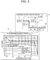
- the low voltage lead battery 7 is a so-called lead storage battery (secondary battery) and is connected to the low voltage power supply circuit 6. As shown in graphs of Fig. 2 to Fig. 4 , the low voltage lead battery 7 has characteristics (capacity characteristics of a lead battery) serving as a downward-sloping solid line. The low voltage lead battery 7 is charged with step-down electric power from the first DCDC converter 5. In the low voltage lead battery 7, the voltage is watched by the control device 11.
- the first load 8 is equipment that operates with low voltage electric power to be supplied from the low voltage lead battery 7, such as a combination meter. Further, the first load 8 include an electronic control unit including the control device 11. The control device 11 will be described later.
- the number of internal FETs can be reduced compared with a case where electric power always flows. Accordingly, capacity of the second DCDC converter 12 can be reduced. Due to the second DCDC converter 2 including the bypass circuit 13, electric power does not always flow to the second DCDC converter 12.
- the bypass circuit 13 is connected to the low voltage power supply circuit 6 and is configured to bypass the second DCDC converter 12. Further, the bypass circuit 13 is configured such that the electric power from the low voltage battery 7 can flow to the low voltage lithium battery 9 without passing through the second DCDC converter 12.
- the bypass circuit 13 is also used as a circuit in which a dark current flows (an example, but a preferred form).
- a switch unit 14 is disposed on such a way of the bypass circuit 13. In the present embodiment, an FET is employed as the switch unit 14. The on/off of the switch unit 14 is controlled by the control device 11. When the switch unit 14 is turned on under control of the control device 11, the electric power from the low voltage lead battery 7 is bypassed, and as a result, the low voltage lithium battery 9 is charged with a charging voltage of the low voltage lead battery 7.
- the low voltage lithium battery 9 is a publicly known lithium ion battery and is configured for low voltage.
- the low voltage lithium battery 9 is provided to operate the second load 10 connected to the downstream.
- the low voltage lithium battery 9 has a characteristic as a thick solid line having two bends and downward-sloping dots.
- the low voltage lithium battery 9 is charged with the electric power from the second DCDC converter 12 or the electric power that bypasses the second DCDC converter 12.
- the low voltage lithium battery 9 is watched by the control device 11. Specifically, the voltage of the low voltage lithium battery 9 is watched by the control device 11.
- the second load 10 is equipment that operates with low voltage electric power to be supplied from the low voltage lithium battery 9.
- An electronic control unit including the control device 11 may be used as the second load 10.
- the control device 11 has a function for, for example, battery management.
- the control device 11 is provided with a microcomputer (CPU), a storage device, and the like.
- the control device 11 is provided with the switch control unit 15 that controls on/off of the switch unit 14.
- the switch control unit 15 is configured to be able to control on/off of the switch unit 14 based on a state of charge (SOC) of the low voltage lithium battery 9.
- SOC state of charge
- the switch control unit 15 is configured to be able to control on/off of the switch unit 14 based on a charging voltage of the low voltage lithium battery 7 due to the first DCDC converter 5.
- the configuration may be based on the voltage of the low voltage lithium battery 9 and a predetermined voltage range W (see Fig. 2 ) not limited to such on/off control.
- a region is controlled to be constant voltage charging.
- the switch unit 14 is in an off state, and constant voltage charging is performed by using the second DCDC converter 12.
- the voltage is slightly stepped up to the electric power input from the low voltage lead battery 7, and then the low voltage lithium battery 9 is charged with a constant voltage.
- the switch unit 14 may be in an off state depending on whether the voltage is in a range of the predetermined voltage range W. In the region of Fig.
- the second DCDC converter 12 is used, but since 12 V added by a few volts has already been charged, the voltage does not need to be stepped up rapidly. Therefore, the number of FETs provided inside the second DCDC converter 12 may be reduced. Accordingly, the capacity of the second DCDC converter 12 can be reduced.
- step S4 When the voltage needs to be slightly stepped up (Y in step S4), the process shifts to step S5, and constant voltage charging is performed after slightly stepping up the voltage.
- step S6 and step S7 are executed in order.
- step S6 the switch unit 14 (FET) of the bypass circuit 13 is turned on.
- step S7 charging (constant voltage charging) is performed at a charging voltage of the low voltage lead battery 7.
- step S11 when an ignition switch (IG) of a vehicle is turned on, step S11 is executed in the control device 11.
- the switch unit 14 (FET) of the bypass circuit 13 is turned off by step S11.
- step S12 is executed, and it is determined whether the voltage of the low voltage lithium battery 9 is within the range of the predetermined voltage range W.
- step S13 and step S14 are executed in order.
- step S13 the switch unit 14 (FET) of the bypass circuit 13 is turned on.
- step S14 charging (constant voltage charging) is performed at a charging voltage of the low voltage lead battery 7.
Landscapes
- Engineering & Computer Science (AREA)
- Power Engineering (AREA)
- Mechanical Engineering (AREA)
- Life Sciences & Earth Sciences (AREA)
- Sustainable Development (AREA)
- Sustainable Energy (AREA)
- Transportation (AREA)
- Charge And Discharge Circuits For Batteries Or The Like (AREA)
- Dc-Dc Converters (AREA)
- Secondary Cells (AREA)
Claims (5)
- Système d'alimentation électrique (1) comprenant :une batterie haute tension (3) ;un premier convertisseur DCDC (5) connecté à la batterie haute tension (3) ;une batterie au plomb basse tension (7) configurée pour être chargée à partir de la batterie haute tension (3) via le premier convertisseur DCDC (5) ;une batterie au lithium basse tension (9) connectée à un circuit d'alimentation basse tension (6), la batterie au plomb basse tension (7) et une charge (8) ;un second convertisseur DCDC (12) connecté au circuit d'alimentation basse tension (6) et disposé entre la batterie au plomb basse tension (7) et la batterie au lithium basse tension (9) ;un circuit de dérivation (13) connecté au circuit d'alimentation basse tension (6) pour dériver le second convertisseur DCDC (12) ; etun dispositif de commande (11) configuré pour surveiller la batterie au lithium basse tension (9) et commander une mise en marche/un arrêt d'une unité de commutation prévue dans le circuit de dérivation (13).
- Système d'alimentation électrique (1) selon la revendication 1,
dans lequel un courant d'obscurité circule dans le circuit de dérivation (13). - Système d'alimentation électrique (1) selon la revendication 1 ou 2,
dans lequel le dispositif de commande (11) inclut une unité de commande de commutation (15) configurée pour commander une mise en marche/un arrêt de l'unité de commutation (14) sur la base d'un état de charge de la batterie au lithium basse tension (9). - Système d'alimentation électrique (1) selon la revendication 3,dans lequel la batterie au plomb basse tension (7) est configurée pour être chargée à partir de la batterie haute tension (3) via le premier convertisseur DCDC avec une tension de charge ; etdans lequel l'unité de commande de commutation (15) est configurée pour commander une mise en marche/un arrêt de l'unité de commutation (14) sur la base de la tension de charge de la batterie au plomb basse tension (7) par le premier convertisseur DCDC (5).
- Système d'alimentation électrique (1) selon la revendication 1 ou 2,
dans lequel le dispositif de commande (11) inclut une unité de commande de commutation (15) configurée pour commander une mise en marche/un arrêt de l'unité de commutation (14) sur la base d'une tension et d'une plage de tension prédéterminée (W) de la batterie au lithium basse tension (9).
Applications Claiming Priority (1)
| Application Number | Priority Date | Filing Date | Title |
|---|---|---|---|
| JP2019132456A JP7074725B2 (ja) | 2019-07-18 | 2019-07-18 | 電源システム、dcdcコンバータ装置、及び充電方法 |
Publications (2)
| Publication Number | Publication Date |
|---|---|
| EP3767787A1 EP3767787A1 (fr) | 2021-01-20 |
| EP3767787B1 true EP3767787B1 (fr) | 2022-08-31 |
Family
ID=71614745
Family Applications (1)
| Application Number | Title | Priority Date | Filing Date |
|---|---|---|---|
| EP20185668.9A Active EP3767787B1 (fr) | 2019-07-18 | 2020-07-14 | Système d'alimentation électrique, dispositif convertisseur cc-cc et procédé de chargement |
Country Status (4)
| Country | Link |
|---|---|
| US (1) | US11368040B2 (fr) |
| EP (1) | EP3767787B1 (fr) |
| JP (1) | JP7074725B2 (fr) |
| CN (1) | CN112242728B (fr) |
Families Citing this family (5)
| Publication number | Priority date | Publication date | Assignee | Title |
|---|---|---|---|---|
| JP7074725B2 (ja) * | 2019-07-18 | 2022-05-24 | 矢崎総業株式会社 | 電源システム、dcdcコンバータ装置、及び充電方法 |
| EP4254717A4 (fr) * | 2022-02-18 | 2024-01-03 | Contemporary Amperex Technology Co., Limited | Système de stockage d'énergie |
| CN115009203B (zh) * | 2022-07-22 | 2024-03-01 | 奇瑞汽车股份有限公司 | 一种双电池汽车的智能补电系统、方法及汽车 |
| US20240048040A1 (en) * | 2022-08-02 | 2024-02-08 | Delta Electronics, Inc. | Power supply system |
| US20250253675A1 (en) * | 2024-02-06 | 2025-08-07 | Caterpillar Inc. | Multi-voltage battery manager |
Citations (2)
| Publication number | Priority date | Publication date | Assignee | Title |
|---|---|---|---|---|
| WO2017173420A1 (fr) * | 2016-04-01 | 2017-10-05 | Faraday & Future Inc. | Gestion de batterie pour véhicule électrique |
| US20180219397A1 (en) * | 2017-01-31 | 2018-08-02 | Toyota Jidosha Kabushiki Kaisha | Electric power supply system |
Family Cites Families (28)
| Publication number | Priority date | Publication date | Assignee | Title |
|---|---|---|---|---|
| JP3886733B2 (ja) * | 2001-04-03 | 2007-02-28 | 矢崎総業株式会社 | 車両用電源装置 |
| CN1579042A (zh) * | 2002-05-29 | 2005-02-09 | 松下电器产业株式会社 | 电动发电机 |
| DE102004023619A1 (de) * | 2004-05-10 | 2005-12-01 | Volkswagen Ag | Elektrisches Energiesystem in einem Hybridfahrzeug |
| WO2008041418A1 (fr) * | 2006-09-29 | 2008-04-10 | Toyota Jidosha Kabushiki Kaisha | Alimentation électrique et voiture la comprenant |
| WO2011026047A1 (fr) * | 2009-08-28 | 2011-03-03 | Green Plug | Alimentation électrique à haute et basse puissance, avec fonctions d'économie d'énergie en veille |
| DE102009052769B4 (de) * | 2009-11-11 | 2022-12-15 | Bayerische Motoren Werke Aktiengesellschaft | Mehrspannungsbordnetz für ein Kraftfahrzeug |
| EP2528189B1 (fr) * | 2010-01-22 | 2018-11-28 | Toyota Jidosha Kabushiki Kaisha | Système de gestion de charge de batterie |
| JPWO2012008124A1 (ja) * | 2010-07-15 | 2013-09-05 | パナソニック株式会社 | 車両用電源装置 |
| US8378623B2 (en) * | 2010-11-05 | 2013-02-19 | General Electric Company | Apparatus and method for charging an electric vehicle |
| JP5609768B2 (ja) * | 2011-05-17 | 2014-10-22 | マツダ株式会社 | 車両の制御装置 |
| EP2538068B1 (fr) * | 2011-06-22 | 2017-11-08 | Volvo Car Corporation | Procédé et agencement pour améliorer la performance d'un système électrique de véhicule |
| US20120326516A1 (en) * | 2011-06-27 | 2012-12-27 | Bloom Energy Corporation | Fuel Cell Power Generation System with Isolated and Non-Isolated Buses |
| JP5488578B2 (ja) * | 2011-12-19 | 2014-05-14 | 株式会社デンソー | 車両用電動冷凍サイクル装置 |
| US9789769B2 (en) * | 2012-10-29 | 2017-10-17 | Sanyo Electric Co., Ltd. | Power supply device for vehicles |
| US20160016483A1 (en) * | 2013-04-03 | 2016-01-21 | Autonetworks Technologies, Ltd. | Control apparatus, power supply control apparatus, charge control method, charge control apparatus, and power supply apparatus for vehicles |
| US9718375B2 (en) * | 2014-01-23 | 2017-08-01 | Johnson Controls Technology Company | Passive architectures for batteries having two different chemistries |
| WO2015016966A2 (fr) | 2013-07-31 | 2015-02-05 | Johnson Controls Technology Company | Architectures passives commutées pour des batteries ayant deux compositions chimiques différentes |
| US9527401B2 (en) | 2014-01-23 | 2016-12-27 | Johnson Controls Technology Company | Semi-active architectures for batteries having two different chemistries |
| US9527402B2 (en) | 2014-01-23 | 2016-12-27 | Johnson Controls Technology Company | Switched passive architectures for batteries having two different chemistries |
| JP2015053825A (ja) | 2013-09-09 | 2015-03-19 | 矢崎総業株式会社 | 車両用電源システム |
| JP2016153260A (ja) | 2015-02-20 | 2016-08-25 | トヨタ自動車株式会社 | 電源装置 |
| US10807547B2 (en) * | 2016-02-10 | 2020-10-20 | Denso Corporation | On-board power supply apparatus |
| JP2018057179A (ja) | 2016-09-29 | 2018-04-05 | 株式会社デンソー | 電源システム、及び電池ユニット |
| CN108569142B (zh) * | 2017-03-10 | 2022-04-15 | 法拉第未来公司 | 用于向电力系统内集成冗余母线架构的系统及方法 |
| CN206658088U (zh) * | 2017-04-14 | 2017-11-21 | 上海蔚兰动力科技有限公司 | 车用电池充电系统 |
| CN107979125A (zh) * | 2017-09-01 | 2018-05-01 | 北京汉能光伏投资有限公司 | 太阳能辅助充电系统和控制方法 |
| US20200079354A1 (en) * | 2018-09-11 | 2020-03-12 | Ford Global Technologies, Llc | Vehicle power management failure |
| JP7074725B2 (ja) * | 2019-07-18 | 2022-05-24 | 矢崎総業株式会社 | 電源システム、dcdcコンバータ装置、及び充電方法 |
-
2019
- 2019-07-18 JP JP2019132456A patent/JP7074725B2/ja active Active
-
2020
- 2020-07-14 CN CN202010674605.4A patent/CN112242728B/zh active Active
- 2020-07-14 EP EP20185668.9A patent/EP3767787B1/fr active Active
- 2020-07-17 US US16/932,670 patent/US11368040B2/en active Active
Patent Citations (2)
| Publication number | Priority date | Publication date | Assignee | Title |
|---|---|---|---|---|
| WO2017173420A1 (fr) * | 2016-04-01 | 2017-10-05 | Faraday & Future Inc. | Gestion de batterie pour véhicule électrique |
| US20180219397A1 (en) * | 2017-01-31 | 2018-08-02 | Toyota Jidosha Kabushiki Kaisha | Electric power supply system |
Also Published As
| Publication number | Publication date |
|---|---|
| US20210021147A1 (en) | 2021-01-21 |
| JP7074725B2 (ja) | 2022-05-24 |
| EP3767787A1 (fr) | 2021-01-20 |
| US11368040B2 (en) | 2022-06-21 |
| JP2021019387A (ja) | 2021-02-15 |
| CN112242728A (zh) | 2021-01-19 |
| CN112242728B (zh) | 2024-04-09 |
Similar Documents
| Publication | Publication Date | Title |
|---|---|---|
| EP3767787B1 (fr) | Système d'alimentation électrique, dispositif convertisseur cc-cc et procédé de chargement | |
| US11043831B2 (en) | Charging device and on board power supply device | |
| US8305045B2 (en) | Charge control circuit, battery pack, and charging system | |
| US20210234380A1 (en) | Battery control unit and battery system | |
| EP1378044B1 (fr) | Dispositif et procede de commande pour convertisseur continu-continu | |
| JP2004120871A (ja) | 組電池の充電状態調整方法及びその装置 | |
| US20150069960A1 (en) | Auxiliary Battery Charging Apparatus | |
| EP2506389A2 (fr) | Appareil de chargement de batterie auxiliaire | |
| US12107446B2 (en) | Charging control device, battery system, and charging control method | |
| JP2016528868A (ja) | パワーバッテリーの素子の充電平衡化装置 | |
| JP2011010508A (ja) | 電源システム | |
| CN113812056A (zh) | 车载用备用电源装置 | |
| US20210261018A1 (en) | Vehicle power supply device | |
| US20200119563A1 (en) | Battery management | |
| US11398743B2 (en) | Apparatus and method for forming current path according to charging or discharging state of battery pack | |
| JPH11355966A (ja) | 組電池の充電装置および放電装置 | |
| JP2000270483A (ja) | 組電池の充電状態制御装置 | |
| EP2045902A1 (fr) | Dispositif d'alimentation | |
| JP4163221B2 (ja) | 電源システム及びその放電制御方法 | |
| JP3473193B2 (ja) | 組電池の充電制御装置 | |
| KR20200085075A (ko) | 직렬접속된 2차전지 배터리군의 정파워 출력 회로 | |
| CN117374902A (zh) | 一种供电方法、装置、计算机设备及存储介质 | |
| EP4170882B1 (fr) | Circuit de protection, convertisseur cc-cc, chargeur de batterie et véhicule électrique | |
| JP7764973B2 (ja) | 放電制御装置および蓄電池システム | |
| EP4568058A1 (fr) | Système d'alimentation électrique chargeant deux batteries différentes en parallèle |
Legal Events
| Date | Code | Title | Description |
|---|---|---|---|
| PUAI | Public reference made under article 153(3) epc to a published international application that has entered the european phase |
Free format text: ORIGINAL CODE: 0009012 |
|
| STAA | Information on the status of an ep patent application or granted ep patent |
Free format text: STATUS: REQUEST FOR EXAMINATION WAS MADE |
|
| 17P | Request for examination filed |
Effective date: 20200714 |
|
| AK | Designated contracting states |
Kind code of ref document: A1 Designated state(s): AL AT BE BG CH CY CZ DE DK EE ES FI FR GB GR HR HU IE IS IT LI LT LU LV MC MK MT NL NO PL PT RO RS SE SI SK SM TR |
|
| AX | Request for extension of the european patent |
Extension state: BA ME |
|
| RIN1 | Information on inventor provided before grant (corrected) |
Inventor name: NAKAMURA, MASASHI Inventor name: KANAZAWA, AKIYOSHI Inventor name: ENOMOTO, SATOSHI Inventor name: KATO, KAZUKI |
|
| STAA | Information on the status of an ep patent application or granted ep patent |
Free format text: STATUS: EXAMINATION IS IN PROGRESS |
|
| 17Q | First examination report despatched |
Effective date: 20211216 |
|
| GRAP | Despatch of communication of intention to grant a patent |
Free format text: ORIGINAL CODE: EPIDOSNIGR1 |
|
| STAA | Information on the status of an ep patent application or granted ep patent |
Free format text: STATUS: GRANT OF PATENT IS INTENDED |
|
| INTG | Intention to grant announced |
Effective date: 20220511 |
|
| GRAS | Grant fee paid |
Free format text: ORIGINAL CODE: EPIDOSNIGR3 |
|
| GRAA | (expected) grant |
Free format text: ORIGINAL CODE: 0009210 |
|
| STAA | Information on the status of an ep patent application or granted ep patent |
Free format text: STATUS: THE PATENT HAS BEEN GRANTED |
|
| AK | Designated contracting states |
Kind code of ref document: B1 Designated state(s): AL AT BE BG CH CY CZ DE DK EE ES FI FR GB GR HR HU IE IS IT LI LT LU LV MC MK MT NL NO PL PT RO RS SE SI SK SM TR |
|
| REG | Reference to a national code |
Ref country code: CH Ref legal event code: EP Ref country code: GB Ref legal event code: FG4D |
|
| REG | Reference to a national code |
Ref country code: AT Ref legal event code: REF Ref document number: 1516017 Country of ref document: AT Kind code of ref document: T Effective date: 20220915 Ref country code: DE Ref legal event code: R096 Ref document number: 602020004807 Country of ref document: DE |
|
| REG | Reference to a national code |
Ref country code: IE Ref legal event code: FG4D |
|
| REG | Reference to a national code |
Ref country code: LT Ref legal event code: MG9D |
|
| REG | Reference to a national code |
Ref country code: NL Ref legal event code: MP Effective date: 20220831 |
|
| PG25 | Lapsed in a contracting state [announced via postgrant information from national office to epo] |
Ref country code: SE Free format text: LAPSE BECAUSE OF FAILURE TO SUBMIT A TRANSLATION OF THE DESCRIPTION OR TO PAY THE FEE WITHIN THE PRESCRIBED TIME-LIMIT Effective date: 20220831 Ref country code: RS Free format text: LAPSE BECAUSE OF FAILURE TO SUBMIT A TRANSLATION OF THE DESCRIPTION OR TO PAY THE FEE WITHIN THE PRESCRIBED TIME-LIMIT Effective date: 20220831 Ref country code: NO Free format text: LAPSE BECAUSE OF FAILURE TO SUBMIT A TRANSLATION OF THE DESCRIPTION OR TO PAY THE FEE WITHIN THE PRESCRIBED TIME-LIMIT Effective date: 20221130 Ref country code: LV Free format text: LAPSE BECAUSE OF FAILURE TO SUBMIT A TRANSLATION OF THE DESCRIPTION OR TO PAY THE FEE WITHIN THE PRESCRIBED TIME-LIMIT Effective date: 20220831 Ref country code: LT Free format text: LAPSE BECAUSE OF FAILURE TO SUBMIT A TRANSLATION OF THE DESCRIPTION OR TO PAY THE FEE WITHIN THE PRESCRIBED TIME-LIMIT Effective date: 20220831 Ref country code: FI Free format text: LAPSE BECAUSE OF FAILURE TO SUBMIT A TRANSLATION OF THE DESCRIPTION OR TO PAY THE FEE WITHIN THE PRESCRIBED TIME-LIMIT Effective date: 20220831 |
|
| REG | Reference to a national code |
Ref country code: AT Ref legal event code: MK05 Ref document number: 1516017 Country of ref document: AT Kind code of ref document: T Effective date: 20220831 |
|
| PG25 | Lapsed in a contracting state [announced via postgrant information from national office to epo] |
Ref country code: PL Free format text: LAPSE BECAUSE OF FAILURE TO SUBMIT A TRANSLATION OF THE DESCRIPTION OR TO PAY THE FEE WITHIN THE PRESCRIBED TIME-LIMIT Effective date: 20220831 Ref country code: IS Free format text: LAPSE BECAUSE OF FAILURE TO SUBMIT A TRANSLATION OF THE DESCRIPTION OR TO PAY THE FEE WITHIN THE PRESCRIBED TIME-LIMIT Effective date: 20221231 Ref country code: HR Free format text: LAPSE BECAUSE OF FAILURE TO SUBMIT A TRANSLATION OF THE DESCRIPTION OR TO PAY THE FEE WITHIN THE PRESCRIBED TIME-LIMIT Effective date: 20220831 Ref country code: GR Free format text: LAPSE BECAUSE OF FAILURE TO SUBMIT A TRANSLATION OF THE DESCRIPTION OR TO PAY THE FEE WITHIN THE PRESCRIBED TIME-LIMIT Effective date: 20221201 |
|
| PG25 | Lapsed in a contracting state [announced via postgrant information from national office to epo] |
Ref country code: SM Free format text: LAPSE BECAUSE OF FAILURE TO SUBMIT A TRANSLATION OF THE DESCRIPTION OR TO PAY THE FEE WITHIN THE PRESCRIBED TIME-LIMIT Effective date: 20220831 Ref country code: RO Free format text: LAPSE BECAUSE OF FAILURE TO SUBMIT A TRANSLATION OF THE DESCRIPTION OR TO PAY THE FEE WITHIN THE PRESCRIBED TIME-LIMIT Effective date: 20220831 Ref country code: PT Free format text: LAPSE BECAUSE OF FAILURE TO SUBMIT A TRANSLATION OF THE DESCRIPTION OR TO PAY THE FEE WITHIN THE PRESCRIBED TIME-LIMIT Effective date: 20230102 Ref country code: ES Free format text: LAPSE BECAUSE OF FAILURE TO SUBMIT A TRANSLATION OF THE DESCRIPTION OR TO PAY THE FEE WITHIN THE PRESCRIBED TIME-LIMIT Effective date: 20220831 Ref country code: DK Free format text: LAPSE BECAUSE OF FAILURE TO SUBMIT A TRANSLATION OF THE DESCRIPTION OR TO PAY THE FEE WITHIN THE PRESCRIBED TIME-LIMIT Effective date: 20220831 Ref country code: CZ Free format text: LAPSE BECAUSE OF FAILURE TO SUBMIT A TRANSLATION OF THE DESCRIPTION OR TO PAY THE FEE WITHIN THE PRESCRIBED TIME-LIMIT Effective date: 20220831 Ref country code: AT Free format text: LAPSE BECAUSE OF FAILURE TO SUBMIT A TRANSLATION OF THE DESCRIPTION OR TO PAY THE FEE WITHIN THE PRESCRIBED TIME-LIMIT Effective date: 20220831 |
|
| PG25 | Lapsed in a contracting state [announced via postgrant information from national office to epo] |
Ref country code: SK Free format text: LAPSE BECAUSE OF FAILURE TO SUBMIT A TRANSLATION OF THE DESCRIPTION OR TO PAY THE FEE WITHIN THE PRESCRIBED TIME-LIMIT Effective date: 20220831 Ref country code: EE Free format text: LAPSE BECAUSE OF FAILURE TO SUBMIT A TRANSLATION OF THE DESCRIPTION OR TO PAY THE FEE WITHIN THE PRESCRIBED TIME-LIMIT Effective date: 20220831 |
|
| REG | Reference to a national code |
Ref country code: DE Ref legal event code: R097 Ref document number: 602020004807 Country of ref document: DE |
|
| PG25 | Lapsed in a contracting state [announced via postgrant information from national office to epo] |
Ref country code: NL Free format text: LAPSE BECAUSE OF FAILURE TO SUBMIT A TRANSLATION OF THE DESCRIPTION OR TO PAY THE FEE WITHIN THE PRESCRIBED TIME-LIMIT Effective date: 20220831 Ref country code: AL Free format text: LAPSE BECAUSE OF FAILURE TO SUBMIT A TRANSLATION OF THE DESCRIPTION OR TO PAY THE FEE WITHIN THE PRESCRIBED TIME-LIMIT Effective date: 20220831 |
|
| PLBE | No opposition filed within time limit |
Free format text: ORIGINAL CODE: 0009261 |
|
| STAA | Information on the status of an ep patent application or granted ep patent |
Free format text: STATUS: NO OPPOSITION FILED WITHIN TIME LIMIT |
|
| 26N | No opposition filed |
Effective date: 20230601 |
|
| PG25 | Lapsed in a contracting state [announced via postgrant information from national office to epo] |
Ref country code: SI Free format text: LAPSE BECAUSE OF FAILURE TO SUBMIT A TRANSLATION OF THE DESCRIPTION OR TO PAY THE FEE WITHIN THE PRESCRIBED TIME-LIMIT Effective date: 20220831 |
|
| PG25 | Lapsed in a contracting state [announced via postgrant information from national office to epo] |
Ref country code: MC Free format text: LAPSE BECAUSE OF FAILURE TO SUBMIT A TRANSLATION OF THE DESCRIPTION OR TO PAY THE FEE WITHIN THE PRESCRIBED TIME-LIMIT Effective date: 20220831 |
|
| PG25 | Lapsed in a contracting state [announced via postgrant information from national office to epo] |
Ref country code: MC Free format text: LAPSE BECAUSE OF FAILURE TO SUBMIT A TRANSLATION OF THE DESCRIPTION OR TO PAY THE FEE WITHIN THE PRESCRIBED TIME-LIMIT Effective date: 20220831 |
|
| REG | Reference to a national code |
Ref country code: CH Ref legal event code: PL |
|
| REG | Reference to a national code |
Ref country code: BE Ref legal event code: MM Effective date: 20230731 |
|
| PG25 | Lapsed in a contracting state [announced via postgrant information from national office to epo] |
Ref country code: LU Free format text: LAPSE BECAUSE OF NON-PAYMENT OF DUE FEES Effective date: 20230714 |
|
| PG25 | Lapsed in a contracting state [announced via postgrant information from national office to epo] |
Ref country code: LU Free format text: LAPSE BECAUSE OF NON-PAYMENT OF DUE FEES Effective date: 20230714 |
|
| REG | Reference to a national code |
Ref country code: IE Ref legal event code: MM4A |
|
| PG25 | Lapsed in a contracting state [announced via postgrant information from national office to epo] |
Ref country code: CH Free format text: LAPSE BECAUSE OF NON-PAYMENT OF DUE FEES Effective date: 20230731 |
|
| PG25 | Lapsed in a contracting state [announced via postgrant information from national office to epo] |
Ref country code: IT Free format text: LAPSE BECAUSE OF FAILURE TO SUBMIT A TRANSLATION OF THE DESCRIPTION OR TO PAY THE FEE WITHIN THE PRESCRIBED TIME-LIMIT Effective date: 20220831 Ref country code: FR Free format text: LAPSE BECAUSE OF NON-PAYMENT OF DUE FEES Effective date: 20230731 Ref country code: BE Free format text: LAPSE BECAUSE OF NON-PAYMENT OF DUE FEES Effective date: 20230731 |
|
| PG25 | Lapsed in a contracting state [announced via postgrant information from national office to epo] |
Ref country code: IE Free format text: LAPSE BECAUSE OF NON-PAYMENT OF DUE FEES Effective date: 20230714 |
|
| PG25 | Lapsed in a contracting state [announced via postgrant information from national office to epo] |
Ref country code: IE Free format text: LAPSE BECAUSE OF NON-PAYMENT OF DUE FEES Effective date: 20230714 |
|
| PG25 | Lapsed in a contracting state [announced via postgrant information from national office to epo] |
Ref country code: BG Free format text: LAPSE BECAUSE OF FAILURE TO SUBMIT A TRANSLATION OF THE DESCRIPTION OR TO PAY THE FEE WITHIN THE PRESCRIBED TIME-LIMIT Effective date: 20220831 |
|
| PG25 | Lapsed in a contracting state [announced via postgrant information from national office to epo] |
Ref country code: BG Free format text: LAPSE BECAUSE OF FAILURE TO SUBMIT A TRANSLATION OF THE DESCRIPTION OR TO PAY THE FEE WITHIN THE PRESCRIBED TIME-LIMIT Effective date: 20220831 |
|
| GBPC | Gb: european patent ceased through non-payment of renewal fee |
Effective date: 20240714 |
|
| PG25 | Lapsed in a contracting state [announced via postgrant information from national office to epo] |
Ref country code: GB Free format text: LAPSE BECAUSE OF NON-PAYMENT OF DUE FEES Effective date: 20240714 |
|
| PG25 | Lapsed in a contracting state [announced via postgrant information from national office to epo] |
Ref country code: CY Free format text: LAPSE BECAUSE OF FAILURE TO SUBMIT A TRANSLATION OF THE DESCRIPTION OR TO PAY THE FEE WITHIN THE PRESCRIBED TIME-LIMIT; INVALID AB INITIO Effective date: 20200714 |
|
| PG25 | Lapsed in a contracting state [announced via postgrant information from national office to epo] |
Ref country code: HU Free format text: LAPSE BECAUSE OF FAILURE TO SUBMIT A TRANSLATION OF THE DESCRIPTION OR TO PAY THE FEE WITHIN THE PRESCRIBED TIME-LIMIT; INVALID AB INITIO Effective date: 20200714 |
|
| PGFP | Annual fee paid to national office [announced via postgrant information from national office to epo] |
Ref country code: DE Payment date: 20250528 Year of fee payment: 6 |
|
| PG25 | Lapsed in a contracting state [announced via postgrant information from national office to epo] |
Ref country code: TR Free format text: LAPSE BECAUSE OF FAILURE TO SUBMIT A TRANSLATION OF THE DESCRIPTION OR TO PAY THE FEE WITHIN THE PRESCRIBED TIME-LIMIT Effective date: 20220831 |