EP3767841B1 - Procédés et dispositifs de transmission de données de fibres multicoeur utilisant un précodage de données - Google Patents
Procédés et dispositifs de transmission de données de fibres multicoeur utilisant un précodage de données Download PDFInfo
- Publication number
- EP3767841B1 EP3767841B1 EP19290058.7A EP19290058A EP3767841B1 EP 3767841 B1 EP3767841 B1 EP 3767841B1 EP 19290058 A EP19290058 A EP 19290058A EP 3767841 B1 EP3767841 B1 EP 3767841B1
- Authority
- EP
- European Patent Office
- Prior art keywords
- core
- fiber
- cores
- optical
- value
- Prior art date
- Legal status (The legal status is an assumption and is not a legal conclusion. Google has not performed a legal analysis and makes no representation as to the accuracy of the status listed.)
- Active
Links
Images




Classifications
-
- H—ELECTRICITY
- H04—ELECTRIC COMMUNICATION TECHNIQUE
- H04B—TRANSMISSION
- H04B10/00—Transmission systems employing electromagnetic waves other than radio-waves, e.g. infrared, visible or ultraviolet light, or employing corpuscular radiation, e.g. quantum communication
- H04B10/25—Arrangements specific to fibre transmission
- H04B10/2581—Multimode transmission
-
- H—ELECTRICITY
- H04—ELECTRIC COMMUNICATION TECHNIQUE
- H04B—TRANSMISSION
- H04B10/00—Transmission systems employing electromagnetic waves other than radio-waves, e.g. infrared, visible or ultraviolet light, or employing corpuscular radiation, e.g. quantum communication
- H04B10/50—Transmitters
- H04B10/501—Structural aspects
- H04B10/503—Laser transmitters
-
- H—ELECTRICITY
- H04—ELECTRIC COMMUNICATION TECHNIQUE
- H04B—TRANSMISSION
- H04B10/00—Transmission systems employing electromagnetic waves other than radio-waves, e.g. infrared, visible or ultraviolet light, or employing corpuscular radiation, e.g. quantum communication
- H04B10/50—Transmitters
- H04B10/516—Details of coding or modulation
-
- H—ELECTRICITY
- H04—ELECTRIC COMMUNICATION TECHNIQUE
- H04J—MULTIPLEX COMMUNICATION
- H04J14/00—Optical multiplex systems
- H04J14/04—Mode multiplex systems
-
- H—ELECTRICITY
- H04—ELECTRIC COMMUNICATION TECHNIQUE
- H04J—MULTIPLEX COMMUNICATION
- H04J14/00—Optical multiplex systems
- H04J14/05—Spatial multiplexing systems
- H04J14/052—Spatial multiplexing systems using multicore fibre
-
- H—ELECTRICITY
- H04—ELECTRIC COMMUNICATION TECHNIQUE
- H04B—TRANSMISSION
- H04B2210/00—Indexing scheme relating to optical transmission systems
- H04B2210/25—Distortion or dispersion compensation
- H04B2210/254—Distortion or dispersion compensation before the transmission line, i.e. pre-compensation
Definitions
- the invention generally relates to optical communications and in particular to devices and methods for linear precoding in multi-core fibers.
- Optical fibers are widely used in data transmission systems.
- Optical fibers constitute optical waveguides that guide electromagnetic waves in the optical spectrum.
- Optical fibers include a transparent core surrounded by a transparent cladding material with a lower index of refraction. Light propagates in the fiber, following a succession of internal reflections. Light carries data and allows transmission over long distances at higher bandwidths than in wire-based or wireless communication systems.
- Exemplary optical systems have been described in EP 3 562 065 A1 , EP 3 562 064 A1 , EP 3 562 063 A1 , EP 3 562 066 A1 , US 2017/195052 A1 , and US 2014/314410 A1 .
- the amount of the data traffic in optical communication networks has been exponentially expanded in accordance with the increase of Internet traffic.
- the transmission capacities and reach of optical communication systems using single-mode fibers has been increased since the practical use of wavelength division multiplexing (WDM), coherent detection and polarization division multiplexing (PDM) along with advanced signal processing.
- WDM wavelength division multiplexing
- PDM coherent detection and polarization division multiplexing
- WDM-PDM systems using conventional single mode fibers with a small core radius where waves propagate along a single propagation mode, almost reached the non-linear capacity limit of optical transmission systems and cannot cope with the exponential growth in the demand for higher network bandwidth.
- Space division multiplexing performed using multi-mode fibers (MMFs) or multi-core fibers (MCFs), is the last degree of freedom to overcome the capacity limit of the current optical transmission systems and keep up with the exponential growth in the demand for network bandwidth.
- Space division multiplexing exploits the space in the fiber as a multiplexing dimension for the creation of a plurality of independent spatial channels over which independent data streams can be multiplexed and carried in the same fiber.
- the capacity can be multiplied by the number of independent spatial channels, thus increasing both the reach and the transmission capacities of optical fiber transmission links.
- Multi-mode fibers allow the propagation of light according to many spatial propagation modes.
- the core of a multi-mode fiber is enlarged to allow the propagation of more than one spatial mode.
- the number of reflections created as the light passes through the core increases, creating the ability to propagate more data at a given time slot.
- Multi-core fibers incorporate multiple identical or different cores in a single fiber, each core being single-mode or multi-mode. Multi-core fibers can be classified into uncoupled and coupled MCFs.
- each core has to be suitably arranged to keep the inter-core crosstalk sufficiently small for long distance transmission applications to detect signals from each core separately (i.e. no multiple-input multiple-output equalization is required at receiver).
- uncoupled multi-core fibers have been designed according to different core arrangements. These designs comprise 'homogeneous MCFs' and 'homogeneous with trench-assisted MCFs' incorporating multiple identical cores, and heterogeneous MCFs' incorporating multiple cores of several types.
- Coupled MCFs supporting a single spatial mode and multiple spatial modes can be used in high-power fiber laser applications.
- Multi-core fibers are affected by several impairments due to the misalignment losses and crosstalk effects.
- the crosstalk and misalignment losses induce a core dependent loss (CDL).
- the CDL is an impairment effect similar to the MDL affecting multi-mode fibers.
- misalignment losses rise due to the imperfections of the optical fiber at the splices and connector part.
- Three types of misalignment losses exist comprising the longitudinal displacement losses, the transverse displacement losses, and angular displacement losses.
- the crosstalk effect is due to the existence of multiple cores in one cladding which generates a crosstalk between the neighboring cores.
- the crosstalk increases with a smaller inter-core distance and represents the main limitation to the capacity in terms of the optical signal quality and the number of cores integrated inside a multi-core fiber. Further, low crosstalk effects enable a decoding complexity reduction at the optical receiver since no multiple-input multiple-output equalization is required for small crosstalk values
- Optical solutions can be applied during the manufacturing of the optical fibers in order to reduce the crosstalk effect.
- a second approach is based on trench assistance with the use of trench-assisted homogeneous multi-core fibers.
- Trench assistance reduces the coupling coefficients by surrounding each core with a low-index trench layer.
- the crosstalk in trench-assisted fiber designs is independent of the inter-core distance.
- a third solution uses heterogeneous MCFs in which an intrinsic index difference between neighbor cores is introduced, enabling reducing the crosstalk effect.
- optical solutions can be used during the design of the optical fiber transmission channel by installing core scramblers that average the losses in the different cores of the multicore fiber such that the average core dependent loss is reduced.
- Existing scrambling techniques include random core scrambling as disclosed in “ A. Abouseif, G. R. Ben-Othman, and Y. Jaou6n, Core Mode Scramblers for ML-detection based Multi-Core Fibers Transmission, in Asia Communications and Photonics Conference, OSA Technical Digest, 2017 " and deterministic core scrambling disclosed in " A. Abouseif, G. Rekaya-Ben Othman and Y. Jaou ⁇ n, "Deterministic Core Scrambling for Multi-Core Fiber Transmission", OECC, Jeju Island, Korea, July 2018 ".
- an optical transmitter for transmitting a vector of information symbols over an optical fiber transmission channel made of a multi-core fiber, optical signals carrying the vector of information symbols propagating along the multi-core fiber according to two or more cores, the optical transmitter comprising a precoder configured to determine a precoding matrix depending on one or more fiber parameters associated with the multi-core fiber and to precode the vector of information symbols by multiplying the vector of information symbols by the precoding matrix.
- the precoder is configured to determine a core loss value associated with each of the two or more cores depending on the fiber parameters and at least one misalignment loss value, each core loss value being a random variable of a lognormal distribution defined by a mean value and a variance value, the mean value and the variance value being dependent on the fiber parameters and the at least one misalignment loss value.
- the precoder is configured to:
- the fiber parameters may comprise a fiber length, a number of cores corresponding to the number of said two or more cores, crosstalk coefficients, and coupling coefficients, each crosstalk coefficient representing a crosstalk between two cores in the multi-core fiber, each coupling coefficient representing a coupling between two cores in the multi-core fiber.
- the misalignments loss values may represent a misalignment of the multi-core fiber chosen in a group comprising a longitudinal misalignment, a transverse alignment, and an angular alignment.
- the precoder may be configured to determine each mean value of a core loss value associated with each core as the product between a first value and a second value, the first value corresponding to the mean of a lognormal random variable representing a total misalignment loss associated with each core, the second value corresponding to a total crosstalk coefficient associated with each core, the precoder being configured to determine the total crosstalk coefficient associated with a given core from the crosstalk coefficients representing the crosstalk between the given core and the cores of the multi-core fiber different from the given core, the precoder being further configured to determine the variance value of each core loss value associated with each core of the multi-core fiber as the product between the square of the total crosstalk coefficient associated with said each core and a third value corresponding to the variance of said lognormal random variable representing the total misalignment loss associated with each core.
- the optical transmitter may further comprise:
- an optical receiver configured to receive and decode the optical signals carrying data transmitted by an optical transmitter according to any preceding feature.
- a method for transmitting a vector of information symbols over an optical fiber transmission channel made of a multi-core fiber, optical signals carrying the vector of information symbols propagating along the multi-core fiber according to two or more cores comprising determining a precoding matrix depending on one or more fiber parameters associated with the multi-core fiber and precoding the vector of information symbols by multiplying the vector of information symbols by the determined precoding matrix.
- the method further comprises determining a core loss value associated with each of the two or more cores depending on fiber parameters and at least one misalignment loss value, each core loss value being a random variable of a lognormal distribution defined by a mean value and a variance value, the mean value and variance value being dependent on the fiber parameters and the at least one misalignment loss value.
- the method further comprising:
- the linear precoding techniques according to the embodiments of the invention enable precoding transmitted information symbols with a reduced complexity without requiring any channel state information at the optical transmitter via feedback links.
- the linear precoding techniques according to the embodiments of the invention enable precoding transmitted information symbols with a reduced complexity without requiring any channel state information at the optical transmitter via feedback links.
- the linear pre-compensation techniques according to the embodiments of the invention enable alleviating the decoding operation at the optical receiver without compromising the decoding error performance.
- optical transmission devices and methods according to the various embodiments of the invention enable enhancing the performance of multi-core fiber transmission systems.
- Embodiments of the present invention provide optical transmission devices and methods implementing linear precoding techniques that pre-compensate the optical fiber transmission channel without requiring feedback loops and perfect channel state information at the optical transmitter.
- Devices and methods according to the various embodiments of the invention may be implemented in optical fiber transmission systems applied to a wide variety of applications.
- Exemplary applications comprise, without limitation, optical fiber communications, aerospace and avionics, data storage, automotive industry, imaging, transportation, sensing, and photonics.
- Exemplary communication applications comprise desktop computers, terminals, and nationwide networks.
- Optical fibers may be used to transmit light and thus information/data over short distances (less than one meter) or long distances (up to hundreds or thousands of kilometers for example in communications over metropolitan networks, wide area networks, transoceanic links).
- Such applications may involve transfer of voice (e.g. in telephony), data (e.g. data supply to homes and offices known as fiber to the home), images or video (e.g. transfer of internet traffic), or connection of networks (e.g. connection of switches or routers and data center connectivity in high-speed local area networks).
- optical fiber-based products may be used in military and/or commercial applications.
- Optical fiber technologies and products are designed in such applications to meet rigorous testing and certifications requirements in harsh environments and conditions.
- optical fibers may be used in data storage equipments as a link between multiple devices in a network and/or as part of a storage system.
- Optical fiber connectivity offers very high bandwidth even over extended distances.
- optical fiber technologies may be used for example in lighting/illumination, communications, and sensing for safety and control devices and systems.
- the optical transmission properties of the optical fibers may be used to transmit an image of a target or a subject area to the image view end for analysis and/or interpretation.
- the invention may be used also in transportation systems, in which smart highways with intelligent traffic lights, automated tollbooths and changeable message signs may use telemetry systems based on optical fibers.
- optical fiber sensors may be used for sensing some quantities such as temperatures, displacements, vibrations, pressure, acceleration, rotations, and concentration of chemical species.
- Exemplary applications of optical fiber sensors comprise sensing in high voltage and high-power machinery or in microwaves, distributed temperature and strain measurements in buildings for remote monitoring (e.g. monitoring of the wings of airplanes, wind turbines, bridges, pipelines), downhole sensing in oil exploration applications, etc.
- optical fibers may be used for connecting components in optical fiber devices, such as interferometers and fiber lasers.
- optical fibers play a similar role as electrical wires do in electronic devices.
- FIG. 1 illustrates an exemplary implementation of the invention in an optical transmission system 100 (also referred to as 'optical communication system') based on optical fiber transmissions.
- the optical transmission system 100 comprises at least one optical transmitter device 11 (hereinafter referred to as an "optical transmitter”) configured to encode an input data sequence into an optical signal and transmit the optical signal optically to at least one optical receiver device 15 (hereinafter referred to as an "optical receiver”) through an optical fiber transmission channel 13 (hereinafter referred to as an 'optical fiber link') configured to transmit the light over some distance.
- optical transmitter optical transmitter
- optical receiver optical receiver
- an optical fiber transmission channel 13 hereinafter referred to as an 'optical fiber link'
- the optical communication system 100 may comprise computers and/or softwares to control the system operability.
- the optical fiber transmission channel 13 comprises a multi-core fiber comprising a concatenation of a plurality of fiber sections 131 (also referred to as 'fiber span' or 'fiber slice').
- the fiber sections 131 may be aligned or misaligned.
- the multi-core fiber is a cylindrical non-linear waveguide consisting of two or more cores, a cladding surrounding the two or more cores, and a coating. Each core has a refractive index.
- the optical signal sent by the optical transmitter 11 is multiplexed and is guided in each core of the multi-core fiber through total internal reflections due to the difference between the refractive indices of the cores and the refractive index of the cladding.
- each core of the multi-core fiber may act as a separate waveguide such that the optical signal can be considered as propagating independently trough the cores.
- the multi-core fiber is a coupled fiber
- some coupling may exist between the cores if the distance between two cores is so small that the optical signals propagating along the different cores overlap.
- the optical fiber may be made of glass (e.g. silica, quartz glass, fluoride glass), typically for long-distance transmissions.
- the optical fiber may be a plastic optical fiber.
- the multi-core fiber may be characterized by geometrical parameters and optical parameters.
- Geometrical parameters may comprise the cladding diameter, the core-to-core distance, and the core-outer cladding distance.
- Optical parameters may comprise the wavelength, the crosstalk coefficients representing the crosstalk between the different cores of the multi-core fiber, and the refractive index difference between each core and the cladding.
- the optical fiber communication system 100 may operate in a wavelength region corresponding to a region chosen in a group comprising:
- Figure 2 depicts a cross section of a six-cores fiber, D clad representing the cladding diameter, d c-c designating the inter-core distance, and d c-Clad representing the core-outer cladding distance.
- the cores in the multi-core fiber may be arranged on a ring around the fiber axis for example on the edges of a hexagon. In other embodiments, the cores may be arranged on some 2-dimensional grid.
- the multi-core fiber may be a homogeneous multi-core fiber comprising two or more cores of identical types.
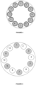
- Figure 3 depicts two cross sections of two exemplary homogeneous multi-core fibers, a first 12-cores fiber comprising 12 cores of identical types arranged on a ring around the fiber axis, and a second 19-cores fiber comprising 18 cores arranged on the edges of the hexagon and a central core.
- the multi-core fiber may be a homogeneous trench-assisted multi-core fiber, each core being surrounded by a low-index trench layer.
- Figure 4 illustrates a cross section of an exemplary trench-assisted homogeneous multi-core fiber comprising 12 cores of identical types.
- the multi-core fiber may be a heterogeneous multi-core fiber comprising a plurality of cores among which at least two cores are of different types.
- Each core in such heterogeneous multi-core fiber has two neighbors, each core having a core type different from the core type of its neighbor cores.
- FIG. 6 illustrates the cross sections of two exemplary 7-cores fiber and 19-cores heterogeneous fibers.
- the 7-cores fiber comprises six cores on the edges of the hexagon numbered 1-6 and a central core numbered 7.
- Such 7-core fiber involves three different core types, the central core having a core type different from the types of the cores on the edges of the hexagon, and each core arranged on the edges of the hexagon having a core type different from the core type of its neighbor cores.
- the 19-cores fiber comprises three different core types, the central core having a core type different from the types of the cores on the edges of the hexagon.
- the multi-core fiber may be a trench-assisted heterogeneous multi-core fiber.
- Figure 7 depicts two cross sections of two exemplary 12-cores and 7-cores trench-assisted heterogeneous multi-core fibers.
- each core of the multi-core fiber may be single mode comprising one spatial propagation mode.
- the multi-core fiber may comprise at least one multi-mode core comprising two or more spatial propagation modes.
- the optical fiber transmission channel 13 may further comprise one or more amplifiers 132 inserted in the fiber for re-amplifying the optical power and compensating for the fiber attenuation without the need to regenerate the optical signals such that a sufficient signal power can be maintained over large distance where optical signals need to be periodically amplified.
- the amplifiers 132 may be inserted between each pair of fiber slices 131.
- an amplifier 132 inserted at the end of the optical fiber transmission channel performs signal amplification before signal detection at the receiver 15.
- Each amplifier 132 may be configured to simultaneously amplify the optical signal corresponding to the plurality of cores in the multi-core fiber.
- the amplifiers 132 may consist of a duplication of a single core fiber amplifier.
- an amplifier 132 may be an optical multi-core amplifier.
- Exemplary optical amplifiers comprise multi-core Erbium doped fiber amplifiers (EDFAs) such as core-pumped multi-core EDFAs and cladding-pumped EDFA amplifiers.
- EDFAs Erbium doped fiber amplifiers
- Core-pumped and cladding pumped amplifiers may use a single or a plurality of pump diodes.
- a pump diode per core may be used in EDFA amplifiers.
- the optical signal amplification may be performed in a distributed manner using the non-linear simulated Raman scattering effect.
- the fiber is used as both a transmission link and an amplification medium.
- signal amplification may be achieved by a joint use of regularly arranged optical amplifiers and of simulated Raman Scattering effects.
- the signal amplification may be performed in the electrical domain through an optical/electrical conversion (not illustrated in figure 1 ).
- the optical fiber transmission channel 13 may comprise, at each amplification stage:
- the optical transmission channel 13 may further comprise one or more of:
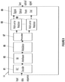
- FIG. 8 shows the block structure of an optical transmitter 11 according to some embodiments of the invention.
- the optical transmitter 11 may be configured to transform an input data sequence into an optical signal to be transmitted through the optical transmission channel 13.
- the optical transmitter 11 may comprise a Forward Error Correcting code (FEC) encoder 81 (also referred to as 'an error correcting code encoder 81') configured to encode an input data sequence of length k (i.e. comprising k symbols) into an encoded sequence in the form of a codeword vector of length n > k by applying at least one Forward Error Correcting code (FEC) (also referred to as 'an error correcting code').
- FEC Forward Error Correcting code
- FEC Forward Error Correcting code
- the input data sequence may be a binary sequence comprising k bits.
- the FEC encoder 81 may be configured, in such embodiments, to encode the input binary sequence into a binary codeword vector comprising n bits by applying at least one binary FEC code.
- the input data sequence may comprise symbols that take values in a Galois Field GF ( q ) with q > 2 representing the order of the Galois Field.
- the FEC encoder 22 may be configured to encode the input data sequence into a codeword vector comprising n symbols, each symbol comprised in the codeword vector takes value in the Galois Field GF ( q ) .
- the encoding process in this case may be performed using a non-binary FEC code constructed over GF ( q ) with q > 2.
- the FEC encoder 81 By performing the coding operation, the FEC encoder 81 adds redundant bits (in general redundant symbols) to the input binary sequence so that the receiver can detect and/or correct common transmission errors.
- redundant bits in general redundant symbols
- the use of a FEC code provides an additional protection and immunity against transmission errors and allows significant improvement in performance with respect to uncoded transmission (i.e. transmission of modulated data without FEC encoding).
- Concatenation of codes may follow a serial, a parallel, or a multi-level architecture.
- the FEC encoder 81 may be accordingly configured to implement two or more FEC codes.
- the optical transmitter 11 may further comprise an interleaver 83 configured to mix the encoded sequence to add a protection layer to the encoded symbols against burst errors.
- the interleaved encoded sequence may be then processed by a modulator 85 configured to determine a set of modulated symbols in a form of a modulated symbol vector s c by applying a modulation scheme to the interleaved encoded sequence (or to the codeword vectors in embodiments where the transmitter 11 does not comprise an interleaver).
- Different modulation schemes may be implemented such as 2 q -QAM or 2 q -PSK with 2 q symbols or states.
- the modulated vector s c may be a complex-value vector comprising ⁇ complex-value symbols s 1 , s 2 , ...
- the 2 q symbols or states represent a sub-set of the integer field Z i .
- the corresponding constellation is composed of 2 q points representing the different states or symbols.
- the optical transmitter 11 implements linear precoding techniques to precode the vector of information symbols into a precoded vector denoted s p using a precoding matrix denoted P ⁇ C N c x N c and comprising complex values.
- the precoded vector s p ⁇ C N c is a vector of dimension N c comprising complex values.
- the embodiments of the invention provide efficient linear precoding techniques to pre-compensate the channel effect at the optical transmitter.
- Existing linear precoding techniques used in wireless communication systems rely on perfect channel state information at the transmitter where the receiver communicates an estimate of the channel matrix to the transmitter via a feedback link.
- the embodiments of the invention provide linear precoding techniques that do not require feedback from the receiver to send the estimated channel matrix to the transmitter and consider an auxiliary matrix (also referred to as 'auxiliary channel matrix') denoted H that is determined based on a channel model defining the multicore fiber transmission channel.
- auxiliary matrix also referred to as 'auxiliary channel matrix'
- the multicore channel model is implemented at the optical transmitter to predict and estimate the performance behavior of the multicore fiber transmission channel by evaluating the core dependent loss for the multi-core fiber transmission channel made of a multi-core fiber associated with predefined fiber configuration and fiber parameters and misalignment losses values.
- ⁇ n also referred to as 'a core loss value'
- the fiber parameters comprise a fiber length L, a number of cores N c ⁇ 2 at least equal to two, crosstalk coefficients XT n,m with n, m ⁇ ⁇ 1, ... , N c ⁇ , and coupling coefficients k n,m with n, m ⁇ ⁇ 1, ... , N c ⁇ , each crosstalk coefficient XT n,m representing a crosstalk between the core- n and the core- m with n ⁇ m in the multi-core fiber, each coupling coefficient k n,m representing a coupling the core- n and the core- m with n # m in the multi-core fiber.
- the fiber parameters may further comprise a bending radius, a number of fiber slices K, the cladding diameter, the radius of each core of the multi-core fiber, and the type of each core of the multi-core fiber.
- the misalignment losses may rise due to the imperfections of the optical fiber at the fiber spans and of the connectors (e.g. the connectors between the FAN-IN/FAN-OUT devices and the input/output ends of the optical fiber transmission channel).
- Misalignment losses may comprise a misalignment chosen in a group comprising a longitudinal misalignment, a transverse misalignment, and angular misalignment.
- r d designates the transverse displacement of the multi-core fiber in the 'x' and ⁇ y' directions.
- the optical channel noise may be a White Gaussian Noise of zero-mean and variance N 0 .
- H XT XT 1 XT 1,2 ... XT 1 , N c XT 2,1 ⁇ ... XT 2 , N c ⁇ ⁇ ⁇ ⁇ XT N c , 1 XT N c , 2 ⁇ XT N c , N c
- the crosstalk represents the exchanging energy between the cores and can be estimated based on the coupled-power theory, known to the person skilled in the art.
- ⁇ designates the core-to-core distance and ⁇ 2 is the propagation constant.
- ⁇ i designates the total misalignment loss coefficient associated with the core core- i
- XT i 1 - ⁇ i ⁇ m
- XT i,m designates a total crosstalk coefficient quantifying the total crosstalk associated with the core core- i at the end of the optical transmission channel 13, the total crosstalk coefficient associated with the core core- i being dependent on the crosstalk coefficients quantifying the crosstalk between said core core- i and the remaining cores in the multi-core fiber.
- the precoder 87 may be configured to determine the mean value ⁇ ⁇ n of each core loss value ⁇ n associated with each core core- n of the multi-core fiber as the product between a first value and a second value, the first value ⁇ ⁇ n corresponding to the mean of the lognormal random variable ⁇ n representing the total misalignment loss associated with the core core- n , the second value XT n 2 corresponding to the square of the total crosstalk coefficient associated with said the core core-n.
- the precoder 87 may be further configured to determine the variance value ⁇ ⁇ n 2 of each core loss value ⁇ n associated with each core core- n of the multi-core fiber as the product between the total crosstalk coefficient XT n associated with the core core- n and a third value corresponding to the variance ⁇ ⁇ n 2 of the lognormal random variable ⁇ n representing the total misalignment loss associated with the core core- n .
- the precoder 87 may be configured to determine an average channel matrix realization using the average values of the mathematical channel model. Accordingly, the precoder 87 may be configured to:
- the optical transmitter 11 may further comprise a plurality of multi-carrier modulators 88 configured to generate multi-carrier symbols by implementing a multi-carrier modulation technique within each optical carrier involving a large number of orthogonal sub-carriers. Moreover, multi-carrier modulations may be implemented for providing a better resistance to the inter-symbol interference resulting from the fiber dispersion.
- Exemplary multi-carrier modulation formats comprise Orthogonal Frequency Division Multiplexing (OFDM) and Filter Bank Multi-Carrier (FBMC).
- the frequency-domain signal delivered by the multicarrier modulators 88 may be then processed by a digital-optical Front-End 89 configured to convert the received frequency-domain signal to the optical domain.
- the digital-optical Front-End 88 may perform the conversion using a number of lasers of given wavelengths and a plurality of optical modulators (not shown in figure 8 ) associated with the used polarization states and the spatial propagation modes in the cores of the multi-core fiber.
- a laser may be configured to generate a laser beam of a same or different wavelength using Wavelength Division Multiplexing (WDM) techniques.
- WDM Wavelength Division Multiplexing
- the different laser beams may be then modulated using the different outputs of the OFDM symbols (or the different values of the precoded information symbols in embodiments using single-carrier modulations) by means of the optical modulators.
- the modulated signals may be then polarized according to the different polarization states of the fiber.
- Exemplary modulators comprise Mach-Zehnder modulators. A phase and/or amplitude modulation may be used.
- the modulation scheme used by the various optical modulators for modulating the different optical signals may be similar or different.
- the number of the optical modulators and lasers depends on the number of used polarization states, the number of used propagation modes in each core of the multi-core fiber, and on the number of cores in the fiber.
- the digital-optical front-end 88 may further comprise a FAN-IN device (not illustrated in figure 8 ) configured to inject the generated optical signals into each core of the multi-core fiber to propagate according to the available propagation modes in each core.
- Optical connectors may be used to connect the output end of the FAN-IN device and the input end of the multi-core optical transmission channel 13.
- optical signals generated according to any of the preceding embodiments may propagate along the fiber until reaching the other end of the optical transmission channel 13 where it is processed by an optical receiver 15.
- the transmitted signals should satisfy a transmit power constraint such that the total transmitted energy across all the N c cores of the multicore fiber is equal to N c .
- E 0 with E 0 designating the average signal energy transmitted per core.
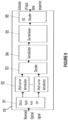
- Figure 9 is a block diagram of an optical receiver 15 according to some embodiments.
- the optical receiver 15 is configured to receive the optical signal transmitted by the optical transmitter 11 through the transmission channel 13 and to generate an estimate of the original input data sequence.
- the optical receiver 15 may comprise:
- the decoder 93 may implement a decoding algorithm chosen in a group consisting of a maximum likelihood (ML) decoder, a Zero-Forcing decoder, a Zero-Forcing Decision Feedback Equalizer, and a Minimum Mean Square Error decoder.
- Exemplary maximum likelihood decoders comprise the sphere decoder, the Schnorr-Euchner decoder, the stack decoder, the spherical-bound-stack decoder.
- Such ML decoders are sequential decoders that perform a tree-search in a decoding tree associated with the received received signal to search for the optimal ML solution.
- Sub-optimal implementations of the Stack decoder and the SB-stack decoder may further be used using a parameter known as 'a bias' parameter.
- the plurality of multi-carrier modulators 92 may be replaced by a single modulator.
- the multi-carrier demodulators 92 may be replaced by a single demodulator.
- a corresponding structure may be implemented by the FEC decoder 96.
- the FEC decoder 96 may comprise an inner code decoder, a de-interleaver, and an outer code decoder (not shown in figure 9 ).
- the FEC decoder 96 may comprise a de-multiplexer, a de-interleaver, and a joint decoder (not shown in figure 9 ).
- a vector of information symbols s c ⁇ C N c comprising N c complex values may be received.
- a precoding matrix P ⁇ C N c x N c may be determined.
- Figure 11 is a flowchart depicting the step 1003 for determining a precoding matrix P ⁇ C N c x N c according to some embodiments of the invention in which an auxiliary matrix determined based on a channel model defining the multicore fiber transmission channel is used to determine the precoding matrix.
- fiber parameters of the multi-core fiber and misalignment loss values may be received.
- the fiber parameters may comprise the number of cores N c ⁇ 2, the length L of the fiber, crosstalk coefficients XT n,m with n, m ⁇ ⁇ 1, ... , N c ⁇ , and coupling coefficients k n,m with n, m ⁇ ⁇ 1, ... , N c ⁇ , each crosstalk coefficient XT n,m representing a crosstalk between the core- n and the core- m with n ⁇ m in the multi-core fiber, each coupling coefficient k n,m representing a coupling the core-n and the core-m with n ⁇ m in the multi-core fiber.
- misalignment losses comprise longitudinal misalignments, transverse misalignments, and angular misalignments.
- the misalignment losses values may be previously determined according to equation (1).
- the mean value ⁇ ⁇ n of each core loss value ⁇ n associated with each core core-n of the multi-core fiber may be determined as the product between a first value and a second value, the first value ⁇ ⁇ n corresponding to the mean of the lognormal random variable ⁇ n representing the total misalignment loss associated with the core core- n , the second value XT n 2 corresponding to the square of the total crosstalk coefficient associated with the core core- n .
- the variance value ⁇ ⁇ n 2 of each core loss value ⁇ n associated with each core core- n of the multi-core fiber may be determined as the product between the total crosstalk coefficient XT n associated with the core core- n and a third value corresponding to the variance ⁇ ⁇ n 2 of the lognormal random variable ⁇ n representing the total misalignment loss associated with the core core- n .
- a first unitary matrix U r ⁇ C N c x N c and a second unitary matrix V r ⁇ C N c x N c may be determined randomly.
- a diagonal matrix ⁇ comprising diagonal components may be determined.
- the diagonal components are equal to the mean values of the random variables defining the core loss values associated with the two or more cores such that the n th diagonal component is the mean value ⁇ ⁇ n of the core loss value ⁇ n associated with the n th of the multicore fiber according to equation (14).
- an auxiliary matrix H may be determined as the product between the square root of the normalization factor l , the first unitary matrix U r , the diagonal matrix ⁇ , and the second unitary matrix V r according to equation (15).
- Performance of the proposed linear precoding techniques (referred to as 'ZF pre-compensation') has been evaluated in terms of bit error rate and compared to the performance obtained for the Gaussian channel in which the core dependent loss is null, and to the performance obtained using deterministic core scrambling.
- Two multicore fibers are considered, a 7-core heterogeneous multicore fiber with three core types is used in combination with snail scrambling, and a 12-core heterogeneous multicore fiber with two types of cores is used in combination with circular scrambling.
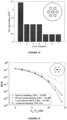
- Figure 12 illustrates the eigenvalues of the transmitted signal after linear precoding for the 7-core fiber and unitary average energy transmitted per core. Numerical results show that the sum of the eigenvalues is equal to seven ( ⁇ 7') which satisfies the linear regime constraints and the total power constraint.
- Figure 13 illustrates diagrams evaluating the bit error rate performance function of the signal-to-noise ratio obtained in a 7-core heterogeneous fiber for snail scrambling-based transmission system using 6 snail scramblers, ZF pre-compensation according to the embodiments of the invention, the Gaussian channel (CDL free), and the 7-core heterogeneous fiber without scrambling nor precoding.
- Figure 14 illustrates diagrams evaluating the bit error rate performance function of the signal-to-noise ratio obtained in a 12-core heterogeneous fiber for circular scrambling-based transmission system using one circular scrambler, ZF pre-compensation according to the embodiments of the invention, the Gaussian channel (CDL free), and the 12-core heterogeneous fiber without scrambling nor precoding.
- the invention is not limited to communication applications and may be integrated in other applications such as data storage and medical imaging.
- the invention may be used in several optical transmission systems, for example automotive industry applications, in oil or gas markets, in aerospace and avionics sectors, sensing applications, etc.
Landscapes
- Engineering & Computer Science (AREA)
- Computer Networks & Wireless Communication (AREA)
- Signal Processing (AREA)
- Physics & Mathematics (AREA)
- Electromagnetism (AREA)
- Optics & Photonics (AREA)
- Optical Communication System (AREA)
Claims (9)
- Émetteur optique (11) pour transmettre un vecteur de symboles d'information sur un canal de transmission à fibre optique (13), ledit canal de transmission à fibre comprenant une fibre multicoeur, ledit vecteur de symboles d'information étant transporté par des signaux optiques se propageant le long de la fibre multicoeur selon deux coeurs ou plus, dans lequel l'émetteur optique (11) comprend un précodeur (87) configuré pour déterminer une matrice précodante en utilisant un ou plusieurs paramètres de fibre associés à ladite fibre multicoeur et pour précoder ledit vecteur de symboles d'information en multipliant le vecteur de symboles d'information par ladite matrice précodante, caractérisé en ce que le précodeur (87) est configuré pour déterminer une valeur de perte de coeur associée à chacun desdits deux coeurs ou plus en fonction desdits paramètres de fibre et d'au moins une valeur de perte par défaut d'alignement, chaque valeur de perte de coeur étant une variable aléatoire d'une distribution lognormale définie par une valeur moyenne et une valeur de variance, lesdites valeur moyenne et valeur de variance dépendant des paramètres de la fibre et de la au moins une valeur de perte par défaut d'alignement.
- Émetteur optique selon la revendication 1, dans lequel le précodeur (87) est configuré pour :- déterminer un facteur de normalisation comme le rapport entre un nombre desdits deux ou plusieurs coeurs et une somme des valeurs de perte de coeur associées auxdits deux ou plusieurs coeurs ;- déterminer, de manière aléatoire, une première matrice unitaire et une deuxième matrice unitaire ;- déterminer une matrice diagonale comprenant des composantes diagonales, lesdites composantes diagonales étant égales aux valeurs moyennes des variables aléatoires définissant les valeurs de perte de coeur associées auxdits deux ou plusieurs coeurs ;- déterminer une matrice auxiliaire comme le produit entre la racine carrée du facteur de normalisation, la première matrice unitaire, la matrice diagonale et la deuxième matrice unitaire ;le précodeur étant configuré pour déterminer ladite matrice précodante comme l'inverse de ladite matrice auxiliaire.
- Émetteur optique (11) selon l'une quelconque des revendications précédentes, dans lequel lesdits un ou plusieurs paramètres de fibre comprennent au moins un paramètre parmi une longueur de fibre, un nombre de coeurs correspondant au nombre desdits deux ou plusieurs coeurs, au moins un coefficient de diaphonie , et au moins un coefficient de couplage, un coefficient de diaphonie représentant une diaphonie entre deux coeurs dans la fibre multicoeur, un coefficient de couplage représentant un couplage entre deux coeurs dans la fibre multicoeur.
- Émetteur optique (11) selon la revendication 1 ou 2, dans lequel lesdites valeurs de perte par défaut d'alignement représentent un désalignement de la fibre multicoeur choisie dans un groupe comprenant un désalignement longitudinal, un alignement transversal, et un alignement angulaire.
- Émetteur optique (11) selon l'une quelconque des revendications précédentes 1 et 2, dans lequel le précodeur (87) est configuré pour déterminer chaque valeur moyenne d'une valeur de perte de coeur associée à chaque coeur comme le produit entre une première valeur et une seconde valeur, la première valeur correspondant à la moyenne d'une variable aléatoire lognormale représentant une perte totale par désalignement associée à chaque dit noyau, la deuxième valeur correspondant à un coefficient de diaphonie total associé audit chaque noyau, le précodeur (87) étant configuré pour déterminer le coefficient de diaphonie total associé à un coeur donné parmi les coefficients de diaphonie représentant la diaphonie entre ledit coeur donné et les coeurs de la fibre multicoeur différents dudit coeur donné, le précodeur (87) étant en outre configuré pour déterminer la valeur de variance de chaque valeur de perte de coeur associé à chaque coeur de la fibre multicoeur comme le produit entre le carré du coefficient de diaphonie total associé audit chaque coeur et une troisième valeur correspondant à la variance de ladite variable aléatoire lognormale représentant la perte totale par désalignement associée à chaque dit coeur.
- Émetteur optique (11) selon l'une quelconque des revendications précédentes, dans lequel l'émetteur optique (11) comprend en outre :- un codeur de code de correction d'erreurs (81) configuré pour coder lesdites données dans un vecteur de mot de code en appliquant au moins un code de correction d'erreurs ;- un modulateur (85) configuré pour déterminer le vecteur de symboles d'information en appliquant un schéma de modulation audit vecteur de mot de code.
- Système de transmission optique comprenant un émetteur optique (11) selon l'une quelconque des revendications précédentes 1 à 6 et un récepteur (15) configuré pour recevoir et décoder les signaux optiques transportant des données transmises par ledit émetteur optique à travers ledit canal de transmission à fibre optique (13).
- Procédé de transmission d'un vecteur de symboles d'information sur un canal de transmission à fibre optique constitué d'une fibre multicoeur, des signaux optiques portant ledit vecteur de symboles d'information se propageant le long de la fibre multicoeur selon deux ou plusieurs coeurs, dans lequel, un précodeur détermine (1003) une matrice précodante en utilisant un ou plusieurs paramètres de fibre associés à ladite fibre multicoeur et précode (1003) ledit vecteur de symboles d'information en multipliant le vecteur de symboles d'information par ladite matrice précodante,
caractérisé en ce que un précodeur détermine (1103) une valeur de perte de coeur associée à chacun desdits au moins deux coeurs en fonction de paramètres de fibre et d'au moins une valeur de perte par défaut d'alignement, chaque valeur de perte de coeur étant une variable aléatoire d'une distribution lognormale définie par une valeur moyenne et une valeur de variance, lesdites valeur moyenne et valeur de variance dépendant des paramètres de la fibre et de la au moins une valeur de perte par défaut d'alignement. - Procédé selon la revendication 8, comprenant cependant en outre :- déterminer (1105) un facteur de normalisation comme le rapport entre un nombre desdits deux coeurs ou plus et une somme des valeurs de perte de coeur associées auxdits deux coeurs ou plus ;- déterminer de manière aléatoire (1107) une première matrice unitaire et une seconde matrice unitaire ;- déterminer (1109) une matrice diagonale comprenant des composantes diagonales, lesdites composantes diagonales étant égales aux valeurs moyennes des variables aléatoires définissant les valeurs de perte de coeur associées auxdits deux ou plusieurs coeurs ;- déterminer (1111) une matrice auxiliaire comme le produit entre le facteur de normalisation, la première matrice unitaire, la matrice diagonale et la seconde matrice unitaire ;- déterminer (1113) ladite matrice précodante comme l'inverse de ladite matrice auxiliaire.
Priority Applications (6)
| Application Number | Priority Date | Filing Date | Title |
|---|---|---|---|
| EP19290058.7A EP3767841B1 (fr) | 2019-07-17 | 2019-07-17 | Procédés et dispositifs de transmission de données de fibres multicoeur utilisant un précodage de données |
| KR1020227000776A KR102749072B1 (ko) | 2019-07-17 | 2020-06-23 | 데이터 프리코딩을 이용한 멀티-코어 섬유 데이터 송신을 위한 방법들 및 디바이스들 |
| US17/621,422 US11916597B2 (en) | 2019-07-17 | 2020-06-23 | Methods and devices for multi-core fiber data transmission using data precoding |
| CN202080050973.XA CN114144980B (zh) | 2019-07-17 | 2020-06-23 | 发送信息符号向量的光发送器及其发送方法与光接收器 |
| PCT/EP2020/067408 WO2021008821A1 (fr) | 2019-07-17 | 2020-06-23 | Procédés et dispositifs de transmission de données par fibres multicœurs à l'aide d'un précodage de données |
| JP2021574805A JP7602492B2 (ja) | 2019-07-17 | 2020-06-23 | データプリコーディングを使用するマルチコアファイバデータ伝送のための方法及び装置 |
Applications Claiming Priority (1)
| Application Number | Priority Date | Filing Date | Title |
|---|---|---|---|
| EP19290058.7A EP3767841B1 (fr) | 2019-07-17 | 2019-07-17 | Procédés et dispositifs de transmission de données de fibres multicoeur utilisant un précodage de données |
Publications (3)
| Publication Number | Publication Date |
|---|---|
| EP3767841A1 EP3767841A1 (fr) | 2021-01-20 |
| EP3767841B1 true EP3767841B1 (fr) | 2024-08-28 |
| EP3767841C0 EP3767841C0 (fr) | 2024-08-28 |
Family
ID=67614532
Family Applications (1)
| Application Number | Title | Priority Date | Filing Date |
|---|---|---|---|
| EP19290058.7A Active EP3767841B1 (fr) | 2019-07-17 | 2019-07-17 | Procédés et dispositifs de transmission de données de fibres multicoeur utilisant un précodage de données |
Country Status (6)
| Country | Link |
|---|---|
| US (1) | US11916597B2 (fr) |
| EP (1) | EP3767841B1 (fr) |
| JP (1) | JP7602492B2 (fr) |
| KR (1) | KR102749072B1 (fr) |
| CN (1) | CN114144980B (fr) |
| WO (1) | WO2021008821A1 (fr) |
Families Citing this family (2)
| Publication number | Priority date | Publication date | Assignee | Title |
|---|---|---|---|---|
| EP3627725B1 (fr) * | 2018-09-18 | 2022-04-06 | Institut Mines-Telecom | Dispositifs et procédés de décodage adaptatif et de brouillage de coeur dans des systèmes de transmission par fibre multi-coeur |
| CN119696781B (zh) * | 2025-01-02 | 2025-12-12 | 广东工业大学 | 一种多芯光纤通信中的物理层安全密钥分发装置和方法 |
Family Cites Families (13)
| Publication number | Priority date | Publication date | Assignee | Title |
|---|---|---|---|---|
| GB0325584D0 (en) * | 2003-11-03 | 2003-12-03 | Srodzinski David N | Method and apparatus for adapting an information carrying signal |
| US8503845B2 (en) * | 2011-01-17 | 2013-08-06 | Alcatel Lucent | Multi-core optical fiber and optical communication systems |
| FR2977099B1 (fr) * | 2011-06-23 | 2014-02-21 | Telecom Paris Tech | Methode et systeme de transmission sur fibre optique multi-mode et/ou multi-coeur |
| US20170019178A1 (en) * | 2014-02-24 | 2017-01-19 | The Regents Of The University Of California | Nonlinearity cancellation in fiber optic transmission based on frequency-mutually-referenced carriers |
| FR3023436B1 (fr) * | 2014-07-01 | 2016-08-19 | Telecom Paris Tech | Methode et systeme de transmission sur fibre optique a brassage de modes et/ou de cœurs |
| EP3758250B1 (fr) * | 2015-05-14 | 2024-03-13 | Telefonaktiebolaget LM Ericsson (publ) | Configuration de signaux de référence de mesurage pour mimo |
| EP3273624B1 (fr) * | 2016-07-18 | 2025-02-19 | Institut Mines Telecom | Codage spatio-temporel et fec dans des systèmes de transmission optique à fibre multimode |
| US10644908B2 (en) * | 2017-08-29 | 2020-05-05 | Cable Laboratories, Inc | System and methods for multi-level signal transmission |
| EP3547572A1 (fr) * | 2018-03-30 | 2019-10-02 | Nokia Solutions and Networks Oy | Procédé pour générer un signal optique et émetteur optique et récepteur optique associés |
| EP3562066A1 (fr) * | 2018-04-27 | 2019-10-30 | Institut Mines-Telecom | Système de transmission optique et procédé de sélection de noyau dans des fibres multic urs |
| EP3562063B1 (fr) * | 2018-04-27 | 2022-06-29 | Institut Mines-Telecom | Système de transmission optique et procédé de brouillage d'âme de fibres optiques multicoeurs |
| EP3562065A1 (fr) * | 2018-04-27 | 2019-10-30 | Institut Mines-Telecom | Procédés et dispositifs pour la détermination de perte dépendant du noyau dans des systèmes de transmission à fibre multic ur utilisant le brouillage de noyau |
| EP3562064A1 (fr) * | 2018-04-27 | 2019-10-30 | Institut Mines-Telecom | Procédés et dispositifs permettant de déterminer une perte dépendant d'un c ur dans des systèmes de transmission à fibres multi-c urs |
-
2019
- 2019-07-17 EP EP19290058.7A patent/EP3767841B1/fr active Active
-
2020
- 2020-06-23 KR KR1020227000776A patent/KR102749072B1/ko active Active
- 2020-06-23 CN CN202080050973.XA patent/CN114144980B/zh active Active
- 2020-06-23 US US17/621,422 patent/US11916597B2/en active Active
- 2020-06-23 JP JP2021574805A patent/JP7602492B2/ja active Active
- 2020-06-23 WO PCT/EP2020/067408 patent/WO2021008821A1/fr not_active Ceased
Also Published As
| Publication number | Publication date |
|---|---|
| CN114144980B (zh) | 2024-05-24 |
| US11916597B2 (en) | 2024-02-27 |
| EP3767841A1 (fr) | 2021-01-20 |
| US20220376789A1 (en) | 2022-11-24 |
| WO2021008821A1 (fr) | 2021-01-21 |
| JP7602492B2 (ja) | 2024-12-18 |
| KR20220034773A (ko) | 2022-03-18 |
| JP2022541105A (ja) | 2022-09-22 |
| EP3767841C0 (fr) | 2024-08-28 |
| KR102749072B1 (ko) | 2024-12-31 |
| CN114144980A (zh) | 2022-03-04 |
Similar Documents
| Publication | Publication Date | Title |
|---|---|---|
| US11539438B2 (en) | Methods and devices for the determination of core dependent loss in multi-core fiber transmission systems | |
| US11239917B2 (en) | Methods and devices for the determination of core dependent loss in multi-core fiber transmission systems using core scrambling | |
| US11637631B2 (en) | Optical transmission system and method for core scrambling for multicore optical fibers | |
| EP3627725B1 (fr) | Dispositifs et procédés de décodage adaptatif et de brouillage de coeur dans des systèmes de transmission par fibre multi-coeur | |
| US11916597B2 (en) | Methods and devices for multi-core fiber data transmission using data precoding | |
| US11218218B2 (en) | Optical transmission system and method for core selection in multi-core fibers | |
| JP2021522727A5 (fr) |
Legal Events
| Date | Code | Title | Description |
|---|---|---|---|
| PUAI | Public reference made under article 153(3) epc to a published international application that has entered the european phase |
Free format text: ORIGINAL CODE: 0009012 |
|
| STAA | Information on the status of an ep patent application or granted ep patent |
Free format text: STATUS: THE APPLICATION HAS BEEN PUBLISHED |
|
| AK | Designated contracting states |
Kind code of ref document: A1 Designated state(s): AL AT BE BG CH CY CZ DE DK EE ES FI FR GB GR HR HU IE IS IT LI LT LU LV MC MK MT NL NO PL PT RO RS SE SI SK SM TR |
|
| AX | Request for extension of the european patent |
Extension state: BA ME |
|
| STAA | Information on the status of an ep patent application or granted ep patent |
Free format text: STATUS: REQUEST FOR EXAMINATION WAS MADE |
|
| 17P | Request for examination filed |
Effective date: 20210706 |
|
| RBV | Designated contracting states (corrected) |
Designated state(s): AL AT BE BG CH CY CZ DE DK EE ES FI FR GB GR HR HU IE IS IT LI LT LU LV MC MK MT NL NO PL PT RO RS SE SI SK SM TR |
|
| RAP3 | Party data changed (applicant data changed or rights of an application transferred) |
Owner name: INSTITUT MINES TELECOM |
|
| STAA | Information on the status of an ep patent application or granted ep patent |
Free format text: STATUS: EXAMINATION IS IN PROGRESS |
|
| 17Q | First examination report despatched |
Effective date: 20230327 |
|
| GRAP | Despatch of communication of intention to grant a patent |
Free format text: ORIGINAL CODE: EPIDOSNIGR1 |
|
| STAA | Information on the status of an ep patent application or granted ep patent |
Free format text: STATUS: GRANT OF PATENT IS INTENDED |
|
| INTG | Intention to grant announced |
Effective date: 20240522 |
|
| GRAS | Grant fee paid |
Free format text: ORIGINAL CODE: EPIDOSNIGR3 |
|
| GRAA | (expected) grant |
Free format text: ORIGINAL CODE: 0009210 |
|
| STAA | Information on the status of an ep patent application or granted ep patent |
Free format text: STATUS: THE PATENT HAS BEEN GRANTED |
|
| AK | Designated contracting states |
Kind code of ref document: B1 Designated state(s): AL AT BE BG CH CY CZ DE DK EE ES FI FR GB GR HR HU IE IS IT LI LT LU LV MC MK MT NL NO PL PT RO RS SE SI SK SM TR |
|
| REG | Reference to a national code |
Ref country code: GB Ref legal event code: FG4D |
|
| REG | Reference to a national code |
Ref country code: CH Ref legal event code: EP |
|
| REG | Reference to a national code |
Ref country code: DE Ref legal event code: R096 Ref document number: 602019057807 Country of ref document: DE |
|
| REG | Reference to a national code |
Ref country code: IE Ref legal event code: FG4D |
|
| U01 | Request for unitary effect filed |
Effective date: 20240919 |
|
| U07 | Unitary effect registered |
Designated state(s): AT BE BG DE DK EE FI FR IT LT LU LV MT NL PT RO SE SI Effective date: 20240925 |
|
| PG25 | Lapsed in a contracting state [announced via postgrant information from national office to epo] |
Ref country code: NO Free format text: LAPSE BECAUSE OF FAILURE TO SUBMIT A TRANSLATION OF THE DESCRIPTION OR TO PAY THE FEE WITHIN THE PRESCRIBED TIME-LIMIT Effective date: 20241128 |
|
| PG25 | Lapsed in a contracting state [announced via postgrant information from national office to epo] |
Ref country code: GR Free format text: LAPSE BECAUSE OF FAILURE TO SUBMIT A TRANSLATION OF THE DESCRIPTION OR TO PAY THE FEE WITHIN THE PRESCRIBED TIME-LIMIT Effective date: 20241129 Ref country code: PL Free format text: LAPSE BECAUSE OF FAILURE TO SUBMIT A TRANSLATION OF THE DESCRIPTION OR TO PAY THE FEE WITHIN THE PRESCRIBED TIME-LIMIT Effective date: 20240828 |
|
| PG25 | Lapsed in a contracting state [announced via postgrant information from national office to epo] |
Ref country code: IS Free format text: LAPSE BECAUSE OF FAILURE TO SUBMIT A TRANSLATION OF THE DESCRIPTION OR TO PAY THE FEE WITHIN THE PRESCRIBED TIME-LIMIT Effective date: 20241228 |
|
| PG25 | Lapsed in a contracting state [announced via postgrant information from national office to epo] |
Ref country code: HR Free format text: LAPSE BECAUSE OF FAILURE TO SUBMIT A TRANSLATION OF THE DESCRIPTION OR TO PAY THE FEE WITHIN THE PRESCRIBED TIME-LIMIT Effective date: 20240828 |
|
| PG25 | Lapsed in a contracting state [announced via postgrant information from national office to epo] |
Ref country code: ES Free format text: LAPSE BECAUSE OF FAILURE TO SUBMIT A TRANSLATION OF THE DESCRIPTION OR TO PAY THE FEE WITHIN THE PRESCRIBED TIME-LIMIT Effective date: 20240828 Ref country code: RS Free format text: LAPSE BECAUSE OF FAILURE TO SUBMIT A TRANSLATION OF THE DESCRIPTION OR TO PAY THE FEE WITHIN THE PRESCRIBED TIME-LIMIT Effective date: 20241128 |
|
| PG25 | Lapsed in a contracting state [announced via postgrant information from national office to epo] |
Ref country code: RS Free format text: LAPSE BECAUSE OF FAILURE TO SUBMIT A TRANSLATION OF THE DESCRIPTION OR TO PAY THE FEE WITHIN THE PRESCRIBED TIME-LIMIT Effective date: 20241128 Ref country code: PL Free format text: LAPSE BECAUSE OF FAILURE TO SUBMIT A TRANSLATION OF THE DESCRIPTION OR TO PAY THE FEE WITHIN THE PRESCRIBED TIME-LIMIT Effective date: 20240828 Ref country code: NO Free format text: LAPSE BECAUSE OF FAILURE TO SUBMIT A TRANSLATION OF THE DESCRIPTION OR TO PAY THE FEE WITHIN THE PRESCRIBED TIME-LIMIT Effective date: 20241128 Ref country code: IS Free format text: LAPSE BECAUSE OF FAILURE TO SUBMIT A TRANSLATION OF THE DESCRIPTION OR TO PAY THE FEE WITHIN THE PRESCRIBED TIME-LIMIT Effective date: 20241228 Ref country code: HR Free format text: LAPSE BECAUSE OF FAILURE TO SUBMIT A TRANSLATION OF THE DESCRIPTION OR TO PAY THE FEE WITHIN THE PRESCRIBED TIME-LIMIT Effective date: 20240828 Ref country code: GR Free format text: LAPSE BECAUSE OF FAILURE TO SUBMIT A TRANSLATION OF THE DESCRIPTION OR TO PAY THE FEE WITHIN THE PRESCRIBED TIME-LIMIT Effective date: 20241129 Ref country code: ES Free format text: LAPSE BECAUSE OF FAILURE TO SUBMIT A TRANSLATION OF THE DESCRIPTION OR TO PAY THE FEE WITHIN THE PRESCRIBED TIME-LIMIT Effective date: 20240828 |
|
| PG25 | Lapsed in a contracting state [announced via postgrant information from national office to epo] |
Ref country code: SM Free format text: LAPSE BECAUSE OF FAILURE TO SUBMIT A TRANSLATION OF THE DESCRIPTION OR TO PAY THE FEE WITHIN THE PRESCRIBED TIME-LIMIT Effective date: 20240828 |
|
| PG25 | Lapsed in a contracting state [announced via postgrant information from national office to epo] |
Ref country code: CZ Free format text: LAPSE BECAUSE OF FAILURE TO SUBMIT A TRANSLATION OF THE DESCRIPTION OR TO PAY THE FEE WITHIN THE PRESCRIBED TIME-LIMIT Effective date: 20240828 |
|
| PG25 | Lapsed in a contracting state [announced via postgrant information from national office to epo] |
Ref country code: SK Free format text: LAPSE BECAUSE OF FAILURE TO SUBMIT A TRANSLATION OF THE DESCRIPTION OR TO PAY THE FEE WITHIN THE PRESCRIBED TIME-LIMIT Effective date: 20240828 |
|
| PLBE | No opposition filed within time limit |
Free format text: ORIGINAL CODE: 0009261 |
|
| STAA | Information on the status of an ep patent application or granted ep patent |
Free format text: STATUS: NO OPPOSITION FILED WITHIN TIME LIMIT |
|
| 26N | No opposition filed |
Effective date: 20250530 |
|
| U20 | Renewal fee for the european patent with unitary effect paid |
Year of fee payment: 7 Effective date: 20250721 |
|
| REG | Reference to a national code |
Ref country code: CH Ref legal event code: H13 Free format text: ST27 STATUS EVENT CODE: U-0-0-H10-H13 (AS PROVIDED BY THE NATIONAL OFFICE) Effective date: 20260224 |
|
| GBPC | Gb: european patent ceased through non-payment of renewal fee |
Effective date: 20250717 |
|
| PG25 | Lapsed in a contracting state [announced via postgrant information from national office to epo] |
Ref country code: GB Free format text: LAPSE BECAUSE OF NON-PAYMENT OF DUE FEES Effective date: 20250717 |
|
| PG25 | Lapsed in a contracting state [announced via postgrant information from national office to epo] |
Ref country code: CH Free format text: LAPSE BECAUSE OF NON-PAYMENT OF DUE FEES Effective date: 20250731 |