EP3767861A1 - Steuerkanalsendeverfahren, gerät und vorrichtung, detektionsverfahren, gerät und vorrichtung sowie speichermedium - Google Patents
Steuerkanalsendeverfahren, gerät und vorrichtung, detektionsverfahren, gerät und vorrichtung sowie speichermedium Download PDFInfo
- Publication number
- EP3767861A1 EP3767861A1 EP19766508.6A EP19766508A EP3767861A1 EP 3767861 A1 EP3767861 A1 EP 3767861A1 EP 19766508 A EP19766508 A EP 19766508A EP 3767861 A1 EP3767861 A1 EP 3767861A1
- Authority
- EP
- European Patent Office
- Prior art keywords
- control channel
- control
- channel
- information
- transmission configuration
- Prior art date
- Legal status (The legal status is an assumption and is not a legal conclusion. Google has not performed a legal analysis and makes no representation as to the accuracy of the status listed.)
- Granted
Links
Images
Classifications
-
- H—ELECTRICITY
- H04—ELECTRIC COMMUNICATION TECHNIQUE
- H04L—TRANSMISSION OF DIGITAL INFORMATION, e.g. TELEGRAPHIC COMMUNICATION
- H04L5/00—Arrangements affording multiple use of the transmission path
- H04L5/0001—Arrangements for dividing the transmission path
- H04L5/0003—Two-dimensional division
- H04L5/0005—Time-frequency
- H04L5/0007—Time-frequency the frequencies being orthogonal, e.g. OFDM(A) or DMT
- H04L5/001—Time-frequency the frequencies being orthogonal, e.g. OFDM(A) or DMT the frequencies being arranged in component carriers
-
- H—ELECTRICITY
- H04—ELECTRIC COMMUNICATION TECHNIQUE
- H04W—WIRELESS COMMUNICATION NETWORKS
- H04W72/00—Local resource management
- H04W72/20—Control channels or signalling for resource management
- H04W72/23—Control channels or signalling for resource management in the downlink direction of a wireless link, i.e. towards a terminal
-
- H—ELECTRICITY
- H04—ELECTRIC COMMUNICATION TECHNIQUE
- H04L—TRANSMISSION OF DIGITAL INFORMATION, e.g. TELEGRAPHIC COMMUNICATION
- H04L5/00—Arrangements affording multiple use of the transmission path
- H04L5/003—Arrangements for allocating sub-channels of the transmission path
- H04L5/0044—Allocation of payload; Allocation of data channels, e.g. PDSCH or PUSCH
-
- H—ELECTRICITY
- H04—ELECTRIC COMMUNICATION TECHNIQUE
- H04L—TRANSMISSION OF DIGITAL INFORMATION, e.g. TELEGRAPHIC COMMUNICATION
- H04L5/00—Arrangements affording multiple use of the transmission path
- H04L5/003—Arrangements for allocating sub-channels of the transmission path
- H04L5/0053—Allocation of signalling, i.e. of overhead other than pilot signals
-
- H—ELECTRICITY
- H04—ELECTRIC COMMUNICATION TECHNIQUE
- H04L—TRANSMISSION OF DIGITAL INFORMATION, e.g. TELEGRAPHIC COMMUNICATION
- H04L5/00—Arrangements affording multiple use of the transmission path
- H04L5/003—Arrangements for allocating sub-channels of the transmission path
- H04L5/0053—Allocation of signalling, i.e. of overhead other than pilot signals
- H04L5/0057—Physical resource allocation for CQI
-
- H—ELECTRICITY
- H04—ELECTRIC COMMUNICATION TECHNIQUE
- H04L—TRANSMISSION OF DIGITAL INFORMATION, e.g. TELEGRAPHIC COMMUNICATION
- H04L5/00—Arrangements affording multiple use of the transmission path
- H04L5/0091—Signalling for the administration of the divided path, e.g. signalling of configuration information
- H04L5/0094—Indication of how sub-channels of the path are allocated
-
- H—ELECTRICITY
- H04—ELECTRIC COMMUNICATION TECHNIQUE
- H04W—WIRELESS COMMUNICATION NETWORKS
- H04W24/00—Supervisory, monitoring or testing arrangements
- H04W24/02—Arrangements for optimising operational condition
Definitions
- the present disclosure relates to the field of communications, for example, to a method, an apparatus and a device for sending a control channel, a method, an apparatus and a device for detecting a control channel, and a computer-readable storage medium.
- a control channel in a physical layer is a very precious resource, and the resource utilization rate of the control channel is an important factor affecting the transmission efficiency of a system.
- the resource utilization rate of the control channel is low and needs to be improved.
- the present disclosure provides a method, an apparatus and a device for sending a control channel, a method, an apparatus and a device for detecting a control channel, and a computer-readable storage medium, so as to improve a resource utilization rate of the control channel.
- the present disclosure provides a method for sending a control channel, the method includes steps described below.
- a sending end sends a first control channel using a first transmission configuration, where the first control channel carries first control information for indicating transmission configuration information of a data channel.
- the sending end sends a second control channel using a second transmission configuration, where the second control channel carries second control information for indicating transmission configuration information of the data channel.
- the present disclosure provides an apparatus for sending a control channel, the apparatus includes a configuration information acquisition unit and a sending unit.
- the configuration information acquisition unit is configured to acquire a first transmission configuration and a second transmission configuration.
- the sending unit is configured to send a first control channel using the first transmission configuration, and send a second control channel using the second transmission configuration; where the first control channel carries first control information for indicating transmission configuration information of a data channel; and the second control channel carries second control information for indicating transmission configuration information of the data channel.
- the present disclosure provides a device for sending a control channel, and the device includes a memory and a processor, where the memory stores a program which, when read and executed by the processor, implements the method for sending the control channel described above.
- the present disclosure provides a computer-readable storage medium.
- the computer-readable storage medium stores at least one program executable by at least one processor to implement the method for sending the control channel described above.
- the present disclosure provides a method for detecting a control channel, the method includes steps described below.
- a receiving end detects a first control channel using a first transmission configuration, and acquires first control information from the first control channel, where the first control information indicates transmission configuration information of a data channel.
- the receiving end detects a second control channel using a second transmission configuration, and acquires second control information from the second control channel, where the second control information indicates transmission configuration information of the data channel.
- the present disclosure provides an apparatus for detecting a control channel, the apparatus includes a configuration information acquisition unit and a detection unit.
- the configuration information acquisition unit is configured to acquire a first transmission configuration and a second transmission configuration.
- the detection unit is configured to detect a first control channel using the first transmission configuration, acquire first control information from the first control channel, detect a second control channel using the second transmission configuration, and acquire second control information from the second control channel; where the first control information indicates transmission configuration information of a data channel, and the second control information indicates transmission configuration information of the data channel.
- the present disclosure provides a device for detecting a control channel, the device includes a memory and a processor, the memory stores a program which, when read and executed by the processor, implements the method for detecting the control channel described above.
- the present disclosure provides a computer-readable storage medium.
- the computer-readable storage medium stores at least one program executable by at least one processor to implement the method for detecting the control channel described above.
- Various physical layer control signaling in 5G includes resource allocation information, a carrier indication, a bandwidth part (BWP) indication, an indication of a trigger for reporting aperiodic channel state information (CSI), an uplink power control command, hybrid automatic repeat request (HARQ) information, a demodulation reference signal (DMRS) configuration indication, an indication of a modulation and coding scheme (MCS), a trigger of a measurement pilot (such as a channel state information reference signal (CSI-RS) and a sounding reference signal (SRS)), a physical resource block (PRB) bundling parameter, an indication of a quasi-co-location (QCL) relationship, a precoding indication, etc.
- CSI channel state information reference signal
- SRS sounding reference signal
- PRB physical resource block
- DCI downlink control information
- CORESET control channel resource set
- a user equipment When DCI is sent in the control channel, a user equipment (UE) needs to perform a blind detection to determine information, such as whether the DCI exists, a position of the DCI, and a size of an occupied resource, etc. Therefore, it is necessary to pre-configure the CORESET of the control channel and define a search space in the resource set.
- the problem in the related art is that a size and a position of the CORESET cannot be dynamically adjusted through the physical layer signaling and can only be semi-statically adjusted through the higher layer signaling.
- the CORESET is generally shared by many users. If the CORESET is configured to be too small, sometimes the users will have insufficient control resources. Therefore, the configured CORESET generally needs to be large enough to cope with a case where multiple users are activated. This will lead to the waste of resources. Moreover, multiple users in the CORESET cannot dynamically coordinate resources, which will easily cause resource fragments.
- a new radio (NR) access technology has a more complicated DCI design than the long term evolution (LTE), some parameters in the DCI design of the NR are strongly associated, and a maximum number of bits need to be reserved.
- the BWP indication will affect a number of bits for a resource allocation, and the resource allocation needs to reserve bits according to a BWP with a maximum number of resource blocks (RBs);
- RBs resource blocks
- a resource allocation type will also affects the number of bits for the resource allocation, and the resource allocation needs to reserve bits according to the resource allocation (RA) type with largest overheads;
- TRI uplink transmission rank indication
- TRI will affect a number of bits of DMRS configuration parameters, which needs to be considered according to the largest TRI; and so on.
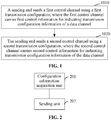
- FIG. 1 illustrates a method for sending a control channel according to an embodiment. As shown in FIG. 1 , the method according to the embodiment includes steps described below.
- a sending end sends a first control channel using a first transmission configuration, and the first control channel carries first control information for indicating transmission configuration information of a data channel.
- step 1020 the sending end sends a second control channel using a second transmission configuration, and the second control channel carries second control information for indicating transmission configuration information of the data channel.
- the first control information and the second control information may be divided according to a preset rule, for example, may be divided in modes listed in table 1.
- Table 1 Mode one Division according to importance (such as a target block error rate (BLER))
- Mode two Division according to signaling action time
- Mode three Division according to the number of signaling action links
- Mode four Division according to a size change characteristic of signaling Mode five Division according to a usage (demodulation or non-demodulation) of the signaling
- control information is sent using different control channels with different transmission configurations, so that the control information can be distinguished and thus different transmission configurations are adopted, which can improve the resource utilization rate and ensure the data transmission performance.
- the first control information and the second control information may be used for jointly indicating the same transmission configuration information or used for indicating different transmission configuration information.
- the first control channel L1 further carries third control information
- the third control information includes at least one of: pilot trigger information, feedback trigger information, BWP configuration information, transmission configuration indication (TCI) information, or configuration information of the second control channel L2.
- pilot trigger information includes at least one of: pilot trigger information, feedback trigger information, BWP configuration information, transmission configuration indication (TCI) information, or configuration information of the second control channel L2.
- TCI transmission configuration indication
- the third control information may also include other information.
- contents in the first control information belong to a same DCI format
- contents in the third control information belong to a same DCI format
- the third control information and the first control information belong to a same DCI format or respectively adopt different DCI formats.
- the second transmission configuration is determined according to at least one of the first transmission configuration or the third control information.
- the second transmission configuration includes an aggregation level selection range of the second control channel L2, transmit power of the second control channel L2, a position of the second control channel L2, a blind detection search space of the second control channel L2, an MCS of the second control channel L2, a rate matching parameter of the second control channel L2, a mapping parameter of the second control channel L2, a number of sub-blocks of the second control information carried on the second control channel L2, a number of transmission layers of the second control channel L2, a number of DMRS ports of the second control channel L2, a DMRS port allocation of the second control channel L2, a multiplexing mode of the second control channel L2 and the data channel, etc.
- the aggregation level selection range of the second control channel L2 is determined according to at least one of: an aggregation level of the first control channel, indication information carried in the third control information, or a modulation and coding scheme of the data channel.
- the aggregation level selection range of the second control channel L2 is determined according to one of the aggregation level used by the first control channel L1, the indication information carried in the third control information, or the aggregation level used by the first control channel L1 and the indication information carried in the third control information.
- the aggregation level of the first control channel L1 is associated with the aggregation level of the second control channel L2.
- the aggregation level of the second control channel L2 or a number of information bits of the second control channel L2 is less than or equal to the aggregation level of the first control channel L1 or a number of information bits of the first control channel L1.
- Mode two The aggregation level selection range of the second control channel L2 is determined according to the modulation and coding scheme of the data channel.
- the modulation and coding scheme of the data channel corresponds to the aggregation level selection range of the second control channel L2.
- whether the second control channel L2 exists or not is determined by a DCI format sent by the first control channel L1.
- control signaling for a downlink data transmission is sent through the first control channel L1 and the second control channel L2; and control signaling for an uplink data transmission is sent only through the first control channel L1, without the second control channel L2.
- It may also be determined according to a DCI format to be transmitted. For example, a DCI format 1_0 and a DCI format 0 0 are sent through the first control channel L1 and the second control channel L2, and a DCI format 1_1 and a DCI format 0_1 are sent only through the first control channel L1. This is only an example.
- Which DCI formats are sent through the first control channel L1 and which DCI formats are sent through the second control channel L2 may be configured as needed.
- the transmit power of the second control channel L2 is determined according to at least one of: transmit power of the first control channel or the indication information carried in the third control information.
- the transmit power of the second control channel L2 is determined according to the indication information carried in the third control information or the transmit power of the first control channel L1.
- control information transmit power of the first control channel L1 and control information transmit power of the second control channel L2 for example, the transmit power of the second control channel L2 is 3 decibels (dB) lower than that of the first control channel L1.
- the third control information is used for indicating an offset of power of the second control channel L2 relative to power of the first control channel L1, or indicating an offset of the power of the second control channel L2 relative to transmit power of the data channel.
- the position of the second control channel L2 (in a case where no blind detection is needed) is determined according to at least one of: a position of the first control channel, a position of the data channel, the indication information carried in the third control information, precoding granularity of the data channel, a number of transmission layers of the data channel, or a number of transmit antenna ports of the data channel.
- Mode one The position of the second control channel L2 is determined according to the position of the first control channel L1.
- the second control channel L2 is also located in a CORESET where the first control channel L1 is located.
- a time domain position of the second control channel L2 is in a t th time domain symbol after a time domain symbol where the first control channel L1 is located; where t is a natural number greater than or equal to 1 and may be agreed or configured by a base station.
- the time domain position of the second control channel L2 is in a k th time domain slot after a time domain slot where the first control channel L1 is located; where k is a natural number greater than or equal to 1 and may be agreed or configured by the base station.
- Mode two The position of the second control channel L2 is determined according to the position of the data channel.
- a frequency domain position of the second control channel L2 is on a frequency domain resource allocated by the data channel, and is discretely mapped according to a preset mapping function F.
- the second control channel L2 is located on a symbol where a demodulation pilot of the data channel is located; or the second control channel L2 is located at a position of one or more resource elements (REs) adjacent to the demodulation pilot.
- REs resource elements
- Mode three The position of the second control channel L2 is determined according to the indication information carried in the third control information.
- a higher layer pre-configures multiple CORESETs for the transmission of the second control channel L2, and the third control information indicates a selected CORESET.
- the third control information indicates whether the second control channel L2 is transmitted in a control region or a data region.
- the third control information indicates a specific position, including a frequency or time domain position, at which the second control channel L2 is transmitted in the data region.
- Mode four The position of the second control channel L2 is jointly determined by the position of the first control channel L1 and the position of the data channel.
- the second control channel L2 is located after the time domain symbol where the first control channel L1 is located and before the time domain symbol where the data channel is located.
- Mode five The position of the second control channel L2 is determined according to the precoding granularity of the data channel.
- precoding granularity of an uplink data channel will affect the number of uplink transmitted precoding matrix indicators (TPMIs) and overheads of the second control information.
- TPMIs uplink transmitted precoding matrix indicators
- the second control channel L2 cannot carry all information about the TPMIs on one CORESET, the information will be divided into multiple sub-blocks and occupy resources of multiple CORESETs.
- the number of sub-blocks required may be calculated according to the precoding granularity, a size of the CORESET, and the used aggregation level. Then, resources of corresponding CORESETs are enabled.
- These sub-blocks may have independent cyclic redundancy checks (CRCs) or a joint CRC.
- CRCs cyclic redundancy checks
- the independent CRCs may be used.
- the joint CRC may be used. Therefore, the independent CRCs or the joint CRC may be determined according to a division scheme of the first control information and the second control information.
- each sub-block may carry block serial number information corresponding to this sub-block, or a correspondence between multiple sub-blocks and CORESETs may be pre-agreed.
- a part of the sub-blocks may be transmitted within the CORESETs and a part of the sub-blocks may be transmitted on a symbol to which the data channel belongs.
- all sub-blocks are transmitted on the symbol to which the data channel belongs, which mainly depends on total overheads of the second control information.
- Mode six The position of the second control channel L2 is determined according to the number of transmission layers of the data channel.
- the second control information when the number of transmission layers is relatively small, the second control information does not need to be divided, but when the number of transmission layers is relatively large, different layers may correspond to different second control information, therefore, the second control information needs to be divided into blocks.
- these multiple parts may be transmitted on multiple CORESETs. Specific transmission positions need to be determined according to the corresponding number of transmission layers. Only one CORESET is required in a case of a small number of transmission layers, and multiple CORESETs are required in a case of a large number of transmission layers.
- a layer corresponding to each transport block may correspond to one sub-block of the second control information and correspond to one CORESET for sending.
- Mode seven The position of the second control channel L2 is determined according to the number of transmit antenna ports of the data channel.
- the second control information does not need to be divided and correspond to the transmission of one CORESET.
- the second control information needs to be divided into multiple sub-blocks, and these multiple sub-blocks correspond to the transmission of multiple CORESET, or these multiple sub-blocks are transmitted on the symbol where the data channel is located.
- the position of the second control channel may be determined according to a division rule of the first control information and the second control information. Different division rules correspond to different positions of the second control channel L2. For some division rules, the second control channel L2 and the first control channel L1 may both be located in a sending region of the control channel. In some cases, the second control channel L2 may be sent on a time domain symbol of the transmission of the data channel.
- the position of the second control channel L2 is correspondingly expanded to a set of candidate resource positions.
- the blind detection search space of the second control channel L2 (in the case where the blind detection is needed) is determined according to at least one of: the position of the first control channel, the position of the data channel, the indication information carried in the third control information, the precoding granularity of the data channel, the number of transmission layers of the data channel, or the number of transmit antenna ports of the data channel.
- the blind detection search space of the second control channel L2 is determined according to the position of the first control channel L1. For example, a time domain position of the blind detection search space of the second control channel L2 is in a t th time domain symbol after the time domain symbol where the first control channel L1 is located. For another example, the time domain position of the blind detection search space of the second control channel L2 is in the t th time domain symbol and a (t+1) th time domain symbol after the time domain symbol where the first control channel L1 is located, where t is a natural number greater than or equal to 1 and may be agreed or configured by the base station. In another example, the blind detection search space of the second control channel L2 is also located in the CORESET where the first control channel L1 is located.
- the blind detection search space of the second control channel L2 is determined according to the position of the data channel.
- frequency domain of the blind detection search space of L2 is located on the frequency domain resource allocated by the data channel and is discretely mapped according to the mapping function F.
- Mode three The blind detection search space of the second control channel L2 is determined according to the indication information carried in the third control information. For example, the higher layer pre-configures multiple CORESETs as the blind detection search space of the second control channel L2, which is dynamically selected through the third control information. For another example, the third control information indicates whether the blind detection search space of the second control channel L2 is in the control region or the data region.
- the blind detection search space of the second control channel L2 is jointly determined by the position of the first control channel L1 and the position of the data channel.
- the blind detection search space of the second control channel L2 is separated from the first control channel L1 by at least s symbols and the blind detection search space of the second control channel L2 is located on the time domain symbol where the data channel is located.
- the blind detection search space of the second control channel L2 is located after the time domain symbol where the first control channel L1 is located and before the time domain symbol where the data channel is located.
- Mode five The blind detection search space of the second control channel L2 is determined according to the precoding granularity of the data channel.
- the precoding granularity of the uplink data channel will affect the number of uplink transmitted precoding matrix indicators (TPMIs) and the overheads of the second control information.
- TPMIs uplink transmitted precoding matrix indicators
- the second control channel L2 cannot carry all information about the TPMIs on one CORESET, the information will be divided into multiple sub-blocks and occupy resources of multiple CORESETs.
- the overheads of the second control information may be determined according to the precoding granularity, so as to determine the blind detection space of the second control channel according to the size of the overheads.
- Mode six The blind detection search space of the second control channel L2 is determined according to the number of transmission layers of the data channel.
- the overheads or the number of sub-blocks of the second control information may be determined according to a pre-number of transmission layers of the data channel, so as to determine the blind detection space of the second control channel according to the size of the overheads or the number of sub-blocks.
- Mode seven The blind detection search space of the second control channel L2 is determined according to the number of transmit antenna ports of the data channel.
- the overheads or the number of sub-blocks of the second control information may be determined according to a pre-number of transmit antenna ports of the data channel, so as to determine the blind detection space of the second control channel according to the size of the overheads or the number of sub-blocks.
- the MCS of the second control channel L2 is determined according to at least one of: an aggregation level of the first control channel, the modulation and coding scheme of the data channel, the precoding granularity of the data channel, the number of transmission layers of the data channel, or the number of transmit antenna ports of the data channel.
- the MCS of the second control channel L2 is determined according to the aggregation level of the first control channel L1. For example, different aggregation levels of the first control channel L1 will determine different candidate ranges of the MCS of the second control channel L2. For example, an aggregation level 1 of the first control channel L1 corresponds to an MCS set a selectable for the second control channel L2, an aggregation level 2 of the first control channel L1 corresponds to an MCS set b selectable for the second control channel L2, and an aggregation level 4 of the first control channel L1 corresponds to an MCS set c selectable for the second control channel L2.
- aggregation levels 1 and 2 of the first control channel L1 correspond to the MCS set a selectable for the second control channel L2
- aggregation levels 4 and 8 of the first control channel L1 correspond to the MCS set b selectable for the second control channel L2.
- these are only examples, and a correspondence between the aggregation level of the first control channel L1 and the MCS of the second control channel L2 may be configured.
- the MCS of the second control channel L2 is determined according to the MCS of the data channel. For example, for downlink scheduling control signaling, there is a correspondence between the MCS of the data channel and a candidate range of the MCS of the second control channel L2, where the correspondence may be a fixed correspondence of MCS indexes, and the correspondence may be one-to-one, one-to-many, or many-to-one.
- an MCS x1 of the second control channel L2 corresponds to an MCS y1 of the data channel
- an MCS x2 of the second control channel L2 corresponds to an MCS y2 of the data channel
- the MCS x1 of the second control channel L2 corresponds to MCSs ⁇ y1, y2 ⁇ of the data channel
- the MCS x2 of the second control channel L2 corresponds to MCSs ⁇ y3, y4 ⁇ of the data channel
- MCSs ⁇ x1, x2 ⁇ of the second control channel L2 correspond to the MCS y1 of the data channel
- MCSs ⁇ x3, x4 ⁇ of the second control channel L2 correspond to the MCS y2 of the data channel.
- the size and the position of the CORESET may be dynamically adjusted.
- the resource allocation of the control channel depends on the blind detection, and in order to reduce the complexity, the resource allocation is generally not flexible enough. In this embodiment, the flexibility of the size and the position of the CORESET of the second control channel L2 will be significantly improved.
- the rate matching parameter of the second control channel L2 is determined according to at least one of: the indication information carried in the first control information or the indication information carried in the third control information.
- the first control information or the third control information will carry some indication signaling for rate matching of the second control channel L2 and the control channel, which can better avoid collisions between the control channel and other signals (such as pilots signals) and can better coordinate interference between neighboring beams, nodes or cells.
- the indication signaling may be carried in the first control information; and if the indication signaling is only used by the second control channel L2, the indication signaling may be carried in the third control information.
- the mapping parameter of the second control channel L2 is determined according to the indication information carried in the third control information.
- the mapping parameter includes RE mapping, such as a mapping mode; and the mapping parameter includes mapping from a codeword stream to a layer such as a number of layers to which the codeword stream is mapped.
- the number of sub-blocks of the second control information carried on the second control channel L2 is determined according to at least one of: the indication information carried in the third control information, a number of codewords of the data channel, the precoding granularity of the data channel, the number of transmission layers of the data channel, or the number of transmit antenna ports of the data channel.
- the number of sub-blocks of the second control information carried on the second control channel L2 is determined according to the indication information carried in the third control information.
- the second control information may include multiple sub-blocks, where the multiple sub-blocks are respectively used for different physical links; the multiple sub-blocks may also be used for multiple transmission layers of a same physical link; the multiple sub-blocks may also be used for multiple frequency domain resource sets of a same physical link; the multiple sub-blocks may also be used for multiple time domain slots of a same physical link; or the multiple sub-blocks may also be used for one of multiple physical links and multiple layers, multiple physical links and multiple slots, or multiple physical links and multiple frequency domain resource sets.
- the third control information may indicate the number of sub-blocks of the second control information, as well as the number of links, the number of layers, the number of slots, and so on, for which the sub-blocks are used.
- the number of sub-blocks of the second control information carried on the second control channel L2 is determined according to the number of codewords of the data channel.
- the second control information may include multiple sub-blocks with a number the same as the number of codewords of the data channel; or the second control information may include multiple sub-blocks with a number, which have a one-to-many correspondence with the number of codewords of the data channel.
- the number of transmission layers of the second control channel L2 or the number of DMRS ports of the second control channel L2 is determined according to at least one of: the indication information carried in the first control information or the indication information carried in the third control information.
- Mode one the number of transmission layers or the number of DMRS ports of the second control channel L2 is determined according to the indication information carried in the first control information, for example, the number of transmission layers or the number of DMRS ports is the same as the number of codeword streams of the data channel.
- Mode two the number of transmission layers or the number of DMRS ports of the second control channel L2 is determined according to the indication information carried in the third control information, and generally needs to be less than or equal to the number of DMRSs or the number of layers of the data channel.
- the DMRS port of the second control channel L2 is determined according to at least one of: the indication information carried in the first control information or the indication information carried in the third control information.
- the DMRS port of the second control channel L2 is determined according to the indication information carried in the first control information.
- a subset of DMRS ports corresponding to a codeword stream with a higher MCS of the data channel may be a port with a minimum or maximum port serial number, or a combination of multiple ports.
- the DMRS port of the second control channel L2 is determined according to the indication information carried in the third control information.
- the third control information indicates the DMRS port allocation of the second control channel L2, and may indicate one of the DMRS ports corresponding to the codeword stream with the higher MCS of the data channel.
- the multiplexing mode of the second control channel L2 and the data channel is determined according to the indication information carried in the third control information.
- the multiplexing mode includes space division, time division, frequency division, as well as time division and frequency division.
- one of a size of the second control information, a DCI format of the second control information, a BWP to which the second control information belongs, or a component carrier (CC) to which the second control information belongs is determined according to at least one of: the indication information carried in the third control information or the second control channel L2. For example, one of these is determined according to the position of the second control channel, and the corresponding size, DCI Format, belonging BWP or belonging CC may be agreed for a respective position.
- the resource of the second control channel L2 may be flexibly changed, and the size of the second control information carried on the second control channel L2 may also be indicated through the first control information, thereby avoiding the waste of overheads.
- FIG. 2 illustrates an apparatus for sending a control channel according to an embodiment.
- the apparatus includes a configuration information acquisition unit 201 and a sending unit 202.
- the configuration information acquisition unit 201 is configured to acquire a first transmission configuration and a second transmission configuration.
- the sending unit 202 is configured to send a first control channel using the first transmission configuration, and send a second control channel using the second transmission configuration; where the first control channel carries first control information for indicating transmission configuration information of a data channel; and the second control channel carries second control information for indicating transmission configuration information of the data channel.
- the first control channel further carries third control information
- the third control information includes at least one of: pilot trigger information, feedback trigger information, bandwidth part configuration information, transmission configuration indication information, or configuration information of the second control channel.
- the second transmission configuration acquired by the configuration information acquisition unit 201 is determined according to at least one of the first transmission configuration or the third control information.
- the second transmission configuration includes an aggregation level selection range of the second control channel, and the aggregation level selection range of the second control channel is determined according to at least one of: an aggregation level of the first control channel, indication information carried in the third control information, or a modulation and coding scheme of the data channel.
- the second transmission configuration includes transmit power of the second control channel, and the transmit power of the second control channel is determined according to at least one of: transmit power of the first control channel or the indication information carried in the third control information.
- the second transmission configuration includes a position of the second control channel or a blind detection search space of the second control channel, and the position or the blind detection search space of the second control channel is determined according to at least one of: a position of the first control channel, a position of the data channel, the indication information carried in the third control information, precoding granularity of the data channel, a number of transmission layers of the data channel, or the number of transmit antenna ports of the data channel.
- the second transmission configuration includes a modulation and coding scheme of the second control channel, and the modulation and coding scheme of the second control channel is determined according to at least one of: an aggregation level of the first control channel, the modulation and coding scheme of the data channel, the precoding granularity of the data channel, the number of transmission layers of the data channel, or the number of transmit antenna ports of the data channel.
- the second transmission configuration includes a rate matching parameter of the second control channel, and the rate matching parameter of the second control channel is determined according to at least one of: indication information carried in the first control information or the indication information carried in the third control information.
- the second transmission configuration includes a mapping parameter of the second control channel, and the mapping parameter of the second control channel is determined according to the indication information carried in the third control information.
- the second transmission configuration includes a number of sub-blocks of the second control information carried on the second control channel, and the number of sub-blocks of the second control information carried on the second control channel is determined according to at least one of: the indication information carried in the third control information, a number of codewords of the data channel, the precoding granularity of the data channel, the number of transmission layers of the data channel, or the number of transmit antenna ports of the data channel.
- the second transmission configuration includes a number of transmission layers of the second control channel, the number of demodulation reference signal ports of the second control channel, or a demodulation reference signal port of the second control channel, and the number of transmission layers of the second control channel, the number of demodulation reference signal ports of the second control channel, or the demodulation reference signal port of the second control channel is determined according to at least one of: the indication information carried in the first control information or the indication information carried in the third control information.
- the second transmission configuration includes a multiplexing mode of the second control channel and the data channel, and the multiplexing mode of the second control channel and the data channel is determined according to the indication information carried in the third control information.
- one of a size or a downlink control information format of the second control information, a bandwidth part to which the second control information belongs, or a component carrier to which the second control information belongs is determined according to at least one of: the indication information carried in the third control information or the position of the second control channel.
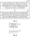
- FIG. 3 illustrates a method for detecting a control channel according to an embodiment. As shown in FIG. 3 , the method for detecting the control channel according to the embodiment includes steps described below.
- a receiving end detects a first control channel using a first transmission configuration, and acquires first control information from the first control channel, where the first control information is used for indicating transmission configuration information of a data channel.
- step 3020 the receiving end detects a second control channel using a second transmission configuration, and acquires second control information from the second control channel, where the second control information is used for indicating transmission configuration information of the data channel.
- the receiving end further acquires third control information from the first control channel, and the third control information includes at least one of: pilot trigger information, feedback trigger information, bandwidth part configuration information, transmission configuration indication information, or configuration information of the second control channel.
- the method before the receiving end detects the second control channel using the second transmission configuration, the method further includes that the receiving end determines the second transmission configuration according to at least one of the first transmission configuration or the third control information.
- the second transmission configuration includes an aggregation level selection range of the second control channel, and the aggregation level selection range of the second control channel is determined according to at least one of: an aggregation level of the first control channel, indication information carried in the third control information or a modulation and coding scheme of the data channel.
- the second transmission configuration includes a position of the second control channel or a blind detection search space of the second control channel, and the position or the blind detection search space of the second control channel is determined according to at least one of: a position of the first control channel, a position of the data channel, the indication information carried in the third control information, precoding granularity of the data channel, a number of transmission layers of the data channel, or a number of transmit antenna ports of the data channel.
- the second transmission configuration includes a modulation and coding scheme of the second control channel, and the modulation and coding scheme of the second control channel is determined according to at least one of: an aggregation level of the first control channel, the modulation and coding scheme of the data channel, the precoding granularity of the data channel, the number of transmission layers of the data channel, or the number of transmit antenna ports of the data channel.
- the second transmission configuration includes a rate matching parameter of the second control channel, and the rate matching parameter of the second control channel is determined according to at least one of: indication information carried in the first control information or the indication information carried in the third control information.
- the second transmission configuration includes a mapping parameter of the second control channel, and the mapping parameter of the second control channel is determined according to the indication information carried in the third control information.
- the second transmission configuration includes a number of sub-blocks of the second control information carried on the second control channel, and the number of sub-blocks of the second control information carried on the second control channel is determined according to at least one of: the indication information carried in the third control information, a number of codewords of the data channel, the precoding granularity of the data channel, the number of transmission layers of the data channel, or the number of transmit antenna ports of the data channel.
- the second transmission configuration includes: a number of transmission layers of the second control channel, the number of demodulation reference signal ports of the second control channel, or a demodulation reference signal port of the second control channel of the second control channel, and the number of transmission layers of the second control channel, the number of demodulation reference signal ports of the second control channel, or the demodulation reference signal port of the second control channel is determined according to at least one of: the indication information carried in the first control information or the indication information carried in the third control information.
- the second transmission configuration includes a multiplexing mode of the second control channel and the data channel, and the multiplexing mode of the second control channel and the data channel is determined according to the indication information carried in the third control information.
- one of a size of the second control information, a downlink control information format of the second control information, a bandwidth part to which the second control information belongs, or a component carrier to which the second control information belongs is determined according to at least one of: the indication information carried in the third control information or the position of the second control channel.
- FIG. 4 illustrates an apparatus for detecting a control channel according to an embodiment.
- the apparatus for detecting the control channel according to the embodiment includes a configuration information acquisition unit 401 and a detection unit 402.
- the configuration information acquisition unit 401 is configured to acquire a first transmission configuration and a second transmission configuration.
- the detection unit 402 is configured to detect a first control channel using the first transmission configuration, acquire first control information from the first control channel, detect a second control channel using the second transmission configuration, and acquire second control information from the second control channel; where the first control information indicates transmission configuration information of a data channel, and the second control information indicates transmission configuration information of the data channel.
- the configuration information acquisition unit 401 is further configured to acquire third control information from the first control channel, and the third control information includes at least one of: pilot trigger information, feedback trigger information, bandwidth part configuration information, transmission configuration indication information, or configuration information of the second control channel.
- the configuration information acquisition unit 401 is configured to acquire the second transmission configuration in a following manner: the second transmission configuration is determined according to at least one of the first transmission configuration or the third control information.
- the second transmission configuration includes at least one of: an aggregation level selection range of the second control channel, a position or a blind detection search space of the second control channel, a modulation and coding scheme of the second control channel, a rate matching parameter of the second control channel, a mapping parameter of the second control channel, the number of sub-blocks of the second control information carried on the second control channel, a number of transmission layers of the second control channel, the number of demodulation reference signal ports of the second control channel, a demodulation reference signal port of the second control channel, or a multiplexing mode of the second control channel and the data channel.
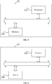
- FIG. 5 illustrates a device for sending a control channel according to an embodiment.
- the apparatus 50 for detecting a control channel according to the embodiment includes a memory 510 and a processor 520, the memory 510 stores a program which, when read and executed by the processor 520, performs following operations: sending a first control channel using a first transmission configuration, and sending a second control channel using a second transmission configuration; where the first control channel carries first control information for indicating transmission configuration information of a data channel; and the second control channel carries second control information for indicating transmission configuration information of the data channel.
- the program when read and executed by the processor 520, further implements the method for sending the control channel according to any one of the embodiments described above.
- This embodiment provides a computer-readable storage medium.
- the computer-readable storage medium stores at least one program executable by at least one processor to implement the method for sending the control channel according to any one of the embodiments described above.
- FIG. 6 illustrates a device for detecting a control channel according to an embodiment.
- the device 60 for detecting the control channel according to the embodiment includes a memory 610 and a processor 620, and the memory 610 stores a program which, when read and executed by the processor 620, implements the method for detecting the control channel according to any one of the embodiments described above.
- This embodiment provides a computer-readable storage medium.
- the computer-readable storage medium stores at least one program executable by at least one processor to implement the method for detecting the control channel according to any one of the embodiments described above.
- the computer-readable storage medium includes at least one medium capable of storing program codes, such as a USB flash disk, a read-only memory (ROM), a random access memory (RAM), a mobile hard disk, a magnetic disk or an optical disk.
- program codes such as a USB flash disk, a read-only memory (ROM), a random access memory (RAM), a mobile hard disk, a magnetic disk or an optical disk.
Landscapes
- Engineering & Computer Science (AREA)
- Signal Processing (AREA)
- Computer Networks & Wireless Communication (AREA)
- Mobile Radio Communication Systems (AREA)
Applications Claiming Priority (2)
| Application Number | Priority Date | Filing Date | Title |
|---|---|---|---|
| CN201810206077.2A CN110278059B (zh) | 2018-03-13 | 2018-03-13 | 控制信道发送、检测方法、装置及设备、存储介质 |
| PCT/CN2019/077950 WO2019174593A1 (zh) | 2018-03-13 | 2019-03-13 | 控制信道发送、检测方法、装置及设备、存储介质 |
Publications (3)
| Publication Number | Publication Date |
|---|---|
| EP3767861A1 true EP3767861A1 (de) | 2021-01-20 |
| EP3767861A4 EP3767861A4 (de) | 2021-12-08 |
| EP3767861B1 EP3767861B1 (de) | 2025-10-22 |
Family
ID=67908526
Family Applications (1)
| Application Number | Title | Priority Date | Filing Date |
|---|---|---|---|
| EP19766508.6A Active EP3767861B1 (de) | 2018-03-13 | 2019-03-13 | Steuerkanalsendeverfahren, gerät und vorrichtung, detektionsverfahren, gerät und vorrichtung sowie speichermedium |
Country Status (4)
| Country | Link |
|---|---|
| US (1) | US11412500B2 (de) |
| EP (1) | EP3767861B1 (de) |
| CN (2) | CN115001637B (de) |
| WO (1) | WO2019174593A1 (de) |
Families Citing this family (7)
| Publication number | Priority date | Publication date | Assignee | Title |
|---|---|---|---|---|
| US11533155B2 (en) * | 2019-06-07 | 2022-12-20 | Qualcomm Incorporated | Triggering demodulation reference signal bundling |
| CN114785471B (zh) | 2019-09-30 | 2025-11-28 | 中兴通讯股份有限公司 | 多点协作传输的参数确定方法及装置 |
| EP4075896B1 (de) * | 2020-01-15 | 2025-03-26 | Huawei Technologies Co., Ltd. | Datenübertragungsverfahren und -vorrichtung |
| CN115023923B (zh) | 2020-02-10 | 2023-10-24 | 高通股份有限公司 | 控制资源集预编码指示 |
| US11627568B2 (en) * | 2020-02-11 | 2023-04-11 | Qualcomm Incorporated | Control resource set for reduced-capability user equipment |
| US12328273B2 (en) * | 2020-05-13 | 2025-06-10 | Qualcomm Incorporated | Code block-based resource mapping for transmissions with data-modulated demodulation reference signals |
| CN113009849B (zh) * | 2021-02-20 | 2021-11-16 | 王功 | 一种机器人操作系统 |
Family Cites Families (18)
| Publication number | Priority date | Publication date | Assignee | Title |
|---|---|---|---|---|
| KR100958519B1 (ko) * | 2002-08-14 | 2010-05-17 | 엘지전자 주식회사 | 이동통신 시스템에서의 멀티미디어 서비스 수신 및 전송 방법 |
| US7859985B2 (en) * | 2004-03-22 | 2010-12-28 | Texas Instruments Incorporated | Control on at least one frequency selecting data carrier frequencies |
| CN101478808B (zh) * | 2009-01-21 | 2014-03-19 | 中兴通讯股份有限公司 | 一种下行控制信息的发送及检测方法 |
| CN102740372B (zh) * | 2011-04-15 | 2017-08-25 | 中兴通讯股份有限公司 | 一种下行控制信息的发送方法及装置 |
| US9455809B2 (en) * | 2011-05-25 | 2016-09-27 | Lg Electronics Inc. | Method for transceiving downlink control information in a wireless access system and apparatus therefor |
| CN102858014B (zh) * | 2011-06-30 | 2015-05-06 | 华为技术有限公司 | 控制信令的发送和接收方法及设备 |
| KR102060999B1 (ko) * | 2011-09-30 | 2019-12-31 | 삼성전자주식회사 | 제어 신호를 송신 및 수신하는 방법과 그 장치 |
| CN103891162B (zh) * | 2011-10-19 | 2017-10-03 | Lg电子株式会社 | 监测控制信道的方法和使用该方法的无线装置 |
| CN102404854B (zh) * | 2011-11-04 | 2018-04-06 | 中兴通讯股份有限公司 | 一种上行解调参考信号的资源配置方法及系统 |
| US9635658B2 (en) * | 2012-02-27 | 2017-04-25 | Samsung Electronics Co., Ltd. | Adaptation of control signaling transmissions to variations in respective resources |
| CN103312435B (zh) * | 2012-03-09 | 2016-03-02 | 华为技术有限公司 | 一种控制信道的调制或传输层数的确定方法及设备 |
| US9497756B2 (en) * | 2012-03-25 | 2016-11-15 | Comcast Cable Communications, Llc | Base station radio resource management |
| CN103857041B (zh) * | 2012-11-30 | 2017-12-05 | 华为技术有限公司 | 接收信息的方法、发送信息的方法、基站和用户设备 |
| CN105490787B (zh) * | 2014-09-15 | 2019-06-14 | 中兴通讯股份有限公司 | 下行导频的发送方法、检测方法、装置及基站、终端 |
| US10021677B2 (en) * | 2014-10-31 | 2018-07-10 | Qualcomm Incorporated | Two-stage PDCCH with DCI flag and DCI format size indicator |
| CN106712914B (zh) * | 2015-11-13 | 2021-06-04 | 北京三星通信技术研究有限公司 | 一种双工通信方法、基站及终端 |
| CN107396443B (zh) * | 2016-05-13 | 2022-07-12 | 中兴通讯股份有限公司 | 一种控制信息的发送方法、检测方法、基站和终端 |
| WO2017194022A1 (zh) * | 2016-05-13 | 2017-11-16 | 中兴通讯股份有限公司 | 下行控制信息的传输方法、装置及系统 |
-
2018
- 2018-03-13 CN CN202210420449.8A patent/CN115001637B/zh active Active
- 2018-03-13 CN CN201810206077.2A patent/CN110278059B/zh active Active
-
2019
- 2019-03-13 US US16/980,314 patent/US11412500B2/en active Active
- 2019-03-13 EP EP19766508.6A patent/EP3767861B1/de active Active
- 2019-03-13 WO PCT/CN2019/077950 patent/WO2019174593A1/zh not_active Ceased
Also Published As
| Publication number | Publication date |
|---|---|
| US20210092718A1 (en) | 2021-03-25 |
| CN110278059A (zh) | 2019-09-24 |
| CN115001637A (zh) | 2022-09-02 |
| EP3767861A4 (de) | 2021-12-08 |
| CN110278059B (zh) | 2022-05-17 |
| EP3767861B1 (de) | 2025-10-22 |
| US11412500B2 (en) | 2022-08-09 |
| WO2019174593A1 (zh) | 2019-09-19 |
| CN115001637B (zh) | 2024-09-03 |
Similar Documents
| Publication | Publication Date | Title |
|---|---|---|
| US12335976B2 (en) | Method and device for sending control channel | |
| US11412500B2 (en) | Method, apparatus and device for sending a control channel, method, apparatus and device for detecting a control channel, and storage medium | |
| US11096212B2 (en) | Data transmission method, terminal device, base station, and communications system | |
| US10448413B2 (en) | Downlink transmission method and user terminal equipment | |
| JP6489584B2 (ja) | 高次コーディングの変調処理方法及び装置、基地局、端末 | |
| EP3419237B1 (de) | Modulationsverarbeitungsverfahren und vorrichtung | |
| CN105706482B (zh) | 信道状态报告方法以及用户设备 | |
| KR102083813B1 (ko) | 업링크 제어 정보 송신 방법과 수신 방법, 및 관련 장치 | |
| CN103384183A (zh) | 一种上行控制信息传输方法及装置 | |
| KR102846298B1 (ko) | 패리티 블록을 사용한 무선 데이터 전송 | |
| KR102754280B1 (ko) | 업링크 제어 정보를 전송하는 방법, 단말 장비 및 네트워크 장비 | |
| EP3793110B1 (de) | Verfahren zur bestimmung von mcs-tabellen, endgerät und basisstation und lesbares speichermedium | |
| HK1202195B (zh) | 一种下行传输方法和用户终端设备 | |
| HK1229556B (en) | Modulation processing method and apparatus for high-order coding, base station, and terminal |
Legal Events
| Date | Code | Title | Description |
|---|---|---|---|
| STAA | Information on the status of an ep patent application or granted ep patent |
Free format text: STATUS: THE INTERNATIONAL PUBLICATION HAS BEEN MADE |
|
| PUAI | Public reference made under article 153(3) epc to a published international application that has entered the european phase |
Free format text: ORIGINAL CODE: 0009012 |
|
| STAA | Information on the status of an ep patent application or granted ep patent |
Free format text: STATUS: REQUEST FOR EXAMINATION WAS MADE |
|
| 17P | Request for examination filed |
Effective date: 20201013 |
|
| AK | Designated contracting states |
Kind code of ref document: A1 Designated state(s): AL AT BE BG CH CY CZ DE DK EE ES FI FR GB GR HR HU IE IS IT LI LT LU LV MC MK MT NL NO PL PT RO RS SE SI SK SM TR |
|
| AX | Request for extension of the european patent |
Extension state: BA ME |
|
| DAV | Request for validation of the european patent (deleted) | ||
| DAX | Request for extension of the european patent (deleted) | ||
| A4 | Supplementary search report drawn up and despatched |
Effective date: 20211110 |
|
| RIC1 | Information provided on ipc code assigned before grant |
Ipc: H04L 5/00 20060101AFI20211104BHEP |
|
| GRAP | Despatch of communication of intention to grant a patent |
Free format text: ORIGINAL CODE: EPIDOSNIGR1 |
|
| STAA | Information on the status of an ep patent application or granted ep patent |
Free format text: STATUS: GRANT OF PATENT IS INTENDED |
|
| INTG | Intention to grant announced |
Effective date: 20250707 |
|
| GRAS | Grant fee paid |
Free format text: ORIGINAL CODE: EPIDOSNIGR3 |
|
| GRAA | (expected) grant |
Free format text: ORIGINAL CODE: 0009210 |
|
| STAA | Information on the status of an ep patent application or granted ep patent |
Free format text: STATUS: THE PATENT HAS BEEN GRANTED |
|
| AK | Designated contracting states |
Kind code of ref document: B1 Designated state(s): AL AT BE BG CH CY CZ DE DK EE ES FI FR GB GR HR HU IE IS IT LI LT LU LV MC MK MT NL NO PL PT RO RS SE SI SK SM TR |
|
| REG | Reference to a national code |
Ref country code: CH Ref legal event code: F10 Free format text: ST27 STATUS EVENT CODE: U-0-0-F10-F00 (AS PROVIDED BY THE NATIONAL OFFICE) Effective date: 20251022 Ref country code: GB Ref legal event code: FG4D |
|
| REG | Reference to a national code |
Ref country code: DE Ref legal event code: R096 Ref document number: 602019077168 Country of ref document: DE |
|
| REG | Reference to a national code |
Ref country code: IE Ref legal event code: FG4D |
|
| REG | Reference to a national code |
Ref country code: NL Ref legal event code: MP Effective date: 20251022 |
|
| PG25 | Lapsed in a contracting state [announced via postgrant information from national office to epo] |
Ref country code: NL Free format text: LAPSE BECAUSE OF FAILURE TO SUBMIT A TRANSLATION OF THE DESCRIPTION OR TO PAY THE FEE WITHIN THE PRESCRIBED TIME-LIMIT Effective date: 20251022 |
|
| PGFP | Annual fee paid to national office [announced via postgrant information from national office to epo] |
Ref country code: GB Payment date: 20260128 Year of fee payment: 8 |
|
| PG25 | Lapsed in a contracting state [announced via postgrant information from national office to epo] |
Ref country code: ES Free format text: LAPSE BECAUSE OF FAILURE TO SUBMIT A TRANSLATION OF THE DESCRIPTION OR TO PAY THE FEE WITHIN THE PRESCRIBED TIME-LIMIT Effective date: 20251022 |
|
| REG | Reference to a national code |
Ref country code: LT Ref legal event code: MG9D |
|
| PG25 | Lapsed in a contracting state [announced via postgrant information from national office to epo] |
Ref country code: NO Free format text: LAPSE BECAUSE OF FAILURE TO SUBMIT A TRANSLATION OF THE DESCRIPTION OR TO PAY THE FEE WITHIN THE PRESCRIBED TIME-LIMIT Effective date: 20260122 |
|
| PGFP | Annual fee paid to national office [announced via postgrant information from national office to epo] |
Ref country code: DE Payment date: 20260114 Year of fee payment: 8 |
|
| PG25 | Lapsed in a contracting state [announced via postgrant information from national office to epo] |
Ref country code: HR Free format text: LAPSE BECAUSE OF FAILURE TO SUBMIT A TRANSLATION OF THE DESCRIPTION OR TO PAY THE FEE WITHIN THE PRESCRIBED TIME-LIMIT Effective date: 20251022 Ref country code: FI Free format text: LAPSE BECAUSE OF FAILURE TO SUBMIT A TRANSLATION OF THE DESCRIPTION OR TO PAY THE FEE WITHIN THE PRESCRIBED TIME-LIMIT Effective date: 20251022 Ref country code: AT Free format text: LAPSE BECAUSE OF FAILURE TO SUBMIT A TRANSLATION OF THE DESCRIPTION OR TO PAY THE FEE WITHIN THE PRESCRIBED TIME-LIMIT Effective date: 20251022 |
|
| REG | Reference to a national code |
Ref country code: AT Ref legal event code: MK05 Ref document number: 1850175 Country of ref document: AT Kind code of ref document: T Effective date: 20251022 |
|
| PG25 | Lapsed in a contracting state [announced via postgrant information from national office to epo] |
Ref country code: RS Free format text: LAPSE BECAUSE OF FAILURE TO SUBMIT A TRANSLATION OF THE DESCRIPTION OR TO PAY THE FEE WITHIN THE PRESCRIBED TIME-LIMIT Effective date: 20260122 |
|
| PG25 | Lapsed in a contracting state [announced via postgrant information from national office to epo] |
Ref country code: IS Free format text: LAPSE BECAUSE OF FAILURE TO SUBMIT A TRANSLATION OF THE DESCRIPTION OR TO PAY THE FEE WITHIN THE PRESCRIBED TIME-LIMIT Effective date: 20260222 |
|
| PGFP | Annual fee paid to national office [announced via postgrant information from national office to epo] |
Ref country code: FR Payment date: 20260121 Year of fee payment: 8 |
|
| PG25 | Lapsed in a contracting state [announced via postgrant information from national office to epo] |
Ref country code: PT Free format text: LAPSE BECAUSE OF FAILURE TO SUBMIT A TRANSLATION OF THE DESCRIPTION OR TO PAY THE FEE WITHIN THE PRESCRIBED TIME-LIMIT Effective date: 20260223 |
|
| PG25 | Lapsed in a contracting state [announced via postgrant information from national office to epo] |
Ref country code: PL Free format text: LAPSE BECAUSE OF FAILURE TO SUBMIT A TRANSLATION OF THE DESCRIPTION OR TO PAY THE FEE WITHIN THE PRESCRIBED TIME-LIMIT Effective date: 20251022 |
|
| PG25 | Lapsed in a contracting state [announced via postgrant information from national office to epo] |
Ref country code: LV Free format text: LAPSE BECAUSE OF FAILURE TO SUBMIT A TRANSLATION OF THE DESCRIPTION OR TO PAY THE FEE WITHIN THE PRESCRIBED TIME-LIMIT Effective date: 20251022 |