EP3767882A1 - Dispositif de surveillance de trafic de réseau - Google Patents
Dispositif de surveillance de trafic de réseau Download PDFInfo
- Publication number
- EP3767882A1 EP3767882A1 EP19186622.7A EP19186622A EP3767882A1 EP 3767882 A1 EP3767882 A1 EP 3767882A1 EP 19186622 A EP19186622 A EP 19186622A EP 3767882 A1 EP3767882 A1 EP 3767882A1
- Authority
- EP
- European Patent Office
- Prior art keywords
- network
- network traffic
- monitoring device
- data packet
- traffic monitoring
- Prior art date
- Legal status (The legal status is an assumption and is not a legal conclusion. Google has not performed a legal analysis and makes no representation as to the accuracy of the status listed.)
- Granted
Links
Images


Classifications
-
- H—ELECTRICITY
- H04—ELECTRIC COMMUNICATION TECHNIQUE
- H04L—TRANSMISSION OF DIGITAL INFORMATION, e.g. TELEGRAPHIC COMMUNICATION
- H04L41/00—Arrangements for maintenance, administration or management of data switching networks, e.g. of packet switching networks
- H04L41/24—Arrangements for maintenance, administration or management of data switching networks, e.g. of packet switching networks using dedicated network management hardware
-
- H—ELECTRICITY
- H04—ELECTRIC COMMUNICATION TECHNIQUE
- H04L—TRANSMISSION OF DIGITAL INFORMATION, e.g. TELEGRAPHIC COMMUNICATION
- H04L41/00—Arrangements for maintenance, administration or management of data switching networks, e.g. of packet switching networks
- H04L41/14—Network analysis or design
-
- H—ELECTRICITY
- H04—ELECTRIC COMMUNICATION TECHNIQUE
- H04L—TRANSMISSION OF DIGITAL INFORMATION, e.g. TELEGRAPHIC COMMUNICATION
- H04L43/00—Arrangements for monitoring or testing data switching networks
- H04L43/04—Processing captured monitoring data, e.g. for logfile generation
-
- H—ELECTRICITY
- H04—ELECTRIC COMMUNICATION TECHNIQUE
- H04L—TRANSMISSION OF DIGITAL INFORMATION, e.g. TELEGRAPHIC COMMUNICATION
- H04L43/00—Arrangements for monitoring or testing data switching networks
- H04L43/12—Network monitoring probes
-
- H—ELECTRICITY
- H04—ELECTRIC COMMUNICATION TECHNIQUE
- H04L—TRANSMISSION OF DIGITAL INFORMATION, e.g. TELEGRAPHIC COMMUNICATION
- H04L63/00—Network architectures or network communication protocols for network security
- H04L63/14—Network architectures or network communication protocols for network security for detecting or protecting against malicious traffic
- H04L63/1408—Network architectures or network communication protocols for network security for detecting or protecting against malicious traffic by monitoring network traffic
- H04L63/1416—Event detection, e.g. attack signature detection
-
- H—ELECTRICITY
- H04—ELECTRIC COMMUNICATION TECHNIQUE
- H04L—TRANSMISSION OF DIGITAL INFORMATION, e.g. TELEGRAPHIC COMMUNICATION
- H04L63/00—Network architectures or network communication protocols for network security
- H04L63/14—Network architectures or network communication protocols for network security for detecting or protecting against malicious traffic
- H04L63/1408—Network architectures or network communication protocols for network security for detecting or protecting against malicious traffic by monitoring network traffic
- H04L63/1425—Traffic logging, e.g. anomaly detection
-
- H—ELECTRICITY
- H04—ELECTRIC COMMUNICATION TECHNIQUE
- H04L—TRANSMISSION OF DIGITAL INFORMATION, e.g. TELEGRAPHIC COMMUNICATION
- H04L43/00—Arrangements for monitoring or testing data switching networks
- H04L43/10—Active monitoring, e.g. heartbeat, ping or trace-route
- H04L43/106—Active monitoring, e.g. heartbeat, ping or trace-route using time related information in packets, e.g. by adding timestamps
Definitions
- This disclosure relates to a network traffic monitoring device, in particular to such device that comprises an analysis component and a network traffic capture component.
- EP3454507A1 discloses a network tap as a hardware device which takes a copy the network traffic / frames and provides them to a monitoring device.
- the network tap has at least three ports: a first network port for connecting a first network device, a second network port for connecting a second network device and a third network port for connecting a monitoring device.
- the tap is inserted between the first network device and the second network device and allows all traffic to pass through it unimpeded in real-time, but further copies this traffic to the third network port, enabling the monitoring device to monitor this traffic.
- a network tap is preferably passive in the meaning of having the lowest impact on the monitored network devices.
- the network tap should not cause connection outage or cause performance (e.g. bit error rate) degradation.
- Network taps are commonly used for networking intrusion detection and network probes, amongst others.
- the network traffic monitoring device comprises an analysis component for analyzing one or more data packets. Further, the network traffic monitoring device comprises a network traffic capture component comprising a first network connector for receiving a first signal from a first network device.
- a first network device is a network switch, which may be the case if the network traffic monitoring device is used in a span in configuration. At least part of the first signal represents a first data packet.
- the network traffic capture component comprises hardware implemented logic, such as one or more field programmable gate arrays (FPGAs), configured to determine the first data packet based on the received first signal and provide the determined first data packet to the analysis component.
- FPGAs field programmable gate arrays
- the network traffic monitoring device comprises a second network connector for receiving a second signal from a second network device.
- the traffic monitoring device is used in line, which means that it is inserted between two network devices in order monitor the traffic between them.
- At least part of the second signal represents a second data packet.
- the hardware implemented logic is configured to determine a second data packet based on the second signal received by the second network connector from the second network device and to provide the determined second data packet to the analysis component. Further, the hardware implemented logic is configured to provide the determined first data packet to the second network connector and to provide the determined second data packet to the first network connector.
- the first network connector is configured to transmit the second data packet to the first network device and the second network connector is configured to transmit the first data packet to the second network device.
- the network traffic capture component in particular its hardware implemented logic, may be understood to capture the traffic passing through the first network device (when the first network device is a span port of a network switch for example) and/or may be understood to capture the traffic between the first network device and second network device (when the network traffic monitoring device is used as a network tap for example), because once the hardware implemented logic has determined a data packet received on the first network connector, it provides one copy of the data packet to the analysis component. When the network traffic monitoring device is used as a network tap, then the hardware implemented logic provides a data packet copy to the analysis component and one copy to the other network connector.
- the function of copying the data packets is preferably not performed by a processor, such as a central processing unit, that executes a computer program. If a malicious party has succeeded in installing a malicious computer program, then this copy function may have been compromised.
- a malicious computer program may cause such processor to alter data packets that are for example received on the first network connector from the first network device and then provide these altered data packets to the second network connector from where the altered data packets are transmitted to the second network device. In such case, the traffic between first and second network device would be compromised.
- the disclosed network traffic monitoring device does not allow for a malicious party to insert traffic into the network of which the first and second network device are part.
- the network traffic monitoring device comprises the analysis component so that the captured data packets can be analyzed at the network traffic monitoring device. This obviates the need to transmit all captured data packets to an external device for analyses and thus reduces consumed network resources, such as bandwidth.
- the analysis component may at least partially be implemented in hardware and/or at least partially in software.
- the signals received from the first and second network device may be electrical signals, for example transmitted over a conductive wire. These signals may also be optical signals, for example transmitted through an optical fiber cable.
- Determining a data packet within a signal may be understood to comprise determining a plurality of bit values based on the signal and determining which of the determined bit values represent the data packet.
- the hardware implemented logic may for example be configured to determine, based on a plurality of received bit values, which bit value is the first bit of a data packet and which bit value is the last bit of a data packet.
- the analysis component comprises one or more computer readable storage media for storing computer readable instructions.
- the analysis component further comprises a processor, preferably a microprocessor, coupled to the one or more computer readable storage media.
- the computer readable instructions when executed by the processor, cause the processor to store the first data packet and, optionally the second data packet, in the one or more computer readable storage media for analysis.
- the analysis component of the network traffic monitoring device comprises a processor and can thus be used to perform a wide variety of analyses on the captured data packets.
- the computer readable storage media may have stored any kind of computer program comprising instructions that may cause the processor to perform any type of analyses on captured packets.
- the network traffic monitoring device comprises an output coupled to the analysis component.
- the output is configured to transmit signals representing information stored in the one or more computer readable storage media to an external device.
- This embodiment allows to communicate a selection of captured data packets to an external device, for example for further analyses. Additionally or alternatively, analysis results may be transmitted to the external device.
- the output comprises a wireless module for wirelessly transmitting signals to said external device. This allows the network traffic monitoring device to wirelessly connect to the external device.
- the first network connector comprises a first ethernet physical transceiver and, optionally, the second network connector comprises a second ethernet physical transceiver.
- the ethernet physical transceiver also referred to as Ethernet PHY in the art, may be understood to be a component that operates at the physical layer of the OSI network model.
- the ethernet physical transceiver implements the Ethernet physical layer portion of the 1000BASE-T and/or 100BASE-TX, and/or 10BASE-T standards.
- the physical ethernet transceiver may be configured to convert a line modulated signal received over a wired connection with a network device to a digital signal.
- the first and second signals are optical signals.
- the first network connector comprises a first optical module for converting the first optical signal from the first network device into a first electrical signal and, optionally, the second network connector comprises a second optical module for converting the second optical signal from the second network device into a second electrical signal. This embodiment enables to capture data packets in an optical fiber network.
- the signals received from the first and, optionally second, network device convey serial data representing data packets.
- the hardware implemented logic comprises a first serial-to-parallel convertor for deserializing the first serial data and, optionally, a second serial-to-parallel convertor for deserializing the second serial data.
- the signals received from the first and, optionally second, network device represent encoded data, optionally encoded serial data.
- the hardware implemented logic comprises a physical coding sublayer (PCS) that is configured to decode the encoded data.
- PCS physical coding sublayer
- the hardware implemented logic is configured to determine meta-information associated with a data packet and provide the meta-information to the analysis component.
- the meta-information is indicative of at least one of
- the hardware implemented logic is configured to add a capture header and/or a capture trail to a data packet before providing the data packet to the analysis component.
- the capture header and/or trail may comprise meta-information associated with the packet.
- the hardware implemented logic comprises a fail-safe circuit that is configured to electrically connect the first and second network connector if the hardware implemented logic and/or the analysis component malfunctions. This embodiment enables the network traffic between the first and second network device to be maintained in case of malfunction of the network traffic monitoring device.
- the hardware implemented logic comprises a unidirectional data bus. Then, the hardware implemented logic is configured such that the determined data packets pass through the unidirectional data bus. This embodiment further safeguards that no information can flow from the analysis component to the network traffic capture component, in particular to the first and second network connectors.
- a data bus may be said to be unidirectional if it is for example controlled by a controller that is configured to control the data flow on the bus such that data packets only flow in one direction.
- the data packets may be provided to the data bus in the order in which they were received at the network connectors.
- the data bus may be a physical data bus.
- the network traffic capture component e.g. the hardware implemented logic
- the analysis component are connected to each other by means of a unidirectional bus, such as a unidirectional universal serial bus (USB).
- a unidirectional bus such as a unidirectional universal serial bus (USB).
- USB unidirectional universal serial bus
- a universal serial bus is typically controlled by a USB driver and/or by a peripheral controller. Preferably, neither of these is configured to control the operation of the universal serial bus such that it can accommodate injection of data packets from the analysis component 4.
- the network traffic capture component e.g. the hardware implemented logic
- the analysis component are connected to each other by means of a Peripheral Component Interconnect (PCI) bus and/or a Peripheral Component Interconnect Express (PCIe) bus.
- PCI Peripheral Component Interconnect
- PCIe Peripheral Component Interconnect Express
- the computer readable instructions when executed by the processor, cause the processor to select the first data packet stored in the computer readable storage media out of a plurality of stored data packets and transmit the first data packet to an external device.
- This embodiment is advantageous in that not all captured data packets are transmitted to the external device, which would requires substantial resources, such as bandwidth.
- aspects of the present invention may be embodied as a system, a method or a computer program product. Accordingly, aspects of the present invention may take the form of an entirely hardware embodiment, an entirely software embodiment (including firmware, resident software, micro-code, etc.) or an embodiment combining software and hardware aspects that may all generally be referred to herein as a "circuit,” “module” or “system.” Functions described in this disclosure may be implemented as an algorithm executed by a processor/microprocessor of a computer. Furthermore, aspects of the present invention may take the form of a computer program product embodied in one or more computer readable medium(s) having computer readable program code embodied, e.g., stored, thereon.
- the computer readable medium may be a computer readable signal medium or a computer readable storage medium.
- a computer readable storage medium may be, for example, but not limited to, an electronic, magnetic, optical, electromagnetic, infrared, or semiconductor system, apparatus, or device, or any suitable combination of the foregoing.
- a computer readable storage medium may include, but are not limited to, the following: an electrical connection having one or more wires, a portable computer diskette, a hard disk, a random access memory (RAM), a read-only memory (ROM), an erasable programmable read-only memory (EPROM or Flash memory), an optical fiber, a portable compact disc read-only memory (CD-ROM), an optical storage device, a magnetic storage device, or any suitable combination of the foregoing.
- a computer readable storage medium may be any tangible medium that can contain, or store, a program for use by or in connection with an instruction execution system, apparatus, or device.
- a computer readable signal medium may include a propagated data signal with computer readable program code embodied therein, for example, in baseband or as part of a carrier wave. Such a propagated signal may take any of a variety of forms, including, but not limited to, electro-magnetic, optical, or any suitable combination thereof.
- a computer readable signal medium may be any computer readable medium that is not a computer readable storage medium and that can communicate, propagate, or transport a program for use by or in connection with an instruction execution system, apparatus, or device.
- Program code embodied on a computer readable medium may be transmitted using any appropriate medium, including but not limited to wireless, wireline, optical fiber, cable, RF, etc., or any suitable combination of the foregoing.
- Computer program code for carrying out operations for aspects of the present invention may be written in any combination of one or more programming languages, including an object oriented programming language such as Java(TM), Smalltalk, C++ or the like and conventional procedural programming languages, such as the "C" programming language or similar programming languages.
- the program code may execute entirely on the user's computer, partly on the user's computer, as a stand-alone software package, partly on the user's computer and partly on a remote computer, or entirely on the remote computer or server.
- the remote computer may be connected to the user's computer through any type of network, including a local area network (LAN) or a wide area network (WAN), or the connection may be made to an external computer (for example, through the Internet using an Internet Service Provider).
- LAN local area network
- WAN wide area network
- Internet Service Provider an Internet Service Provider
- These computer program instructions may be provided to a processor, in particular a microprocessor or a central processing unit (CPU), of a general purpose computer, special purpose computer, or other programmable data processing apparatus to produce a machine, such that the instructions, which execute via the processor of the computer, other programmable data processing apparatus, or other devices create means for implementing the functions/acts specified in the flowchart and/or block diagram block or blocks.
- a processor in particular a microprocessor or a central processing unit (CPU), of a general purpose computer, special purpose computer, or other programmable data processing apparatus to produce a machine, such that the instructions, which execute via the processor of the computer, other programmable data processing apparatus, or other devices create means for implementing the functions/acts specified in the flowchart and/or block diagram block or blocks.
- These computer program instructions may also be stored in a computer readable medium that can direct a computer, other programmable data processing apparatus, or other devices to function in a particular manner, such that the instructions stored in the computer readable medium produce an article of manufacture including instructions which implement the function/act specified in the flowchart and/or block diagram block or blocks.
- the computer program instructions may also be loaded onto a computer, other programmable data processing apparatus, or other devices to cause a series of operational steps to be performed on the computer, other programmable apparatus or other devices to produce a computer implemented process such that the instructions which execute on the computer or other programmable apparatus provide processes for implementing the functions/acts specified in the flowchart and/or block diagram block or blocks.
- each block in the flowchart or block diagrams may represent a module, segment, or portion of code, which comprises one or more executable instructions for implementing the specified logical function(s).
- the functions noted in the blocks may occur out of the order noted in the figures. For example, two blocks shown in succession may, in fact, be executed substantially concurrently, or the blocks may sometimes be executed in the reverse order, depending upon the functionality involved.
- a computer program for carrying out the methods described herein, as well as a non-transitory computer readable storage-medium storing the computer program are provided.
- a computer program may, for example, be downloaded (updated) to the existing network traffic monitoring device or be stored upon manufacturing of such device.
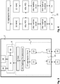
- Figure 1 shows a network traffic monitoring device 2 according to an embodiment.
- the device 2 comprises a network traffic capture component 4 and an analysis component 6.
- the traffic capture component 4 comprises a first network connector 12 that is configured to receive a first signal from first network device 16.
- Network connectors described herein may be network ports, such as Ethernet ports, that are configured to receive cabling, such as Ethernet cables, for connecting to other network devices.
- the network traffic monitoring device 2 shown in figure 1 also comprises a second network connector 14 for connecting to a second network device 18.
- This second network connector is optional.
- the network traffic monitoring device may namely be used to monitor traffic that is seen on a span port of a switch circuit. For this purpose a single network connector may be sufficient.
- Each network connector 12, 14 may be connected by means of a full duplex connection to a network device 16, 18.
- each network connector 12, 14 may comprise a receiver unit for receiving the signals from a network device and a transmitter unit for transmitting signals to a network device.
- the signals that are received on the network connectors 12 and 14 represent data packets.
- at least part of a signal received from the first network device 16 represents such a data packet and at least part of a signal received from the second network device 18 represents such a data packet.
- Network connector 12 may comprise a first ethernet physical transceiver and, optionally, the second network connector comprises a second ethernet physical transceiver.
- the network traffic capture component 4 comprises hardware implemented logic configured to determine data packets based on the signals received from the first network device 16 and second network 18 and to provide these determined first data packet to the analysis component.
- the traffic monitoring device 2 further comprises an analysis component, which may be understood to be an integrated analysis component in the sense that the traffic network monitoring device is embodied as a single unit, for example as a single box, that contains both the network traffic capture component 4 and the analysis component 6. This advantageously allows to analyze the network traffic by simply connecting it to the first and/or second network device. No additional network connector is required for connecting to an external monitoring device.
- an analysis component which may be understood to be an integrated analysis component in the sense that the traffic network monitoring device is embodied as a single unit, for example as a single box, that contains both the network traffic capture component 4 and the analysis component 6.
- the analysis component 6 can further perform packet, flow, protocol and application analysis. It may be configured to
- the analysis component 6 may comprise one or more computer readable storage media 10, such as a solid state drive (SSD). These storage media may be suitable for storing any kind of information, including one or more computer programs.
- a computer program may be understood to comprise a plurality of computer-readable instructions that can be executed by a processor 8, such as a microprocessor, of the analysis component. Such computer readable instructions may, when executed by the processor 8, cause the processor 8 to store the first and/or second data packet in the one or more computer readable storage media for analysis.
- the network traffic capture component 4, e.g. the hardware implemented logic of the network traffic capture component 4, and the analysis component 6 are connected to each other by means of a unidirectional bus 16, such as a universal serial bus (USB), which may prevent any information to travel from the analysis component 6 to the network traffic capture component 4.
- a unidirectional bus 16 such as a universal serial bus (USB)
- FIG. 2 shows in more detail an embodiment of the network traffic monitoring device 2.
- the network traffic capture component in particular the hardware implemented logic, comprises a first medium access control component 20 and a second medium access control component 22.
- the first medium access control component 20 receives the data packets that are received at network connector 12 and the second medium access control component 22 receives the data packets that are received at the network connector 14.
- the medium access control components forward the data packets to the analysis component 6.
- the arrows from network connector 12 to network connector 14 and vice versa indicate that the hardware implemented logic is configured to provide the data packets received at connector 12 to connector 14, and vice versa.
- the hardware implemented logic may comprise a scrambler component that is configured to decode the digitalized signal as output by the ethernet physical transceivers 12 and 14.
- the scrambler component may then provide the decoded signals to the medium access control components 20 and 22.
- the scrambler component may be understood to determine the data packets that are represented by signals received at the network connectors 12 and 14.
- the network traffic capture component 4 in particular the hardware implemented logic of the network traffic capture component 4, comprises a preprocessing component 24 that is configured to preprocess the data packets before providing them to the analysis component 6.
- Preprocessing a data packet may comprise determining meta-information associated with the data packet and optionally adding the meta-information in a header and/or trail of the data packet.
- the network traffic monitoring device 2 may comprise an output that is configured to transmit signals representing information stored in the one or more computer readable storage media 10 to an external device (not shown).
- the embodiment of figure 2 comprises two such outputs 28, 26.
- a first output 26 may be a network connector for physically connecting the network traffic monitoring device 2 to an external device.
- Output 26 may be an ethernet port.
- the second output 28 comprises a wireless module 28 so that the network traffic monitoring device 2 can wirelessly communicate with an external device.
- the computer readable instructions stored in the one or more storage media 10 may for example, when executed, cause the processor 8 to select out of a plurality of data packets that have been captured and subsequently been stored in the one or more computer readable storage media 10, one or more data packets and transmit the selected data packet to an external device.
- FIG. 3 shows in more detail an embodiment of the network traffic monitoring device 2.
- the traffic capture component 4 in particular the hardware implemented logic of the traffic capture component 4, comprises an aggregator block 32.
- This aggregator block receives the captured data packets from the medium access control components 20 and 22. These components may be configured to add a timestamp to each received data packet.
- the aggregator may provide the data packets received from the medium access control components 20, 22 to the preprocessor 24, which may determine further meta-information for each data packet as described herein.
- the aggregator outputs the data packets to the preprocessor 24 in accordance with the respective timestamps of the data packets.
- the aggregator receives a first data packet from component 20 at a first time instance and a second data packet, e.g. from the second component 22, thereafter, then the aggregator block 32 will first provide the first data packet to the preprocessor 24 before providing the second data packet to the preprocessor 24.
- the preprocessor 24 then feeds the data packets to a bus 34, such as a physical bus.
- a bus 34 such as a physical bus.
- the preprocessor may feed the data packets to a controller of the bus 34, such as a USB peripheral controller and/or a PCIe controller.
- a controller can be implemented in the hardware-implemented logic and/or as an external component, external to the network traffic capture component and external to the analysis component.
- the hardware-implemented logic may comprise a free running time counter.
- the time counter may be synchronized to a standard time, such as UTC or to a system time of the analysis component, for example the system time used by the processor of the analysis component.
- the analysis component in particular its processor, may be synchronized to LAN/Internet by a Network Time Protocol (NTP) and/or a Precision Time Protocol (PTP).
- NTP Network Time Protocol
- PTP Precision Time Protocol
- the free running time counter may be synchronized via a GPS receiver.
- the free running time counter may be synchronized based on an external 1PPS (1 pulse per second) signal. The purpose of the synchronization is to avoid natural time counter drifting or precisely synchronize multiple devices.
- the hardware implemented logic may thus be configured to determine meta-information associated with a data packet and provide the meta-information to the analysis component 4.
- the meta-information may be indicative of at least one of
- the hardware implemented logic may namely be configured to truncate a data packet before providing it to the analysis component 6.
- the length of the data packet changes, from the original data packet length, to a truncated data packet length.
- the hardware implemented logic comprises a fail-safe circuit 35 that is configured to electrically connect the first and second network connector if the hardware implemented logic and/or the analysis component malfunctions.
- a malfunction would be that the network traffic monitoring device 2 no longer receives power so that it cannot function properly and/or that an internal component of the hardware implemented logic fails.
- Figure shows some functional blocks that may be present in the hardware implemented logic when the signals received at the first network connector 12 and, optionally, at the second network connector 14, are optical signals. These optical signals may be received via an optical fiber cable from a network device. Such an optical fiber cable may comprise at least one optical guide for transmitting signals from the network device to the network connector and at least one other optical guide for receiving optical signals at the network connector form the network device.
- the hardware implemented logic of the network traffic capture component 4 may comprise an optical module 36a for converting the optical signal into an electrical signal. This electrical signal may then be provided to a SerDes block 38a comprised in the hardware implemented logic, which SerDes block 38a is configured to deserialize the electrical signals.
- a SerDes block 38a may further be configured to digitalize the signal, extract the clock from the signal and extracts bit values.
- Digitalizing a signal as used herein may be understood to be converting the signal into a digital form that can be processed by the hardware-implemented logic.
- digitalizing a signal comprises quantizing the signal which may be understood to be rounding sampled values of the signal to respective fixed, distinct values, such as bit values.
- the deserialized electrical signals may subsequently be provided to a physical coding sublayer (PCS) 40 comprised in the hardware implemented logic, which PCS 40a is configured to decode the electrical signal.
- PCS physical coding sublayer
- the electrical signal may have been encoded, for example at the first network device, using a 64b/66b encoding scheme, or an 8b/10b encoding scheme.
- 64b/66b encoding is typically used for 10Gbit/s ethernet
- 8b/10b encoding scheme is typically used for 1Gbit/s ethernet.
- Such encoding schemes are known in the art and are beneficial for clock recovery purposes.
- the PCS 40a may be configured to, after decoding the electrical signal, determine the data packets from the decoded signal and provide them to the medium access control component 20. However, the PCS 40 may also be configured to provide the determined data packet to another PCS 40b, that subsequently encodes the data packet again. PCS 40b may provide the encoded data packet to a SerDes block 38b, that serializes the data. The serialized data, an electrical signal, may then be provided to optical module 36b that converts the electrical signal into an optical signal again. Of course, the same operations may be performed in the other direction (from second network device to first network device) as indicated by the double arrows. In this manner, data packets are copied by the hardware implemented logic and provided to both the analysis component 6 and to the other network connector so that data packets travel unaltered between the two network devices.
- the network traffic monitoring device 2 can also comprise a fail safe circuit 35 if the received signals form the network devices are optical signals.
- the fail safe circuit 35 comprises one or more optical relay switches that are configured to guide the received optical signals directly from connector 12 to connector 14 and vice versa. Then, no conversion of the optical signals to electrical signals occurs.
- Fig. 5 depicts a block diagram illustrating an exemplary analysis component according to an embodiment.
- the analysis component 6 may include at least one processor 8 coupled to memory elements 10 through a system bus 506. As such, the analysis component may store program code within memory elements 10. Further, the processor 8 may execute the program code accessed from the memory elements 10 via a system bus 506. In one aspect, the analysis component may be implemented as a computer that is suitable for storing and/or executing program code. It should be appreciated, however, that the analysis component 6 may be implemented in the form of any system including a processor and a memory that is capable of performing the functions described within this specification.
- the memory elements 10 may include one or more physical memory components such as, for example, local memory 508 and one or more bulk storage components 510.
- the local memory may refer to random access memory or other non-persistent memory component(s) generally used during actual execution of the program code.
- a bulk storage component may be implemented as a hard drive or other persistent data storage component.
- the processing system 6 may also include one or more cache memories (not shown) that provide temporary storage of at least some program code in order to reduce the number of times program code must be retrieved from the bulk storage component 510 during execution.
- I/O components depicted as an input component 512 and an output component 514 optionally can be coupled to the analysis component.
- input components may include, but are not limited to, a keyboard, a pointing component such as a mouse, or hardware implemented logic as described herein or the like.
- output components may include, but are not limited to, a monitor or a display, speakers, or a wireless module as described herein, or the like.
- Input and/or output components may be coupled to the analysis component either directly or through intervening I/O controllers.
- the input and the output components may be implemented as a combined input/output component (illustrated in Fig. 5 with a dashed line surrounding the input component 512 and the output component 514).
- a combined input/output component is a touch sensitive display, also sometimes referred to as a "touch screen display” or simply “touch screen”.
- input to the component may be provided by a movement of a physical object, such as e.g. a stylus or a finger of a user, on or near the touch screen display.
- a network adapter 26 may also be coupled to the analysis component to enable it to become coupled to other systems, computer systems, remote network components, and/or remote storage components through intervening private or public networks.
- the network adapter may comprise a data receiver for receiving data that is transmitted by said systems, devices and/or networks to the analysis component 6, and a data transmitter for transmitting data from the analysis component 6 to said systems, devices and/or networks.
- Modems, cable modems, and Ethernet cards are examples of different types of network adapter that may be used with the analysis component 6.
- the memory elements 10 may store an application 518.
- the application 518 may be stored in the local memory 508, the one or more bulk storage components 510, or apart from the local memory and the bulk storage components.
- the analysis component 6 may further execute an operating system (not shown in Fig. 5 ) that can facilitate execution of the application 518.
- the application 518 being implemented in the form of executable program code, can be executed by the analysis component 6, e.g., by the processor 8. Responsive to executing the application, the analysis component 6 may be configured to perform one or more operations or method steps described herein.
- Various embodiments of the invention may be implemented as a program product for use with a computer system, where the program(s) of the program product define functions of the embodiments (including the methods described herein).
- the program(s) can be contained on a variety of non-transitory computer-readable storage media, where, as used herein, the expression "non-transitory computer readable storage media" comprises all computer-readable media, with the sole exception being a transitory, propagating signal.
- the program(s) can be contained on a variety of transitory computer-readable storage media.
- Illustrative computer-readable storage media include, but are not limited to: (i) non-writable storage media (e.g., read-only memory components within a computer such as CD-ROM disks readable by a CD-ROM drive, ROM chips or any type of solid-state non-volatile semiconductor memory) on which information is permanently stored; and (ii) writable storage media (e.g., flash memory, floppy disks within a diskette drive or hard-disk drive or any type of solid-state random-access semiconductor memory) on which alterable information is stored.
- the computer program may be run on the processor 8 described herein.
Landscapes
- Engineering & Computer Science (AREA)
- Computer Networks & Wireless Communication (AREA)
- Signal Processing (AREA)
- Computer Security & Cryptography (AREA)
- Computer Hardware Design (AREA)
- Computing Systems (AREA)
- General Engineering & Computer Science (AREA)
- Data Mining & Analysis (AREA)
- Data Exchanges In Wide-Area Networks (AREA)
Priority Applications (2)
| Application Number | Priority Date | Filing Date | Title |
|---|---|---|---|
| EP19186622.7A EP3767882B1 (fr) | 2019-07-16 | 2019-07-16 | Dispositif de surveillance de trafic de réseau |
| US16/522,861 US20210021622A1 (en) | 2019-07-16 | 2019-07-26 | Network traffic monitoring device |
Applications Claiming Priority (1)
| Application Number | Priority Date | Filing Date | Title |
|---|---|---|---|
| EP19186622.7A EP3767882B1 (fr) | 2019-07-16 | 2019-07-16 | Dispositif de surveillance de trafic de réseau |
Publications (3)
| Publication Number | Publication Date |
|---|---|
| EP3767882A1 true EP3767882A1 (fr) | 2021-01-20 |
| EP3767882B1 EP3767882B1 (fr) | 2023-11-01 |
| EP3767882C0 EP3767882C0 (fr) | 2023-11-01 |
Family
ID=67352493
Family Applications (1)
| Application Number | Title | Priority Date | Filing Date |
|---|---|---|---|
| EP19186622.7A Active EP3767882B1 (fr) | 2019-07-16 | 2019-07-16 | Dispositif de surveillance de trafic de réseau |
Country Status (2)
| Country | Link |
|---|---|
| US (1) | US20210021622A1 (fr) |
| EP (1) | EP3767882B1 (fr) |
Cited By (1)
| Publication number | Priority date | Publication date | Assignee | Title |
|---|---|---|---|---|
| CN115277504A (zh) * | 2022-07-11 | 2022-11-01 | 京东科技信息技术有限公司 | 一种网络流量监控方法、装置和系统 |
Families Citing this family (1)
| Publication number | Priority date | Publication date | Assignee | Title |
|---|---|---|---|---|
| US11349872B2 (en) * | 2019-11-26 | 2022-05-31 | General Electric Company | Provably secure application-specific cross-domain solutions |
Citations (3)
| Publication number | Priority date | Publication date | Assignee | Title |
|---|---|---|---|---|
| US20110211593A1 (en) * | 2009-04-08 | 2011-09-01 | Gerald Pepper | Capturing Packets With Parallel Capture Engines |
| US20140195330A1 (en) * | 2013-01-08 | 2014-07-10 | Tremor Video, Inc. | Methods and apparatus for providing effectiveness score of advertisements |
| EP3454507A1 (fr) | 2017-09-11 | 2019-03-13 | Profitap HQ B.V. | Dispositif d'écoute de réseau à adaptation d'horloge |
-
2019
- 2019-07-16 EP EP19186622.7A patent/EP3767882B1/fr active Active
- 2019-07-26 US US16/522,861 patent/US20210021622A1/en not_active Abandoned
Patent Citations (3)
| Publication number | Priority date | Publication date | Assignee | Title |
|---|---|---|---|---|
| US20110211593A1 (en) * | 2009-04-08 | 2011-09-01 | Gerald Pepper | Capturing Packets With Parallel Capture Engines |
| US20140195330A1 (en) * | 2013-01-08 | 2014-07-10 | Tremor Video, Inc. | Methods and apparatus for providing effectiveness score of advertisements |
| EP3454507A1 (fr) | 2017-09-11 | 2019-03-13 | Profitap HQ B.V. | Dispositif d'écoute de réseau à adaptation d'horloge |
Cited By (2)
| Publication number | Priority date | Publication date | Assignee | Title |
|---|---|---|---|---|
| CN115277504A (zh) * | 2022-07-11 | 2022-11-01 | 京东科技信息技术有限公司 | 一种网络流量监控方法、装置和系统 |
| CN115277504B (zh) * | 2022-07-11 | 2024-04-05 | 京东科技信息技术有限公司 | 一种网络流量监控方法、装置和系统 |
Also Published As
| Publication number | Publication date |
|---|---|
| EP3767882B1 (fr) | 2023-11-01 |
| EP3767882C0 (fr) | 2023-11-01 |
| US20210021622A1 (en) | 2021-01-21 |
Similar Documents
| Publication | Publication Date | Title |
|---|---|---|
| US20220300213A1 (en) | High Speed Data Packet Flow Processing | |
| US10237333B2 (en) | Network transfer of large files in unstable network environments | |
| CN102098227B (zh) | 报文捕获方法及内核模块 | |
| CN204089874U (zh) | 一种支持报文存储的交换机 | |
| US11681470B2 (en) | High-speed replay of captured data packets | |
| US20120191802A1 (en) | Method and apparatus of performing remote computer file exchange | |
| US9252812B2 (en) | Low latency serial data encoding scheme for enhanced burst error immunity and long term reliability | |
| CN108011850B (zh) | 数据包的重组方法及装置、计算机设备及可读介质 | |
| JP4170299B2 (ja) | 通信状態遷移モニタ方法及びこれを利用した通信状態遷移モニタ装置 | |
| EP3767882B1 (fr) | Dispositif de surveillance de trafic de réseau | |
| CN104780019A (zh) | 光纤通信数据的存储方法 | |
| KR102230236B1 (ko) | SerDes 링크 파라미터 디버깅 방법, 장치 및 컴퓨터 기억매체 | |
| CN108460044A (zh) | 数据的处理方法和装置 | |
| CN120238474A (zh) | 一种链路协议分析方法、网络芯片及计算设备 | |
| US8331270B2 (en) | In-band communication of network statistics over a FICON network | |
| US12591526B2 (en) | Allowing non-volatile memory express (NVMe) over fabric (NVMe-oF) traffic over interfaces using a scalable end point (SEP) addressing mechanism | |
| US10623338B2 (en) | Information processing device, information processing method and non-transitory computer-readable storage medium | |
| US10892971B2 (en) | System and method for network communication monitoring | |
| CN104378438B (zh) | 数据同步方法及其装置 | |
| CN116614481A (zh) | 一种多媒体数据传输方法、装置、设备及存储介质 | |
| CN117240750B (zh) | 一种交换机端口的监控方法、装置、交换机、设备及介质 | |
| US20260122322A1 (en) | Routing of enhanced video streams through legacy filtering appliances | |
| Zabołotny | Optimized Ethernet transmission of acquired data from FPGA to embedded system | |
| EP4736463A1 (fr) | Routage de vidéo plein mouvement (fmv) dans des systèmes de transfert unidirectionnel | |
| CN118233205A (zh) | 一种协议隔离系统及其数据传输方法 |
Legal Events
| Date | Code | Title | Description |
|---|---|---|---|
| PUAI | Public reference made under article 153(3) epc to a published international application that has entered the european phase |
Free format text: ORIGINAL CODE: 0009012 |
|
| STAA | Information on the status of an ep patent application or granted ep patent |
Free format text: STATUS: THE APPLICATION HAS BEEN PUBLISHED |
|
| AK | Designated contracting states |
Kind code of ref document: A1 Designated state(s): AL AT BE BG CH CY CZ DE DK EE ES FI FR GB GR HR HU IE IS IT LI LT LU LV MC MK MT NL NO PL PT RO RS SE SI SK SM TR |
|
| AX | Request for extension of the european patent |
Extension state: BA ME |
|
| STAA | Information on the status of an ep patent application or granted ep patent |
Free format text: STATUS: REQUEST FOR EXAMINATION WAS MADE |
|
| 17P | Request for examination filed |
Effective date: 20210708 |
|
| RBV | Designated contracting states (corrected) |
Designated state(s): AL AT BE BG CH CY CZ DE DK EE ES FI FR GB GR HR HU IE IS IT LI LT LU LV MC MK MT NL NO PL PT RO RS SE SI SK SM TR |
|
| STAA | Information on the status of an ep patent application or granted ep patent |
Free format text: STATUS: EXAMINATION IS IN PROGRESS |
|
| 17Q | First examination report despatched |
Effective date: 20220504 |
|
| REG | Reference to a national code |
Ref legal event code: R079 Free format text: PREVIOUS MAIN CLASS: H04L0012240000 Ipc: H04L0041140000 Ref country code: DE Ref document number: 602019040427 Country of ref document: DE |
|
| GRAP | Despatch of communication of intention to grant a patent |
Free format text: ORIGINAL CODE: EPIDOSNIGR1 |
|
| STAA | Information on the status of an ep patent application or granted ep patent |
Free format text: STATUS: GRANT OF PATENT IS INTENDED |
|
| INTG | Intention to grant announced |
Effective date: 20230526 |
|
| RIC1 | Information provided on ipc code assigned before grant |
Ipc: H04L 43/12 20220101ALI20230512BHEP Ipc: H04L 43/106 20220101ALI20230512BHEP Ipc: H04L 43/04 20220101ALI20230512BHEP Ipc: H04L 41/14 20220101AFI20230512BHEP |
|
| GRAS | Grant fee paid |
Free format text: ORIGINAL CODE: EPIDOSNIGR3 |
|
| GRAA | (expected) grant |
Free format text: ORIGINAL CODE: 0009210 |
|
| STAA | Information on the status of an ep patent application or granted ep patent |
Free format text: STATUS: THE PATENT HAS BEEN GRANTED |
|
| AK | Designated contracting states |
Kind code of ref document: B1 Designated state(s): AL AT BE BG CH CY CZ DE DK EE ES FI FR GB GR HR HU IE IS IT LI LT LU LV MC MK MT NL NO PL PT RO RS SE SI SK SM TR |
|
| REG | Reference to a national code |
Ref country code: GB Ref legal event code: FG4D |
|
| REG | Reference to a national code |
Ref country code: CH Ref legal event code: EP |
|
| REG | Reference to a national code |
Ref country code: DE Ref legal event code: R096 Ref document number: 602019040427 Country of ref document: DE |
|
| REG | Reference to a national code |
Ref country code: IE Ref legal event code: FG4D |
|
| U01 | Request for unitary effect filed |
Effective date: 20231201 |
|
| U07 | Unitary effect registered |
Designated state(s): AT BE BG DE DK EE FI FR IT LT LU LV MT NL PT SE SI Effective date: 20231207 |
|
| RAP4 | Party data changed (patent owner data changed or rights of a patent transferred) |
Owner name: PROFITAP HQ B.V. |
|
| U1H | Name or address of the proprietor changed after the registration of the unitary effect |
Owner name: PROFITAP HQ B.V.; NL |
|
| PG25 | Lapsed in a contracting state [announced via postgrant information from national office to epo] |
Ref country code: GR Free format text: LAPSE BECAUSE OF FAILURE TO SUBMIT A TRANSLATION OF THE DESCRIPTION OR TO PAY THE FEE WITHIN THE PRESCRIBED TIME-LIMIT Effective date: 20240202 |
|
| PG25 | Lapsed in a contracting state [announced via postgrant information from national office to epo] |
Ref country code: IS Free format text: LAPSE BECAUSE OF FAILURE TO SUBMIT A TRANSLATION OF THE DESCRIPTION OR TO PAY THE FEE WITHIN THE PRESCRIBED TIME-LIMIT Effective date: 20240301 |
|
| PG25 | Lapsed in a contracting state [announced via postgrant information from national office to epo] |
Ref country code: ES Free format text: LAPSE BECAUSE OF FAILURE TO SUBMIT A TRANSLATION OF THE DESCRIPTION OR TO PAY THE FEE WITHIN THE PRESCRIBED TIME-LIMIT Effective date: 20231101 |
|
| PG25 | Lapsed in a contracting state [announced via postgrant information from national office to epo] |
Ref country code: IS Free format text: LAPSE BECAUSE OF FAILURE TO SUBMIT A TRANSLATION OF THE DESCRIPTION OR TO PAY THE FEE WITHIN THE PRESCRIBED TIME-LIMIT Effective date: 20240301 Ref country code: GR Free format text: LAPSE BECAUSE OF FAILURE TO SUBMIT A TRANSLATION OF THE DESCRIPTION OR TO PAY THE FEE WITHIN THE PRESCRIBED TIME-LIMIT Effective date: 20240202 Ref country code: ES Free format text: LAPSE BECAUSE OF FAILURE TO SUBMIT A TRANSLATION OF THE DESCRIPTION OR TO PAY THE FEE WITHIN THE PRESCRIBED TIME-LIMIT Effective date: 20231101 |
|
| PG25 | Lapsed in a contracting state [announced via postgrant information from national office to epo] |
Ref country code: RS Free format text: LAPSE BECAUSE OF FAILURE TO SUBMIT A TRANSLATION OF THE DESCRIPTION OR TO PAY THE FEE WITHIN THE PRESCRIBED TIME-LIMIT Effective date: 20231101 Ref country code: PL Free format text: LAPSE BECAUSE OF FAILURE TO SUBMIT A TRANSLATION OF THE DESCRIPTION OR TO PAY THE FEE WITHIN THE PRESCRIBED TIME-LIMIT Effective date: 20231101 Ref country code: NO Free format text: LAPSE BECAUSE OF FAILURE TO SUBMIT A TRANSLATION OF THE DESCRIPTION OR TO PAY THE FEE WITHIN THE PRESCRIBED TIME-LIMIT Effective date: 20240201 Ref country code: HR Free format text: LAPSE BECAUSE OF FAILURE TO SUBMIT A TRANSLATION OF THE DESCRIPTION OR TO PAY THE FEE WITHIN THE PRESCRIBED TIME-LIMIT Effective date: 20231101 |
|
| PG25 | Lapsed in a contracting state [announced via postgrant information from national office to epo] |
Ref country code: CZ Free format text: LAPSE BECAUSE OF FAILURE TO SUBMIT A TRANSLATION OF THE DESCRIPTION OR TO PAY THE FEE WITHIN THE PRESCRIBED TIME-LIMIT Effective date: 20231101 |
|
| PG25 | Lapsed in a contracting state [announced via postgrant information from national office to epo] |
Ref country code: SK Free format text: LAPSE BECAUSE OF FAILURE TO SUBMIT A TRANSLATION OF THE DESCRIPTION OR TO PAY THE FEE WITHIN THE PRESCRIBED TIME-LIMIT Effective date: 20231101 |
|
| PG25 | Lapsed in a contracting state [announced via postgrant information from national office to epo] |
Ref country code: SM Free format text: LAPSE BECAUSE OF FAILURE TO SUBMIT A TRANSLATION OF THE DESCRIPTION OR TO PAY THE FEE WITHIN THE PRESCRIBED TIME-LIMIT Effective date: 20231101 Ref country code: SK Free format text: LAPSE BECAUSE OF FAILURE TO SUBMIT A TRANSLATION OF THE DESCRIPTION OR TO PAY THE FEE WITHIN THE PRESCRIBED TIME-LIMIT Effective date: 20231101 Ref country code: CZ Free format text: LAPSE BECAUSE OF FAILURE TO SUBMIT A TRANSLATION OF THE DESCRIPTION OR TO PAY THE FEE WITHIN THE PRESCRIBED TIME-LIMIT Effective date: 20231101 |
|
| REG | Reference to a national code |
Ref country code: DE Ref legal event code: R097 Ref document number: 602019040427 Country of ref document: DE |
|
| U20 | Renewal fee for the european patent with unitary effect paid |
Year of fee payment: 6 Effective date: 20240729 |
|
| PLBE | No opposition filed within time limit |
Free format text: ORIGINAL CODE: 0009261 |
|
| STAA | Information on the status of an ep patent application or granted ep patent |
Free format text: STATUS: NO OPPOSITION FILED WITHIN TIME LIMIT |
|
| 26N | No opposition filed |
Effective date: 20240802 |
|
| PG25 | Lapsed in a contracting state [announced via postgrant information from national office to epo] |
Ref country code: MC Free format text: LAPSE BECAUSE OF FAILURE TO SUBMIT A TRANSLATION OF THE DESCRIPTION OR TO PAY THE FEE WITHIN THE PRESCRIBED TIME-LIMIT Effective date: 20231101 |
|
| REG | Reference to a national code |
Ref country code: CH Ref legal event code: PL |
|
| PG25 | Lapsed in a contracting state [announced via postgrant information from national office to epo] |
Ref country code: CH Free format text: LAPSE BECAUSE OF NON-PAYMENT OF DUE FEES Effective date: 20240731 |
|
| PG25 | Lapsed in a contracting state [announced via postgrant information from national office to epo] |
Ref country code: IE Free format text: LAPSE BECAUSE OF NON-PAYMENT OF DUE FEES Effective date: 20240716 |
|
| U20 | Renewal fee for the european patent with unitary effect paid |
Year of fee payment: 7 Effective date: 20250728 |
|
| PGFP | Annual fee paid to national office [announced via postgrant information from national office to epo] |
Ref country code: GB Payment date: 20250728 Year of fee payment: 7 |
|
| PG25 | Lapsed in a contracting state [announced via postgrant information from national office to epo] |
Ref country code: RO Free format text: LAPSE BECAUSE OF FAILURE TO SUBMIT A TRANSLATION OF THE DESCRIPTION OR TO PAY THE FEE WITHIN THE PRESCRIBED TIME-LIMIT Effective date: 20231101 |
|
| PG25 | Lapsed in a contracting state [announced via postgrant information from national office to epo] |
Ref country code: CY Free format text: LAPSE BECAUSE OF FAILURE TO SUBMIT A TRANSLATION OF THE DESCRIPTION OR TO PAY THE FEE WITHIN THE PRESCRIBED TIME-LIMIT; INVALID AB INITIO Effective date: 20190716 |
|
| PG25 | Lapsed in a contracting state [announced via postgrant information from national office to epo] |
Ref country code: HU Free format text: LAPSE BECAUSE OF FAILURE TO SUBMIT A TRANSLATION OF THE DESCRIPTION OR TO PAY THE FEE WITHIN THE PRESCRIBED TIME-LIMIT; INVALID AB INITIO Effective date: 20190716 |