EP3768004B1 - Procédé et appareil d'émission et de réception d'informations - Google Patents
Procédé et appareil d'émission et de réception d'informations Download PDFInfo
- Publication number
- EP3768004B1 EP3768004B1 EP18913862.1A EP18913862A EP3768004B1 EP 3768004 B1 EP3768004 B1 EP 3768004B1 EP 18913862 A EP18913862 A EP 18913862A EP 3768004 B1 EP3768004 B1 EP 3768004B1
- Authority
- EP
- European Patent Office
- Prior art keywords
- downlink
- terminal device
- channel quality
- repetitions
- carrier
- Prior art date
- Legal status (The legal status is an assumption and is not a legal conclusion. Google has not performed a legal analysis and makes no representation as to the accuracy of the status listed.)
- Active
Links
Images





Classifications
-
- H—ELECTRICITY
- H04—ELECTRIC COMMUNICATION TECHNIQUE
- H04L—TRANSMISSION OF DIGITAL INFORMATION, e.g. TELEGRAPHIC COMMUNICATION
- H04L1/00—Arrangements for detecting or preventing errors in the information received
- H04L1/08—Arrangements for detecting or preventing errors in the information received by repeating transmission, e.g. Verdan system
-
- H—ELECTRICITY
- H04—ELECTRIC COMMUNICATION TECHNIQUE
- H04L—TRANSMISSION OF DIGITAL INFORMATION, e.g. TELEGRAPHIC COMMUNICATION
- H04L1/00—Arrangements for detecting or preventing errors in the information received
- H04L1/0001—Systems modifying transmission characteristics according to link quality, e.g. power backoff
- H04L1/0023—Systems modifying transmission characteristics according to link quality, e.g. power backoff characterised by the signalling
- H04L1/0026—Transmission of channel quality indication
-
- H—ELECTRICITY
- H04—ELECTRIC COMMUNICATION TECHNIQUE
- H04L—TRANSMISSION OF DIGITAL INFORMATION, e.g. TELEGRAPHIC COMMUNICATION
- H04L1/00—Arrangements for detecting or preventing errors in the information received
- H04L1/0001—Systems modifying transmission characteristics according to link quality, e.g. power backoff
- H04L1/0023—Systems modifying transmission characteristics according to link quality, e.g. power backoff characterised by the signalling
- H04L1/0028—Formatting
- H04L1/0029—Reduction of the amount of signalling, e.g. retention of useful signalling or differential signalling
-
- H—ELECTRICITY
- H04—ELECTRIC COMMUNICATION TECHNIQUE
- H04L—TRANSMISSION OF DIGITAL INFORMATION, e.g. TELEGRAPHIC COMMUNICATION
- H04L1/00—Arrangements for detecting or preventing errors in the information received
- H04L1/12—Arrangements for detecting or preventing errors in the information received by using return channel
- H04L1/16—Arrangements for detecting or preventing errors in the information received by using return channel in which the return channel carries supervisory signals, e.g. repetition request signals
- H04L1/18—Automatic repetition systems, e.g. Van Duuren systems
- H04L1/1867—Arrangements specially adapted for the transmitter end
- H04L1/189—Transmission or retransmission of more than one copy of a message
-
- H—ELECTRICITY
- H04—ELECTRIC COMMUNICATION TECHNIQUE
- H04W—WIRELESS COMMUNICATION NETWORKS
- H04W24/00—Supervisory, monitoring or testing arrangements
- H04W24/10—Scheduling measurement reports ; Arrangements for measurement reports
-
- H—ELECTRICITY
- H04—ELECTRIC COMMUNICATION TECHNIQUE
- H04W—WIRELESS COMMUNICATION NETWORKS
- H04W56/00—Synchronisation arrangements
-
- H—ELECTRICITY
- H04—ELECTRIC COMMUNICATION TECHNIQUE
- H04W—WIRELESS COMMUNICATION NETWORKS
- H04W74/00—Wireless channel access
- H04W74/08—Non-scheduled access, e.g. ALOHA
- H04W74/0833—Random access procedures, e.g. with 4-step access
Definitions
- This disclosure relates to the field of mobile communications technologies, and in particular, to an information sending method, an information receiving method, and an apparatus.
- NB-IoT narrowband internet of things
- LTE long term evolution
- the NB-IoT system needs to support a very large coverage area, and a base station may use completely different scheduling policies for user equipments (user equipment, UE) in different communication environments.
- UE user equipment
- UEs with different channel conditions need to be differentiated, to facilitate scheduling by the base station. Therefore, a concept of coverage level is introduced into the NB-IoT system.
- UEs at a same coverage level have similar channel transmission conditions
- the base station may use similar scheduling parameters for the UEs, and these UEs have similar control signaling overheads.
- a coverage level is defined as follows:
- a base station provides, in system information, a reference signal received power (reference signal receiving power, RSRP) decision threshold for differentiating between coverage levels.
- the RSRP decision threshold is mainly determined by the base station based on an uplink interference status.
- UE determines, based on the RSRP decision threshold, a coverage level at which the UE is located, and selects a random access resource corresponding to the coverage level during random access.
- the base station When performing scheduling for a terminal device, the base station performs scheduling based on a resource corresponding to a coverage level at which the terminal device is located.
- the base station cannot obtain more information, and can use only the uplink interference status as a reference. Therefore, currently, the RSRP decision threshold is determined by the base station merely based on the uplink interference status. The RSRP decision threshold determined in this manner may be inaccurate, and consequently a coverage level determined by UE is also inaccurate. Therefore, the base station needs more information when performing scheduling for the terminal device.
- bitmap with greater than 2 bits to provide higher granularity than CE levels 0, 1, and 2 in current RA procedure and higher granularity can be used for link adaptation as early as Msg4.
- This document provides an explicit example for NB-IoT standalone deployment scenario for NDCCH of idle paging UE with a 3-bit mapping for NPDCCH repetitions with Rmax being up to 2048 with at most 8 candidates. Different values are provided for NPDCCH with corresponding values for SNR for the Mapping of SINR and NPDCCH repetitions for idle paging UE on certain type of Common Search Space.
- Document WO 2019/151819 A1 discloses a method for CSI reporting at a UE and the corresponding UE, and relates to a communication method and system for converging a 5th-Generation (5G) communication system for supporting higher data rates beyond a 4th-Generation (4G) system with a technology for Internet of Things (IoT).
- 5G 5th-Generation
- 4G 4th-Generation
- IoT Internet of Things
- the disclosure of this document may be applied to intelligent services based on the 5G communication technology and the IoT-related technology, such as smart home, smart building, smart city, smart car, connected car, health care, digital education, smart retail, security and safety services.
- a Cell index field can be added inRAR to further distinguish the same preamble of different carriers. It is also possible to use different RA-RNTI to distinguish the same preamble of different carriers.
- ERICSSON provides in "NB-loT - Remaining issues for NPDSCH design", XP051080718, gap configuration details format and channel multiplexing aspects regarding NB-PDCCH. This document describes some proposals, for instance that two sets of gap configurations are defined for NB-loT downlink transmission, for each configuration, the cycle starts with transmission period followed by the subframes for the gaps, and suggests some concrete realizations for gap starting point periodicity and gap size.
- a communications system based on an existing cellular network infrastructure is an important type of MTC communications system.
- This type of MTC communication is usually referred to as cellular MTC or cellular IoT (referred to as CIoT for short).
- the 3rd generation partnership project (3rd generation partnership project, 3GPP) standardization organization has been paying close attention to development of cellular MTC and has actively carried out standardization of related technologies.
- 3rd generation partnership project, 3GPP 3rd generation partnership project, 3GPP
- 3GPP 3rd generation partnership project
- a cellular MTC service mainly has the following requirements on a network and UE: Requirement for a large coverage area:
- Currently available MTC services usually do not require a very high service rate, but need to be able to support a very large coverage area.
- the so-called large coverage area means that an MTC base station uses a relatively strong coverage enhancement technology, and a communications service is available to user equipment when a penetration loss is relatively high (20 dB).
- a communications service is available to user equipment when a penetration loss is relatively high (20 dB).
- user equipments in smart household and intelligent meter reading services for example, a smart water meter and a smart electricity meter, are usually installed indoors or even in a basement.
- An existing cellular network technology can hardly provide a reliable communications service for devices at these locations, but an MTC base station needs to provide a stable connection service for such devices.
- An MTC base station may serve a large quantity (exceeding tens of thousands or even hundreds of thousands) of internet of things terminal devices such as smart water/electricity meters, smart community devices, monitoring devices, vehicles, and wearable devices that are deployed on a large scale, far exceeding a currently supported quantity of mobile terminals. How to simultaneously provide a connection service to such a massive quantity of terminal devices without causing network congestion is a problem that needs to be resolved.
- Low power consumption Because of diversified actual application and various deployment environments of MTC terminal devices, the MTC terminal devices are usually powered by using batteries. However, replacing batteries for such a massive quantity of devices consumes enormous manpower costs and time costs. Therefore, functional components of an MTC device usually need to have an extremely low power consumption level, so that the device can have a longer standby time, thereby reducing a quantity of times of battery replacement.
- NB-IoT Currently, the 3GPP standard is conducting research on how to fully leverage characteristics of a narrowband technology by designing a new air interface based on a cellular network to carry an IoT service. Such an IoT is referred to as an NB-IoT. Compared with those in a conventional cellular network, services and terminal devices in an NB-IoT system have the following characteristics:
- the NB-IoT system has many specific designs.
- the NB-IoT system does not use PUCCHs, to simplify the terminal devices and reduce costs.
- a control channel such as a narrowband physical downlink control channel (narrow physical downlink control channel, NPDCCH)
- a data channel such as a narrowband physical downlink shared channel (narrow physical downlink shared channel, NPDSCH) or a narrowband physical uplink shared channel (narrow physical uplink shared channel, NPDSCH) of the NB-IoT system use a manner of repeated sending, in which same content is sent repeatedly for hundreds of times, to improve a possibility that a terminal device with relatively poor coverage receives the content successfully.
- Random access procedure is a procedure that starts when a terminal device sends a random access preamble (preamble) to start to attempt to access a network, until a basic signaling connection with a network device is set up. Random access is a key step in a mobile communications system, and is also the last step by which the terminal device establishes a communications link with the network device. For example, the terminal device exchanges information with the network device in the random access procedure, to complete a subsequent operation such as calling, resource requesting, or data transmission. In addition, the terminal device may further implement uplink time synchronization with the system through random access.
- Random access procedures may be classified into a contention-based random access procedure and a contention-free random access procedure.
- the implementations of this disclosure are mainly described by using the contention-based random access procedure as an example.
- an Rmax parameter is also configured for the anchor carrier by using a SIB2.
- Rmax represents a maximum number of repetitions, of a downlink control channel carried on the anchor carrier, in common search space in which the downlink control channel is located; and therefore has a meaning similar to that of Rmax in the non-anchor carrier.
- FIG. 1 is an example.
- a terminal device selects an NPRACH resource on an uplink non-anchor carrier 1 for sending an MSG1, and a SIB22 indicates that a downlink carrier corresponding to the uplink non-anchor carrier 1 is a downlink non-anchor carrier 1.
- a coverage level is defined as follows:
- a base station provides, in system information, an RSRP decision threshold for differentiating between coverage levels.
- the RSRP decision threshold is mainly determined by the base station based on an uplink interference status.
- a preamble (preamble) sequence of an MSG1 sent by a terminal device is detected by the base station in a preset probability.
- an NB-IoT terminal device determines its coverage level according to the following process:
- a base station sets an RSRP decision threshold based on an uplink interference status, mainly considering that performance of receiving an uplink NPRACH preamble should be ensured as far as possible.
- an interference level of uplink receiving of a base station is different from a downlink interference level of a terminal device. If an RSRP decision threshold is determined based on only an uplink interference status, the determined RSRP decision threshold may be inaccurate.
- the base station determines the RSRP decision threshold based on the uplink interference status. For example, uplink interference may be relatively high, and the base station sets the RSRP decision threshold to a relatively large value.
- the base station also performs downlink scheduling for these terminal devices based on NPRACH resources corresponding to the coverage levels at which these terminal devices are located.
- uplink interference may be relatively low, and the base station sets the RSRP decision threshold to a relatively small value.
- most terminal devices each may be located at a level with good coverage and send a preamble for a relatively small quantity of times.
- downlink interference of some terminal devices may be relatively high, but these terminal devices each are located at a level with good coverage.
- the base station also performs downlink scheduling for these terminal devices based on NPRACH resources corresponding to the coverage levels at which these terminal devices are located. As a result, a quantity of downlink retransmissions is also relatively small, causing a failure in downlink receiving.
- a base station performs uplink and downlink scheduling for a terminal device based on only a coverage level at which the terminal device is located, so that a scheduling result is inaccurate.
- a network device when performing scheduling for a terminal device, in addition to considering a coverage level at which the terminal device is located, a network device may further consider conditions such as downlink channel quality of the terminal device, so that the network device can perform scheduling for the terminal device in a more proper manner. This helps reduce waste of resources and improve resource utilization.
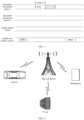
- FIG. 2 is a schematic diagram of an application scenario according to an implementation of this disclosure.
- FIG. 2 shows a network device and a plurality of terminal devices.
- These terminal devices are terminal devices in an NB-IoT system, and include a refrigerator, a vehicle, a TV set, and the like.
- the network device is an access network device such as a base station.
- the network device and the at least one terminal device shown in FIG. 2 may be configured to implement the technical solutions provided in the implementations of this disclosure.
- An implementation of this disclosure provides an information sending and receiving method.
- a terminal device may send downlink channel quality information to a network device by using an MSG3 in a random access procedure.
- the network device may further consider a downlink channel quality status, so that an ultimately determined RSRP decision threshold is more accurate.
- FIG. 3 is a flowchart of a first information sending and receiving method according to an implementation of this disclosure.
- a terminal device generates a downlink channel quality report volume, where the downlink channel quality report volume is used to indicate a relative relationship between a first number of repetitions and a second number of repetitions, the first number of repetitions is a quantity of retransmissions that need to be performed in a preset downlink control channel format to achieve a preset block error rate, and the second number of repetitions is a number of repetitions corresponding to common search space of a downlink control channel carried on a downlink carrier.
- the second number of repetitions may also be construed as a number of repetitions, corresponding to the downlink control channel carried on the downlink carrier, in the common search space of the downlink control channel.
- the terminal device needs to obtain the first number of repetitions and the second number of repetitions. How the terminal device obtains the first number of repetitions is described first.
- Table 3 Attribute (Attribute) Downlink channel quality (Downlink channel quality) Downlink control information (DCI) format (format) Format N1 Format N1 Quantity of information bits (Number of information bits) 23 bits 23 bits System bandwidth (System Bandwidth) 200 kHz 200 kHz Antenna configuration (Antenna configuration) 2x1 2x1 Aggregation level (Aggregation level) 2 2 Discontinuous reception (discontinuous reception, DRX) Off (OFF) OFF
- the terminal device may measure a downlink SINR, and query the preset mapping relationship after obtaining the SINR, to determine a number of repetitions corresponding to the SINR.
- the terminal device may obtain the first number of repetitions by performing measurement on different carriers.
- the terminal device Before sending an MSG1 in a random access procedure, that is, before the random access procedure starts, the terminal device may perform measurement on a downlink anchor carrier, to obtain the first number of repetitions. For example, before sending the MSG1 in the random access procedure, the terminal device measures an SINR of the downlink anchor carrier. For example, the SINR is referred to as a first SINR. In this case, the terminal device determines the first number of repetitions based on the SINR of the anchor carrier. Specifically, before sending the MSG1 in the random access procedure, the terminal device performs measurement on the downlink anchor carrier by using a reference signal. For example, the reference signal is an NRS.
- the reference signal is an NRS.
- the terminal device Before sending the MSG1, the terminal device receives the NRS on the downlink anchor carrier, performs measurement based on the NRS to obtain the first SINR, and then can determine the first number of repetitions based on the SINR and the preset mapping relationship.
- the terminal device may perform measurement on a downlink carrier on which an MSG2 in the random access procedure is located, that is, a downlink carrier for sending the MSG2 in the random access procedure, to obtain the first number of repetitions.
- the terminal device sends the MSG1 by using a selected random access resource.
- the random access resource is, for example, an NPRACH resource.
- the terminal device Before sending the MSG1, the terminal device first needs to select an NPRACH resource. For example, the terminal device selects, based on configurations in a SIB2 and a SIB22 in a preset probability, an uplink carrier for sending the MSG1.
- the terminal device can determine, based on the configuration in the SIB2 or the SIB22, a downlink carrier corresponding to the uplink carrier, that is, determine the downlink carrier on which the MSG2 is located. For example, after sending the MSG1 in the random access procedure, the terminal device measures an SINR of the downlink carrier on which the MSG2 is located. For example, the SINR is referred to as a second SINR. In this case, the terminal device can obtain the first number of repetitions based on the second SINR. Specifically, after sending the MSG1 in the random access procedure, the terminal device performs measurement, by using a reference signal, on the downlink carrier on which the MSG2 is located. For example, the reference signal is an NRS.
- the terminal device Before sending the MSG1, the terminal device receives the NRS on a downlink anchor carrier, performs measurement based on the NRS to obtain the second SINR, and then can determine the first number of repetitions based on the SINR and the preset mapping relationship.
- Whether the terminal device determines the first number of repetitions by performing measurement on the anchor carrier or determines the first number of repetitions by performing measurement on the downlink carrier on which the MSG2 is located may be stipulated by a protocol, or may be notified to the terminal device by a network device. This is not specifically limited.
- the network device determines the downlink channel quality report volume of the terminal device based on the state of the plurality of bits in the MSG3.
- the network device may determine, based on the downlink channel quality report volume, a number of repetitions of the NPDCCH used for scheduling for the terminal device and a number of repetitions and an MCS of the NPDSCH used for scheduling for the terminal device, so that the MCS and the number of repetitions during downlink scheduling are more adapted to the signal to interference plus noise ratio of the terminal device.
- the network device may further consider a downlink channel quality status of the terminal device, so that scheduling for the terminal device by the network device is more proper and more adapted to an actual status of the terminal device.
- the network device determines the RSRP decision threshold based on an uplink interference status. For example, uplink interference may be relatively high, and the network device sets the RSRP decision threshold to a relatively large value. In this case, most terminal devices each may be at a level with poor coverage and send a preamble for a relatively large quantity of times. However, downlink interference of some terminal devices may not be high, and some of these terminal devices each indicate a downlink channel quality report volume to the network device. In this case, during subsequent scheduling for the terminal devices, in addition to considering the coverage levels at which the terminal devices are located, the network device may further consider downlink channel quality of the terminal devices. In this way, the network device does not perform scheduling repeatedly for an excessively large quantity of times for downlink transmission of the terminal device, thereby reducing waste of resources.
- uplink interference may be relatively high, and the network device sets the RSRP decision threshold to a relatively large value. In this case, most terminal devices each may be at a level with poor coverage and send a preamble for a relatively large quantity
- uplink interference may be relatively low, and the network device sets the RSRP decision threshold to a relatively small value.
- most terminal devices each may be located at a level with relatively poor coverage, and send a preamble repeatedly for a relatively small quantity of times.
- downlink interference of some terminal devices may be relatively high, and some of these terminal devices each indicate a downlink channel quality report volume to the network device.
- the network device may further consider downlink channel quality of the terminal devices. In this way, the network device may perform scheduling repeatedly for a relatively large quantity of times for downlink transmission of the terminal device, to ensure as far as possible that downlink transmission of these terminal devices can succeed, thereby improving a success rate of downlink transmission.
- the MSG3 not only may be used to indicate the downlink channel quality report volume, but also may be used to indicate a power headroom level of an enhanced PH
- a quantity of the idle bits in the MSG3 is less than a sum of a quantity of bits used to indicate the downlink channel quality report volume and a quantity of bits used to indicate the power headroom level of the enhanced PH
- a mechanism for determining how the MSG3 indicates the downlink channel quality report volume and the power headroom level of the enhanced PH is needed.
- Related content will be detailed in the implementation shown in FIG. 7 , and therefore, is not described herein. For details, refer to related descriptions in the implementation shown in FIG. 7 below.
- the downlink channel quality report volume can be obtained and indicated to the network device, so that the network device can learn of downlink receiving performance of the terminal device based on the downlink channel quality report volume indicated by the MSG3, thereby determining the number of repetitions that is of the NPDCCH and that corresponds to the downlink receiving performance of the terminal device, or determining the MCS and the number of repetitions that are of the NPDSCH and that correspond to the downlink receiving performance of the terminal device.
- the downlink receiving performance of the terminal device is related to a downlink signal to interference plus noise ratio of the terminal device and a receiving capability of a downlink receiver of the terminal device.
- the terminal device can indicate the downlink channel quality report volume to the network device, so that the network device can learn of the downlink channel quality of the terminal device.
- the terminal device indicates the downlink channel quality report volume to the network device by using the MSG3.
- the following uses another implementation to describe how the terminal device indicates the downlink channel quality to the network device by using the MSG3.
- the downlink channel quality information reported by the MSG3 cannot reflect an actual channel quality level of scheduling for an MSG4 of the terminal device by the network device and an actual channel quality level of a downlink carrier on which another downlink NPDSCH is located. Therefore, there is a possibility that the downlink channel quality information in the MSG3 does not correspond to or match actual downlink channel quality of a downlink carrier used by the terminal device.
- FIG. 4 describes a second information sending and receiving method according to an implementation of this disclosure.
- a terminal device generates a downlink carrier channel quality report volume, where the downlink carrier channel quality report volume is used to represent channel quality of a downlink carrier.
- the terminal device may obtain the downlink carrier channel quality report volume by performing measurement on the downlink carrier.
- the terminal device performs measurement on the downlink carrier, to obtain a quantity of retransmissions that need to be performed in a preset downlink control channel format to achieve a preset block error rate, where the downlink channel quality report volume is determined based on the quantity of retransmissions.
- the quantity of retransmissions is referred to as a first quantity of retransmissions.
- the downlink carrier may vary.
- the downlink carrier may be a downlink anchor carrier, or the downlink carrier may be a carrier for sending an MSG2 in a random access procedure.
- a manner in which the terminal device obtains a first number of repetitions varies with the downlink carrier. The following describes how the terminal device obtains the first number of repetitions.
- the terminal device may preset a mapping relationship between an SINR and a number of repetitions.
- the mapping relationship includes several items, and each item represents that one SINR is associated with one number of repetitions.
- the mapping relationship may be obtained on the premise that a block error rate is guaranteed to reach a preset block error rate.
- One item in the mapping relationship is used for description. This can be construed as follows: One item represents a quantity of retransmissions that need to be performed in the preset downlink control channel format to achieve the preset block error rate, and the quantity corresponds to one SINR.
- the terminal device may set the mapping relationship by using a simulation process under a preset condition.
- the preset block error rate is, for example, 1%, or may be another value.
- the preset condition of the terminal device refers to Table 3 in the implementation shown in FIG. 3 .
- the preset condition is merely an example, and this implementation of this disclosure does not exclude other preset conditions.
- the terminal device may measure a downlink SINR, and query the preset mapping relationship after obtaining the SINR, to determine a number of repetitions corresponding to the SINR, that is, the first number of repetitions.
- the terminal device may obtain the first number of repetitions by performing measurement on different downlink carriers.
- the downlink carrier is a downlink anchor carrier.
- the terminal device before sending an MSG1 in the random access procedure, that is, before the random access procedure starts, the terminal device performs measurement on the downlink anchor carrier, to obtain the first number of repetitions. For example, before sending the MSG1 in the random access procedure, the terminal device measures an SINR of the downlink anchor carrier. For example, the SINR is referred to as a first SINR. In this case, the terminal device determines the first number of repetitions based on the SINR of the anchor carrier. Specifically, before sending the MSG1 in the random access procedure, the terminal device performs measurement on the downlink anchor carrier by using a reference signal.
- the reference signal is an NRS.
- the terminal device Before sending the MSG1, the terminal device receives the NRS on the downlink anchor carrier, performs measurement based on the NRS to obtain the first SINR, and then can determine the first number of repetitions based on the first SINR and the preset mapping relationship.
- the downlink carrier is a carrier for sending the MSG2 in the random access procedure.
- the terminal device after sending the MSG1 in the random access procedure, that is, after the random access procedure starts, the terminal device performs measurement on the downlink carrier on which the MSG2 in the random access procedure is located, that is, a downlink carrier for sending the MSG2 in the random access procedure, to obtain the first number of repetitions.
- the terminal device sends the MSG1 by using a selected random access resource.
- the random access resource is, for example, an NPRACH resource. Before sending the MSG1, the terminal device first needs to select an NPRACH resource.
- the terminal device selects, based on configurations in a SIB2 and a SIB22 in a preset probability, an uplink carrier for sending the MSG1.
- the terminal device can determine, based on the configuration in the SIB2 or the SIB22, a downlink carrier corresponding to the uplink carrier, that is, determine the downlink carrier on which the MSG2 is located.
- the terminal device measures an SINR of the downlink carrier on which the MSG2 is located.
- the SINR is referred to as a second SINR. In this case, the terminal device can obtain the first number of repetitions based on the second SINR.
- the terminal device after sending the MSG1 in the random access procedure, performs measurement, by using a reference signal, on the downlink carrier on which the MSG2 is located.
- the reference signal is an NRS.
- this can be construed as follows: Before sending the MSG1, the terminal device receives the NRS on a downlink anchor carrier, performs measurement based on the NRS to obtain the second SINR, and then can determine the first number of repetitions based on the second SINR and the preset mapping relationship.
- Whether the terminal device determines the first number of repetitions by performing measurement on the anchor carrier or determines the first number of repetitions by performing measurement on the downlink carrier on which the MSG2 is located may be stipulated by a protocol, or may be notified to the terminal device by a network device. This is not specifically limited.
- a method used by the terminal device to generate the downlink carrier channel quality report volume is not limited, or in other words, a specific form of the downlink carrier channel quality report volume is not limited.
- the terminal device may directly determine the first number of repetitions as the downlink carrier channel quality report volume.
- the terminal device may generate the downlink carrier channel quality report volume in the manner described in the implementation shown in FIG. 3 .
- the terminal device further obtains the second number of repetitions described in the implementation shown in FIG. 3 .
- a specific manner of obtaining the second number of repetitions refer to the manner described in the implementation shown in FIG. 3 .
- the terminal device obtains the downlink carrier channel quality report volume based on the first number of repetitions and the second number of repetitions. For a manner of obtaining the downlink carrier channel quality report volume, also refer to the manner of obtaining the downlink channel quality report volume by the terminal device described in the implementation shown in FIG. 3 . Alternatively, the terminal device may generate the downlink carrier channel quality report volume in another manner, provided that the downlink carrier channel quality report volume can reflect the channel quality of the downlink carrier. S42.
- the terminal device sends an MSG3 to the network device in the random access procedure, and the network device receives the MSG3.
- the terminal device generates the MSG3, and sends the MSG3 to the network device.
- a non-all-0 state of a plurality of bits in the MSG3 is used to indicate the downlink carrier channel quality report volume.
- the network device determines, based on the state of the plurality of bits in the MSG3, information indicated by the terminal device, where when the plurality of bits in the MSG3 are in a non-all-0 state, the network device determines the downlink carrier channel quality report volume.
- the terminal device first sends the MSG1 to the network device, and the network device receives the MSG1; the network device sends the MSG2 to the terminal device, and the terminal device receives the MSG2; and then the terminal device sends the MSG3 to the network device.
- the terminal device indicates the downlink carrier channel quality report volume to the network device by using the plurality of bits in the MSG3. For example, one value of the plurality of bits is considered as one state of the plurality of bits. In this case, different states of the plurality of bits may correspond to different downlink carrier channel quality report volumes. For example, the terminal device may obtain N channel quality thresholds in advance, determine N+1 channel quality intervals based on the N channel quality thresholds, and determine that the N+1 channel quality intervals are in a one-to-one correspondence with N+1 states of the plurality of bits, where all the N+1 states are non-all-0 states. Each channel quality interval includes at least one downlink carrier channel quality report volume.
- a form of the downlink carrier channel quality report volume included in the channel quality interval varies with a form of the downlink carrier channel quality report volume.
- the terminal device may determine a channel quality interval, of the N+1 channel quality intervals, into which the downlink carrier channel quality report volume falls; and after determining the channel quality interval, may set the state of the plurality of bits to a state corresponding to the channel quality interval into which the downlink carrier channel quality report volume falls. For example, the terminal device determines that the downlink carrier channel quality report volume falls into a first channel quality interval of the N+1 channel quality intervals, and a state of the plurality of bits that corresponds to the first channel quality interval is a first state.
- the terminal device sets the state of the plurality of bits in the MSG3 to the first state, and then sends the MSG3 to the network device. After receiving the MSG3, the network device determines that the state of the plurality of bits is the first state. In this case, the network device can determine that the downlink carrier channel quality report volume of the terminal device falls into the first channel quality interval, that is, determine the downlink carrier channel quality report volume of the terminal device.
- the N channel quality thresholds may be configured by the network device.
- a manner in which the terminal device obtains the N channel quality thresholds is that: the terminal device receives the N channel quality thresholds configured by the network device.
- the N channel quality thresholds may be stipulated by a protocol. This is not specifically limited.
- accuracy of the channel quality that is of the downlink carrier and that is determined by the network device improves as a value of N increases.
- the terminal device determines that the downlink carrier channel quality report volume falls into a first channel quality interval of the N channel quality intervals, and a state of the plurality of bits that corresponds to the first channel quality interval is a first state.
- the terminal device sets the state of the plurality of bits in the MSG3 to the first state, and then sends the MSG3 to the network device.
- the network device determines that the state of the plurality of bits is the first state.
- the network device can determine that the downlink carrier channel quality report volume of the terminal device falls into the first channel quality interval, that is, determine the downlink carrier channel quality report volume of the terminal device.
- the N channel quality thresholds may be configured by the network device.
- the N thresholds in this implementation are Rmax values that correspond to one to three coverage levels and that are broadcast by a network device. For example, if a base station has configured three coverage levels, Rmax values corresponding to the three coverage levels are used as three thresholds, and three corresponding channel quality intervals are respectively (0-R max,CE0 ), (R max,CE0 , R max,CE1 ), and (R max,CE1 , R max,CE2 ), where CE0, CE1, and CE2 represent the three coverage levels in ascending order in terms of quality.
- the plurality of bits in the MSG3 are 2 bits, where an all-zeroed state is '00', and the three non-all-zeroed states respectively correspond to the three channel quality intervals.
- the plurality of bits in the MSG3 are 2 bits, where an all-zeroed state is '00', and the three non-all-zeroed states respectively represent that downlink channel report volumes are R max,CE0 , R max,CE1 , and R max,CE2 ; or (0-R max,CE0 ), (R max,CE0 , R max,CE1 ), and (R max,CE1 , R max,CE2 ).
- a downlink carrier for sending the MSG2 is also a downlink anchor carrier.
- the terminal device performs measurement on the anchor carrier, to obtain channel quality information of the anchor carriers, for determining an MSG4 for which scheduling is to be performed subsequently on the anchor carrier and determining number of repetitions and MCSs for subsequent transmission of a PDCCH and a PDSCH.
- a downlink carrier for sending the MSG2 may be a downlink anchor carrier or may be a downlink non-anchor carrier.
- the terminal after sending the MSG1, the terminal performs measurement on the downlink carrier for sending the MSG2 to obtain downlink channel quality, and reports the downlink channel quality by using the MSG3, for determining an MSG4 for which scheduling is to be performed subsequently on an anchor carrier and determining number of repetitions and MCSs for subsequent transmission of a PDCCH and a PDSCH.
- This resolves a problem that reported channel quality information does not match channel quality of the downlink carrier of the MSG4 and channel quality of a downlink carrier on which the PDCCH and the PDSCH are subsequently located.
- the plurality of bits in the MSG3 not only can indicate the downlink carrier channel quality report volume, but also can be used to indicate that the terminal device does not support reporting of the channel quality of the downlink carrier, or indicate that the terminal device does not report the downlink carrier channel quality report volume this time.
- the plurality of bits in the MSG3 are set to a state.
- the state is a state in which all of the plurality of bits are set to 0 (which is referred to as an all-0 state), in other words, the all-0 state of the plurality of bits is reserved, and it is specified that if the state of the plurality of bits is an all-zeroed state, it indicates that the terminal device does not support reporting of the channel quality of the downlink carrier, or it indicates that the terminal device does not report the channel quality of the downlink carrier this time.
- another state of the plurality of bits that is, a non-all-0 state, can be used to indicate a corresponding downlink carrier channel quality report volume.
- the terminal device may set the plurality of bits in the MSG3 to an all-0 state.
- the terminal device may set the plurality of bits to a corresponding state based on the downlink carrier channel quality report volume. In this case, if the terminal device needs to indicate the downlink carrier channel quality report volume to the network device, the state of the plurality of bits is a non-all-0 state.
- the plurality of bits may be set to another relatively special state than the all-0 state that is relatively special.
- the state is referred to as a preset state, and the preset state is a non-all-0 state.
- a specific value of the plurality of bits that corresponds to the preset state, that is, a specific non-all-0 state of the plurality of bits that the preset state represents, is not limited in this implementation of this disclosure.
- the preset state is a state in which all of the plurality of bits are set to 1, or a state in which the plurality of bits are set to another value.
- the preset state may be used to indicate that the terminal device does not report the downlink carrier channel quality report volume this time.
- the preset state may be used for future extended application or represent that the measured downlink carrier channel quality report volume is outside a preset range.
- the state of the plurality of bits is a non-all-0 state, and is not the preset state.
- all other states of the plurality of bits than the preset state may be considered as non-preset states.
- the preset state can be considered as a state, other than the all-0 state, that is unavailable to the downlink carrier channel quality report volume; and a non-preset and non-all-0 state can be considered as a state available to the downlink carrier channel quality report volume.
- the MSG3 may be used to indicate the downlink channel quality report volume, or may be used to indicate that the terminal device does not support reporting of the channel quality of the downlink carrier, indicate that the terminal device does not report the channel quality of the downlink carrier this time, or indicate other extended application.
- the terminal device may still perform S41. After performing S41, the terminal device may perform evaluation based on the obtained downlink carrier channel quality report volume, to determine whether to report the downlink carrier channel quality report volume this time. If determining to report the downlink carrier channel quality report volume this time, the terminal device may set, according to the manner described above, the state of the plurality of bits in the MSG3 to a state corresponding to the downlink carrier channel quality report volume, to indicate the downlink channel quality report volume. If the terminal device determines not to report the downlink carrier channel quality report volume this time, the terminal device may set the state of the plurality of bits in the MSG to the all-0 state or the preset state.
- the network device may determine, based on the state of the plurality of bits, the downlink carrier channel quality report volume indicated by the terminal device. If the network device determines the state of the plurality of bits in the MSG3 is the all-0 state or the preset state, the network device may determine that the terminal device does not support reporting of the downlink carrier channel quality report volume or that the terminal device does not report the downlink carrier channel quality report volume this time, or determine another extended manner.
- Setting of the all-0 state can be construed as follows: If a preset condition is met, the terminal device sets the state of the plurality of bits to the all-0 state. For example, in a preset condition, when the downlink carrier is a non-anchor carrier, the state of the plurality of bits in the MSG3 is set to the all-zeroed state. For example, in another preset condition, the terminal device generates the downlink carrier channel quality report volume before generating the MSG3; and if determining that the downlink carrier channel quality report volume is outside a preset range, or determining that the downlink carrier channel quality report volume is less than a preset channel quality threshold, sets the state of the plurality of bits in the MSG3 to the all-zeroed state.
- the all-0 state is used to indicate that the terminal device does not support reporting of the channel quality of the downlink carrier, or used to indicate that the terminal device does not report the channel quality of the downlink carrier this time. If determining that the state of the plurality of bits is the all-0 state, the network device can determine that the terminal device does not support reporting of the channel quality of the downlink carrier, or determine that the terminal device does not report the channel quality of the downlink carrier this time.
- the terminal device sets all of the plurality of bits in the MSG3 to 0. Under these preset conditions, the terminal device does not need to occupy a non-all-0 state of the plurality of bits in the MSG3. In this case, the terminal device may also perform reporting by using the all-0 state. This further saves a non-all-0 state, thereby achieving a finer reporting granularity of the downlink carrier channel quality report volume.
- the terminal device may not support reporting of the channel quality of the downlink carrier because of a version or the like. However, concerning whether to report the channel quality of the downlink carrier this time, the terminal device may perform corresponding evaluation. For example, the terminal device may perform evaluation after obtaining the downlink carrier channel quality report volume, to determine whether to report the channel quality of the downlink carrier this time. For example, a preset range may be set in advance, or a channel quality threshold may be set in advance. If the downlink carrier channel quality report volume obtained by the terminal device is within the preset range, or the downlink carrier channel quality report volume obtained by the terminal device is greater than or equal to the preset channel quality threshold, the terminal device determines to indicate the downlink carrier channel quality report volume to the network device by using the MSG3.
- the terminal device determines not to report the downlink carrier channel quality report volume this time.
- This can be construed as follows: When the obtained downlink carrier channel quality report volume is outside the preset range, or the obtained downlink carrier channel quality report volume is less than the preset channel quality threshold, it indicates that downlink channel quality of the terminal device is relatively good. In this case, little impact may be created even if the network device does not consider the channel quality of the downlink carrier of the terminal device when determining an RSRP decision threshold.
- the terminal device may choose not to report the downlink carrier channel quality report volume.
- the terminal device sets the plurality of bits in the MSG3 to the all-0 state.
- the preset range or the channel quality threshold may be stipulated by a protocol, or may be notified to the terminal device by the network device. This is not specifically limited.
- the terminal device may also determine not to report the channel quality of the downlink carrier this time. In this case, the terminal device sets the plurality of bits in the MSG3 to the all-0 state.
- the terminal device may set the state of the plurality of bits in the MSG3 to the all-0 state.
- the plurality of bits in the all-0 state may indicate that the terminal device does not support reporting of the downlink channel quality, or indicate that the terminal device does not report the downlink channel quality this time.
- the terminal device may set the state of the plurality of bits in the MSG3 to the non-all-0 preset state.
- the plurality of bits in the preset state can be considered as indicating that the downlink channel quality reported by the terminal device this time is outside the preset range or less than the channel quality threshold.
- the MSG3 sent by the terminal device not only includes bits of a radio resource control (radio resource control, RRC) layer, but also includes bits of a media access control (media access control, MAC) layer.
- RRC radio resource control
- MAC media access control
- the bits used by the terminal device to indicate the downlink channel quality report volume may be the bits of the RRC layer or may be the bits of the MAC layer.
- the value of the bits of the RRC layer in the MSG3 cannot be modified in the entire random access procedure. Therefore, if the terminal device indicates the downlink carrier channel quality report volume by using the bits of the RRC layer in the MSG3, in the entire random access procedure, during MSG3 retransmission, or during MSG3 resending after MSG1 retransmission, modification of the downlink carrier channel quality report volume is not allowed. In other words, the entire random access procedure may last for a relatively short time, or may last for a relatively long time. Regardless of how long the random access procedure lasts, the downlink carrier channel quality report volume indicated by the terminal device by using the MSG3 is not changed in the entire random access procedure, and is always the downlink carrier channel quality report volume obtained through calculation before the random access procedure starts.
- the plurality of bits used to indicate the downlink carrier channel quality report volume are the bits of the MAC layer.
- the terminal device indicates the downlink carrier channel quality report volume by using the bits of the MAC layer in the MSG3.
- a value of the bits of the MAC layer in the MSG3 is determined after the terminal device receives the MSG2 for the first time in the random access procedure, and the bits of the MAC layer in the MSG3 cannot be modified subsequently in the random access procedure once the bits are set.
- the terminal device obtains a downlink multicast channel quality report volume by performing measurement on a first carrier. The process may be performed after the terminal device sends the MSG1 for the first time.
- a current random access attempt may fail due to reasons such as a conflict resolution failure, and a quantity of random access attempts has not exceeded a stipulated maximum quantity of attempts.
- the terminal device may make a random access attempt again; and in all subsequent random access attempts, the terminal device will continue to use the MAC PDU stored in the MSG3.
- a transport block (transport block, TB) for transmitting an MSG3 is not changed in the random access procedure.
- the terminal device indicates a downlink channel quality report volume by using an MSG3
- the downlink channel quality report volume indicated by the MSG3 always corresponds to a downlink channel quality report volume obtained when the RAR is received successfully for the first time. Consequently, a downlink carrier channel quality report volume cannot reflect actual downlink channel quality of a downlink carrier after the random access procedure is completed.
- FIG. 5 is a schematic diagram of two random access attempts in a same random access procedure.
- a random access attempt 1 corresponds to a random access attempt in which a terminal device receives an RAR successfully for the first time.
- a downlink carrier channel quality report volume indicated in an MSG3 is Q.
- the terminal device makes a random access attempt again.
- a downlink carrier channel quality report volume indicated by an MSG3 is not changed, and is still Q.
- a very long time may have elapsed from the random access attempt 1 to the random access attempt 2, but the downlink carrier channel quality report volume indicated to a network device by the terminal device is always a value obtained previously through calculation. Consequently, the downlink carrier channel quality report volume may be unable to reflect a channel attenuation status and the like in a subsequent random access attempt in a timely manner.
- a downlink carrier channel quality report volume indicated by an MSG3 may be changed in a random access procedure.
- a terminal device may update the generated downlink carrier channel quality report volume. Specifically, after generating the downlink carrier channel quality report volume and before sending the MSG3 to the network device, the terminal device receives an MSG2 from the network device.
- an MSG3 buffer has stored a MAC PDU, and the MAC PDU includes a bit used to indicate the downlink carrier channel quality report volume.
- the MAC PDU indicates the downlink carrier channel quality report volume by using a MAC CE.
- the terminal device may update the MAC CE that is included in the MAC PDU and that is used to indicate the downlink carrier channel quality report volume.
- the terminal device may update the downlink carrier channel quality report volume, adds an updated downlink carrier channel quality report volume to the MSG3, and then sends the MSG3 to the network device.
- the downlink carrier channel quality report volume is updated, so that the downlink carrier channel quality report volume indicated by the terminal device can more accurately reflect a current channel attenuation status and the like in a relatively timely manner.
- the terminal device receives the MSG2 from the network device, and the MSG3 buffer has stored the MAC PDU, where the MAC PDU includes the bit used to indicate the downlink carrier channel quality report volume.
- the terminal device may obtain a new downlink carrier channel quality report volume.
- the new downlink carrier channel quality report volume may be calculated in another manner, and the downlink carrier channel quality report volume indicated by the MSG3 may be updated based on the new downlink carrier channel quality report volume obtained through calculation.
- the terminal device may indicate the downlink carrier channel quality report volume by using the bits in the MAC layer of the MSG3, because if the terminal device indicates the downlink carrier channel quality report volume by using the bits in the RRC layer of the MSG3, it is still difficult to update the downlink carrier channel quality report volume in the random access procedure.
- the downlink carrier channel quality report volume is calculated in the manner in the implementation shown in FIG. 3 , that is, calculated based on the first number of repetitions and the second number of repetitions.
- the value of the bits of the MAC layer in the MSG3 may be determined after the MSG2 is received in the random access procedure, and is not changed in a subsequent step in the random access procedure.
- the value of the bits of the MAC layer in the MSG3 may be changed in the random access procedure.
- FIG. 6 is a schematic diagram of two random access attempts in a same random access procedure.
- a random access attempt 1 corresponds to a random access attempt in which a terminal device receives an RAR successfully for the first time.
- a downlink carrier channel quality report volume indicated in an MSG3 is Q1.
- the terminal device makes a random access attempt again.
- a downlink carrier channel quality report volume indicated by an MSG3 is changed, and is updated to Q2.
- the downlink carrier channel quality report volume Q2 can reflect a channel attenuation status and the like in the subsequent random access attempt in a relatively timely manner, so that the downlink carrier channel quality report volume obtained by the network device is more accurate.
- the preset state of the plurality of bits in the MSG3 may be used for future extended application.
- an extension manner may be as follows: The terminal device indicates the downlink carrier channel quality report volume by using a non-all-0 state of the bits of the MAC layer or the bits of the RRC layer of the plurality of bits in a current version, where a preset non-all-0 state (that is, the preset state) represents support for future version extension.
- the terminal device and the network device never indicate the downlink carrier channel quality report volume by using the preset state; but in a future version, the terminal device may set the preset state to represent that the MSG3 further includes a plurality of extended bits, where the plurality of extended bits may be an extension of a function of the current version.
- the plurality of extended bits may indicate a finer-grained downlink carrier channel quality report volume.
- the network device determines, based on whether the preset state is used in the MSG3, whether to read the plurality of extended bits.
- the MSG3 not only may be used to indicate the downlink carrier channel quality report volume, but also may be used to indicate a power headroom level of an enhanced PH
- a quantity of idle bits in the MSG3 is less than a sum of a quantity of bits used to indicate the downlink carrier channel quality report volume and a quantity of bits used to indicate the power headroom level of the enhanced PH
- a mechanism for determining how the MSG3 indicates the downlink carrier channel quality report volume and the power headroom level of the enhanced PH is needed.
- Related content will be detailed in the implementation shown in FIG. 7 , and therefore, is not described herein. For details, refer to related descriptions in the implementation shown in FIG. 7 below.
- implementations of this disclosure provide specific implementations on how a terminal device indicates a downlink carrier channel quality report volume by using an MSG3. This is more conducive to implementation by a person skilled in the art.
- a TB size of an MSG3 is fixedly 88 bits, so that a quantity of idle bits in the MSG3 is limited.
- the idle bits in the MSG3 not only need to indicate a downlink channel quality report volume (or a downlink carrier channel quality report volume, where the concept of downlink channel quality report volume is used for description below), but also may need to indicate a power headroom level of an enhanced PH.
- the enhanced PH refer to descriptions above. Details are not described herein again.
- the MSG3 not only needs to indicate the downlink channel quality report volume, but also needs to indicate the power headroom level of the enhanced PH, there are two cases.
- the quantity of the idle bits in the MSG3 is greater than or equal to a sum of a quantity of bits used to indicate the downlink channel quality report volume and a quantity of bits used to indicate the power headroom level of the enhanced PH, the downlink channel quality report volume and the power headroom level of the enhanced PH may be directly indicated by using the MSG3.
- the implementations of this disclosure further provide a technical solution to resolve this problem.
- an implementation of this disclosure provides a third information sending and receiving method. The process of the method is described below.
- a terminal device determines to-be-sent information, where the to-be-sent information is one of a downlink channel quality report volume and a power headroom level, and the downlink channel quality report volume is used to represent downlink channel quality of the terminal device.
- the terminal device may determine the to-be-sent information in a plurality of different manners.
- the priority of the downlink channel quality report volume and the priority of the power headroom level of the enhanced PH are stipulated in advance, and the terminal device reports the information that has a higher priority.
- the priority of the downlink channel quality report volume is higher than the priority of the power headroom level of the enhanced PH.
- the terminal device determines that the to-be-sent information is the downlink channel quality report volume.
- the priority of the power headroom level of the enhanced PH is higher than the priority of the downlink channel quality report volume.
- the terminal device determines that the to-be-sent information is the power headroom level of the enhanced PH. If a priority of one type of information is higher, it indicates that the information may be more important. In this case, the terminal device chooses to report the information that has a higher priority, so that the important information can be transmitted in a relatively timely manner.
- the priority of the downlink channel quality report volume and the priority of the power headroom level of the enhanced PH may be stipulated by a protocol, or may be notified to the terminal device by a network device. This is not specifically limited.
- the to-be-sent information is indicated by using some bits of a plurality of bits in an MSG3.
- the terminal device Before sending, to a network device, an MSG3 in a random access procedure, the terminal device may set a state of some bits in the plurality of bits based on the to-be-sent information, where the state of the some bits is used to indicate that the to-be-sent information is the downlink channel quality report volume or the power headroom level.
- the terminal device may choose to report the downlink channel quality report volume or the power headroom level.
- the terminal device may choose the downlink channel quality report volume or the power headroom level randomly, or the terminal device may choose to report the downlink channel quality report volume and the power headroom level in turn.
- the terminal device first chooses to report the downlink channel quality report volume, and next time, chooses to report the power headroom level.
- the terminal device may use another choosing manner. The choice is made by the terminal device. Therefore, the terminal device may indicate to the network device by using some bits in the plurality of bits, based on whether remaining bits of the plurality of bits in the MSG3 (remaining bits other than the some bits) indicate the downlink channel quality report volume or the power headroom level.
- the state of the some bits may be used to indicate whether the to-be-sent information is the downlink channel quality report volume or the power headroom level.
- the network device may determine, based on the state of the some bits in the plurality of bits, whether the terminal device indicates the downlink channel quality report volume or the power headroom level by using the MSG3. In this way, the terminal device can be kept consistent with the network device.
- a quantity of the some bits is 1, for example, or may be a larger number.
- a location of the some bits in the plurality of bits is not limited in this implementation of this disclosure either.
- the network device sends indication information to the terminal device, and the terminal device receives the indication information from the network device.
- the terminal device can determine, based on the indication information, whether the to-be-sent information is the downlink channel quality report volume or the power headroom level.
- the network device instructs, by using the indication information, the terminal device to report the downlink channel quality report volume or the power headroom level.
- the terminal device can determine, based on the indication information sent by the network device, whether to report the downlink channel quality report volume or the power headroom level.
- the indication information may be implemented by using a system message or implemented by using an MSG2 in a random access procedure, or may be implemented by using another message. In this way, the terminal device can be kept consistent with the network device.
- the information that the network device instructs the terminal device to report may be information just required by the network device, and the terminal device reporting the information based on the instruction from the network device can also make the reported information more compliant with a requirement of the network device.
- the terminal device may obtain the downlink channel quality report volume in a manner provided in the implementations of this disclosure. For details, refer to related descriptions in the implementation shown in FIG. 3 or related descriptions about obtaining the downlink carrier channel quality report volume in the implementation shown in FIG. 4 .
- the terminal device may obtain the downlink channel quality report volume in another manner.
- the terminal device may directly use, as the downlink channel quality report volume, the first number of repetitions in the implementation shown in FIG. 3 or the implementation shown in FIG. 4 . In this case, for a manner of obtaining the first number of repetitions by the terminal device, also refer to related descriptions in the implementation shown in FIG. 3 or the implementation shown in FIG. 4 .
- the terminal device may obtain the downlink channel quality report volume in another manner that is not mentioned in the implementations of this disclosure. This is not specifically limited.
- the terminal device sends the MSG3 to the network device in the random access procedure, and the network device receives the MSG3 from the terminal device, where the plurality of bits in the MSG3 are used to indicate the to-be-sent information.
- the network device determines the to-be-sent information based on a state of the plurality of bits in the MSG3, where the to-be-sent information is one of the downlink channel quality report volume and the power headroom level, and the downlink channel quality report volume is used to represent the downlink channel quality of the terminal device.
- the terminal device may send the MSG3 to the network device after determining the to-be-sent information, where the plurality of bits in the MSG3 are used to indicate the to-be-sent information, so that after receiving the MSG3, the network device can obtain the downlink channel quality report volume or the power headroom level indicated by the terminal device.
- the implementation shown in FIG. 3 , the implementation shown in FIG. 4 , and the implementation shown in FIG. 7 that are described above may be considered as three independent implementations and implemented separately, or may be considered as an integral part in which content in the implementations can be mutually referenced and support each other.
- FIG. 8 is a schematic structural diagram of a communications apparatus 800.
- the communications apparatus 800 may implement a function of the terminal device described above.
- the communications apparatus 800 may be the terminal device described above, or may be a chip disposed in the terminal device described above.
- the communications apparatus 800 may include a processor 801 and a transceiver 802.
- the transceiver 802 may be implemented through a radio frequency transceiver.
- the processor 801 may be configured to perform S31 in the implementation shown in FIG. 3 , and/or configured to support another process of the technologies described in this specification.
- the transceiver 802 may be configured to perform S32 in the implementation shown in FIG. 3 , and/or configured to support another process of the technologies described in this specification.
- the processor 801 is configured to generate a downlink channel quality report volume, where the downlink channel quality report volume is used to indicate a relative relationship between a first number of repetitions and a second number of repetitions, the first number of repetitions is a quantity of retransmissions that need to be performed in a preset downlink control channel format to achieve a preset block error rate, and the second number of repetitions is a number of repetitions corresponding to common search space of a downlink control channel carried on a downlink carrier.
- the transceiver 802 is configured to send, to a network device, an MSG3 in a random access procedure, where the MSG3 is used to indicate the downlink channel quality report volume.
- FIG. 9 is a schematic structural diagram of a communications apparatus 900.
- the communications apparatus 900 may implement a function of the network device described above.
- the communications apparatus 900 may be the network device described above, or may be a chip or another component disposed in the network device described above.
- the communications apparatus 900 may include a processor 901 and a transceiver 902.
- the transceiver 902 may be implemented through a radio frequency transceiver.
- the processor 901 may be configured to perform S33 in the implementation shown in FIG. 3 , and/or configured to support another process of the technologies described in this specification.
- the transceiver 902 may be configured to perform S32 in the implementation shown in FIG. 3 , and/or configured to support another process of the technologies described in this specification.
- the transceiver 902 is configured to receive, from a terminal device, an MSG3 in a random access procedure.
- the processor 901 is configured to obtain a downlink channel quality report volume indicated by the MSG3, where the downlink channel quality report volume is used to indicate a relative relationship between a first number of repetitions and a second number of repetitions, the first number of repetitions is a quantity of retransmissions that need to be performed in a preset downlink control channel format to achieve a preset block error rate, and the second number of repetitions is a number of repetitions corresponding to common search space of a downlink control channel carried on a downlink carrier.
- FIG. 10 is a schematic structural diagram of a communications apparatus 1000.
- the communications apparatus 1000 may implement a function of the terminal device described above.
- the communications apparatus 1000 may be the terminal device described above, or may be a chip or another component disposed in the terminal device described above.
- the communications apparatus 1000 may include a processor 1001 and a transceiver 1002.
- the transceiver 1002 may be implemented through a radio frequency transceiver.
- the processor 1001 may be configured to perform S41 in the implementation shown in FIG. 4 , and/or configured to support another process of the technologies described in this specification.
- the transceiver 1002 may be configured to perform S42 in the implementation shown in FIG. 4 , and/or configured to support another process of the technologies described in this specification.
- the processor 1001 is configured to generate a downlink carrier channel quality report volume, where the downlink carrier channel quality report volume is used to represent channel quality of a downlink carrier.
- the transceiver 1002 is configured to send, to a network device, an MSG3 in a random access procedure, where a plurality of bits in the MSG3 are used to indicate the downlink carrier channel quality report volume, and a state of the plurality of bits is a non-all-zeroed state.
- the processor 1001 is configured to: generate an MSG3 in a random access procedure, and set a state of a plurality of bits in the MSG3 to an all-zeroed state based on a preset condition, where the all-zeroed state is used to indicate that reporting of channel quality of a downlink carrier is not supported, or used to indicate that the channel quality of the downlink carrier is not reported this time.
- the transceiver 1002 is configured to send the MSG3 to a network device.
- FIG. 11 is a schematic structural diagram of a communications apparatus 1100.
- the communications apparatus 1100 may implement a function of the network device described above.
- the communications apparatus 1100 may be the network device described above, or may be a chip or another component disposed in the network device described above.
- the communications apparatus 1100 may include a processor 1101 and a transceiver 1102.
- the transceiver 1102 may be implemented through a radio frequency transceiver.
- the processor 1101 may be configured to perform S43 in the implementation shown in FIG. 4 , and/or configured to support another process of the technologies described in this specification.
- the transceiver 1102 may be configured to perform S42 in the implementation shown in FIG. 4 , and/or configured to support another process of the technologies described in this specification.
- FIG. 12 is a schematic structural diagram of a communications apparatus 1200.
- the communications apparatus 1200 may implement a function of the terminal device described above.
- the communications apparatus 1200 may be the terminal device described above, or may be a chip or another component disposed in the terminal device described above.
- the communications apparatus 1200 may include a processor 1201 and a transceiver 1202.
- the transceiver 1202 may be implemented through a radio frequency transceiver.
- the processor 1201 may be configured to perform S71 in the implementation shown in FIG. 7 , and/or configured to support another process of the technologies described in this specification.
- the transceiver 1202 may be configured to perform S72 in the implementation shown in FIG. 7 , and/or configured to support another process of the technologies described in this specification.
- the processor 1201 is configured to determine to-be-sent information, where the to-be-sent information is one of a downlink channel quality report volume and a power headroom level, and the downlink channel quality report volume is used to represent downlink channel quality.
- FIG. 13 is a schematic structural diagram of a communications apparatus 1300.
- the communications apparatus 1300 may implement a function of the network device described above.
- the communications apparatus 1300 may be the network device described above, or may be a chip or another component disposed in the network device described above.
- the communications apparatus 1300 may include a processor 1301 and a transceiver 1302.
- the transceiver 1302 may be implemented through a radio frequency transceiver.
- the processor 1301 may be configured to perform S73 in the implementation shown in FIG. 7 , and/or configured to support another process of the technologies described in this specification.
- the transceiver 1302 may be configured to perform S72 in the implementation shown in FIG. 7 , and/or configured to support another process of the technologies described in this specification.
- the transceiver 1302 is configured to receive, from a terminal device, an MSG3 in a random access procedure.
- the processor 1301 is configured to determine, based on a state of a plurality of bits in the MSG3, whether to-be-sent information indicated by the MSG3 is a downlink channel quality report volume or a power headroom level, where the downlink channel quality report volume is used to represent downlink channel quality of the terminal device. All related content in the steps in the foregoing method implementations can be cited in function descriptions of corresponding function modules. Details are not described herein again.
- the communications apparatus 800, the communications apparatus 900, the communications apparatus 1000, the communications apparatus 1100, the communications apparatus 1200, or the communications apparatus 1300 may be implemented through a structure of a communications apparatus 1400 shown in FIG. 14A .
- the communications apparatus 1400 may implement a function of the network device or the terminal device described above.
- the communications apparatus 1400 may include a processor 1401.
- the processor 1401 may be configured to perform S31 in the implementation shown in FIG. 3 , and/or support another process of the technologies described in this specification.
- the processor 1401 may be configured to perform S33 in the implementation shown in FIG. 3 , and/or support another process of the technologies described in this specification.
- the processor 1401 may be configured to perform S41 in the implementation shown in FIG. 4 , and/or support another process of the technologies described in this specification.
- the processor 1401 may be configured to perform S43 in the implementation shown in FIG. 4 , and/or support another process of the technologies described in this specification.
- the processor 1401 may be configured to perform S71 in the implementation shown in FIG. 7 , and/or support another process of the technologies described in this specification.
- the processor 1401 may be configured to perform S73 in the implementation shown in FIG. 7 , and/or support another process of the technologies described in this specification.
- the communications apparatus 1400 may be implemented through a field programmable gate array (field-programmable gate array, FPGA), an application-specific integrated chip (application specific integrated circuit, ASIC), a system on chip (system on chip, SoC), a central processing unit (central processor unit, CPU), a network processor (network processor, NP), a digital signal processing circuit (digital signal processor, DSP), a micro controller (micro controller unit, MCU), a programmable controller (programmable logic device, PLD), or another integrated chip.
- the communications apparatus 1400 may be disposed in the network device or the communications device in the implementations of this disclosure, to enable the network device or the communications device to implement the message transmission method provided in the implementations of this disclosure.
- the communications apparatus 1400 may include a transceiver component, configured to communicate with another device.
- the transceiver component may also be understood as a communications interface, for example, a physical interface between the processor 1401 and a radio frequency transceiver apparatus.
- the transceiver component may be configured to perform S32 in the implementation shown in FIG. 3 , and/or support another process of the technologies described in this specification.
- the transceiver component may be configured to perform S42 in the implementation shown in FIG.
- the transceiver component may be configured to perform S72 in the implementation shown in FIG. 7 , and/or support another process of the technologies described in this specification.
- the communications apparatus 1400 may further include a memory 1402.
- the memory 1402 is configured to store computer programs or instructions
- the processor 1401 is configured to decode and execute the computer programs or the instructions. It should be understood that these computer programs or instructions may include function programs of the foregoing network device or the foregoing terminal device.
- the network device can implement functions of the network device in the method provided in the implementation shown in FIG. 3 , the implementation shown in FIG. 4 , or the implementation shown in FIG. 7 in the implementations of this disclosure.
- the transceiver is configured to receive and send a specific signal.
- the processor is configured to control the transceiver to receive and send a signal and perform another processing function. Therefore, the transceiver is equivalent to an executor that receives and sends an air interface signal, and the processor is a controller that controls receiving and sending of the air interface signal, and is configured to schedule or control the transceiver to perform the receiving and sending.
- the processor controls the transceiver to receive and send various signals and implement the process of any one of the foregoing method implementations. Therefore, one or both of the processor or transceiver may be considered to be capable of performing receiving and sending on an air interface.
- the communications apparatus 1300 provided in the implementation shown in FIG. 13 may be alternatively implemented in another form.
- the communications apparatus includes a processing module and a transceiver module.
- the processing module may be implemented by the processor 1301, and the transceiver module may be implemented by the transceiver 1302.
- the processing module may be configured to perform S73 in the implementation shown in FIG. 7 , and/or configured to support another process of the technologies described in this specification.
- the transceiver module may be configured to perform S72 in the implementation shown in FIG. 7 , and/or configured to support another process of the technologies described in this specification.
- the transceiver module is configured to receive, from a terminal device, an MSG3 in a random access procedure.
- the processing module is configured to determine, based on a state of a plurality of bits in the MSG3, whether to-be-sent information indicated by the MSG3 is a downlink channel quality report volume or a power headroom level, where the downlink channel quality report volume is used to represent downlink channel quality of the terminal device. All related content in the steps in the foregoing method implementations can be cited in function descriptions of corresponding function modules. Details are not described herein again.
Landscapes
- Engineering & Computer Science (AREA)
- Computer Networks & Wireless Communication (AREA)
- Signal Processing (AREA)
- Quality & Reliability (AREA)
- Mobile Radio Communication Systems (AREA)
Claims (18)
- Procédé d'envoi d'informations, comprenant :l'envoi, par un dispositif terminal, d'un premier message, MSG1, dans une procédure d'accès aléatoire, à un dispositif de réseau ;la génération (S31, S41), par le dispositif terminal (800, 1000, 1200), d'un volume de rapport de qualité de canal de liaison descendante, dans lequel- le volume de rapport de qualité de canal de liaison descendante est utilisé pour indiquer une relation relative entre un premier nombre de répétitions et un second nombre de répétitions,- le premier nombre de répétitions est une quantité de retransmissions qui doivent être réalisées dans un premier format de canal de commande de liaison descendante pour atteindre un taux d'erreur de bloc prédéfini,- le second nombre de répétitions est un nombre de répétitions pour un espace de recherche commun d'un canal de commande de liaison descendante transporté sur une porteuse de liaison descendante, et- la porteuse de liaison descendante est une porteuse destinée à recevoir un deuxième message, MSG2, dans une procédure d'accès aléatoire ; etl'envoi (S32, S42, S72), par le dispositif terminal (800, 1000, 1200), au dispositif de réseau (900, 1100, 1300), d'un troisième message, MSG3, dans la procédure d'accès aléatoire, dans lequel le MSG3 est utilisé pour indiquer le volume de rapport de qualité de canal de liaison descendante,dans lequelavant qu'un premier message, MSG1, dans la procédure d'accès aléatoire ne soit envoyé, la réalisation, par le dispositif terminal (800, 1000, 1200), d'une mesure sur une porteuse d'ancrage de liaison descendante, pour obtenir le premier nombre de répétitions, ouaprès qu'un premier MSG1 dans la procédure d'accès aléatoire est envoyé, la réalisation, par le dispositif terminal (800, 1000, 1200), d'une mesure sur la porteuse de liaison descendante pour recevoir le MSG2 dans la procédure d'accès aléatoire, pour obtenir le premier nombre de répétitions.
- Procédé selon la revendication 1, dans lequel le MSG2 est un message de réponse d'accès aléatoire, le MSG3 est destiné à établir une connexion de commande de ressources radio, RRC.
- Procédé selon la revendication 2, dans lequel
le second nombre de répétitions est un nombre maximal de répétitions pour un espace de recherche commun d'un canal de commande de liaison descendante transporté sur la porteuse de liaison descendante. - Procédé selon l'une quelconque des revendications 1 à 3, dans lequel le MSG1 est un préambule à accès aléatoire.
- Procédé selon l'une quelconque des revendications 1 à 4, dans lequel le premier nombre de répétitions est obtenu sur la base d'une mesure sur la porteuse d'ancrage de liaison descendante, et dans lequel la porteuse destinée à envoyer le MSG1 est la porteuse d'ancrage, et la porteuse de liaison descendante destinée à envoyer le MSG2 est également la porteuse d'ancrage de liaison descendante.
- Procédé selon l'une quelconque des revendications 1 à 3, dans lequel le premier nombre de répétitions est obtenu sur la base d'une mesure sur la porteuse de liaison descendante destinée à envoyer le MSG2 dans la procédure d'accès aléatoire, et dans lequel la porteuse destinée à envoyer le MSG1 est une porteuse non ancrée, et la porteuse de liaison descendante destinée à envoyer le MSG2 est une porteuse d'ancrage de liaison descendante ou une porteuse non ancrée de liaison descendante.
- Procédé selon l'une quelconque des revendications 1 à 6, dans lequel
la relation relative représente un rapport entre le premier nombre de répétitions et le second nombre de répétitions, et le volume de rapport de qualité de canal de liaison descendante est une valeur quantifiée du rapport. - Procédé selon l'une quelconque des revendications 1 à 6, dans lequel
la relation relative représente une valeur obtenue en convertissant un rapport entre le premier nombre de répétitions et le second nombre de répétitions, et le volume de rapport de qualité de canal de liaison descendante est une valeur quantifiée de la valeur obtenue par conversion. - Procédé selon l'une quelconque des revendications 1 à 8, dans lequel une pluralité de bits dans le MSG3 sont utilisés pour indiquer le volume de rapport de qualité de canal de liaison descendante, et la pluralité de bits sont dans un état non entièrement mis à zéro (S42).
- Procédé de réception d'informations selon la revendication 1, comprenant :la réception, par le dispositif de réseau (900, 1100, 1300), à partir du dispositif terminal (800, 1000, 1200), du troisième message, MSG3, dans la procédure d'accès aléatoire ; etl'obtention, par le dispositif de réseau (900, 1100, 1300), du volume de rapport de qualité de canal de liaison descendante indiqué par le MSG3.
- Procédé selon la revendication 10, dans lequel le MSG2 est un message de réponse d'accès aléatoire, le MSG3 est destiné à établir une connexion de commande de ressources radio, RRC.
- Procédé selon la revendication 10, dans lequel
le second nombre de répétitions est un nombre maximal de répétitions pour un espace de recherche commun d'un canal de commande de liaison descendante transporté sur la porteuse de liaison descendante. - Procédé selon l'une quelconque des revendications 10 à 12, dans lequel
la relation relative représente un rapport entre le premier nombre de répétitions et le second nombre de répétitions, et le volume de rapport de qualité de canal de liaison descendante est une valeur quantifiée du rapport. - Procédé selon l'une quelconque des revendications 10 à 12, dans lequel
la relation relative représente une valeur obtenue en convertissant un rapport entre le premier nombre de répétitions et le second nombre de répétitions, et le volume de rapport de qualité de canal de liaison descendante est une valeur quantifiée de la valeur obtenue par conversion. - Procédé selon l'une quelconque des revendications 10 à 14, dans lequel
une pluralité de bits dans le MSG3 sont utilisés pour indiquer le volume de rapport de qualité de canal de liaison descendante, et un état de la pluralité de bits est un état non entièrement mis à zéro. - Appareil de communication (800, 1000, 1200, 1400), qui est un appareil de communication (800, 1000, 1200, 1400), configuré pour réaliser le procédé selon l'une quelconque des revendications 1 à 9.
- Support de stockage lisible par ordinateur (1402) comprenant des instructions qui, lorsqu'elles sont exécutées par un ordinateur, amènent l'ordinateur à réaliser les étapes du procédé selon l'une quelconque des revendications 1 à 9.
- Système de communication, comprenant un dispositif terminal (800, 1000, 1200, 1400) configuré pour réaliser le procédé selon l'une quelconque des revendications 1 à 9 et un dispositif de réseau (900, 1100, 1300, 1400) configuré pour réaliser le procédé selon l'une quelconque des revendications 10 à 15.
Applications Claiming Priority (1)
| Application Number | Priority Date | Filing Date | Title |
|---|---|---|---|
| PCT/CN2018/082028 WO2019191985A1 (fr) | 2018-04-04 | 2018-04-04 | Procédé et appareil d'émission et de réception d'informations |
Publications (3)
| Publication Number | Publication Date |
|---|---|
| EP3768004A1 EP3768004A1 (fr) | 2021-01-20 |
| EP3768004A4 EP3768004A4 (fr) | 2021-03-31 |
| EP3768004B1 true EP3768004B1 (fr) | 2025-07-09 |
Family
ID=68100030
Family Applications (1)
| Application Number | Title | Priority Date | Filing Date |
|---|---|---|---|
| EP18913862.1A Active EP3768004B1 (fr) | 2018-04-04 | 2018-04-04 | Procédé et appareil d'émission et de réception d'informations |
Country Status (5)
| Country | Link |
|---|---|
| US (1) | US20210076244A1 (fr) |
| EP (1) | EP3768004B1 (fr) |
| CN (2) | CN111989959B (fr) |
| BR (1) | BR112020020350A2 (fr) |
| WO (1) | WO2019191985A1 (fr) |
Families Citing this family (11)
| Publication number | Priority date | Publication date | Assignee | Title |
|---|---|---|---|---|
| WO2019209784A1 (fr) * | 2018-04-23 | 2019-10-31 | Kyocera Corporation | Procédé de détermination du nombre de répétitions pour une diffusion générale multi-utilisateur dans des déploiements de l'iot |
| US20210274556A1 (en) * | 2018-08-09 | 2021-09-02 | Lg Electronics Inc. | Method for transmitting/receiving signal in wireless communication system, and device therefor |
| CN111132360B (zh) * | 2018-11-01 | 2023-10-17 | 中兴通讯股份有限公司 | 消息发送、消息配置方法及装置、存储介质 |
| CN111935770B (zh) * | 2020-08-05 | 2025-10-31 | 中兴通讯股份有限公司 | 质量类型确定及质量值发送方法、装置、设备和介质 |
| CN114614875B (zh) * | 2020-12-07 | 2023-01-10 | 展讯半导体(南京)有限公司 | 重复传输次数确定方法与装置、终端和网络设备 |
| CN114641067A (zh) * | 2020-12-15 | 2022-06-17 | 中国电信股份有限公司 | 信道重复传输的控制方法、装置和系统 |
| CN114745785B (zh) * | 2021-01-08 | 2025-05-30 | 展讯半导体(南京)有限公司 | 载波确定方法及装置、用户设备、网络设备及存储介质 |
| US11337100B1 (en) * | 2021-02-25 | 2022-05-17 | Nokia Solutions And Networks Oy | Transfer of channel estimate in radio access network |
| CN115996413B (zh) * | 2021-10-20 | 2026-04-17 | 中国移动通信有限公司研究院 | 覆盖等级确定方法、相关设备及存储介质 |
| EP4470251A4 (fr) * | 2022-01-26 | 2025-05-07 | Telefonaktiebolaget LM Ericsson (publ) | Collecte de mesures relatives à une couverture étendue d'un réseau d'accès radio (ran) |
| WO2024148570A1 (fr) * | 2023-01-12 | 2024-07-18 | Mediatek Singapore Pte. Ltd. | Procédure d'indication pour répétition de msg4 |
Family Cites Families (19)
| Publication number | Priority date | Publication date | Assignee | Title |
|---|---|---|---|---|
| CN101478786A (zh) * | 2008-01-04 | 2009-07-08 | 华为技术有限公司 | 一种上报反馈信息的方法、系统和装置 |
| CN101841889B (zh) * | 2009-03-19 | 2014-11-05 | 中兴通讯股份有限公司 | 随机接入信息的获取方法及用户设备 |
| CN109327822B (zh) * | 2012-10-05 | 2022-10-25 | 交互数字专利控股公司 | 增强机器类型通信(mtc)设备覆盖的方法和装置 |
| EP3051871B1 (fr) * | 2013-09-26 | 2017-10-25 | Fujitsu Limited | Station de base, station mobile, système de communication sans fil et procédé de communication sans fil |
| WO2015109512A1 (fr) * | 2014-01-24 | 2015-07-30 | 华为技术有限公司 | Procédé et dispositif d'accès aléatoire |
| CN104811995B (zh) * | 2014-01-29 | 2018-05-01 | 阿尔卡特朗讯 | 控制重复等级测量报告的发送以增强覆盖的方法和设备 |
| US10079665B2 (en) * | 2015-01-29 | 2018-09-18 | Samsung Electronics Co., Ltd. | System and method for link adaptation for low cost user equipments |
| GB2537178A (en) * | 2015-04-10 | 2016-10-12 | Nec Corp | Communication system |
| US9743426B2 (en) * | 2015-04-19 | 2017-08-22 | Alcatel Lucent | Dynamic determination and signaling of a RAR window size to a coverage enhanced low complexity machine type communication device |
| EP3172856B1 (fr) * | 2015-09-25 | 2021-06-02 | LG Electronics Inc. | Procédé et équipement utilisateur permettant la réception d'informations de commande de liaison descendante, et procédé et station de base permettant l'émission d'informations de commande de liaison descendante |
| MX376676B (es) * | 2015-09-25 | 2025-03-04 | Ericsson Telefon Ab L M | Métodos que proveen concesiones de enlace ascendente, incluyendo la configuración de dominio de tiempo y las terminales inalámbricas y redes de nodos relacionados. |
| EP3498032B1 (fr) * | 2016-08-12 | 2020-04-29 | Telefonaktiebolaget LM Ericsson (PUBL) | Configuration d'une porteuse d'accès aléatoire |
| CN107872869A (zh) * | 2016-09-26 | 2018-04-03 | 北京信威通信技术股份有限公司 | 一种发送消息的方法及装置 |
| US11647543B2 (en) * | 2017-03-23 | 2023-05-09 | Comcast Cable Communications, Llc | Power control for random access |
| US11743946B2 (en) * | 2017-10-17 | 2023-08-29 | Telefonaktiebolaget Lm Ericsson (Publ) | Dynamic estimation of random access response repetitions |
| CN117395782A (zh) * | 2018-02-01 | 2024-01-12 | 北京三星通信技术研究有限公司 | 信道状态信息上报方法、用户设备、基站和计算机可读介质 |
| CN110113818B (zh) * | 2018-02-01 | 2023-12-15 | 北京三星通信技术研究有限公司 | 信道状态信息上报方法、用户设备、基站和计算机可读介质 |
| US11116015B2 (en) * | 2018-02-23 | 2021-09-07 | Qualcomm Incorporated | Efficient method of DL-CINR measurement and reporting in NB IoT |
| CN110351001B (zh) * | 2018-04-02 | 2020-07-28 | 电信科学技术研究院有限公司 | 一种信道质量指示的发送方法、数据发送方法及装置 |
-
2018
- 2018-04-04 EP EP18913862.1A patent/EP3768004B1/fr active Active
- 2018-04-04 CN CN201880091948.9A patent/CN111989959B/zh active Active
- 2018-04-04 BR BR112020020350-5A patent/BR112020020350A2/pt unknown
- 2018-04-04 CN CN202111359713.3A patent/CN114189945A/zh active Pending
- 2018-04-04 WO PCT/CN2018/082028 patent/WO2019191985A1/fr not_active Ceased
-
2020
- 2020-10-02 US US17/062,303 patent/US20210076244A1/en not_active Abandoned
Non-Patent Citations (2)
| Title |
|---|
| ERICSSON: "NB-IoT - Remaining issues for NPDSCH design", vol. RAN WG1, no. Busan, Korea; 20160411 - 20160415, 6 April 2016 (2016-04-06), XP051080718, Retrieved from the Internet <URL:http://www.3gpp.org/ftp/tsg_ran/WG1_RL1/TSGR1_84b/Docs/> [retrieved on 20160406] * |
| HUAWEI ET AL: "Location of Msg2 for RACH on SCell", 3GPP DRAFT; R2-113995 LOCATION OF MSG2 FOR RACH ON SCELL, 3RD GENERATION PARTNERSHIP PROJECT (3GPP), MOBILE COMPETENCE CENTRE ; 650, ROUTE DES LUCIOLES ; F-06921 SOPHIA-ANTIPOLIS CEDEX ; FRANCE, vol. RAN WG2, no. Athens, Greece; 20110822, 16 August 2011 (2011-08-16), XP050539912 * |
Also Published As
| Publication number | Publication date |
|---|---|
| EP3768004A1 (fr) | 2021-01-20 |
| CN111989959B (zh) | 2021-11-30 |
| WO2019191985A1 (fr) | 2019-10-10 |
| BR112020020350A2 (pt) | 2021-01-05 |
| CN114189945A (zh) | 2022-03-15 |
| EP3768004A4 (fr) | 2021-03-31 |
| CN111989959A (zh) | 2020-11-24 |
| US20210076244A1 (en) | 2021-03-11 |
Similar Documents
| Publication | Publication Date | Title |
|---|---|---|
| EP3768004B1 (fr) | Procédé et appareil d'émission et de réception d'informations | |
| CN114128173B (zh) | 用于发送和接收辅小区的波束故障恢复请求的方法和装置 | |
| US11191041B2 (en) | Method and device for controlling transmission power of terminal in D2D communication | |
| US10555346B2 (en) | Method for configuring physical channel, base station and user equipment | |
| US10182457B2 (en) | Methods for transmitting and receiving physical random access channel (PRACH), base station and user equipment | |
| US10117244B2 (en) | Uplink carrier selection for reduced bandwidth machine type communication devices | |
| US20170230977A1 (en) | Base station, user equipment and associated methods | |
| US20210195458A1 (en) | Early measurement report | |
| EP4280767A1 (fr) | Procédé de transmission d'indication de collision de ressources, appareil et système | |
| US12262317B2 (en) | Method and device for transmitting data based on grant-free uplink scheduling, and storage medium | |
| EP4181595B1 (fr) | Procédé de communication et dispositif de liaison latérale | |
| US20230309134A1 (en) | Resource selection coordination for new radio (nr) sidelink (sl) | |
| EP4228353A1 (fr) | Procédé et appareil de détermination de ressources | |
| US11963162B2 (en) | Data transmission method and device based on uplink grant-free scheduling, and storage medium | |
| JPWO2017168702A1 (ja) | 無線通信システム、無線機器、リレーノード、及び、基地局 | |
| WO2022077227A1 (fr) | Procédé et appareil de communication de liaison latérale, et support de stockage | |
| CN112753273A (zh) | 测量信道质量的方法和装置 | |
| WO2019041261A1 (fr) | Procédé et dispositif de communication | |
| US20250220633A1 (en) | Information transmission method and apparatus | |
| Shin et al. | Control channel load balancing in narrow band cellular IoT systems supporting coverage class | |
| WO2015114451A2 (fr) | Procédé et appareil pour transmettre un message de reponse de liaison montante | |
| US20240405839A1 (en) | Beam training method and communication apparatus | |
| WO2025235471A1 (fr) | Activation de scell sans ssb avec trs multiples | |
| WO2026016808A1 (fr) | Procédé et appareil de communication | |
| CN117118572A (zh) | 通信方法及装置、设备、存储介质 |
Legal Events
| Date | Code | Title | Description |
|---|---|---|---|
| STAA | Information on the status of an ep patent application or granted ep patent |
Free format text: STATUS: THE INTERNATIONAL PUBLICATION HAS BEEN MADE |
|
| PUAI | Public reference made under article 153(3) epc to a published international application that has entered the european phase |
Free format text: ORIGINAL CODE: 0009012 |
|
| STAA | Information on the status of an ep patent application or granted ep patent |
Free format text: STATUS: REQUEST FOR EXAMINATION WAS MADE |
|
| 17P | Request for examination filed |
Effective date: 20201013 |
|
| AK | Designated contracting states |
Kind code of ref document: A1 Designated state(s): AL AT BE BG CH CY CZ DE DK EE ES FI FR GB GR HR HU IE IS IT LI LT LU LV MC MK MT NL NO PL PT RO RS SE SI SK SM TR |
|
| AX | Request for extension of the european patent |
Extension state: BA ME |
|
| A4 | Supplementary search report drawn up and despatched |
Effective date: 20210301 |
|
| RIC1 | Information provided on ipc code assigned before grant |
Ipc: H04L 1/08 20060101ALI20210223BHEP Ipc: H04L 1/18 20060101ALI20210223BHEP Ipc: H04W 74/08 20090101ALI20210223BHEP Ipc: H04L 1/00 20060101ALI20210223BHEP Ipc: H04W 56/00 20090101AFI20210223BHEP |
|
| DAV | Request for validation of the european patent (deleted) | ||
| DAX | Request for extension of the european patent (deleted) | ||
| STAA | Information on the status of an ep patent application or granted ep patent |
Free format text: STATUS: EXAMINATION IS IN PROGRESS |
|
| 17Q | First examination report despatched |
Effective date: 20230328 |
|
| GRAP | Despatch of communication of intention to grant a patent |
Free format text: ORIGINAL CODE: EPIDOSNIGR1 |
|
| STAA | Information on the status of an ep patent application or granted ep patent |
Free format text: STATUS: GRANT OF PATENT IS INTENDED |
|
| INTG | Intention to grant announced |
Effective date: 20250129 |
|
| GRAS | Grant fee paid |
Free format text: ORIGINAL CODE: EPIDOSNIGR3 |
|
| GRAA | (expected) grant |
Free format text: ORIGINAL CODE: 0009210 |
|
| STAA | Information on the status of an ep patent application or granted ep patent |
Free format text: STATUS: THE PATENT HAS BEEN GRANTED |
|
| AK | Designated contracting states |
Kind code of ref document: B1 Designated state(s): AL AT BE BG CH CY CZ DE DK EE ES FI FR GB GR HR HU IE IS IT LI LT LU LV MC MK MT NL NO PL PT RO RS SE SI SK SM TR |
|
| REG | Reference to a national code |
Ref country code: GB Ref legal event code: FG4D |
|
| REG | Reference to a national code |
Ref country code: CH Ref legal event code: EP |
|
| REG | Reference to a national code |
Ref country code: IE Ref legal event code: FG4D |
|
| REG | Reference to a national code |
Ref country code: DE Ref legal event code: R096 Ref document number: 602018083517 Country of ref document: DE |
|
| REG | Reference to a national code |
Ref country code: NL Ref legal event code: MP Effective date: 20250709 |
|
| PG25 | Lapsed in a contracting state [announced via postgrant information from national office to epo] |
Ref country code: PT Free format text: LAPSE BECAUSE OF FAILURE TO SUBMIT A TRANSLATION OF THE DESCRIPTION OR TO PAY THE FEE WITHIN THE PRESCRIBED TIME-LIMIT Effective date: 20251110 |
|
| PG25 | Lapsed in a contracting state [announced via postgrant information from national office to epo] |
Ref country code: NL Free format text: LAPSE BECAUSE OF FAILURE TO SUBMIT A TRANSLATION OF THE DESCRIPTION OR TO PAY THE FEE WITHIN THE PRESCRIBED TIME-LIMIT Effective date: 20250709 |
|
| REG | Reference to a national code |
Ref country code: AT Ref legal event code: MK05 Ref document number: 1813061 Country of ref document: AT Kind code of ref document: T Effective date: 20250709 |
|
| PG25 | Lapsed in a contracting state [announced via postgrant information from national office to epo] |
Ref country code: IS Free format text: LAPSE BECAUSE OF FAILURE TO SUBMIT A TRANSLATION OF THE DESCRIPTION OR TO PAY THE FEE WITHIN THE PRESCRIBED TIME-LIMIT Effective date: 20251109 |
|
| PG25 | Lapsed in a contracting state [announced via postgrant information from national office to epo] |
Ref country code: NO Free format text: LAPSE BECAUSE OF FAILURE TO SUBMIT A TRANSLATION OF THE DESCRIPTION OR TO PAY THE FEE WITHIN THE PRESCRIBED TIME-LIMIT Effective date: 20251009 |
|
| REG | Reference to a national code |
Ref country code: LT Ref legal event code: MG9D |
|
| PG25 | Lapsed in a contracting state [announced via postgrant information from national office to epo] |
Ref country code: AT Free format text: LAPSE BECAUSE OF FAILURE TO SUBMIT A TRANSLATION OF THE DESCRIPTION OR TO PAY THE FEE WITHIN THE PRESCRIBED TIME-LIMIT Effective date: 20250709 |
|
| PG25 | Lapsed in a contracting state [announced via postgrant information from national office to epo] |
Ref country code: FI Free format text: LAPSE BECAUSE OF FAILURE TO SUBMIT A TRANSLATION OF THE DESCRIPTION OR TO PAY THE FEE WITHIN THE PRESCRIBED TIME-LIMIT Effective date: 20250709 |
|
| PG25 | Lapsed in a contracting state [announced via postgrant information from national office to epo] |
Ref country code: HR Free format text: LAPSE BECAUSE OF FAILURE TO SUBMIT A TRANSLATION OF THE DESCRIPTION OR TO PAY THE FEE WITHIN THE PRESCRIBED TIME-LIMIT Effective date: 20250709 |
|
| PG25 | Lapsed in a contracting state [announced via postgrant information from national office to epo] |
Ref country code: GR Free format text: LAPSE BECAUSE OF FAILURE TO SUBMIT A TRANSLATION OF THE DESCRIPTION OR TO PAY THE FEE WITHIN THE PRESCRIBED TIME-LIMIT Effective date: 20251010 |
|
| PG25 | Lapsed in a contracting state [announced via postgrant information from national office to epo] |
Ref country code: SE Free format text: LAPSE BECAUSE OF FAILURE TO SUBMIT A TRANSLATION OF THE DESCRIPTION OR TO PAY THE FEE WITHIN THE PRESCRIBED TIME-LIMIT Effective date: 20250709 |
|
| PG25 | Lapsed in a contracting state [announced via postgrant information from national office to epo] |
Ref country code: LV Free format text: LAPSE BECAUSE OF FAILURE TO SUBMIT A TRANSLATION OF THE DESCRIPTION OR TO PAY THE FEE WITHIN THE PRESCRIBED TIME-LIMIT Effective date: 20250709 |
|
| PG25 | Lapsed in a contracting state [announced via postgrant information from national office to epo] |
Ref country code: BG Free format text: LAPSE BECAUSE OF FAILURE TO SUBMIT A TRANSLATION OF THE DESCRIPTION OR TO PAY THE FEE WITHIN THE PRESCRIBED TIME-LIMIT Effective date: 20250709 Ref country code: PL Free format text: LAPSE BECAUSE OF FAILURE TO SUBMIT A TRANSLATION OF THE DESCRIPTION OR TO PAY THE FEE WITHIN THE PRESCRIBED TIME-LIMIT Effective date: 20250709 |
|
| PG25 | Lapsed in a contracting state [announced via postgrant information from national office to epo] |
Ref country code: RS Free format text: LAPSE BECAUSE OF FAILURE TO SUBMIT A TRANSLATION OF THE DESCRIPTION OR TO PAY THE FEE WITHIN THE PRESCRIBED TIME-LIMIT Effective date: 20251009 |
|
| PG25 | Lapsed in a contracting state [announced via postgrant information from national office to epo] |
Ref country code: ES Free format text: LAPSE BECAUSE OF FAILURE TO SUBMIT A TRANSLATION OF THE DESCRIPTION OR TO PAY THE FEE WITHIN THE PRESCRIBED TIME-LIMIT Effective date: 20250709 |
|
| PG25 | Lapsed in a contracting state [announced via postgrant information from national office to epo] |
Ref country code: SM Free format text: LAPSE BECAUSE OF FAILURE TO SUBMIT A TRANSLATION OF THE DESCRIPTION OR TO PAY THE FEE WITHIN THE PRESCRIBED TIME-LIMIT Effective date: 20250709 |
|
| PG25 | Lapsed in a contracting state [announced via postgrant information from national office to epo] |
Ref country code: DK Free format text: LAPSE BECAUSE OF FAILURE TO SUBMIT A TRANSLATION OF THE DESCRIPTION OR TO PAY THE FEE WITHIN THE PRESCRIBED TIME-LIMIT Effective date: 20250709 |
|
| PGFP | Annual fee paid to national office [announced via postgrant information from national office to epo] |
Ref country code: IT Payment date: 20260320 Year of fee payment: 9 |
|
| PGFP | Annual fee paid to national office [announced via postgrant information from national office to epo] |
Ref country code: FR Payment date: 20260309 Year of fee payment: 9 |
|
| PG25 | Lapsed in a contracting state [announced via postgrant information from national office to epo] |
Ref country code: CZ Free format text: LAPSE BECAUSE OF FAILURE TO SUBMIT A TRANSLATION OF THE DESCRIPTION OR TO PAY THE FEE WITHIN THE PRESCRIBED TIME-LIMIT Effective date: 20250709 |
|
| PG25 | Lapsed in a contracting state [announced via postgrant information from national office to epo] |
Ref country code: SK Free format text: LAPSE BECAUSE OF FAILURE TO SUBMIT A TRANSLATION OF THE DESCRIPTION OR TO PAY THE FEE WITHIN THE PRESCRIBED TIME-LIMIT Effective date: 20250709 Ref country code: EE Free format text: LAPSE BECAUSE OF FAILURE TO SUBMIT A TRANSLATION OF THE DESCRIPTION OR TO PAY THE FEE WITHIN THE PRESCRIBED TIME-LIMIT Effective date: 20250709 |