EP3768067B1 - Ensemble de nouage de fils et dispositif de compression de balles - Google Patents
Ensemble de nouage de fils et dispositif de compression de balles Download PDFInfo
- Publication number
- EP3768067B1 EP3768067B1 EP19713429.9A EP19713429A EP3768067B1 EP 3768067 B1 EP3768067 B1 EP 3768067B1 EP 19713429 A EP19713429 A EP 19713429A EP 3768067 B1 EP3768067 B1 EP 3768067B1
- Authority
- EP
- European Patent Office
- Prior art keywords
- knotter
- twine
- yarn
- deflection roller
- frame
- Prior art date
- Legal status (The legal status is an assumption and is not a legal conclusion. Google has not performed a legal analysis and makes no representation as to the accuracy of the status listed.)
- Active
Links
Images









Classifications
-
- A—HUMAN NECESSITIES
- A01—AGRICULTURE; FORESTRY; ANIMAL HUSBANDRY; HUNTING; TRAPPING; FISHING
- A01F—PROCESSING OF HARVESTED PRODUCE; HAY OR STRAW PRESSES; DEVICES FOR STORING AGRICULTURAL OR HORTICULTURAL PRODUCE
- A01F15/00—Baling presses for straw, hay or the like
- A01F15/08—Details
- A01F15/14—Tying devices specially adapted for baling presses
- A01F15/145—Twine knotters
-
- A—HUMAN NECESSITIES
- A01—AGRICULTURE; FORESTRY; ANIMAL HUSBANDRY; HUNTING; TRAPPING; FISHING
- A01D—HARVESTING; MOWING
- A01D59/00—Equipment for binding harvested produce
- A01D59/04—Knotters
-
- A—HUMAN NECESSITIES
- A01—AGRICULTURE; FORESTRY; ANIMAL HUSBANDRY; HUNTING; TRAPPING; FISHING
- A01F—PROCESSING OF HARVESTED PRODUCE; HAY OR STRAW PRESSES; DEVICES FOR STORING AGRICULTURAL OR HORTICULTURAL PRODUCE
- A01F15/00—Baling presses for straw, hay or the like
- A01F15/08—Details
- A01F15/14—Tying devices specially adapted for baling presses
-
- B—PERFORMING OPERATIONS; TRANSPORTING
- B65—CONVEYING; PACKING; STORING; HANDLING THIN OR FILAMENTARY MATERIAL
- B65B—MACHINES, APPARATUS OR DEVICES FOR, OR METHODS OF, PACKAGING ARTICLES OR MATERIALS; UNPACKING
- B65B13/00—Bundling articles
- B65B13/18—Details of, or auxiliary devices used in, bundling machines or bundling tools
-
- B—PERFORMING OPERATIONS; TRANSPORTING
- B65—CONVEYING; PACKING; STORING; HANDLING THIN OR FILAMENTARY MATERIAL
- B65B—MACHINES, APPARATUS OR DEVICES FOR, OR METHODS OF, PACKAGING ARTICLES OR MATERIALS; UNPACKING
- B65B13/00—Bundling articles
- B65B13/18—Details of, or auxiliary devices used in, bundling machines or bundling tools
- B65B13/24—Securing ends of binding material
- B65B13/26—Securing ends of binding material by knotting
Definitions
- the invention relates to a yarn knotter arrangement for knotting yarn for tying a bale.
- the yarn knotter arrangement has a yarn knotter and a binding needle for feeding yarn strands into a knotter area of the yarn knotter.
- Such a yarn knotter arrangement is from the EP 2 941 951 A1 known.
- the twine knotter arrangement is part of a stationary baler for pressing and tying bales made of recycled material in waste management. It has a horizontally arranged press channel with knotters arranged on an upper side. For each knotter, an upper strand of yarn is fed from an upper side of the press channel and a lower strand of yarn is fed from an underside of the press channel.
- the yarn knotter arrangement has a needle which is moved vertically from above to the underside of the press channel, where it picks up the lower strand of yarn and guides it upwards through a return stroke movement of the needle. There the lower strand of yarn is then fed together with the upper strand of yarn to a knotting area of the knotter in order to be knotted there.
- twine knotter with a knotter frame, an intermediate shaft which is rotatably mounted on the knotter frame about an axis of rotation and which has a shaft input for connecting the intermediate shaft to an output element of a knotter drive shaft, and at least one knotter hook shaft which is rotatably mounted on the knotter frame about a knotter hook axis and which is connected to the Intermediate shaft is drive-connected and carries a knotter hook for forming a yarn knot, described.
- the twine knotter preferably has two knotter hook shafts, each with a knotter hook, each of which is drive-connected to the intermediate shaft.
- Yarn knotters or knotters are mainly used in mobile large rectangular packing presses for straw, hay, silage and similar goods as well as in the recycling of recyclable materials, for example for bundling paper, textiles, thin sheets of metal and the like.
- Tying or bundling devices equipped with such twine knotters can also be part of packaging systems for wrapping packages, bales or bundles made of materials suitable for this purpose.
- the pressed material is filled into a press channel with at least a rectangular cross-section, predominantly pre-compressed, and pressed into a rectangular material strand.
- an upper strand of yarn and a lower strand of yarn are guided into a working area of a knotter hook and placed on the knotter hook.
- the knotter hook is then rotated so that the yarn strands wrap around the knotter hook and a knot is then formed by clamping it on the knotter hook and pulling off the loop formed by the winding.
- increased tensile forces can occur, which are introduced into the yarn strand by one or the two knotter hooks. These tensile forces can possibly exceed the yield strength of the yarn material used. This may then lead to the yarn breaking off.
- the object of the present invention is to provide a yarn knotter arrangement and a baling device in which a tensile force in the yarn material is avoided, in which the yield point of the yarn material would be exceeded.
- a yarn knotter arrangement for knotting yarn for tying a bale, which has a yarn knotter and a binding needle for feeding yarn strands into a knotting area of the yarn knotter. Furthermore, the yarn knotter arrangement has a deflection roller that can be adjusted relative to the yarn knotter, via which yarn coming from the bale is deflected in the direction of the yarn knotter, and an adjusting device for adjusting the position of the deflection roller depending on the force exerted by the yarn on the deflection roller.
- the adjusting device Due to the deflection of the yarn strand by the deflection roller, a yarn strand section leading to the deflection roller and a yarn strand section leading away from the deflection roller are arranged at an angle to one another. A tensile force that acts on the entire yarn strand results in a radial force that acts from the yarn strand on the deflection roller.
- the adjusting device now enables the deflection roller to be displaced depending on the force exerted by the yarn on the deflection roller. Since the wrap angle of the yarn around the deflection pulley becomes smaller as the pulley moves as the force increases, the tensile force within the yarn strand is reduced.
- the adjusting device can have a spring element through which it can be adjusted, or can be adjusted hydraulically or pneumatically.
- the yarn knotter arrangement has a frame on which the deflection roller is guided in a translationally movable manner.
- the adjusting device can be mounted on the frame on the one hand and supported against the deflection roller on the other hand. Furthermore, the adjusting device can be adjustable in length.
- the deflection roller can be attached to a roller holder which is connected to the adjusting device.
- the roller holder can have laterally projecting guide pins which are guided in guide grooves in the frame.
- the adjusting device can have a telescopic rod which is subjected to force in order to assume an extended position, for example by means of a spring element.
- the yarn knotter of the yarn knotter arrangement has a knotter frame, an intermediate shaft and at least one knotter hook shaft.
- the intermediate shaft is rotatably mounted on the knotter frame about a longitudinal axis and has a shaft input for connecting the intermediate shaft to an output element of a knotter drive shaft.
- the at least one knotter hook shaft is rotatably mounted on the knotter frame about a knotter hook axis, is drive-connected to the intermediate shaft and carries a knotter hook for forming a knot.
- the yarn knotter can be designed as an independent structural unit, with the yarn knotter being detachably drive-connectable to the knotter drive shaft via the shaft input of the intermediate shaft.
- Two knotter hook shafts can be provided, each of which is mounted on the knotter frame so that it can rotate about a knotter hook axis and which are each drive-connected to the intermediate shaft.
- the yarn knotter arrangement can have a deflection device for deflecting yarn strands, which is held adjustable on the knotter frame and is driven by the intermediate shaft.
- the object is achieved by a baling device with a yarn knotter arrangement described above, the baling device having a press channel into which bale material is pressed into a bale in a pressing direction by means of a pressing piston.
- the yarn knotter is arranged to the side of the press channel, with the deflection roller being arranged between the press channel and the yarn knotter, and with the deflection roller being adjustable at least substantially parallel to the pressing direction.
- the deflection roller can be arranged in such a way that the yarn is guided at least essentially in the pressing direction to the yarn knotter.
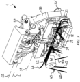
- Figure 1 shows a yarn knotter 1, which has a knotter frame 2, to which all functional components of the yarn knotter are attached, so that it forms an independent structural unit.
- An intermediate shaft 3 is mounted on the knotter frame 2 so that it can rotate about a longitudinal axis L.
- the intermediate shaft 3 has a shaft input 4 with which the intermediate shaft 3 can be driveably connected to an output element of a knotter drive shaft.
- the shaft input 4 is designed as a shaft journal, which can be connected to the knotter drive shaft using an output element of an angular gear, which will be explained later.
- a first drive bevel gear 5 and a second drive bevel gear 6 are secured in a rotationally fixed manner.
- the two drive bevel gears 5, 6 are arranged and designed in mirror image to a plane of symmetry which is arranged perpendicular to the longitudinal axis L. This means that the teeth of the two drive bevel gears 5, 6 point away from each other. In principle, they could also face each other.
- the gearing of the Drive bevel gears 5, 6 run uninterrupted around the circumference.
- the first drive bevel gear 5 is in tooth engagement with a first output bevel gear 7, which sits firmly on a first knotter hook shaft 9.
- the second drive bevel gear 6 is in meshing engagement with a second output bevel gear 8, which is non-rotatably seated on a second knotter hook shaft 10.
- the first knotter hook shaft 9 is rotatably mounted on the knotter frame 2 about a first knotter hook axis K1.
- the second knotter hook shaft 10 is rotatably mounted on the knotter frame 2 about a second knotter hook axis K2.
- the two knotter hook axes K1, K2 are aligned parallel to one another and intersect the longitudinal axis L at a right angle. Other arrangements are also conceivable in which the knotter hook axes K1, K2 cross the longitudinal axis at a distance and are possibly not arranged at right angles to the longitudinal axis L.
- the knotter hook axes K1, K2 do not necessarily have to be arranged parallel to one another.
- the first knotter hook shaft 9 has a first knotter hook 11 at its end to form a knot in a yarn strand.
- This includes a first hook part 13, which protrudes laterally from the first knotter hook shaft 9.
- a first knotting tongue 15, also protruding laterally is arranged in an adjustable manner in order to clamp a strand of yarn between the first hook part 13 and the first knotting tongue 15.
- the second knotter hook shaft 10 carries at its end, identical to the first knotter hook shaft 9, a second knotter hook 12, with a laterally projecting second hook part 14 and a second knotter tongue 16 movable thereto.
- the two knotter hooks 11, 12 can be designed identically or, preferably, mirror-symmetrically to that Plane of symmetry, which is arranged perpendicular to the longitudinal axis L.
- a first knotter hook control cam 17 is provided, which is arranged stationary to the knotter frame 2 and has an outer peripheral surface which runs around the first knotter hook axis K1.
- the first knotter tongue 15 is supported radially against the first knotter hook control cam 17 with a first knotter tongue roller 19 and is spring-loaded against it.
- the first knotter hook control cam 17 has a course around the first knotter hook axis K1, which deviates from a circular path, so that when the first knotter hook shaft 9 rotates, the lever effect is used in a known manner the first knotting tongue 15 is opened and closed relative to the first hook part 13.
- a second knotter hook control cam 18 is provided for controlling the second knotter tongue 16, against which the second knotter tongue 16 is supported with a second knotter tongue roller 20.
- the two knotter hook control cams 17, 18 are also designed to be mirror-symmetrical to the plane of symmetry, which is arranged perpendicular to the longitudinal axis L.
- the two knotter hook shafts 9, 10 are driven in opposite directions to one another. Since the two knotter hook control cams 17, 18 are also designed to be mirror-symmetrical, the two knotter hooks 11, 12 open at the same time.
- a reserve holder 21 is arranged between the two knotter hook shafts 9, 10, which is designed in the form of a lever arm and is mounted on the knotter frame 2 so that it can pivot about a first pivot axis S1.
- the first pivot axis S1 is arranged parallel to the longitudinal axis L.
- a lever 22 is provided, which is pivotally mounted on the knotter frame 2 about a second pivot axis S2, the second pivot axis S2 being arranged parallel to the longitudinal axis L.
- the lever 22 is supported against a control cam 24 via a control element in the form of a roller 23, the control cam 24 running around the longitudinal axis L and rotating with the intermediate shaft 3.
- the control cam 24 has a course that deviates from a circular path, so that according to Figure 1 the lever 22 can be raised and lowered.
- a coupling rod 25 is pivotally attached to the lever 22, which on the other hand is pivotally attached to the reserve holder 21, so that the movement of the lever 22 causes a movement of the reserve holder 21.
- the reserve holder 21 has a hook section 26 with which a strand of yarn is grasped and placed in the in Figure 1 illustrated orientation of the yarn knotter 1 can be pulled backwards to form a yarn reserve for forming yarn knots.
- the hook section 26 is slotted centrally in a plane that is arranged perpendicular to the first pivot axis S1.
- the hook section 26 brushes over a foldable knife 27.
- This Knife 27 is attached to the knotter frame 2 so that it can pivot about a third pivot axis S3, the third pivot axis S3 being arranged parallel to the longitudinal axis L.
- Two twine bars 30, 30' are also provided on the knotter frame 2, with the twine bar 30 for the first knotter hook 11 being explained as an example below.
- the yarn bar 30 'for the second knotter hook 12 is constructed accordingly.
- the yarn bar 30 is attached to the knotter frame 2 so that it can pivot about a locking axis R.
- the locking axis R is arranged at an angle to the first knotter hook axis K1, with the angle deviating from a right angle in the present case.
- the yarn bar 30 serves, as in the prior art yarn knotters, to press a strand of yarn onto the first knotter hook 11 in order to be able to form a knot.
- the yarn bar 30 is pivoted against the yarn strand in the course of knot formation.
- a further lever 31 is provided, which is mounted on the knotter frame 2 so that it can pivot about the second pivot axis S2.
- the lever 31 is supported via a control element in the form of a roller 32 against a control cam 33, the control cam 33 being arranged in a rotationally fixed manner on the intermediate shaft 3 and having a course that deviates from a circular path, so that the lever 31 rotates when the Intermediate shaft 3 is moved.
- a coupling rod 34 is pivotally attached to the lever 31, which on the other hand is pivotally attached to the yarn bar 30, so that the movement of the lever 31 is transmitted to the yarn bar 30.
- a deflection device 35 is provided. This includes a swivel arm 36, which is attached to the knotter frame 3 so that it can pivot about the second pivot axis S2.
- the pivot arm 36 is supported via a control element in the form of a roller 37 against a control cam 38 of the intermediate shaft 3.
- the control cam 38 also has a course that deviates from a circular path, so that the pivot arm 36 is pivoted about the second pivot axis S2 by rotating the intermediate shaft 3.
- a deflection roller 39 On a forward-facing section of the swivel arm 36, a deflection roller 39 is rotatably mounted, with the help of which a yarn strand can be deflected, as will be explained later, and due to the pivotable arrangement of the swivel arm 36, the deflection roller 39 can be pivoted into the area of a yarn strand or pivoted out of this area.
- the yarn knotter 1 has a bracket 40 at the bottom, which is part of the knotter frame 2.
- the bracket 40 also serves as a fastening element of the entire twine knotter 1 on a press and also has the function of a protective bracket for the knotter hooks 11, 12.
- the yarn knotter 1 is thus designed with its knotter frame 2 as an independent structural unit, with all functional components of the yarn knotter 1 being attached or stored on the knotter frame 2.
- the storage of the yarn bars 30, 30' on the knotter frame 2 represents a construction that makes the synchronization of the yarn bars 30, 30' to the knotter process particularly simple.
- the entire yarn knotter 1 can be attached to a press via the knotter frame 2, whereby the shaft input 4 of the intermediate shaft 3 can be connected to a knotter drive shaft of a press.
- twine knotter 1 there are no further functional components of the twine knotter on the knotter drive shaft of the press itself and also on the press or its frame, so that in the event of a defect, the entire twine knotter 1 can be dismantled as a structural unit without affecting other existing twine knotters on the same press or Twine knotters that are driven by the same knotter drive shaft can be influenced. No further dismantling of the other twine knotters is necessary.
- yarn knotter 1 corresponds to, arranged on a press, for example a baler from the agricultural sector, as is also the case in the WO 2011/054360 A1 is shown.
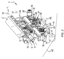
- the yarn knotter 1 is aligned in such a way that the longitudinal axis L is aligned in the direction of travel (F), with a deflection roller 41 deflecting the yarn coming from the bale to the yarn knotter.
- the knotter hooks 11, 12 are in one position Figure 2 starting position shown.
- the knotting tongues 15, 16 are in a closed position.
- the knotter hooks 11, 12 point outwards from each other in relation to the plane of symmetry already mentioned above, which is arranged perpendicular to the longitudinal axis L, that is, the first knotter hook 11 points in the direction of the deflection roller 41 and the second knotter hook 12 points in the direction of the deflection roller 39.
- the deflection roller 39 is pivoted into a forward position in the area of the yarn strand guide by means of the pivot arm 36.
- the reserve holder 21 is pivoted into a front position in which the hook section 26 of the reserve holder 21 is also in the guide area of the yarn strands.
- "pivoted forward” means that the components, ie the deflection roller 39 and the hook section 26 of the reserve holder 21, are to the right side in the illustration Figure 2 are pivoted.
- An upper strand of yarn 42 is shown as shown Figure 2 , from a spool of thread, not shown, via known tensioning and braking devices, also not shown, coming from the top left around the yarn deflection roller to the bottom right to the top of a bale.
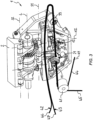
- a binding needle As shown later, is set in motion, which moves a lower strand of yarn 43 upwards.
- the lower yarn strand 43 runs from a lower one Roll of thread via known tensioning and braking devices, not shown, to the underside of the bale.
- the binding needle moves upward, it grabs the upper yarn strand 42 and transfers both yarn strands 42, 43 together into the knotter area.
- the tying needle moves in this area against the direction of travel and first passes the deflection roller 41, then the first knotter hook 11, then the hook section 26 of the reserve holder 21, then the second knotter hook 12 and finally the deflection roller 39.
- both yarn strands 42, 43 lie with their ends 44, 45 leading to the bale around the deflection roller 41 and rest on the knotting tongues 15, 16 of the knotter hooks 11, 12 and on the hook section 26 of the reserve holder 21.
- the yarn bars 30, 30 ' are still in their starting position outside the guide area of the yarn strands 42, 43.
- the deflection roller 39 was pivoted backwards away from the guide area of the yarn strands 42, 43 by means of the pivot arm 36, so that the yarn strands 42, 43 do not open the deflection roller 39 lie.
- the knotter hook shafts 9, 10 were rotated to a position in which the knotter hooks 11, 12 face each other and protrude into the guide area of the yarn strands 42, 43.
- the first knotter hook 11 was rotated clockwise when viewed from above and the second knotter hook 12 was rotated counterclockwise when viewed from above ( Figure 3 ).
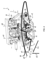
- Figure 4 shows the twine knotter 1 when the binding needle has almost reached its top position.
- the yarn bars 30, 30' are pivoted into the guide area of the yarn strands 42, 43 and press the yarn strands downward so that they are held on the knotter hooks 11, 12.
- the yarn strands 42, 43 are pressed down outside the pivoting range of the hook parts 13, 14 of the knotter hooks 11, 12 in order to ensure secure engagement of the yarn strands 42, 43 by the knotter hooks 11, 12 during further rotation of the same.
- the reserve holder 21 is pivoted backwards into a retracted position and has pulled a reserve of yarn between the two knotter hooks 11, 12.
- the yarn strands 42, 43 held on the reserve holder 21 were pulled over the knife 27, which evades the spring force, as described above.
- the deflection roller 39 is pivoted into a forward position into the free space spanned between the twine bar 30' on the second knotter hook 12 and the tip of the binding needle until the position according to FIG. 4 is reached.
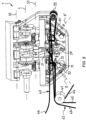
- the knotter hooks 11, 12 were further, in the same Direction of rotation as described above and are almost back in the starting position.
- the knotting hooks 11, 12 have the yarn strands 42, 43 wrapped around them and, with the now open knotting tongues 15, 16, grip over the ends running to the reserve holder 21.
- the reserve holder 21 moves continuously in accordance with the rotation of the knotter hooks 11, 12 back to the front position and thus successively releases the yarn reserve that the knotter hooks 11, 12 require in order to wind up the yarn strands 42, 43.
- the knotter hooks 11, 12 are rotated further, with the knotter tongues 15, 16 being transferred to their closed position.
- the yarn strands 42, 43 are now each clamped between the knotting tongues 15, 16 and the hook parts 13, 14.
- the reserve holder 21 is pivoted further forward to release more yarn reserve and has moved the yarn strands 42, 43 in front of the cutting edge 29 of the knife 27.
- the reserve holder 21 is also pivoted further forward.
- the yarn strands 42, 43 are severed using the knife 27 ( Figure 7 ).
- the knotter hooks 11, 12 are then rotated further until they have reached their starting position again ( Figure 8 ). In this position, the reserve holder 21 has also reached its front starting position again. When pivoted into the front position, the reserve holder 21 takes over the ends 46, 47 of the two thread strands 42, 43 leading to the thread spools, which are in the in Figure 8 right knotter area over the Deflection roller 39 runs to the second knotter hook 12.
- the yarn strands 42, 43 are raised over front slopes 48 on the hook section 26 of the reserve holder 21 as it moves forward until they jump into the hook section 26.
- FIG 9 shows the starting position of the binding device.
- the upper thread strand 42 runs from the upper thread spool (not shown) over the deflection roller 41 to the top of a bale 49.
- the bale 49 is pressed and ejected in the direction of arrow P, which indicates the pressing direction.
- the arrow F indicates the direction of travel of the baler, to which the terms "front” and "rear” refer.
- the upper strand of yarn 42 is knotted to a lower strand of yarn 43 near a rear edge of the bale 49.
- the lower yarn strand 43 runs along the rear side of the bale 49 downwards and along the underside of the bale to the front, where it runs between two rollers 50, 51 of the binding needle 52. From there it continues through an optional switchable yarn clamp 53 via thread guides to a lower thread spool (not shown).
- the binding needle 52 pivoted through the press channel through which the bale 49 is pressed, and is not explicitly shown here, and thereby transferred the lower yarn strand 43 upwards.
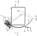
- the binding needle 52 has grasped the upper yarn strand 42 with its front roller 50 and moves both yarn strands 42, 43 into the knotter area.
- the knotter elements, ie twine bars 30, 30' and reserve holder 21, are still in their starting position. Only the knotter hooks 11, 12 are twisted into a yarn take-up position.
- Figure 12 shows the overall representation of the binding device, which corresponds to the position in Figure 4 corresponds.
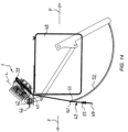
- Figure 13 corresponds in its position to the Figure 5 . It can be seen that the binding needle 52 has left the knotter area again, releasing the upper yarn strand 42 and placing the lower yarn strand 43 on the deflection roller 39.
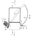
- Figure 15 shows the entire binding device after the binding process has been completed.
- the binding needle 52 is back in its starting position, as are the knotter hooks 11, 12 of the twine knotter 1. However, the knots are still arranged on the knotter hooks 11, 12. The position corresponds to the illustration Figure 8 .
- the yarn strands 42, 43 are pressed between the rear finished bale 49 and the new bale 49 '.
- the yarn strands 42, 43 pull the knot from the first knotter hook 11.
- the lower yarn strand 43 becomes the lower yarn strand 43 when the bales 49, 49' are pushed further subjected to tension, which pulls the knot from the second knotter hook 12 via the deflection roller 41 and the deflection roller 39.
- the lower yarn strand 43 can be pulled with a switchable yarn clamp 53 directly after the end of the Movement of the binding needle 52 can be blocked.
- the entire yarn pull which is required when moving the bales 49, 49 'in the press channel, takes effect on the upper yarn strand 42 and pulls off the second knot.
- the yarn clamp 53 is then released again and both yarn strands 42, 43 can be pulled off during further pressing.
- the second knot is only pulled off by the lower yarn strand 43 from the second knotter hook 12, since in the binding process described the knot removal only takes place due to the bale movement in the press channel and the upper yarn strand 42 does not receive any tensile force from this side after the binding process. Therefore, it appears necessary to provide at least a sufficient tensile force from the lower yarn strand 43, which is provided regardless of the pressing density.
- the switchable yarn clamp 53 described above represents a relatively simple measure. Alternatively, active devices that directly exert tension on the upper yarn strand 42 are also conceivable.
- Figure 17 shows a side view of a yarn knotter arrangement according to the invention with a yarn knotter 1 according to the Figures 1 to 16 .
- another twine knotter can also be used.
- the illustration is only an example in this regard.
- the yarn knotter 1 is attached with its knotter frame to a frame 55 of the yarn knotter arrangement.
- several yarn knotters 1 are arranged next to one another and connected to the same frame 55.
- the deflection roller 41 of the twine knotter 1 serves to deflect the yarn coming from the bale towards the twine knotter 1, as shown in, for example Figure 3 is shown.
- the deflection roller 41 is connected to a length-variable adjusting device 54 via a roller holder 58.
- the adjusting device 54 is mounted on the frame 55 so that it can pivot about a pivot axis S.
- the adjusting device 54 is designed in the form of a telescopic rod and has a cylinder tube 56 and a cylinder rod 57 guided therein along a telescopic axis T. At one end facing away from the cylinder tube 56, the cylinder rod 57 carries a roll holder 58.
- the roll holder 58 is U-shaped and accommodates the deflection roller 41 between two fork arms 59, 60.
- Outwardly projecting guide pins 61 are provided on the roller holder 58, only one of which is visible in the figures.
- the guide pins 61 protrude in opposite directions from the roll holder 58 and are each connected to one of the fork arms 59, 60.
- the guide pins 61 are each guided in a translationally movable manner in a guide groove 62, 63 of the frame 55.
- the guide grooves 62, 63 are each arranged in a guide wall 64, 65 of the frame 55.
- the frame 55 is made of sheet metal material, with the guide walls 64, 65 being formed from the sheet material.
- the guide grooves 62, 63 are aligned somewhat parallel to the pressing direction, with the telescoping axis T forming an angle to the guide grooves 62, 63.
- the adjusting device 54 can be designed in the form of a compression spring element or a gas pressure spring, with the cylinder rod 57 being subjected to force in the direction of an extended position relative to the cylinder tube 56.
- a tensile force within the yarn a radial force is created by the yarn on the deflection roller 41, so that the adjusting device 54 is moved together counter to the force that acts on the cylinder positions 57 in the direction of the extended position.
- spring means in the adjusting device 54 can be biased in such a way that The adjusting device 54 does not move together before a predetermined limit force is reached.
- Figure 19 shows schematically the force relationships on the deflection roller 41 when a yarn is wrapped according to Figure 3 .
- the lower yarn strand 43 i.e. the end 45 of the lower yarn strand 43 leading to the bale and the end 47 of the lower yarn strand 43 leading to the spool of yarn, is shown.
- the lower yarn strand 43 is wound around the deflection roller 41 over a wrap angle ⁇ .
- the tensile forces F K present in the lower yarn strand 43 result in a radial force F R being exerted on the deflection roller 41 by the lower yarn strand 43.
- This radial force F R is the force with which the adjusting device 54 ( Figure 17 ) is acted upon in the opposite direction to the extended position, with the deflection roller 41 at least when a limit tensile force is exceeded in an adjustment direction V, which is through the guide grooves 62, 63 ( Figure 18 ) is specified, is moved. This displacement reduces the tensile force Fz in the lower yarn strand 43, so that a yield point of the yarn material is not exceeded and thus the yarn strand breaks.
Landscapes
- Life Sciences & Earth Sciences (AREA)
- Environmental Sciences (AREA)
- Engineering & Computer Science (AREA)
- Mechanical Engineering (AREA)
- Basic Packing Technique (AREA)
- Braiding, Manufacturing Of Bobbin-Net Or Lace, And Manufacturing Of Nets By Knotting (AREA)
- Preliminary Treatment Of Fibers (AREA)
Claims (13)
- Dispositif de nouage de fil pour nouer du fil afin ficeler une balle, le dispositif de nouage de fil présentant les éléments suivants :un noueur de fil (1) etune aiguille de liaison (52, 52') pour acheminer les écheveaux de fil dans une zone de nouage du noueur de fil (1),caractérisé en ce quele dispositif de nouage de fil présente en outre un rouleau d'inversion (41) réglable par rapport au noueur de fil (1) grâce auquel le fil venant de la balle (42, 43) est dévié en direction du noueur de fil (1), et un dispositif de réglage (54) pour régler la position du rouleau d'inversion (41) en fonction de la force (FR) exercée par le fil (42, 43) sur le rouleau d'inversion (41) .
- Dispositif de nouage de fil selon la revendication 1, caractérisé en ce que
le dispositif de réglage (54) est réglable au moyen d'un élément à ressort, hydraulique ou pneumatique. - Dispositif de nouage de fil selon une des revendications 1 ou 2, caractérisé en ce quele dispositif de nouage de fil (55) présente un cadre sur lequel le rouleau d'inversion (41) est guidé en étant mobile en translation,le dispositif de réglage (54) s'appuie d'une part sur le cadre (55) et d'autre part s'appuie contre le cylindre d'inversion (41), etle dispositif de réglage (54) est réglable en longueur.
- Dispositif de nouage de fil selon la revendication 3, caractérisé en ce que
le rouleau d'inversion (41) est fixé à un support de rouleau (58) qui est connecté au dispositif de réglage (54) . - Dispositif de nouage de fil selon la revendication 4, caractérisé en ce que
le support de rouleau (58) présente des tourillons de guidage saillant latéralement (61) qui sont guidés dans des rainures de guidage (62, 63) du cadre (55). - Dispositif de nouage de fil selon une des revendications 1 à 5, caractérisé en ce que
le dispositif de réglage (54) présente une barre télescopique (56, 57) qui est sollicitée avec de la force pour prendre une position sortie. - Dispositif de nouage de fil selon la revendication 6, caractérisé en ce que
la barre télescopique (56, 57) est sollicitée par ressort pour prendre la position sortie. - Dispositif de nouage de fil selon une des revendications 1 à 7, caractérisé en ce que
le noueur de fil (1) présente des éléments suivants :un cadre de noueur (2),un arbre intermédiaire (3) qui s'appuie en rotation au niveau du cadre de noueur (2) autour d'un axe longitudinal (1) et qui présente une entrée d'arbre (4) pour connecter l'arbre intermédiaire (3) à un élément mené (61) d'un arbre moteur de noueur (54), etau moins un arbre à crochet de noueur (9, 10) s'appuyant de manière à pouvoir tourner autour d'un axe de crochet de noueur (K1, K2) au niveau du cadre de noueur (2) et qui est connecté avec entraînement avec l'arbre intermédiaire (3) et comporte un crochet de noueur (11, 12) pour former un noeud. - Dispositif de nouage de fil selon la revendication 8, caractérisé en ce que
le noueur de fil (1) est réalisé sous forme d'une unité de construction autonome, le noueur de fil (1) étant connectable avec entraînement de manière dissociable avec l'arbre moteur de noueur (54) par l'entrée d'arbre (4) de l'arbre intermédiaire (3). - D Dispositif de nouage de fil selon une des revendications 1 à 9, caractérisé en ce
qu'il est prévu deux arbres à crochet de noueur (9, 10) qui s'appuient respectivement de manière à pouvoir tourner au niveau du cadre de noueur (2) autour d'un axe de crochet de noueur (K1, K2) et qui sont respectivement connectés avec entraînement à l'arbre intermédiaire (3). - Dispositif de nouage de fil selon une des revendications 1 à 10, caractérisé en ce
qu'il est prévu un dispositif d'inversion (39) pour dévier les écheveaux de fil (42, 43) qui sont maintenus par le cadre de noueur (2) et entraînés par l'arbre intermédiaire (3). - Dispositif de nouage de fil selon une des revendications 1 à 11, caractérisé en ce quele dispositif de presse à balles présente un canal de presse lequel, au moyen d'un piston de presse, du matériau de balle est comprimé pour former une balle dans un sens de presse (P),le noueur de fil (1) est disposé à côté du canal de presse etle rouleau d'inversion (41) est disposé entre le canal de presse et le noueur de fil (1),le rouleau d'inversion (41) est réglable du moins sensiblement parallèlement au sens de presse (P).
- Dispositif de nouage de fil selon la revendication 12, caractérisé en ce que
le rouleau d'inversion (41) est disposé de manière à ce que le fil soit guidé du moins sensiblement dans le sens de presse (P) vers le noueur de fil (1).
Applications Claiming Priority (2)
| Application Number | Priority Date | Filing Date | Title |
|---|---|---|---|
| DE202018101650.4U DE202018101650U1 (de) | 2018-03-23 | 2018-03-23 | Garnknoteranordnung zum Knoten von Garn und Ballenpressvorrichtung |
| PCT/EP2019/057150 WO2019180172A1 (fr) | 2018-03-23 | 2019-03-21 | Ensemble de nouage de fils et dispositif de compression de balles |
Publications (3)
| Publication Number | Publication Date |
|---|---|
| EP3768067A1 EP3768067A1 (fr) | 2021-01-27 |
| EP3768067C0 EP3768067C0 (fr) | 2024-01-03 |
| EP3768067B1 true EP3768067B1 (fr) | 2024-01-03 |
Family
ID=65911166
Family Applications (1)
| Application Number | Title | Priority Date | Filing Date |
|---|---|---|---|
| EP19713429.9A Active EP3768067B1 (fr) | 2018-03-23 | 2019-03-21 | Ensemble de nouage de fils et dispositif de compression de balles |
Country Status (8)
| Country | Link |
|---|---|
| US (1) | US11528849B2 (fr) |
| EP (1) | EP3768067B1 (fr) |
| CN (1) | CN111902041B (fr) |
| DE (1) | DE202018101650U1 (fr) |
| ES (1) | ES2972143T3 (fr) |
| PL (1) | PL3768067T3 (fr) |
| RU (1) | RU2758012C1 (fr) |
| WO (1) | WO2019180172A1 (fr) |
Families Citing this family (6)
| Publication number | Priority date | Publication date | Assignee | Title |
|---|---|---|---|---|
| EP4039081B1 (fr) * | 2021-02-04 | 2025-05-14 | Schumacher Bergische Werke GmbH | Noueur de fil et procédé de formation de deux n uds dans un fil |
| CN113853956B (zh) * | 2021-11-01 | 2022-08-16 | 泰州市力鼎机械设备有限公司 | 基于d型打结器原理的双齿盘驱动打结器 |
| CN114846988B (zh) * | 2022-04-14 | 2023-07-07 | 黑龙江银锚建筑机械有限公司 | 一种农作物采收用打结捆扎装置 |
| US12302797B1 (en) * | 2023-11-07 | 2025-05-20 | Great Plains Manufacturing, Inc. | Locking mechanism for knotter assemblies |
| CN117958042B (zh) * | 2024-02-29 | 2025-12-09 | 东北农业大学 | 秸秆包缠绳捆扎装置 |
| CN118318614B (zh) * | 2024-06-13 | 2026-01-16 | 北京市农业机械研究所有限公司 | 捆扎装置、方法及韭菜收割打捆一体机 |
Family Cites Families (16)
| Publication number | Priority date | Publication date | Assignee | Title |
|---|---|---|---|---|
| DE2111894C3 (de) * | 1971-03-12 | 1980-07-10 | Persoener Ab, Ystad (Schweden) | Vorrichtung zum Umbinden von Ballen mit einem PreBkanal und einem im Preßkanal hin- und herverschiebbaren Preßkolben |
| DE2628540C3 (de) * | 1976-06-25 | 1980-05-14 | Lindemann Maschinenfabrik Gmbh, 4000 Duesseldorf | Vorrichtung zum Umschnüren von Ballen |
| US4074623A (en) | 1976-11-16 | 1978-02-21 | Hesston Corporation | Method for binding a crop bale |
| DE3202233C2 (de) * | 1982-01-25 | 1987-05-14 | Lindemann Maschinenfabrik GmbH, 4000 Düsseldorf | Vorrichtung zum Umschnüren von Ballen |
| US5855166A (en) * | 1996-10-09 | 1999-01-05 | Mcpherson; Bobby Roy | Retrofit measuring device for a hay baler |
| US5783816A (en) * | 1996-10-09 | 1998-07-21 | Mcpherson; Bobby Roy | Measuring device for a hay baler |
| DE19808416C2 (de) * | 1998-02-28 | 1999-12-23 | Hermann Schwelling | Antriebs- und Lagerungsvorrichtung für die Verdrillscheiben der Umschnüreinrichtung für Abfälle von Ballenpressen |
| DE10011909A1 (de) * | 2000-03-11 | 2001-09-27 | Ralf Peter Haas | Bandahle |
| ITBO20020755A1 (it) * | 2002-12-02 | 2004-06-03 | Pieri Srl | Apparato per il fissaggio senza saldatura della coda |
| CN101810082B (zh) * | 2009-02-19 | 2011-08-17 | 中国农业机械化科学研究院 | 固定式大捆秸秆打捆机 |
| CN102665387B (zh) | 2009-11-03 | 2016-02-24 | 腊斯佩系统技术有限两合公司 | 双结式捆绳打结器单元 |
| TR201808072T4 (tr) * | 2012-06-14 | 2018-07-23 | Rasspe Systemtechnik GmbH | Sicim düğümleme mekanizması. |
| CN203691996U (zh) * | 2013-08-16 | 2014-07-09 | 北京航星机器制造有限公司 | 弹性夹绳d型打结器 |
| EP2941951B1 (fr) * | 2014-05-05 | 2018-04-25 | Bollegraaf Patents and Brands B.V. | Presse à balles avec un système de ficellage et procédé d'alimentation de corde d'un dispositif de nouage d'une presse à balles |
| US9510511B2 (en) * | 2015-04-16 | 2016-12-06 | Deere & Company | Rotary brush for cleaning round module builder belts |
| US20160355292A1 (en) * | 2015-06-03 | 2016-12-08 | Deere & Company | Module wrap feed system |
-
2018
- 2018-03-23 DE DE202018101650.4U patent/DE202018101650U1/de active Active
-
2019
- 2019-03-21 US US16/975,965 patent/US11528849B2/en active Active
- 2019-03-21 ES ES19713429T patent/ES2972143T3/es active Active
- 2019-03-21 CN CN201980021182.1A patent/CN111902041B/zh active Active
- 2019-03-21 PL PL19713429.9T patent/PL3768067T3/pl unknown
- 2019-03-21 WO PCT/EP2019/057150 patent/WO2019180172A1/fr not_active Ceased
- 2019-03-21 EP EP19713429.9A patent/EP3768067B1/fr active Active
- 2019-03-21 RU RU2020130264A patent/RU2758012C1/ru active
Also Published As
| Publication number | Publication date |
|---|---|
| CN111902041B (zh) | 2022-09-27 |
| EP3768067C0 (fr) | 2024-01-03 |
| RU2758012C1 (ru) | 2021-10-25 |
| ES2972143T3 (es) | 2024-06-11 |
| CN111902041A (zh) | 2020-11-06 |
| PL3768067T3 (pl) | 2024-07-08 |
| EP3768067A1 (fr) | 2021-01-27 |
| DE202018101650U1 (de) | 2019-06-27 |
| US11528849B2 (en) | 2022-12-20 |
| US20210000018A1 (en) | 2021-01-07 |
| WO2019180172A1 (fr) | 2019-09-26 |
Similar Documents
| Publication | Publication Date | Title |
|---|---|---|
| EP3768067B1 (fr) | Ensemble de nouage de fils et dispositif de compression de balles | |
| EP2861055B1 (fr) | Dispositif de nouage de fils | |
| EP0157898B1 (fr) | Mécanisme de liage pour presses à balles rondes | |
| EP1170984A1 (fr) | Procede pour envelopper une balle ronde pressee dans une presse a balles rondes, dispositif d'enveloppement avec film et presse a balles rondes pourvue d'un tel dispositif | |
| DE2530320C3 (de) | Bindevorrichtung für Wickelballenpressen | |
| EP1190618A1 (fr) | Presse à balles pour matériau non-aggloméré | |
| EP4039081B1 (fr) | Noueur de fil et procédé de formation de deux n uds dans un fil | |
| EP3788865B1 (fr) | Noueurs de fil | |
| EP4261028B1 (fr) | Presse à balles à canal avec arrêt croisé | |
| DE20110161U1 (de) | Knoterhaken und damit ausgerüsteter Garnknoter | |
| EP1982576B1 (fr) | Presse à balles dotée d'un dispositif de nouage | |
| DE20110162U1 (de) | Garnknoter | |
| EP2660160A2 (fr) | Presse à paquet à canal | |
| EP1234495B1 (fr) | Presse-botteleuse avec dispositif de liage | |
| DE102024107851B3 (de) | Garnknoter zum Erzeugen eines Knotens in Garnsträngen | |
| EP3391729B1 (fr) | Presse à balles | |
| DE29905765U1 (de) | Rundballenpresse | |
| DE3408149A1 (de) | Bindegarn-spannvorrichtung | |
| EP4311427B1 (fr) | Dispositif de liage pour presse à balles | |
| DE19720542A1 (de) | Vorrichtung und Verfahren zur Sicherung von Garnenden | |
| DE102008000988A1 (de) | Vorrichtung und Verfahren zur Erzeugung von Großballen in einer Großballenpresse | |
| DE202024101387U1 (de) | Garnknoter zum Erzeugen eines Knotens in Garnsträngen | |
| DE102024131696A1 (de) | Knotereinrichtung | |
| DE2916014A1 (de) | Verfahren zum knoten und schneiden eines garnstranges beim umschnueren von ballen in landwirtschaftlichen ballenpressen sowie knuepfapparat zur durchfuehrung des verfahrens |
Legal Events
| Date | Code | Title | Description |
|---|---|---|---|
| STAA | Information on the status of an ep patent application or granted ep patent |
Free format text: STATUS: UNKNOWN |
|
| STAA | Information on the status of an ep patent application or granted ep patent |
Free format text: STATUS: THE INTERNATIONAL PUBLICATION HAS BEEN MADE |
|
| PUAI | Public reference made under article 153(3) epc to a published international application that has entered the european phase |
Free format text: ORIGINAL CODE: 0009012 |
|
| STAA | Information on the status of an ep patent application or granted ep patent |
Free format text: STATUS: REQUEST FOR EXAMINATION WAS MADE |
|
| 17P | Request for examination filed |
Effective date: 20200814 |
|
| AK | Designated contracting states |
Kind code of ref document: A1 Designated state(s): AL AT BE BG CH CY CZ DE DK EE ES FI FR GB GR HR HU IE IS IT LI LT LU LV MC MK MT NL NO PL PT RO RS SE SI SK SM TR |
|
| AX | Request for extension of the european patent |
Extension state: BA ME |
|
| DAV | Request for validation of the european patent (deleted) | ||
| DAX | Request for extension of the european patent (deleted) | ||
| GRAP | Despatch of communication of intention to grant a patent |
Free format text: ORIGINAL CODE: EPIDOSNIGR1 |
|
| STAA | Information on the status of an ep patent application or granted ep patent |
Free format text: STATUS: GRANT OF PATENT IS INTENDED |
|
| INTG | Intention to grant announced |
Effective date: 20230728 |
|
| GRAS | Grant fee paid |
Free format text: ORIGINAL CODE: EPIDOSNIGR3 |
|
| GRAA | (expected) grant |
Free format text: ORIGINAL CODE: 0009210 |
|
| STAA | Information on the status of an ep patent application or granted ep patent |
Free format text: STATUS: THE PATENT HAS BEEN GRANTED |
|
| AK | Designated contracting states |
Kind code of ref document: B1 Designated state(s): AL AT BE BG CH CY CZ DE DK EE ES FI FR GB GR HR HU IE IS IT LI LT LU LV MC MK MT NL NO PL PT RO RS SE SI SK SM TR |
|
| REG | Reference to a national code |
Ref country code: GB Ref legal event code: FG4D Free format text: NOT ENGLISH |
|
| REG | Reference to a national code |
Ref country code: CH Ref legal event code: EP |
|
| REG | Reference to a national code |
Ref country code: DE Ref legal event code: R096 Ref document number: 502019010286 Country of ref document: DE |
|
| REG | Reference to a national code |
Ref country code: IE Ref legal event code: FG4D Free format text: LANGUAGE OF EP DOCUMENT: GERMAN |
|
| U01 | Request for unitary effect filed |
Effective date: 20240111 |
|
| RAP4 | Party data changed (patent owner data changed or rights of a patent transferred) |
Owner name: SCHUMACHER BERGISCHE WERKE GMBH |
|
| U07 | Unitary effect registered |
Designated state(s): AT BE BG DE DK EE FI FR IT LT LU LV MT NL PT SE SI Effective date: 20240119 |
|
| U20 | Renewal fee for the european patent with unitary effect paid |
Year of fee payment: 6 Effective date: 20240320 |
|
| REG | Reference to a national code |
Ref country code: ES Ref legal event code: FG2A Ref document number: 2972143 Country of ref document: ES Kind code of ref document: T3 Effective date: 20240611 |
|
| PG25 | Lapsed in a contracting state [announced via postgrant information from national office to epo] |
Ref country code: IS Free format text: LAPSE BECAUSE OF FAILURE TO SUBMIT A TRANSLATION OF THE DESCRIPTION OR TO PAY THE FEE WITHIN THE PRESCRIBED TIME-LIMIT Effective date: 20240503 |
|
| PG25 | Lapsed in a contracting state [announced via postgrant information from national office to epo] |
Ref country code: GR Free format text: LAPSE BECAUSE OF FAILURE TO SUBMIT A TRANSLATION OF THE DESCRIPTION OR TO PAY THE FEE WITHIN THE PRESCRIBED TIME-LIMIT Effective date: 20240404 |
|
| PG25 | Lapsed in a contracting state [announced via postgrant information from national office to epo] |
Ref country code: RS Free format text: LAPSE BECAUSE OF FAILURE TO SUBMIT A TRANSLATION OF THE DESCRIPTION OR TO PAY THE FEE WITHIN THE PRESCRIBED TIME-LIMIT Effective date: 20240403 Ref country code: HR Free format text: LAPSE BECAUSE OF FAILURE TO SUBMIT A TRANSLATION OF THE DESCRIPTION OR TO PAY THE FEE WITHIN THE PRESCRIBED TIME-LIMIT Effective date: 20240103 |
|
| PG25 | Lapsed in a contracting state [announced via postgrant information from national office to epo] |
Ref country code: CZ Free format text: LAPSE BECAUSE OF FAILURE TO SUBMIT A TRANSLATION OF THE DESCRIPTION OR TO PAY THE FEE WITHIN THE PRESCRIBED TIME-LIMIT Effective date: 20240103 |
|
| PG25 | Lapsed in a contracting state [announced via postgrant information from national office to epo] |
Ref country code: RS Free format text: LAPSE BECAUSE OF FAILURE TO SUBMIT A TRANSLATION OF THE DESCRIPTION OR TO PAY THE FEE WITHIN THE PRESCRIBED TIME-LIMIT Effective date: 20240403 Ref country code: NO Free format text: LAPSE BECAUSE OF FAILURE TO SUBMIT A TRANSLATION OF THE DESCRIPTION OR TO PAY THE FEE WITHIN THE PRESCRIBED TIME-LIMIT Effective date: 20240403 Ref country code: IS Free format text: LAPSE BECAUSE OF FAILURE TO SUBMIT A TRANSLATION OF THE DESCRIPTION OR TO PAY THE FEE WITHIN THE PRESCRIBED TIME-LIMIT Effective date: 20240503 Ref country code: HR Free format text: LAPSE BECAUSE OF FAILURE TO SUBMIT A TRANSLATION OF THE DESCRIPTION OR TO PAY THE FEE WITHIN THE PRESCRIBED TIME-LIMIT Effective date: 20240103 Ref country code: GR Free format text: LAPSE BECAUSE OF FAILURE TO SUBMIT A TRANSLATION OF THE DESCRIPTION OR TO PAY THE FEE WITHIN THE PRESCRIBED TIME-LIMIT Effective date: 20240404 Ref country code: CZ Free format text: LAPSE BECAUSE OF FAILURE TO SUBMIT A TRANSLATION OF THE DESCRIPTION OR TO PAY THE FEE WITHIN THE PRESCRIBED TIME-LIMIT Effective date: 20240103 |
|
| REG | Reference to a national code |
Ref country code: DE Ref legal event code: R097 Ref document number: 502019010286 Country of ref document: DE |
|
| PG25 | Lapsed in a contracting state [announced via postgrant information from national office to epo] |
Ref country code: SM Free format text: LAPSE BECAUSE OF FAILURE TO SUBMIT A TRANSLATION OF THE DESCRIPTION OR TO PAY THE FEE WITHIN THE PRESCRIBED TIME-LIMIT Effective date: 20240103 |
|
| PG25 | Lapsed in a contracting state [announced via postgrant information from national office to epo] |
Ref country code: SK Free format text: LAPSE BECAUSE OF FAILURE TO SUBMIT A TRANSLATION OF THE DESCRIPTION OR TO PAY THE FEE WITHIN THE PRESCRIBED TIME-LIMIT Effective date: 20240103 |
|
| PG25 | Lapsed in a contracting state [announced via postgrant information from national office to epo] |
Ref country code: SM Free format text: LAPSE BECAUSE OF FAILURE TO SUBMIT A TRANSLATION OF THE DESCRIPTION OR TO PAY THE FEE WITHIN THE PRESCRIBED TIME-LIMIT Effective date: 20240103 Ref country code: SK Free format text: LAPSE BECAUSE OF FAILURE TO SUBMIT A TRANSLATION OF THE DESCRIPTION OR TO PAY THE FEE WITHIN THE PRESCRIBED TIME-LIMIT Effective date: 20240103 Ref country code: RO Free format text: LAPSE BECAUSE OF FAILURE TO SUBMIT A TRANSLATION OF THE DESCRIPTION OR TO PAY THE FEE WITHIN THE PRESCRIBED TIME-LIMIT Effective date: 20240103 |
|
| REG | Reference to a national code |
Ref country code: CH Ref legal event code: PL |
|
| PLBE | No opposition filed within time limit |
Free format text: ORIGINAL CODE: 0009261 |
|
| STAA | Information on the status of an ep patent application or granted ep patent |
Free format text: STATUS: NO OPPOSITION FILED WITHIN TIME LIMIT |
|
| PG25 | Lapsed in a contracting state [announced via postgrant information from national office to epo] |
Ref country code: MC Free format text: LAPSE BECAUSE OF FAILURE TO SUBMIT A TRANSLATION OF THE DESCRIPTION OR TO PAY THE FEE WITHIN THE PRESCRIBED TIME-LIMIT Effective date: 20240103 |
|
| PG25 | Lapsed in a contracting state [announced via postgrant information from national office to epo] |
Ref country code: MC Free format text: LAPSE BECAUSE OF FAILURE TO SUBMIT A TRANSLATION OF THE DESCRIPTION OR TO PAY THE FEE WITHIN THE PRESCRIBED TIME-LIMIT Effective date: 20240103 |
|
| 26N | No opposition filed |
Effective date: 20241007 |
|
| GBPC | Gb: european patent ceased through non-payment of renewal fee |
Effective date: 20240403 |
|
| PG25 | Lapsed in a contracting state [announced via postgrant information from national office to epo] |
Ref country code: GB Free format text: LAPSE BECAUSE OF NON-PAYMENT OF DUE FEES Effective date: 20240403 |
|
| PG25 | Lapsed in a contracting state [announced via postgrant information from national office to epo] |
Ref country code: IE Free format text: LAPSE BECAUSE OF NON-PAYMENT OF DUE FEES Effective date: 20240321 |
|
| PG25 | Lapsed in a contracting state [announced via postgrant information from national office to epo] |
Ref country code: IE Free format text: LAPSE BECAUSE OF NON-PAYMENT OF DUE FEES Effective date: 20240321 Ref country code: GB Free format text: LAPSE BECAUSE OF NON-PAYMENT OF DUE FEES Effective date: 20240403 Ref country code: CH Free format text: LAPSE BECAUSE OF NON-PAYMENT OF DUE FEES Effective date: 20240331 |
|
| PGFP | Annual fee paid to national office [announced via postgrant information from national office to epo] |
Ref country code: PL Payment date: 20250307 Year of fee payment: 7 |
|
| U20 | Renewal fee for the european patent with unitary effect paid |
Year of fee payment: 7 Effective date: 20250325 |
|
| PGFP | Annual fee paid to national office [announced via postgrant information from national office to epo] |
Ref country code: ES Payment date: 20250416 Year of fee payment: 7 |
|
| PG25 | Lapsed in a contracting state [announced via postgrant information from national office to epo] |
Ref country code: CY Free format text: LAPSE BECAUSE OF FAILURE TO SUBMIT A TRANSLATION OF THE DESCRIPTION OR TO PAY THE FEE WITHIN THE PRESCRIBED TIME-LIMIT; INVALID AB INITIO Effective date: 20190321 |
|
| PG25 | Lapsed in a contracting state [announced via postgrant information from national office to epo] |
Ref country code: HU Free format text: LAPSE BECAUSE OF FAILURE TO SUBMIT A TRANSLATION OF THE DESCRIPTION OR TO PAY THE FEE WITHIN THE PRESCRIBED TIME-LIMIT; INVALID AB INITIO Effective date: 20190321 |
|
| PGFP | Annual fee paid to national office [announced via postgrant information from national office to epo] |
Ref country code: TR Payment date: 20260316 Year of fee payment: 8 |