EP3768196B1 - Prothesensystem - Google Patents
Prothesensystem Download PDFInfo
- Publication number
- EP3768196B1 EP3768196B1 EP19722780.4A EP19722780A EP3768196B1 EP 3768196 B1 EP3768196 B1 EP 3768196B1 EP 19722780 A EP19722780 A EP 19722780A EP 3768196 B1 EP3768196 B1 EP 3768196B1
- Authority
- EP
- European Patent Office
- Prior art keywords
- coil
- electromagnetic transducer
- prosthetic system
- primary
- prosthesis
- Prior art date
- Legal status (The legal status is an assumption and is not a legal conclusion. Google has not performed a legal analysis and makes no representation as to the accuracy of the status listed.)
- Not-in-force
Links
Images

Classifications
-
- A—HUMAN NECESSITIES
- A61—MEDICAL OR VETERINARY SCIENCE; HYGIENE
- A61N—ELECTROTHERAPY; MAGNETOTHERAPY; RADIATION THERAPY; ULTRASOUND THERAPY
- A61N1/00—Electrotherapy; Circuits therefor
- A61N1/02—Details
- A61N1/04—Electrodes
- A61N1/05—Electrodes for implantation or insertion into the body, e.g. heart electrode
- A61N1/0551—Spinal or peripheral nerve electrodes
-
- A—HUMAN NECESSITIES
- A61—MEDICAL OR VETERINARY SCIENCE; HYGIENE
- A61F—FILTERS IMPLANTABLE INTO BLOOD VESSELS; PROSTHESES; DEVICES PROVIDING PATENCY TO, OR PREVENTING COLLAPSING OF, TUBULAR STRUCTURES OF THE BODY, e.g. STENTS; ORTHOPAEDIC, NURSING OR CONTRACEPTIVE DEVICES; FOMENTATION; TREATMENT OR PROTECTION OF EYES OR EARS; BANDAGES, DRESSINGS OR ABSORBENT PADS; FIRST-AID KITS
- A61F2/00—Filters implantable into blood vessels; Prostheses, i.e. artificial substitutes or replacements for parts of the body; Appliances for connecting them with the body; Devices providing patency to, or preventing collapsing of, tubular structures of the body, e.g. stents
- A61F2/02—Prostheses implantable into the body
- A61F2/30—Joints
- A61F2/32—Joints for the hip
- A61F2/36—Femoral heads ; Femoral endoprostheses
-
- A—HUMAN NECESSITIES
- A61—MEDICAL OR VETERINARY SCIENCE; HYGIENE
- A61F—FILTERS IMPLANTABLE INTO BLOOD VESSELS; PROSTHESES; DEVICES PROVIDING PATENCY TO, OR PREVENTING COLLAPSING OF, TUBULAR STRUCTURES OF THE BODY, e.g. STENTS; ORTHOPAEDIC, NURSING OR CONTRACEPTIVE DEVICES; FOMENTATION; TREATMENT OR PROTECTION OF EYES OR EARS; BANDAGES, DRESSINGS OR ABSORBENT PADS; FIRST-AID KITS
- A61F2/00—Filters implantable into blood vessels; Prostheses, i.e. artificial substitutes or replacements for parts of the body; Appliances for connecting them with the body; Devices providing patency to, or preventing collapsing of, tubular structures of the body, e.g. stents
- A61F2/02—Prostheses implantable into the body
- A61F2/48—Operating or control means, e.g. from outside the body, control of sphincters
- A61F2/482—Electrical means
-
- A—HUMAN NECESSITIES
- A61—MEDICAL OR VETERINARY SCIENCE; HYGIENE
- A61N—ELECTROTHERAPY; MAGNETOTHERAPY; RADIATION THERAPY; ULTRASOUND THERAPY
- A61N1/00—Electrotherapy; Circuits therefor
- A61N1/18—Applying electric currents by contact electrodes
- A61N1/32—Applying electric currents by contact electrodes alternating or intermittent currents
- A61N1/36—Applying electric currents by contact electrodes alternating or intermittent currents for stimulation
-
- A—HUMAN NECESSITIES
- A61—MEDICAL OR VETERINARY SCIENCE; HYGIENE
- A61N—ELECTROTHERAPY; MAGNETOTHERAPY; RADIATION THERAPY; ULTRASOUND THERAPY
- A61N1/00—Electrotherapy; Circuits therefor
- A61N1/18—Applying electric currents by contact electrodes
- A61N1/32—Applying electric currents by contact electrodes alternating or intermittent currents
- A61N1/36—Applying electric currents by contact electrodes alternating or intermittent currents for stimulation
- A61N1/3605—Implantable neurostimulators for stimulating central or peripheral nerve system
- A61N1/3606—Implantable neurostimulators for stimulating central or peripheral nerve system adapted for a particular treatment
- A61N1/36103—Neuro-rehabilitation; Repair or reorganisation of neural tissue, e.g. after stroke
-
- A—HUMAN NECESSITIES
- A61—MEDICAL OR VETERINARY SCIENCE; HYGIENE
- A61F—FILTERS IMPLANTABLE INTO BLOOD VESSELS; PROSTHESES; DEVICES PROVIDING PATENCY TO, OR PREVENTING COLLAPSING OF, TUBULAR STRUCTURES OF THE BODY, e.g. STENTS; ORTHOPAEDIC, NURSING OR CONTRACEPTIVE DEVICES; FOMENTATION; TREATMENT OR PROTECTION OF EYES OR EARS; BANDAGES, DRESSINGS OR ABSORBENT PADS; FIRST-AID KITS
- A61F2/00—Filters implantable into blood vessels; Prostheses, i.e. artificial substitutes or replacements for parts of the body; Appliances for connecting them with the body; Devices providing patency to, or preventing collapsing of, tubular structures of the body, e.g. stents
- A61F2/02—Prostheses implantable into the body
- A61F2/30—Joints
- A61F2002/30001—Additional features of subject-matter classified in A61F2/28, A61F2/30 and subgroups thereof
- A61F2002/30003—Material related properties of the prosthesis or of a coating on the prosthesis
- A61F2002/3006—Properties of materials and coating materials
- A61F2002/30087—Properties of materials and coating materials piezoelectric
-
- A—HUMAN NECESSITIES
- A61—MEDICAL OR VETERINARY SCIENCE; HYGIENE
- A61N—ELECTROTHERAPY; MAGNETOTHERAPY; RADIATION THERAPY; ULTRASOUND THERAPY
- A61N1/00—Electrotherapy; Circuits therefor
- A61N1/02—Details
- A61N1/04—Electrodes
- A61N1/05—Electrodes for implantation or insertion into the body, e.g. heart electrode
- A61N1/0551—Spinal or peripheral nerve electrodes
- A61N1/0558—Anchoring or fixation means therefor
Definitions
- the invention relates to a prosthesis system for full or partial implantation in a human body.
- Proprioceptors are mechanoreceptors that ensure the perception of position, force, position and movement of the body in space. They carry information about muscle tension, muscle length, joint position, and movement to the cerebellum and cortex, where it is processed.
- the proprioceptors are localized in joints, participating muscles, tendons, ligaments, connective tissue and the skin overlying the corresponding joints.
- the anterior cruciate ligament has proprioceptive nerve fibres, via which information about the movements of the knee joint is sent to the central nervous system. A disturbance in proprioception is accompanied by a reduction in the ability to coordinate.
- neurostimulation itself has been the subject of research for decades and is already being used in many clinical areas.
- Various forms of neurostimulation via external interventions, neural pacemakers, etc. are known. These are primarily used in the area of the central nervous system to prevent pathological functional losses or to restore, improve and/or replace limited or lost functions. This is based, among other things, on improving neurogenesis and/or maintaining neuronal connections through neurostimulation and/or modulation of existing neuronal networks.
- Neuroimplants are used in the peripheral nervous system (spinal cord) to treat chronic pain. These systems include temporary connection to electrodes with an open connection or fully implantable, battery-powered permanent systems, which again require battery replacement after a few years. The stimulation takes place independently of intrinsic, endogenous signals.
- the loosening measuring system comprises a freely movable ferromagnetic mass oscillator suspended or fixed on a spring, which can excite an adjacent membrane to vibrate. Furthermore, a piezo element with a switched coil and capacitance can be coupled directly to an adjacent membrane, which in turn the endoprosthesis can be made to vibrate.
- the so-called loosening sensors can be addressed individually if their natural frequencies differ from one another to a sufficient extent. These systems can only be excited and/or read from the outside (ex vivo) via coils.
- a biomechanical-neurobiological oscillating circuit via a natural, non-standardized and changing endoprosthesis load, e.g. B. when running, jumping or walking stairs etc. is not intended.
- the US 2013/0079673 A1 discloses an orthopedic measuring insert with a sterile housing, which can be part of a joint prosthesis or a correspondingly prepared joint bone.
- a wide variety of movement and load parameters can be recorded on the joint prosthesis.
- An electronic circuit with corresponding sensors and an energy source is accommodated in the housing. Depending on the sensors used, forces, distances, accelerations, viscosities, pH values or temperatures can be recorded.
- the determined data can be recorded and recorded externally using an antenna and transmission electronics.
- the energy source can be recharged wirelessly, via electromagnetic coupling.
- EP 3 231 360 A1 becomes a prosthesis component consisting of a sensor and other electronic Described components for energy storage, energy transmission, selective signal transmission and visualization. With this system it should be possible to record the specific movement of prosthesis components to each other (e.g. in a knee implant). These data are to be transmitted outside the body for their interpretation.
- the invention is based on the object of specifying a possibility whereby missing or misguided neuronal feedback can be generated anew and in a complementary manner after an endoprosthetic implantation.
- the object is achieved by a prosthesis system consisting of a prosthesis and an electromagnetic converter coil with coil ends that is spatially separate from this prosthesis and acts as a bioelectric converter, with a primary electromechanical converter having a directly coupled primary electromagnetic converter for the conversion of mechanical energy into electromagnetic waves, caused by changes in movement, force, pressure and load acting on or in the prosthesis, and the spatially separated coil ends of the secondary electromagnetic converter coil that converts the electromagnetic waves into electrical signals as electrodes in a ceramic or plastic-based molded body, which is electrically non-conductive and preferably porous, are arranged.
- the primary electromechanical converter and the primary electromagnetic converter can be combined in one structural component or arranged spatially separately.
- a preferred embodiment consists in that the primary electromechanical converter in the prosthesis is a piezo element, with the piezo element reacting to changes in movement and load generating electrical voltage signals which the coupled primary electromagnetic converter converts into an electromagnetic alternating field.
- the secondary electromagnetic converter coil is housed in a ceramic and electrically non-conductive manner.
- the pores of the shaped body are filled with active or electrically activatable signaling substances and/or a biological matrix are provided.
- the growth of neuronal tissue into the shaped body thus creates a permanent signal interface between the neuronal tissue and the electromagnetic converter coil connected via the coil ends.
- the open-pored molded body can be arranged spatially separate from the secondary electromagnetic converter coil or as part of the housing of the secondary electromagnetic converter coil.
- the secondary electromagnetic converter coil is coupled to an amplifier module as a trigger.
- the secondary electromagnetic converter coil has an integrated AC/DC voltage converter or the electromagnetic converter coil with an energy store and a signal generator, which always generates a similar signal as a biofeedback signal from an irregular biofeedback signal, which only has a frequency or amplitude differs, related.
- the ceramic-encased secondary electromagnetic transducer coil is to be placed locally within the range of the electromagnetic waves generated by the primary electromagnetic transducer. So that a successful biofeedback system can be set up with the prosthesis system according to the invention, the shaped body should be positioned in the immediate vicinity of a nerve so that the permanent signal interface between the neuronal tissue and the secondary electromagnetic transducer coil can arise as quickly as possible.
- a particular advantage of the prosthesis system according to the invention is that a direct bioelectrical, energy self-sufficient and lifelong connection is created between the implant tissue area and the neuronal system.
- the vegetative system can thus use the prosthesis system according to the invention to directly detect overload and incorrect behavior and counteract it by correcting the behavior.
- a prosthesis is to be understood to mean any implant, whether closed (endoprosthesis) or open (dental implant or episthesis), as well as an exoprosthesis.
- the primary electromechanical and electromagnetic transducers are located at the interface with the residual limb.
- the neural interface is then implanted in the stump.
- the aim is then to achieve neuronal depth perception for better blood circulation.
- the prosthesis system 1 consists of the endoprosthesis 2, designed here as a hip joint implant, the primary electromechanical converter 3, the primary electromagnetic converter 4, which can generate the electromagnetic waves 5, and the ceramic-encased secondary electromagnetic converter coil 6 and the shaped body 7 as a neuronal interface .
- the primary electromechanical converter 3 is arranged within the endoprosthesis 2 in such a way that it converts intrinsic movements or load differences/changes into voltage changes in an energy-autonomous manner. Intrinsic in this context means from the movement of the endoprosthesis 2 in and of itself in the musculoskeletal environment.
- this also includes the implant-tissue contact zone, in and on which changes in load manifest themselves as pressures and forces on the implant and thus on the embedded primary electromechanical converter 3 .
- the secondary electromagnetic conversion coil 6 is shown in FIG 1 outside the stent 2, but is orthogonal to the primary ones like the stent 2 in the human body electromagnetic waves 5 positioned and implanted.
- the reconverted electrical signals of the secondary electromagnetic converter coil 6 are introduced into the porous molded body 7 via the coil ends 8 .
- the shaped body 7 should be implanted as close as possible to a nerve 9 (see 4 ).
- the pores of the shaped body 7 can be filled with a biochemical, signal-transductive substance that can be neuroactive per se, but can also be activated via bioelectrical impulses on the one hand and acts signal-transductively on the other hand in such a way that neuronal cells and tissue from the nearest nerve 9 move in the direction of the shaped body 6 grow and thus inductively forms a neural, bioelectrical interface.
- This can also be done alone or in combination with scaffolds/matrix proteins (e.g. biocompatible polymers, collagen fibers) to improve tissue generation.
- the shape of the scaffold can serve as "channels" for injured neurons during regeneration and can also be populated with cells that support neuronal or tissue generation (e.g. Schwann cells, mesenchymal stem cells).
- the electromagnetic converter coil 6 should be ceramically coated in order to prevent eddy currents and fields arising on the surface in the vicinity of the nerve 9 .
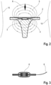
- the endoprosthesis 2 is shown schematically as a lower leg knee implant with the primary electromechanical transducer 3 and the primary electromagnetic transducer 4 lying together in a cavity.
- the secondary electromagnetic converter coil 6 is as in 1 lying orthogonal to the electromagnetic waves 5 arranged.
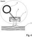
- FIG. 3 shows a ceramic-encased secondary electromagnetic transducer coil 6, the ceramic upper and lower halves being inertly connected via a soldering or adhesive zone and being biologically impermeable.
- a nerve 9 is symbolized schematically by the horizontal lines.
- the porous shaped body 7 is positioned in its immediate vicinity.
- the shaped body 7 is connected to the secondary electromagnetic converter coil 6 via the coil ends 8 .
- Neural tissue has grown into it and thus forms a permanent neural interface between the neural tissue and the secondary electromagnetic transducer coil 6.
- an interposed transducer unit can convert the AC voltage into a DC voltage directed, to be provided.
- the coil ends 8 can also be regarded as fabric electrodes themselves, directly or indirectly via the porous molded body.
- the electromagnetic converter coil 6 can be interconnected with an energy store and a signal generator, which always generates a similar signal as a biofeedback signal from an irregular biofeedback signal, which can only differ in frequency or amplitude.
Landscapes
- Health & Medical Sciences (AREA)
- General Health & Medical Sciences (AREA)
- Life Sciences & Earth Sciences (AREA)
- Veterinary Medicine (AREA)
- Engineering & Computer Science (AREA)
- Biomedical Technology (AREA)
- Animal Behavior & Ethology (AREA)
- Public Health (AREA)
- Heart & Thoracic Surgery (AREA)
- Cardiology (AREA)
- Orthopedic Medicine & Surgery (AREA)
- Nuclear Medicine, Radiotherapy & Molecular Imaging (AREA)
- Radiology & Medical Imaging (AREA)
- Neurology (AREA)
- Neurosurgery (AREA)
- Oral & Maxillofacial Surgery (AREA)
- Vascular Medicine (AREA)
- Transplantation (AREA)
- Rehabilitation Therapy (AREA)
- Prostheses (AREA)
Description
- Die Erfindung betrifft ein Prothesensystem zur vollständigen oder teilweisen Implantation in einen menschlichen Körper.
- Bei endoprothetischen Implantationen im Knie-, Hüft- und Schultergelenkbereich sowie bei Totalrevisionen, z. B. des kompletten Oberschenkelknochens, gehen in nicht wenigen Fällen unweigerlich die vorherigen neuronalen Anbindungen an das Knochen- und Muskelgewebe in Gestalt der Propriozeptoren verloren.
- Als Propriozeptoren bezeichnet man Mechanorezeptoren, welche die Wahrnehmung der Lage, Kraft, Stellung und Bewegung des Körpers im Raum gewährleisten. Durch sie gelangen Informationen über Muskelspannung, Muskellänge, Gelenkstellung und Bewegung zum Kleinhirn und zum Cortex, wo diese verarbeitet werden. Lokalisiert sind die Propriozeptoren in Gelenken, partizipierender Muskulatur, Sehnen, Bändern, Bindegewebe und der über den entsprechenden Gelenken liegenden Haut. So besitzt das vordere Kreuzband propriozeptive Nervenfasern, über die dem Zentralnervensystem Informationen über die Bewegungsabläufe des Kniegelenks zugeleitet werden. Mit einer Störung der Propriozeption geht eine Minderung des Koordinationsvermögens einher. Die Folge sind einerseits vorzeitiger Verschleiß des Implantats und/oder des restständigen, benachbarten knöchernen Gewebes durch nicht wahrnehmbare Fehl- und Überbelastung, sowie andererseits zusätzliche Komplikationen durch Stürze und Brüche (vor allem des schlecht heilenden Oberschenkelhalses) aufgrund des geminderten Koordinationsvermögens besonders bei älteren, unter Osteoporose leidenden Patienten.
- Das Prinzip der Neurostimulation an sich ist seit Jahrzehnten Gegenstand der Forschung und wird bereits in vielen klinischen Bereichen angewendet. Bekannt sind verschiedenste Formen der Neurostimulation über externe Eingriffe, neuronale Schrittmacher, etc. Diese werden vor allem im Bereich des zentralen Nervensystems eingesetzt, um pathologischen Funktionsverlusten vorzubeugen oder bei eingeschränkten oder verloren gegangenen Funktionen diese wiederherzustellen, zu verbessern und/oder zu ersetzen. Dies basiert u. a. auf der Verbesserung der Neurogenese und/oder dem Erhalt der neuronalen Verknüpfungen durch Neurostimulation und/oder Modulation vorhandener neuronaler Netzwerke.
- Im peripheren Nervensystem (Rückenmark) werden zur Therapie von chronischen Schmerzen Neuroimplantate eingesetzt. Diese Systeme umfassen temporäre Anbindung an Elektroden mit einer offenen Verbindung oder komplett implantierbare, batteriebetriebene dauerhafte Systeme, wobei auch hier eine Erneuerung der Batterie nach einigen Jahren notwendig ist. Die Stimulation erfolgt dabei unabhängig von intrinsischen, körpereigenen Signalen.
- Mit der
DE 20 2009 004 348 U1 wird eine Endoprothese mit einem integrierten Lockerungssensor beschrieben. Gemäß der offenbarten Anordnung umfasst das Lockerungsmesssystem einen an einer Feder aufgehängten bzw. fixierten, freibeweglichen ferromagnetischen Massenschwinger, der eine anliegende Membran zum Schwingen anregen kann, Desweiteren kann auch ein Piezoelement mit geschalteter Spule und Kapazität direkt an eine anliegende Membran angekoppelt werden, welche wiederum über die Endoprothese in Schwingung versetzt werden kann. Die sogenannten Lockerungssensoren lassen sich dabei einzeln ansprechen, sofern deren Eigenfrequenzen in ausreichendem Maße voneinander abweicht. Diese Systeme sind nur von außen (ex vivo) über Spulen anregbar und oder auslesbar. Ein biomechanisch-neurobiologischer Schwingkreis über eine natürlich, nicht normierte und wechselnde Endoprothesenbelastung z. B. beim Laufen, Springen oder Treppen gehen etc. ist nicht vorgesehen. - Die
US 2013/0079673 A1 offenbart einen orthopädischen Messeinsatz mit sterilem Gehäuse, der Teil einer Gelenkprothese oder eines entsprechend präparierten Gelenkknochens sein kann. Mit dem Messeinsatz können verschiedenste Bewegungs- und Belastungsparameter an der Gelenkprothese erfasst werden. Im Gehäuse ist eine elektronische Schaltung mit entsprechenden Sensoren und einer Energiequelle aufgenommen. Je nach verwendeten Sensoren könne Kräfte, Wege, Beschleunigungen, Viskositäten, pH-Werte oder Temperaturen erfasst werden. Die ermittelten Daten können mittels Antenne und Übertragungselektronik extern erfasst und aufgezeichnet werden. Die Energiequelle kann drahtlos, über elektromagnetische Kopplung wieder aufgeladen werden. - In der
europäischen Patentanmeldung EP 3 231 360 A1 wird eine Prothesenkomponente, bestehend aus einem Sensor und weiteren elektronischen Komponenten zur Energiespeicherung, Energieübertragung, selektiver Signalübermittling und Visualisierung beschrieben. Mit diesem System soll es möglich sein, die spezifische Bewegungsweise von Prothesenbestandteilen zueinander (z. B. in einem Knieimplantat) aufzuzeichnen. Diese Daten sollen zu ihrer Intepretation nach ausserhalb des Körpers übermittelt werden. - Der Erfindung liegt die Aufgabe zugrunde, eine Möglichkeit anzugeben, wodurch fehlendes oder fehlgeleitetes neuronales Feedback nach einer endoprothetischen Implantation neu und komplementär erzeugt werden kann.
- Erfindungsgemäß wird die Aufgabe gelöst durch ein Prothesensystem, bestehend aus einer Prothese und einer von dieser Prothese räumlich getrennten, als bioelektrischer Wandler wirkenden elektromagnetischen Wandlerspule mit Spulenenden, wobei an oder in der Prothese ein primärer elektromechanischer Wandler mit einem direkt gekoppelten primären elektromagnetischen Wandler zur Wandlung von mechanischer Energie in elektromagnetische Wellen, hervorgerufen durch Bewegungs-, Kraft-, Druck- und Belastungswechsel wirkend an oder in der Prothese, angeordnet ist und die davon räumlich getrennten Spulenenden der die elektromagnetischen Wellen in elektrische Signale wandelnden sekundären elektromagnetischen Wandlerspule als Elektroden in einem keramischen oder kunststoffbasierten Formkörper, der elektrisch nicht leitend und vorzugsweise offenporig ist, angeordnet sind.
- Der primäre elektromechanische Wandler und der primäre elektromagnetische Wandler können dabei in einer Baukomponente vereinigt oder räumlich getrennt angeordnet sein.
- Eine bevorzugte Ausführungsform besteht darin, dass der primäre elektromechanische Wandler in der Prothese ein Piezoelement ist, wobei das auf Bewegungs- und Belastungswechsel reagierende Piezoelement elektrische Spannungssignale erzeugt, welche der angekoppelte primäre elektromagnetische Wandler in ein elektromagnetisches Wechselfeld wandelt.
- Vorteilhaft ist es, wenn die sekundäre elektromagnetische Wandlerspule keramisch und elektrisch nicht leitend eingehaust ist.
- Um nach der erfolgten Implantation ein selbständiges Hineinwachsen von neuronalem Gewebe in den Formkörper zu stimulieren, ist es von Vorteil, wenn die Poren des Formkörpers mit aktiven oder elektrisch aktivierbaren Signalstoffen und/oder einer biologischen Matrix versehen werden. Das Hineinwachsen von neuronalem Gewebe in den Formkörper schafft so eine dauerhafte Signalschnittstelle zwischen neuronalem Gewebe und der über die Spulenenden verbundenen elektromagnetischen Wandlerspule. Der offenporige Formkörper kann dabei räumlich getrennt von der sekundären elektromagnetischen Wandlerspule oder als Bestandteil des Housing der sekundären elektromagnetischen Wandlerspule angeordnet sein.
- Weiterhin kann es von Vorteil sein, wenn die sekundäre elektromagnetische Wandlerspule als Trigger mit einem Verstärkermodul gekoppelt wird.
- Weitere vorteilhafte Ausführungen ergeben sich dadurch, dass die sekundäre elektromagnetische Wandlerspule einen integrierten Wechsel-/Gleichspannungsrichter aufweist oder die elektromagnetische Wandlerspule mit einem Energiespeicher und einem Signalgenerator, der aus einem unregelmäßigen Biofeedbacksignal ein immer gleichartiges Signal als Biofeedbacksignal generiert, welches nur in der Frequenz oder Amplitude differiert, in Verbindung steht.
- Nach erfolgter Implantation der Prothese ist die keramisch eingehauste sekundäre elektromagnetische Wandlerspule örtlich in die Reichweite der durch den primären elektromagnetischen Wandler erzeugten elektromagnetischen Wellen zu platzieren. Damit ein erfolgreiches Biofeedbacksystem mit dem erfindungsgemäßen Prothesensystem aufgebaut werden kann, sollte der Formkörper in unmittelbarer Nähe zu einem Nerv positioniert werden, damit möglichst schnell die dauerhafte Signalschnittstelle zwischen dem neuronalen Gewebe und der sekundären elektromagnetischen Wandlerspule entstehen kann.
- Ein besonderer Vorteil des erfindungsgemäßen Prothesensystems besteht darin, dass eine direkte bioelektrische, energieautarke und lebenslange Verbindung zwischen dem Implantatgewebebereich und dem neuronalen System entsteht. Das vegetative System kann somit mittels des erfindungsgemäßen Prothesensystems Überlastungs- und Fehlverhalten direkt erfassen und durch Verhaltenskorrektur gegensteuern.
- Unter einer Prothese soll sowohl jegliches Implantat, ob geschlossenes (Endoprothese) oder offenes (Zahnimplantat oder Epithesen) Implantat, als auch eine Exoprothese verstanden sein. Bei der Exoprothese sind der primäre elektromechanische und der elektromagnetische Wandler an der Grenzfläche zum Gliedmaßenstumpf angeordnet. Die neuronale Schnittstelle ist dann im Stumpf implantiert. Ziel ist dann neuronales Tiefenempfinden für eine bessere Durchblutung zu erreichen.
- Nachfolgend soll die Erfindung anhand von Ausführungsbeispielen näher erläutert werden. Die Zeichnungen zeigen in
- Fig. 1
- ein implantiertes erfindungsgemäßes Prothesensystem in Form eines Hüftgelenksimplantats,
- Fig. 2
- ein implantiertes erfindungsgemäßes Prothesensystem in Form eines Unterschenkel-Knieimplantats,
- Fig. 3
- eine Schnittdarstellung durch eine gekapselte sekundäre elektromagnetische Wandlerspule und
- Fig. 4
- eine schematische Detaildarstellung A aus
Fig. 1 . - In
Fig. 1 sind die wesentlichen Komponenten des erfindungsgemäßen Prothesensystems 1 dargestellt. Das Prothesensystem 1 besteht dabei aus der Endoprothese 2, hier als Hüftgelenksimplantat ausgeführt, dem primären elektromechanischen Wandler 3, dem primären elektromagnetischen Wandler 4, der die elektromagnetischen Wellen 5 erzeugen kann, und der keramisch eingehausten sekundären elektromagnetischen Wandlerspule 6 sowie dem Formkörper 7 als neuronale Schnittstelle. Der primäre elektromechanische Wandler 3 ist innerhalb der Endoprothese 2 derart angeordnet, dass er energieautark intrinsische Bewegungen bzw. Belastungsunterschiede/-wechsel in Spannungsänderungen umwandelt. Intrinsisch heißt in diesem Zusammenhang aus der Bewegung der Endoprothese 2 in sich und aus sich im Muskel-Skelett-Umfeld. Dies schließt insbesondere auch die Implantat-Gewebe-Kontaktzone ein, in und an der sich Belastungswechsel als Drücke und Kräfte auf das Implantat und damit auf den eingebetteten primären elektromechanischen Wandler 3 manifestieren. Der mit dem primären elektromechanischen Wandler 3 unmittelbar in Verbindung stehende primäre elektromagnetische Wandler 4 erzeugt durch diese Spannungsänderungen die inFig. 1 schematisch dargestellten elektromagnetischen Wellen 5. Die im Wirkungsbereich dieser elektromagnetischen Wellen 5 angeordnete sekundäre elektromagnetische Wandlerspule 6, die als sekundäre Induktionsspule wirkt, detektiert diese und wandelt sie wieder in elektrische Signale. Die sekundäre elektromagnetische Wandlerspule 6 befindet sich gemäßFig. 1 außerhalb der Endoprothese 2, ist jedoch wie die Endoprothese 2 im menschlichen Körper orthogonal zu den primären elektromagnetischen Wellen 5 positioniert und implantiert. Die rückgewandelten elektrischen Signale der sekundären elektromagnetischen Wandlerspule 6 werden über die Spulenenden 8 in den porösen Formkörper 7 eingeleitet. Der Formkörper 7 sollte möglichst in der Nähe eines Nervs 9 implantiert werden (sieheFig. 4 ). Die Poren des Formkörpers 7 kann man mit einem biochemischen, signaltransduktiven Stoff befüllen, der für sich neuroaktiv sein kann, aber auch einerseits über bioelektrische Impulse aktivierbar ist und andererseits so signaltransduktiv wirkt, dass vom nächstgelegenen Nerv 9 neuronale Zellen und Gewebe in Richtung des Formkörpers 6 wachsen und sich so induktiv eine neuronale, bioelektrische Schnittstelle bildet. Dies kann auch allein oder in Kombination mit Scaffolds/Matrixproteinen (z. B. biokompatiblen Polymeren, Kollagenfasern) zur Verbesserung der Gewebegeneration erfolgen. Zusätzlich kann die Formgebung des Scaffolds verletzten Neuronen als "Leitbahnen" bei der Regeneration dienen und zusätzlich mit Zellen besiedelt werden, welche die neuronale bzw. Gewebegeneration unterstützen (z. B. Schwannsche Zellen, mesenchymale Stammzellen). Die elektromagnetische Wandlerspule 6 sollte keramisch ummantelt sein, um an der Oberfläche entstehende Wirbelströme und Felder in der Nähe des Nervs 9 zu verhindern. - In
Fig. 2 ist die Endoprothese 2 schematisch als Unterschenkel-Knieimplantat mit dem primären elektromechanischen Wandler 3 und dem primären elektromagnetischen Wandler 4, gemeinsam in einer Kavität liegend, dargestellt. Auch hier ist wieder die sekundäre elektromagnetische Wandlerspule 6 wie inFig. 1 liegend orthogonal zu den elektromagnetischen Wellen 5 angeordnet. -
Fig. 3 zeigt eine keramisch ummantelte sekundäre elektromagnetische Wandlerspule 6, wobei die keramischen Ober- und Unterhälften über eine Lot- oder Klebezone inert verbunden und biologisch dicht sind. - In
Fig. 4 ist ein Nerv 9 schematisch durch die waagerechten Linien symbolisiert. In seiner unmittelbaren Nähe ist der poröse Formkörper 7 positioniert. Über die Spulenenden 8 ist der Formkörper 7 mit der sekundären elektromagnetischen Wandlerspule 6 verbunden. In den Formkörper 7 ist bereits gemäßFig. 4 neuronales Gewebe hineingewachsen und bildet so eine dauerhafte neuronale Schnittstelle zwischen neuronalem Gewebe und sekundärer elektromagnetischer Wandlerspule 6. Zwischen Spulenenden 8 und elektromagnetischer Wandlerspule 6 kann eine zwischengeschaltete Wandlereinheit, die die Wechselspannung in eine Gleichspannung richtet, vorgesehen werden. Die Spulenenden 8 können für sich auch direkt oder über den porösen Formkörper indirekt als Gewebeelektroden angesehen werden. - Ferner kann die elektromagnetische Wandlerspule 6 mit einem Energiespeicher und einem Signalgenerator, der aus einem unregelmäßigen Biofeedbacksignal ein immer gleichartiges Signal als Biofeedbacksignal generiert, welches nur in der Frequenz oder Amplitude differieren kann, verschaltet sein.
-
- 1
- Prothesensystem
- 2
- Endoprothese
- 3
- primärer elektromechanischer Wandler
- 4
- primärer elektromagnetischer Wandler
- 5
- elektromagnetische Wellen
- 6
- sekundäre elektromagnetische Wandlerspule
- 7
- Formkörper
- 8
- Spulenenden
- 9
- Nerv
Claims (14)
- Prothesensystem (1), bestehend aus einer Prothese (2) und einer von der Prothese (2) räumlich getrennten, als bioelektrischer Wandler wirkenden eingehausten elektromagnetischen Wandlerspule (6) mit Spulenenden (8), wobei an oder in der Prothese (2) ein primärer elektromechanischer Wandler (3) mit einem direkt gekoppelten primären elektromagnetischen Wandler (4) zur Wandlung von mechanischer Energie in elektromagnetische Wellen (5), hervorgerufen durch Bewegungs-, Kraft-, Druck- und Belastungswechsel wirkend an oder in der Prothese (2), angeordnet ist, dadurch gekennzeichnet, dass die davon räumlich getrennten Spulenenden (8) der die elektromagnetischen Wellen (5) in elektrische Signale wandelnden sekundären elektromagnetischen Wandlerspule (6) als Elektroden in einem keramischen oder kunststoffbasierten Formkörper (7), der elektrisch nicht leitend ist, angeordnet sind.
- Prothesensystem (1) nach Anspruch 1, dadurch gekennzeichnet, dass der primäre elektromechanische Wandler (3) ein Piezoelement ist, wobei das auf Bewegungs- und Belastungswechsel reagierende Piezoelement elektrische Spannungssignale erzeugt, welche der angekoppelte primäre elektromagnetische Wandler (4) in ein primäres elektromagnetisches Wechselfeld wandelt.
- Prothesensystem (1) nach Anspruch 1, dadurch gekennzeichnet, dass der primäre elektromechanische Wandler (3) und der primäre elektromagnetische Wandler (4) in einer Baukomponente vereinigt oder räumlich getrennt angeordnet sind.
- Prothesensystem (1) nach Anspruch 1, dadurch gekennzeichnet, dass der Formkörper (7) offenporig ausgebildet ist und die Poren des Formkörpers (7) mit aktiven oder elektrisch aktivierbaren Signalstoffen und/oder einer biologischen Matrix versehen sind, die nach Implantation des Formkörpers (7) ein selbständiges Hineinwachsen von neuronalem Gewebe in den Formkörper (7) stimulieren, sodass eine dauerhafte Signalschnittstelle zwischen neuronalem Gewebe und sekundärer elektromagnetischer Wandlerspule (6) ausgebildet ist.
- Prothesensystem (1) nach Anspruch 1 bis 4, dadurch gekennzeichnet, dass der Formkörper (7) räumlich getrennt von der sekundären elektromagnetischen Wandlerspule (6) oder als Bestandteil der sekundären elektromagnetischen Wandlerspule (6) angeordnet ist.
- Prothesensystem (1) nach Anspruch 1, dadurch gekennzeichnet, dass die sekundäre elektromagnetische Wandlerspule (6) als Trigger mit einem Verstärkermodul gekoppelt ist.
- Prothesensystem (1) nach Anspruch 1, dadurch gekennzeichnet, dass die sekundäre elektromagnetische Wandlerspule (6) einen integrierten Wechsel-/Gleichspannungsrichter aufweist.
- Prothesensystem (1) nach Anspruch 1, dadurch gekennzeichnet, dass die sekundäre elektromagnetische Wandlerspule (6) mit einem Energiespeicher und einem Signalgenerator, der aus einem unregelmäßigen Biofeedbacksignal ein immer gleichartiges Signal als Biofeedbacksignal generiert, welches nur in der Frequenz oder Amplitude differiert, in Verbindung stehend angeordnet ist.
- Prothesensystem (1) nach einem der vorhergehenden Ansprüche zur Implantation in einen menschlichen Körper, dadurch gekennzeichnet, dass nach durchgeführter Implantation des Prothesensystems (1) die keramisch eingehauste sekundäre elektromagnetische Wandlerspule (6) in der Reichweite der durch den primären elektromagnetischen Wandler (4) erzeugten primären elektromagnetischen Wellen (5) und der Formkörper (7) in unmittelbarer Nähe zu einem Nerv (9) positioniert sind.
- Prothesensystem (1) nach Anspruch 9, dadurch gekennzeichnet, dass die von der sekundären elektromagnetischen Wandlerspule (6) über die Spulenenden (8) gelieferten bioelektrischen Feedbacksignale als bioelektrisch-neuronales Feedback aus der Prothese (2) wieder für das vegetative System zur Verfügung stehen.
- Prothesensystem (1) nach einem der vorhergehenden Ansprüche, dadurch gekennzeichnet, dass die elektromagnetische Wandlerspule (6) keramisch eingehaust ist.
- Prothesensystem (1) nach einem der vorhergehenden Ansprüche, dadurch gekennzeichnet, dass die Prothese (2) eine Endoprothese ist.
- Prothesensystem (1) nach einem der Ansprüche 1 bis 11, dadurch gekennzeichnet, dass die Prothese eine Exoprothese ist, wobei der primäre elektromechanische Wandler (3) und der elektromagnetische Wandler (4) an der Grenzfläche zum Gliedmaßenstumpf angeordnet sind und der Formkörper (7) im Stumpf implantiert angeordnet ist.
- Prothesensystem (1) nach einem der vorhergehenden Ansprüche, dadurch gekennzeichnet, dass der Formkörper (7) aus einem keramischen oder kunststoffbasierten Material gefertigt ist.
Applications Claiming Priority (2)
| Application Number | Priority Date | Filing Date | Title |
|---|---|---|---|
| DE102018106945.6A DE102018106945B3 (de) | 2018-03-23 | 2018-03-23 | Endoprothesensystem |
| PCT/DE2019/100262 WO2019179578A1 (de) | 2018-03-23 | 2019-03-20 | Prothesensystem |
Publications (2)
| Publication Number | Publication Date |
|---|---|
| EP3768196A1 EP3768196A1 (de) | 2021-01-27 |
| EP3768196B1 true EP3768196B1 (de) | 2022-03-16 |
Family
ID=65638514
Family Applications (1)
| Application Number | Title | Priority Date | Filing Date |
|---|---|---|---|
| EP19722780.4A Not-in-force EP3768196B1 (de) | 2018-03-23 | 2019-03-20 | Prothesensystem |
Country Status (3)
| Country | Link |
|---|---|
| EP (1) | EP3768196B1 (de) |
| DE (2) | DE102018106945B3 (de) |
| WO (1) | WO2019179578A1 (de) |
Families Citing this family (2)
| Publication number | Priority date | Publication date | Assignee | Title |
|---|---|---|---|---|
| CN112255109B (zh) * | 2020-11-27 | 2025-07-15 | 浙江臻行科技有限公司 | 力学性能测试平台 |
| CN115252242B (zh) * | 2022-08-01 | 2025-05-13 | 上海交通大学 | 一种假肢手回撤反射控制系统及方法 |
Family Cites Families (4)
| Publication number | Priority date | Publication date | Assignee | Title |
|---|---|---|---|---|
| US7190273B2 (en) | 2003-07-11 | 2007-03-13 | Depuy Products, Inc. | Joint endoprosthesis with ambient condition sensing |
| DE202009004348U1 (de) | 2009-03-27 | 2009-06-10 | Bader, Rainer, PD Dr.med. Dipl.-Ing. | Vorrichtung zur In-situ-Messung der Verankerungsfestigkeit von Endoprothesen |
| US9161717B2 (en) * | 2011-09-23 | 2015-10-20 | Orthosensor Inc. | Orthopedic insert measuring system having a sealed cavity |
| US10420666B2 (en) * | 2013-04-08 | 2019-09-24 | Elwha Llc | Apparatus, system, and method for controlling movement of an orthopedic joint prosthesis in a mammalian subject |
-
2018
- 2018-03-23 DE DE102018106945.6A patent/DE102018106945B3/de not_active Expired - Fee Related
-
2019
- 2019-03-20 WO PCT/DE2019/100262 patent/WO2019179578A1/de not_active Ceased
- 2019-03-20 DE DE112019001494.3T patent/DE112019001494A5/de not_active Withdrawn
- 2019-03-20 EP EP19722780.4A patent/EP3768196B1/de not_active Not-in-force
Also Published As
| Publication number | Publication date |
|---|---|
| DE102018106945B3 (de) | 2019-03-28 |
| WO2019179578A1 (de) | 2019-09-26 |
| DE112019001494A5 (de) | 2020-12-10 |
| EP3768196A1 (de) | 2021-01-27 |
Similar Documents
| Publication | Publication Date | Title |
|---|---|---|
| EP3768370B1 (de) | System zur knochenregeneration | |
| US20220031479A1 (en) | Method And System For Providing Proprioceptive Feedback And Functionality Mitigating Limb Pathology | |
| AU2016289954B2 (en) | Spinal implant system and method | |
| EP2451385B1 (de) | Implantierbare medizinische vorrichtung | |
| EP1492591B1 (de) | Vorrichtung zur förderung des knochenwachstums, insbesondere zur osteosynthese von knochenfragmenten und/oder fixation von knochenfrakturen | |
| Weir et al. | Implantable myoelectric sensors (IMESs) for intramuscular electromyogram recording | |
| Bhadra et al. | Implanted stimulators for restoration of function in spinal cord injury | |
| US20220304810A1 (en) | Method for lubricating an artificial contacting surface | |
| CLIPPINGER et al. | Afferent sensory feedback for lower extremity prosthesis. | |
| DE112008001669T5 (de) | Gerillte Elektrode und drahtloses Mikrotranspondersystem | |
| WO2015061453A1 (en) | Peripheral neural interface via nerve regeneration to distal tissues | |
| US12594172B2 (en) | System and method for implantable muscle interface | |
| US20080228240A1 (en) | Long Term Bi-Directional Axon-Electronic Communication System | |
| EP3768196B1 (de) | Prothesensystem | |
| EP3067016A1 (de) | Implantierbare medizinische vorrichtung zum schmieren einer künstlichen kontaktfläche | |
| DE102014109683B4 (de) | Vorrichtung zur Detektion einer Lockerung und/oder Abnutzung einer Endoprothese | |
| US9937064B2 (en) | Osseointegrated neural interface and method | |
| US20140371854A1 (en) | Adjustable elastic antagonist muscle replacement mechanism | |
| US11020216B2 (en) | Adjustable elastic antagonist muscle replacement mechanism |
Legal Events
| Date | Code | Title | Description |
|---|---|---|---|
| STAA | Information on the status of an ep patent application or granted ep patent |
Free format text: STATUS: UNKNOWN |
|
| STAA | Information on the status of an ep patent application or granted ep patent |
Free format text: STATUS: THE INTERNATIONAL PUBLICATION HAS BEEN MADE |
|
| PUAI | Public reference made under article 153(3) epc to a published international application that has entered the european phase |
Free format text: ORIGINAL CODE: 0009012 |
|
| STAA | Information on the status of an ep patent application or granted ep patent |
Free format text: STATUS: REQUEST FOR EXAMINATION WAS MADE |
|
| 17P | Request for examination filed |
Effective date: 20201020 |
|
| AK | Designated contracting states |
Kind code of ref document: A1 Designated state(s): AL AT BE BG CH CY CZ DE DK EE ES FI FR GB GR HR HU IE IS IT LI LT LU LV MC MK MT NL NO PL PT RO RS SE SI SK SM TR |
|
| AX | Request for extension of the european patent |
Extension state: BA ME |
|
| DAV | Request for validation of the european patent (deleted) | ||
| DAX | Request for extension of the european patent (deleted) | ||
| GRAP | Despatch of communication of intention to grant a patent |
Free format text: ORIGINAL CODE: EPIDOSNIGR1 |
|
| STAA | Information on the status of an ep patent application or granted ep patent |
Free format text: STATUS: GRANT OF PATENT IS INTENDED |
|
| RIC1 | Information provided on ipc code assigned before grant |
Ipc: A61F 2/48 20060101ALI20210924BHEP Ipc: A61F 2/36 20060101ALI20210924BHEP Ipc: A61F 2/30 20060101ALI20210924BHEP Ipc: A61N 1/36 20060101ALI20210924BHEP Ipc: A61N 1/05 20060101ALI20210924BHEP Ipc: A61F 2/32 20060101AFI20210924BHEP |
|
| INTG | Intention to grant announced |
Effective date: 20211019 |
|
| GRAS | Grant fee paid |
Free format text: ORIGINAL CODE: EPIDOSNIGR3 |
|
| GRAA | (expected) grant |
Free format text: ORIGINAL CODE: 0009210 |
|
| STAA | Information on the status of an ep patent application or granted ep patent |
Free format text: STATUS: THE PATENT HAS BEEN GRANTED |
|
| AK | Designated contracting states |
Kind code of ref document: B1 Designated state(s): AL AT BE BG CH CY CZ DE DK EE ES FI FR GB GR HR HU IE IS IT LI LT LU LV MC MK MT NL NO PL PT RO RS SE SI SK SM TR |
|
| REG | Reference to a national code |
Ref country code: GB Ref legal event code: FG4D Free format text: NOT ENGLISH |
|
| REG | Reference to a national code |
Ref country code: CH Ref legal event code: EP Ref country code: DE Ref legal event code: R096 Ref document number: 502019003737 Country of ref document: DE |
|
| REG | Reference to a national code |
Ref country code: IE Ref legal event code: FG4D Free format text: LANGUAGE OF EP DOCUMENT: GERMAN |
|
| REG | Reference to a national code |
Ref country code: AT Ref legal event code: REF Ref document number: 1475377 Country of ref document: AT Kind code of ref document: T Effective date: 20220415 |
|
| RAP4 | Party data changed (patent owner data changed or rights of a patent transferred) |
Owner name: FRAUNHOFER-GESELLSCHAFT ZUR FOERDERUNG DER ANGEWANDTEN FORSCHUNG E.V. |
|
| PGFP | Annual fee paid to national office [announced via postgrant information from national office to epo] |
Ref country code: DE Payment date: 20220330 Year of fee payment: 4 |
|
| REG | Reference to a national code |
Ref country code: LT Ref legal event code: MG9D |
|
| REG | Reference to a national code |
Ref country code: NL Ref legal event code: MP Effective date: 20220316 |
|
| PG25 | Lapsed in a contracting state [announced via postgrant information from national office to epo] |
Ref country code: SE Free format text: LAPSE BECAUSE OF FAILURE TO SUBMIT A TRANSLATION OF THE DESCRIPTION OR TO PAY THE FEE WITHIN THE PRESCRIBED TIME-LIMIT Effective date: 20220316 Ref country code: RS Free format text: LAPSE BECAUSE OF FAILURE TO SUBMIT A TRANSLATION OF THE DESCRIPTION OR TO PAY THE FEE WITHIN THE PRESCRIBED TIME-LIMIT Effective date: 20220316 Ref country code: NO Free format text: LAPSE BECAUSE OF FAILURE TO SUBMIT A TRANSLATION OF THE DESCRIPTION OR TO PAY THE FEE WITHIN THE PRESCRIBED TIME-LIMIT Effective date: 20220616 Ref country code: LT Free format text: LAPSE BECAUSE OF FAILURE TO SUBMIT A TRANSLATION OF THE DESCRIPTION OR TO PAY THE FEE WITHIN THE PRESCRIBED TIME-LIMIT Effective date: 20220316 Ref country code: HR Free format text: LAPSE BECAUSE OF FAILURE TO SUBMIT A TRANSLATION OF THE DESCRIPTION OR TO PAY THE FEE WITHIN THE PRESCRIBED TIME-LIMIT Effective date: 20220316 Ref country code: BG Free format text: LAPSE BECAUSE OF FAILURE TO SUBMIT A TRANSLATION OF THE DESCRIPTION OR TO PAY THE FEE WITHIN THE PRESCRIBED TIME-LIMIT Effective date: 20220616 |
|
| PG25 | Lapsed in a contracting state [announced via postgrant information from national office to epo] |
Ref country code: LV Free format text: LAPSE BECAUSE OF FAILURE TO SUBMIT A TRANSLATION OF THE DESCRIPTION OR TO PAY THE FEE WITHIN THE PRESCRIBED TIME-LIMIT Effective date: 20220316 Ref country code: GR Free format text: LAPSE BECAUSE OF FAILURE TO SUBMIT A TRANSLATION OF THE DESCRIPTION OR TO PAY THE FEE WITHIN THE PRESCRIBED TIME-LIMIT Effective date: 20220617 Ref country code: FI Free format text: LAPSE BECAUSE OF FAILURE TO SUBMIT A TRANSLATION OF THE DESCRIPTION OR TO PAY THE FEE WITHIN THE PRESCRIBED TIME-LIMIT Effective date: 20220316 |
|
| PG25 | Lapsed in a contracting state [announced via postgrant information from national office to epo] |
Ref country code: NL Free format text: LAPSE BECAUSE OF FAILURE TO SUBMIT A TRANSLATION OF THE DESCRIPTION OR TO PAY THE FEE WITHIN THE PRESCRIBED TIME-LIMIT Effective date: 20220316 |
|
| PG25 | Lapsed in a contracting state [announced via postgrant information from national office to epo] |
Ref country code: SM Free format text: LAPSE BECAUSE OF FAILURE TO SUBMIT A TRANSLATION OF THE DESCRIPTION OR TO PAY THE FEE WITHIN THE PRESCRIBED TIME-LIMIT Effective date: 20220316 Ref country code: SK Free format text: LAPSE BECAUSE OF FAILURE TO SUBMIT A TRANSLATION OF THE DESCRIPTION OR TO PAY THE FEE WITHIN THE PRESCRIBED TIME-LIMIT Effective date: 20220316 Ref country code: RO Free format text: LAPSE BECAUSE OF FAILURE TO SUBMIT A TRANSLATION OF THE DESCRIPTION OR TO PAY THE FEE WITHIN THE PRESCRIBED TIME-LIMIT Effective date: 20220316 Ref country code: PT Free format text: LAPSE BECAUSE OF FAILURE TO SUBMIT A TRANSLATION OF THE DESCRIPTION OR TO PAY THE FEE WITHIN THE PRESCRIBED TIME-LIMIT Effective date: 20220718 Ref country code: ES Free format text: LAPSE BECAUSE OF FAILURE TO SUBMIT A TRANSLATION OF THE DESCRIPTION OR TO PAY THE FEE WITHIN THE PRESCRIBED TIME-LIMIT Effective date: 20220316 Ref country code: EE Free format text: LAPSE BECAUSE OF FAILURE TO SUBMIT A TRANSLATION OF THE DESCRIPTION OR TO PAY THE FEE WITHIN THE PRESCRIBED TIME-LIMIT Effective date: 20220316 Ref country code: CZ Free format text: LAPSE BECAUSE OF FAILURE TO SUBMIT A TRANSLATION OF THE DESCRIPTION OR TO PAY THE FEE WITHIN THE PRESCRIBED TIME-LIMIT Effective date: 20220316 |
|
| REG | Reference to a national code |
Ref country code: CH Ref legal event code: PL |
|
| PG25 | Lapsed in a contracting state [announced via postgrant information from national office to epo] |
Ref country code: PL Free format text: LAPSE BECAUSE OF FAILURE TO SUBMIT A TRANSLATION OF THE DESCRIPTION OR TO PAY THE FEE WITHIN THE PRESCRIBED TIME-LIMIT Effective date: 20220316 Ref country code: IS Free format text: LAPSE BECAUSE OF FAILURE TO SUBMIT A TRANSLATION OF THE DESCRIPTION OR TO PAY THE FEE WITHIN THE PRESCRIBED TIME-LIMIT Effective date: 20220716 Ref country code: AL Free format text: LAPSE BECAUSE OF FAILURE TO SUBMIT A TRANSLATION OF THE DESCRIPTION OR TO PAY THE FEE WITHIN THE PRESCRIBED TIME-LIMIT Effective date: 20220316 |
|
| REG | Reference to a national code |
Ref country code: BE Ref legal event code: MM Effective date: 20220331 |
|
| REG | Reference to a national code |
Ref country code: DE Ref legal event code: R097 Ref document number: 502019003737 Country of ref document: DE |
|
| PLBE | No opposition filed within time limit |
Free format text: ORIGINAL CODE: 0009261 |
|
| STAA | Information on the status of an ep patent application or granted ep patent |
Free format text: STATUS: NO OPPOSITION FILED WITHIN TIME LIMIT |
|
| PG25 | Lapsed in a contracting state [announced via postgrant information from national office to epo] |
Ref country code: MC Free format text: LAPSE BECAUSE OF FAILURE TO SUBMIT A TRANSLATION OF THE DESCRIPTION OR TO PAY THE FEE WITHIN THE PRESCRIBED TIME-LIMIT Effective date: 20220316 Ref country code: LU Free format text: LAPSE BECAUSE OF NON-PAYMENT OF DUE FEES Effective date: 20220320 Ref country code: LI Free format text: LAPSE BECAUSE OF NON-PAYMENT OF DUE FEES Effective date: 20220331 Ref country code: IE Free format text: LAPSE BECAUSE OF NON-PAYMENT OF DUE FEES Effective date: 20220320 Ref country code: DK Free format text: LAPSE BECAUSE OF FAILURE TO SUBMIT A TRANSLATION OF THE DESCRIPTION OR TO PAY THE FEE WITHIN THE PRESCRIBED TIME-LIMIT Effective date: 20220316 Ref country code: CH Free format text: LAPSE BECAUSE OF NON-PAYMENT OF DUE FEES Effective date: 20220331 |
|
| 26N | No opposition filed |
Effective date: 20221219 |
|
| PG25 | Lapsed in a contracting state [announced via postgrant information from national office to epo] |
Ref country code: SI Free format text: LAPSE BECAUSE OF FAILURE TO SUBMIT A TRANSLATION OF THE DESCRIPTION OR TO PAY THE FEE WITHIN THE PRESCRIBED TIME-LIMIT Effective date: 20220316 Ref country code: BE Free format text: LAPSE BECAUSE OF NON-PAYMENT OF DUE FEES Effective date: 20220331 |
|
| PG25 | Lapsed in a contracting state [announced via postgrant information from national office to epo] |
Ref country code: FR Free format text: LAPSE BECAUSE OF NON-PAYMENT OF DUE FEES Effective date: 20220516 |
|
| PG25 | Lapsed in a contracting state [announced via postgrant information from national office to epo] |
Ref country code: IT Free format text: LAPSE BECAUSE OF FAILURE TO SUBMIT A TRANSLATION OF THE DESCRIPTION OR TO PAY THE FEE WITHIN THE PRESCRIBED TIME-LIMIT Effective date: 20220316 |
|
| REG | Reference to a national code |
Ref country code: DE Ref legal event code: R119 Ref document number: 502019003737 Country of ref document: DE |
|
| GBPC | Gb: european patent ceased through non-payment of renewal fee |
Effective date: 20230320 |
|
| PG25 | Lapsed in a contracting state [announced via postgrant information from national office to epo] |
Ref country code: GB Free format text: LAPSE BECAUSE OF NON-PAYMENT OF DUE FEES Effective date: 20230320 |
|
| PG25 | Lapsed in a contracting state [announced via postgrant information from national office to epo] |
Ref country code: GB Free format text: LAPSE BECAUSE OF NON-PAYMENT OF DUE FEES Effective date: 20230320 Ref country code: DE Free format text: LAPSE BECAUSE OF NON-PAYMENT OF DUE FEES Effective date: 20231003 |
|
| PG25 | Lapsed in a contracting state [announced via postgrant information from national office to epo] |
Ref country code: MK Free format text: LAPSE BECAUSE OF FAILURE TO SUBMIT A TRANSLATION OF THE DESCRIPTION OR TO PAY THE FEE WITHIN THE PRESCRIBED TIME-LIMIT Effective date: 20220316 Ref country code: CY Free format text: LAPSE BECAUSE OF FAILURE TO SUBMIT A TRANSLATION OF THE DESCRIPTION OR TO PAY THE FEE WITHIN THE PRESCRIBED TIME-LIMIT Effective date: 20220316 |
|
| PG25 | Lapsed in a contracting state [announced via postgrant information from national office to epo] |
Ref country code: HU Free format text: LAPSE BECAUSE OF FAILURE TO SUBMIT A TRANSLATION OF THE DESCRIPTION OR TO PAY THE FEE WITHIN THE PRESCRIBED TIME-LIMIT; INVALID AB INITIO Effective date: 20190320 |
|
| PG25 | Lapsed in a contracting state [announced via postgrant information from national office to epo] |
Ref country code: TR Free format text: LAPSE BECAUSE OF FAILURE TO SUBMIT A TRANSLATION OF THE DESCRIPTION OR TO PAY THE FEE WITHIN THE PRESCRIBED TIME-LIMIT Effective date: 20220316 |
|
| PG25 | Lapsed in a contracting state [announced via postgrant information from national office to epo] |
Ref country code: MT Free format text: LAPSE BECAUSE OF FAILURE TO SUBMIT A TRANSLATION OF THE DESCRIPTION OR TO PAY THE FEE WITHIN THE PRESCRIBED TIME-LIMIT Effective date: 20220316 |
|
| REG | Reference to a national code |
Ref country code: AT Ref legal event code: MM01 Ref document number: 1475377 Country of ref document: AT Kind code of ref document: T Effective date: 20240320 |
|
| PG25 | Lapsed in a contracting state [announced via postgrant information from national office to epo] |
Ref country code: AT Free format text: LAPSE BECAUSE OF NON-PAYMENT OF DUE FEES Effective date: 20240320 |
|
| PGFP | Annual fee paid to national office [announced via postgrant information from national office to epo] |
Ref country code: AT Payment date: 20260410 Year of fee payment: 5 |