EP3768471B1 - Procédé de surveillance d'un système d'alimentation d'un robot - Google Patents
Procédé de surveillance d'un système d'alimentation d'un robot Download PDFInfo
- Publication number
- EP3768471B1 EP3768471B1 EP19717111.9A EP19717111A EP3768471B1 EP 3768471 B1 EP3768471 B1 EP 3768471B1 EP 19717111 A EP19717111 A EP 19717111A EP 3768471 B1 EP3768471 B1 EP 3768471B1
- Authority
- EP
- European Patent Office
- Prior art keywords
- sensor
- robot
- measurement
- supply
- signal
- Prior art date
- Legal status (The legal status is an assumption and is not a legal conclusion. Google has not performed a legal analysis and makes no representation as to the accuracy of the status listed.)
- Active
Links
Images
Classifications
-
- B—PERFORMING OPERATIONS; TRANSPORTING
- B25—HAND TOOLS; PORTABLE POWER-DRIVEN TOOLS; MANIPULATORS
- B25J—MANIPULATORS; CHAMBERS PROVIDED WITH MANIPULATION DEVICES
- B25J19/00—Accessories fitted to manipulators, e.g. for monitoring, for viewing; Safety devices combined with or specially adapted for use in connection with manipulators
- B25J19/0025—Means for supplying energy to the end effector
- B25J19/0029—Means for supplying energy to the end effector arranged within the different robot elements
-
- B—PERFORMING OPERATIONS; TRANSPORTING
- B25—HAND TOOLS; PORTABLE POWER-DRIVEN TOOLS; MANIPULATORS
- B25J—MANIPULATORS; CHAMBERS PROVIDED WITH MANIPULATION DEVICES
- B25J13/00—Controls for manipulators
- B25J13/08—Controls for manipulators by means of sensing devices, e.g. viewing or touching devices
- B25J13/087—Controls for manipulators by means of sensing devices, e.g. viewing or touching devices for sensing other physical parameters, e.g. electrical or chemical properties
-
- B—PERFORMING OPERATIONS; TRANSPORTING
- B25—HAND TOOLS; PORTABLE POWER-DRIVEN TOOLS; MANIPULATORS
- B25J—MANIPULATORS; CHAMBERS PROVIDED WITH MANIPULATION DEVICES
- B25J19/00—Accessories fitted to manipulators, e.g. for monitoring, for viewing; Safety devices combined with or specially adapted for use in connection with manipulators
- B25J19/0025—Means for supplying energy to the end effector
-
- B—PERFORMING OPERATIONS; TRANSPORTING
- B25—HAND TOOLS; PORTABLE POWER-DRIVEN TOOLS; MANIPULATORS
- B25J—MANIPULATORS; CHAMBERS PROVIDED WITH MANIPULATION DEVICES
- B25J19/00—Accessories fitted to manipulators, e.g. for monitoring, for viewing; Safety devices combined with or specially adapted for use in connection with manipulators
- B25J19/02—Sensing devices
-
- B—PERFORMING OPERATIONS; TRANSPORTING
- B25—HAND TOOLS; PORTABLE POWER-DRIVEN TOOLS; MANIPULATORS
- B25J—MANIPULATORS; CHAMBERS PROVIDED WITH MANIPULATION DEVICES
- B25J19/00—Accessories fitted to manipulators, e.g. for monitoring, for viewing; Safety devices combined with or specially adapted for use in connection with manipulators
- B25J19/06—Safety devices
-
- B—PERFORMING OPERATIONS; TRANSPORTING
- B25—HAND TOOLS; PORTABLE POWER-DRIVEN TOOLS; MANIPULATORS
- B25J—MANIPULATORS; CHAMBERS PROVIDED WITH MANIPULATION DEVICES
- B25J9/00—Program-controlled manipulators
- B25J9/16—Program controls
- B25J9/1674—Program controls characterised by safety, monitoring, diagnostic
-
- B—PERFORMING OPERATIONS; TRANSPORTING
- B25—HAND TOOLS; PORTABLE POWER-DRIVEN TOOLS; MANIPULATORS
- B25J—MANIPULATORS; CHAMBERS PROVIDED WITH MANIPULATION DEVICES
- B25J9/00—Program-controlled manipulators
- B25J9/16—Program controls
- B25J9/1694—Program controls characterised by use of sensors other than normal servo-feedback from position, speed or acceleration sensors, perception control, multi-sensor controlled systems, sensor fusion
-
- G—PHYSICS
- G01—MEASURING; TESTING
- G01R—MEASURING ELECTRIC VARIABLES; MEASURING MAGNETIC VARIABLES
- G01R31/00—Arrangements for testing electric properties; Arrangements for locating electric faults; Arrangements for electrical testing characterised by what is being tested not provided for elsewhere
- G01R31/08—Locating faults in cables, transmission lines, or networks
- G01R31/11—Locating faults in cables, transmission lines, or networks using pulse reflection methods
-
- G—PHYSICS
- G01—MEASURING; TESTING
- G01R—MEASURING ELECTRIC VARIABLES; MEASURING MAGNETIC VARIABLES
- G01R31/00—Arrangements for testing electric properties; Arrangements for locating electric faults; Arrangements for electrical testing characterised by what is being tested not provided for elsewhere
- G01R31/50—Testing of electric apparatus, lines, cables or components for short-circuits, continuity, leakage current or incorrect line connections
- G01R31/58—Testing of lines, cables or conductors
Definitions
- the invention relates to a method for monitoring a supply system of a robot, which has a robot arm and a robot hand that can be moved relative to it, the supply system having a supply cable, in particular a hose package, and a guide for the supply cable, which is routed along the robot arm to supply the robot hand.
- the supply cable is routed in such a way that compensating movements are permitted. Due to the diverse movements, different mechanical loads are exerted during a respective processing cycle.
- An example of a device for guiding a hose package along a robot is, for example, from EP 2 956 277 B1 refer to.
- the hose package In addition to mechanical loads, the hose package is also exposed to other loads, for example thermal loads or the influence of media. Due to the diverse loads, the hose package is typically a wearing part that is regularly replaced.
- WO 2012/061979 A1 discloses a method for monitoring an electrical supply line, for example in a robot, in which a test signal is fed into the supply line and evaluated with regard to fatigue of the electrical supply line.
- U1 shows a hose package for a robot with an integrated optical monitoring sensor.
- the monitoring sensor has a cladding-free optical fiber surrounded by a cladding, so that the cladding is pressed against the optical fiber when pressure is applied, thereby influencing optical signal propagation within the optical fiber.
- From the DE 10 2016 210 601 A1 discloses a method for monitoring a line of a predetermined length, which has a measuring conductor into which measuring pulses are fed. To monitor the line, reflected measuring pulses are superimposed on the fed-in measuring pulses and, depending on the superimposition, a deviation of the transit time from a target transit time is detected and a deviation from the normal state is detected.
- From the DE 10 2016 203 552 A1 discloses a method for monitoring a supply line of an industrial robot, in which a protective hose is monitored for wear by generating and evaluating a fluid pressure in the protective hose.
- the invention is based on the object of increasing the reliability of such a hose package and its service life until replacement is required.
- a number of sensors for monitoring at least one state variable of the supply system are provided for monitoring the supply system of a robot.
- the functional capability of the supply system is inferred from the values determined by the at least one sensor for the respective state variable. Expediently, a statement is made at the same time about a remaining service life.
- the particular advantage of this system can be seen in the fact that the sensors are used to actively monitor the current status, in particular in connection with a prediction of the remaining service life.
- the supply line, in particular the hose package is therefore no longer replaced at fixed maintenance intervals.
- the recorded sensor data is expediently stored and provided with a time stamp in order to track developments in the values of the state variables or the properties of the hose package and to take them into account for the prognosis. Specifically, changes or the degree of increase in changes can be determined, for example, by comparison with earlier actual values.
- the sensor data is expediently recorded continuously during operation.
- the sensor is integrated directly in the supply line, specifically in an electrical cable contained therein.
- the senor is designed as a bending sensor which, in particular, detects the bending of the hose package or of the supply line during the compensating movements.
- a bending sensor integrated into the cable As a bending sensor integrated into the cable, a bending sensor is used, for example, as is shown in FIG DE 10 2018 204 173 A1 or in the DE 10 2018 204 171 A1 is described.
- the cable itself is therefore designed as an intelligent cable, which is used to monitor its own condition and thus the supply line.
- the senor has a line element integrated in the cable. This is, for example, a wire or a pair of wires that is routed in the hose package.
- a sensor signal is fed into this line element by means of a suitable feed unit and a response signal is evaluated by an evaluation unit.
- the feed unit and evaluation unit are typically arranged on the same side of the cable.
- the feed unit is integrated, for example, in a plug of the cable or in a supply unit connected to it.
- the evaluation unit itself can be integrated into the feed-in unit or it can also be arranged remotely from it. In the latter case, the response signal, also referred to as a reflected signal, is transmitted to the evaluation unit.
- the response signal preferably arises as a result of a reflection at a "defect" that is caused, for example, by a bend.
- the propagation of the sensor signal within the line element and a reflection of parts of the sensor signal depends on the dielectricity of the line element, which in turn is influenced by the state variables. Changing temperatures, bending radii, external pressures influence the reflected response signal, which is evaluated to determine the respective value of the state variable.
- Exactly one stop signal is therefore generated for each individual measurement. There is no further evaluation of the reflected signal. As a result of the threshold value being changed between the individual measurements, different points of disturbance, which thus lead to different amplitudes in the reflection, are also recorded in a spatially resolved manner due to the different propagation times.
- this method can be regarded as a voltage-discrete time measurement method.
- the number of individual measurements is preferably more than 10, more preferably more than 20 or more than 50 and for example up to 100 or more individual measurements. From the large number of these individual measurements, a large number of stop signals are determined, which are distributed over time.
- the large number of stop signals in connection with the threshold values therefore approximately reflects the actual signal curve of the measurement signal fed in and the reflected components.
- the actual signal profile for a measurement signal that is fed in and reflected at the power end is expediently approximated from these stop signals, for example by a mathematical curve fit.
- a respective individual measurement is preferably ended as soon as a stop signal has been issued.
- a measurement dead time is specified in a preferred embodiment after a first individual measurement, during which the measurement arrangement is virtually deactivated and not in response to a stop signal reacted.
- a second individual measurement is carried out, in which the same threshold value is preferably set as in the first individual measurement.
- the measurement dead time within which no stop signal is detected, is (slightly) longer than the transit time between the start and stop signal detected in the first individual measurement. This avoids the reflected portion assigned to the first stop signal being detected in the second individual measurement. This cycle is preferably repeated several times until no further stop signal is detected. This means that the measuring dead time is adapted to the running time of the (first, second, third, etc.) stop signal recorded in the previous individual measurement, i.e. it is selected to be slightly larger, until no further stop signal is emitted up to this set threshold value.
- a signal curve is expediently measured by suitably setting the respective measuring dead time in combination with a variation of the threshold value.
- falling edges in the signal curve are also recorded as a result. Signal peaks with rising and falling edges can therefore be recorded and evaluated.
- the guide for the hose pack generally has a balancing system with a movable guide element.
- a hose clamp is often provided, to which the hose package is fixed and which performs a compensating movement relative to the robot arm.
- Such a guide element is typically movable against a spring force/restoring force, in particular mounted so that it can slide.
- the movement of the Hose package recorded and used to assess the functionality of the supply system, in particular the hose package.
- the acceleration of the hose package, the number of compensating movements, and/or the size of the compensating movement are recorded as state variables.
- the respective current environmental conditions such as temperature, vibrations, etc., are preferably additionally recorded and taken into account. All of these status variables are therefore continuously recorded during operation and are included in the assessment of the functionality and in particular in the determination of the remaining service life.
- the movement is expediently detected by means of an external sensor, which is arranged in the guide.
- This can be an electrical sensor, an optical sensor, a proximity sensor or a train sensor on a return mechanism for the compensation system.
- an external sensor is preferably arranged in addition to the sensor integrated in the cable. Sensor data from both the cable-internal sensor and the external sensor are therefore taken into account and evaluated in order to draw conclusions about the current functionality of the supply system.
- a measured value obtained from the integrated sensor is checked and verified using the measured value of the external sensor. It is therefore checked whether the data transmitted by the cable-internal sensor are plausible.
- This comparison with an external sensor for example, reduces false diagnoses by the cable's internal sensor.
- a bending sensor integrated in the cable sensor and its data are compared with the movement data from the external sensor and verified as to whether the data is plausible.
- Empirical values are stored within the comparison system, for example in tabular form, so that current status information can be derived by comparison with the comparison system.
- the comparison system is a mathematical model, which thus simulates the real system and describes it mathematically as a function of the variable state variables.
- the comparison system is expediently integrated in an evaluation unit to which the measurement data is transmitted.
- This evaluation unit is integrated, for example, in the machine control for the robot. Alternatively, however, it can also be contained in a higher-level control center or in an organizational unit that does not belong to the operator of the robot. For example, the data contained by the sensors is transmitted to the manufacturer of the hose package, which in this way monitors the functionality of the supply system in the sense of a service.
- the state variables are recorded in a large number of supply systems and transmitted to this higher-level, common and thus central evaluation point and evaluation unit.
- the collected data is then used to modify the comparison system. This enables ongoing optimization and further development of the comparison system in order to improve the accuracy of the statements.
- At least one further external data source such as the machine control of the robot itself, is preferably used and taken into account for the assessment of the functionality. Movement data can also be derived from this, for example using the control commands, and/or the measurement data from the sensors are subjected to a plausibility check.
- a method for monitoring an electrical system is provided, the electrical system being a data and/or supply system in which at least two components are connected to one another via a cable system.
- This electrical system in turn has a number of sensors, via which at least one and preferably several state variables of the electrical system and/or the environment are detected.
- the cable system has a cable with a sensor integrated therein, and an additional external sensor is also provided outside of the cable system. A measured value from this external sensor is then evaluated in addition to the sensor integrated in the cable in order to draw conclusions about the current functionality of the supply system.
- both an internal sensor and an external sensor are therefore used to check the functionality and also to predict the remaining service life.
- the external sensor is expediently used in particular for the validation and plausibility check of the data transmitted by the internal sensor.
- the electrical system generally claimed here is, for example, a (high-voltage) supply system of a motor vehicle, specifically a motor vehicle operated with an electric traction motor.
- the electrical system consists, for example, of a battery, a cable and power electronics/traction motor, with the battery being connected to the traction motor via the cable.
- the electrical system is a car transition system, for example in rail vehicles, but also in trucks, etc.. It can also be a charging system for electromobility, in which the first component is a charging station and the second component is the battery is.
- the information quality of the monitoring system based on a sensor integrated in a cable is improved.
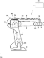
- This articulated-arm robot 1 is, for example, a multi-axis industrial robot, in particular a six-axis industrial robot.
- This has a base 8, a first segment also referred to as rocker 4, which is connected to the base 8 via a first articulated connection R1.
- the rocker 4 can be pivoted about a horizontal axis about this first articulated connection R1.
- the rocker 4 can usually be pivoted about a vertical axis relative to the base 8 .
- the rocker 4 extends approximately in the vertical direction upwards.
- a second segment generally referred to as the robot arm 2
- axis 3 is pivotally connected to the rocker 4 about a so-called "axis 3".
- a robot hand 3 is connected to the second segment 2 via a third articulated connection R3.
- a machining tool 6 is attached to the robot hand 3 .
- Such an industrial robot 1 has a total of six different degrees of freedom of movement.
- the industrial robot 1 has a supply line, which is referred to below as the supply line package 7 .
- This is guided along the robot arm 2 and is connected to the base 8 from there.
- the supply line package 7 is guided in a protective hose, at least in one section.
- the supply line package 7 together with the protective hose is also referred to below as the hose package 9 .
- a separation point for the supply line package 7 is often arranged in the area of the second articulated connection, and the hose package 9 is routed as a replaceable wearing unit up to this separation point.
- a device 10 for guiding and retrieving the hose package 9 is fastened on the robot arm 2 in the area of the second articulated connection R2.
- This device 10 includes a fastening clamp 14 in which the hose package 9 is held, in particular in a form-fitting manner, so that a restoring force exerted by the device is transmitted to the hose package 9 .
- the fastening clip 14 is guided in a (longitudinally) displaceable manner in particular counter to the spring force of a restoring spring. During operation, this therefore executes movements with the hose package.
- the hose pack 9 is additionally fixed by means of a further fastening clip 30 .
- the individual lines or the supply line package 7 emerges from the protective hose at these positions.
- the hose package 9 has an integrated line element 20, which forms an integrated sensor. This line element extends in the direction of the hose package. This line element is used specifically for detecting bends in the hose package 9.
- an external sensor 22 is also arranged, which is arranged specifically in the area of the device 10 and, in particular, detects the movements of the compensating mechanism, for example the movement of the fastening clamp 4 .
- the movements of the compensating mechanism for example the movement of the fastening clamp 4 .
- tensile forces, acceleration values, speed values, number of compensating movements, etc. are recorded.
- Both the data of the sensor 20 and that of the sensor 22 are transmitted to an evaluation unit 24 and evaluated there in order to specifically check the functionality of the hose package.
- the evaluation unit 24 preferably contains a comparison system as an image of the real system. The measurement data obtained from the two sensors 20, 22 are compared with the aid of the comparison system and current status information and, in particular, a supplementary prediction of the remaining service life are made from this.
- the relevant data for example the movement data
- This data is processed and provided with the time stamp.
- the data is then compared and correlated with additional information, for example with that of the internal sensor 20 or with additional external information, for example from the machine control. Based on this correlation and analysis of the different signals from the different information sources, especially in comparison with the comparison system, current status data with the respective service life forecasts are provided.
- the evaluation unit can be integrated in the machine control or alternatively arranged remotely.
- the signals are transmitted wirelessly, for example.
- critical states which, for example, exceed a critical limit value, are recorded and stored as impermissible states.
- An advantage of the system described here is that it is also suitable for retrofitting to existing systems.
- the data from a large number of systems used is recorded and jointly evaluated and used in the sense of a learning approach to improve the evaluation, especially the comparison system.
- the (mathematical) model that forms the comparison system for example, can thus be continuously improved will. Further error messages from the individual installed systems and their failures can also be taken into account.
- an evaluation unit is expediently provided for each system, in which the comparison system is stored. This can then be updated centrally.
Landscapes
- Engineering & Computer Science (AREA)
- Robotics (AREA)
- Mechanical Engineering (AREA)
- Physics & Mathematics (AREA)
- General Physics & Mathematics (AREA)
- Human Computer Interaction (AREA)
- Manipulator (AREA)
- Arrangements For Transmission Of Measured Signals (AREA)
Claims (12)
- Procédé de surveillance d'un système d'alimentation d'un robot, lequel robot comprend un bras de robot (2) ainsi qu'une main de robot (3) mobile par rapport à celui-ci, dans lequel le système d'alimentation comprend une cordon d'alimentation (7), en particulier un ensemble de tuyaux flexibles ainsi qu'un guidage pour le cordon d'alimentation et le cordon d'alimentation est guidée le long du bras de robot pour l'alimentation de la main de robot, dans lequel le système d'alimentation comprend en outre au moins un capteur (20, 22) pour la surveillance d'au moins une variable d'état du système d'alimentation, dans lequel, sur la base des valeurs détectées par le capteur pour la variable d'état, il est conclu à la fonctionnalité du système d'alimentation, dans lequel le cordon d'alimentation comprend un câble électrique et le capteur est intégré dans le câble électrique et le capteur est formé par un élément conducteur (20) du câble, dans lequel un signal de capteur est injecté et un signal de réponse est évalué, dans lequel une pluralité de mesures individuelles sont effectuées au cours d'un cycle de mesure, dans lequel- par mesure individuelle, le signal de mesure est injecté dans l'élément de ligne,- un signal d'arrêt est généré et la mesure individuelle est notamment terminée lorsqu'une valeur seuil prédéfinie est dépassée en raison de la composante de signal de mesure réfléchie,- un temps de transit entre l'injection du signal de mesure et le signal d'arrêt est déterminé.
- Procédé selon la revendication 1, dans lequel le capteur est conçu comme un capteur d'incurvation.
- Procédé selon la revendication 1 ou 2, dans lequel la valeur seuil est modifiée entre les mesures individuelles.
- Procédé selon l'une des revendications 1 à 3, dans lequel, après détection d'un premier signal d'arrêt lors d'une première mesure individuelle, une deuxième mesure individuelle est effectuée avec de préférence la même valeur de seuil que lors de la première mesure individuelle, dans lequel, lors de la deuxième mesure individuelle, un temps mort de mesure est prédéterminé, qui est supérieur au temps de transit pour le premier signal d'arrêt détecté lors de la première mesure individuelle, de sorte que la composante réfléchie associée au premier signal d'arrêt n'est pas détectée lors de la deuxième mesure individuelle.
- Procédé selon l'une des revendications 1 à 4, dans lequel le guide comprend un système de compensation relié au cordon d'alimentation, dans lequel le mouvement du cordon d'alimentation est détecté et utilisé pour évaluer la fonctionnalité du système d'alimentation.
- Procédé selon la revendication 5, dans lequel, au choix ou en combinaison, l'accélération du cordon d'alimentation, le nombre de mouvements de compensation ou l'amplitude de la déviation sont détectés.
- Procédé selon la revendication 5 ou 6, dans lequel le mouvement est détecté au moyen d'un capteur externe (22), qui est disposé dans ou sur le guide.
- Procédé selon l'une des revendications 1 à 7, dans lequel, en plus du capteur (20) intégré dans le câble, un capteur externe (22) est disposé à l'extérieur du câble et une valeur de mesure du capteur externe est évaluée en plus de celle du capteur intégré dans le câble, afin de conclure à la fonctionnalité actuelle du système d'alimentation.
- Procédé selon la revendication 8, dans lequel sur la base de la valeur de mesure du capteur externe une valeur de mesure obtenue par le capteur intégré est classée comme étant OK ou non OK.
- Procédé selon l'une des revendications 1 à 9, dans lequel les valeurs de mesure déterminées pour les variables d'état sont comparées à un système de comparaison et une conclusion est tirée de cette comparaison quant à la fonctionnalité.
- Procédé selon la revendication 10, dans lequel les variables d'état d'une multitude de systèmes d'alimentation sont détectées, transmises à un service d'évaluation central commun supérieur et utilisées pour une modification du système de comparaison.
- Procédé selon l'une des revendications 1 à 11, dans lequel au moins une autre source de données comme, par exemple, une commande de machine du robot, est utilisée et prise en compte pour l'évaluation de la fonctionnalité.
Applications Claiming Priority (2)
| Application Number | Priority Date | Filing Date | Title |
|---|---|---|---|
| DE102018204184.9A DE102018204184A1 (de) | 2018-03-19 | 2018-03-19 | Verfahren zur Überwachung eines Versorgungssystems eines Roboters |
| PCT/DE2019/100244 WO2019179566A1 (fr) | 2018-03-19 | 2019-03-18 | Procédé de surveillance d'un système d'alimentation d'un robot |
Publications (2)
| Publication Number | Publication Date |
|---|---|
| EP3768471A1 EP3768471A1 (fr) | 2021-01-27 |
| EP3768471B1 true EP3768471B1 (fr) | 2022-05-04 |
Family
ID=66102840
Family Applications (1)
| Application Number | Title | Priority Date | Filing Date |
|---|---|---|---|
| EP19717111.9A Active EP3768471B1 (fr) | 2018-03-19 | 2019-03-18 | Procédé de surveillance d'un système d'alimentation d'un robot |
Country Status (6)
| Country | Link |
|---|---|
| US (1) | US11897124B2 (fr) |
| EP (1) | EP3768471B1 (fr) |
| KR (1) | KR102358504B1 (fr) |
| CN (1) | CN111867787B (fr) |
| DE (1) | DE102018204184A1 (fr) |
| WO (1) | WO2019179566A1 (fr) |
Cited By (2)
| Publication number | Priority date | Publication date | Assignee | Title |
|---|---|---|---|---|
| WO2024180038A1 (fr) * | 2023-02-28 | 2024-09-06 | Bizlink Industry Germany Gmbh | Dispositif de guidage pour guider au moins une conduite qui est posée dans un tube de protection, et ensemble de rattrapage et procédé de surveillance du mouvement d'un tel tube de protection |
| WO2024180039A1 (fr) * | 2023-02-28 | 2024-09-06 | Bizlink Industry Germany Gmbh | Dispositif de guidage pour guider au moins une conduite qui est posée dans un tube de protection, comprenant un dispositif capteur doté d'un émetteur ultrasonore, et ensemble de modernisation et procédé de surveillance du mouvement d'un tel tube de protection |
Families Citing this family (6)
| Publication number | Priority date | Publication date | Assignee | Title |
|---|---|---|---|---|
| DE102018204184A1 (de) * | 2018-03-19 | 2019-09-19 | Leoni Kabel Gmbh | Verfahren zur Überwachung eines Versorgungssystems eines Roboters |
| DE102019108152A1 (de) * | 2019-03-29 | 2020-10-01 | Murrplastik Systemtechnik Gmbh | Rückführvorrichtung |
| JP7260402B2 (ja) | 2019-05-31 | 2023-04-18 | ファナック株式会社 | ケーブルの状態を学習する機械学習装置、ロボットシステム、及び機械学習方法 |
| DE102020117885B4 (de) | 2020-07-07 | 2022-12-15 | Bizlink Robotic Solutions Germany Gmbh | Überwachung eines Rückzugsystems |
| WO2023285704A1 (fr) | 2021-07-16 | 2023-01-19 | Bizlink Industry Germany Gmbh | Logement pour un guide-câble |
| DE102023201837A1 (de) * | 2023-02-28 | 2024-08-29 | Bizlink Industry Germany Gmbh | Führungsvorrichtung zur Führung von zumindest einer in einem Schutzschlauch einliegenden Leitung sowie Nachrüstset und Verfahren zur Überwachung der Bewegung eines solchen Schutzschlauches |
Family Cites Families (31)
| Publication number | Priority date | Publication date | Assignee | Title |
|---|---|---|---|---|
| DE69331433T2 (de) * | 1992-10-22 | 2002-10-02 | Advanced Interconnection Technology, Inc. | Einrichtung zur automatischen optischen Prüfung von Leiterplatten mit darin verlegten Drähten |
| US6853196B1 (en) * | 2002-04-12 | 2005-02-08 | Sandia Corporation | Method and apparatus for electrical cable testing by pulse-arrested spark discharge |
| DE10304019A1 (de) * | 2003-02-01 | 2004-11-04 | Kuka Roboter Gmbh | Verfahren zum Überwachen einer Maschine und derartige Maschine, insbesondere Roboter |
| DE102004018213A1 (de) * | 2004-04-15 | 2005-11-17 | Leoni Ag | Verfahren zur Überwachung der Verformung einer Versorgungsleitung sowie Versorgungsleitung und Vorrichtung mit einer Versorgungsleitung |
| CN100492035C (zh) | 2005-06-10 | 2009-05-27 | 清华大学 | 一种电缆安全运行监控方法 |
| KR200418443Y1 (ko) | 2006-03-28 | 2006-06-12 | 최광술 | 산업용 로봇의 케이블 조절장치 |
| WO2008037276A1 (fr) * | 2006-09-27 | 2008-04-03 | Leoni Protec Cable Systems Gmbh | Dispositif de guidage d'un tuyau souple comprenant au moins une conduite d'alimentation |
| DE102007022039B4 (de) * | 2007-05-08 | 2009-07-09 | Hochschule Mannheim | Sensoranordnung |
| US9764376B2 (en) * | 2009-04-01 | 2017-09-19 | David L. LeMieux | System for rivet fastening |
| CN101975914A (zh) | 2010-10-19 | 2011-02-16 | 华中科技大学 | 一种电力电缆绝缘状态在线监测方法及装置 |
| US9134358B2 (en) * | 2010-11-09 | 2015-09-15 | Abb Research Ltd. | Cable fatigue monitor and method thereof |
| CN103384585B (zh) * | 2010-12-01 | 2016-08-10 | Abb股份公司 | 机器人机械手系统 |
| FR3001176B1 (fr) | 2013-01-18 | 2015-02-27 | Leoni Cia Cable Systems | Dispositif de guidage et de rappel |
| DE202013105036U1 (de) * | 2013-11-08 | 2015-02-10 | Daimler Ag | Erfassungseinrichtung |
| KR20150104451A (ko) | 2014-03-05 | 2015-09-15 | 현대중공업 주식회사 | 로봇 케이블의 진단모듈을 구비한 로봇용 제어기 및 로봇 케이블의 진단방법 |
| CN103840432B (zh) | 2014-03-24 | 2016-10-05 | 北京经纬恒润科技有限公司 | 一种电机堵转检测方法和系统 |
| JP6588034B2 (ja) * | 2014-04-02 | 2019-10-09 | ハー・マジェスティ・ザ・クイーン・イン・ライト・オブ・カナダ・アズ・リプリゼンテッド・バイ・ザ・ミニスター・オブ・ナチュラル・リソーシーズ・カナダHer Majesty the Queen in Right of Canada as represented by the Minister of Natural Resources Canada | 合成ロープ又はケーブルの分析用装置及び使用方法 |
| DE102014223119B4 (de) | 2014-11-12 | 2021-01-28 | Leoni Kabel Gmbh | Datenkabel sowie Verfahren zur Herstellung eines Datenkabels |
| CN104697432B (zh) | 2015-02-04 | 2017-03-15 | 浙江大学 | 一种能实现变形自检功能的管缆 |
| DE102016203552A1 (de) * | 2016-03-03 | 2017-09-07 | Kuka Roboter Gmbh | Verfahren zum Überwachen einer Versorgungsleitung eines Industrieroboters |
| CN106042004B (zh) | 2016-05-30 | 2018-09-11 | 京东方科技集团股份有限公司 | 一种磨损报警装置和方法 |
| DE102016210601A1 (de) | 2016-06-15 | 2017-12-21 | Leoni Kabel Gmbh | Verfahren zur Überwachung einer Leitung und Messanordnung mit einer Leitung |
| DE102016210603B4 (de) * | 2016-06-15 | 2020-01-16 | Leoni Kabel Gmbh | Vorrichtung, Versorgungsleitung für eine solche, Sensorleitung und Verfahren zur Torsionsmessung |
| DE102016210615A1 (de) | 2016-06-15 | 2017-12-21 | Leoni Kabel Gmbh | Vorrichtung, Versorgungsleitung für eine solche, Sensorleitung und Verfahren zur Torsionsmessung |
| CN107516641A (zh) | 2016-06-16 | 2017-12-26 | 上海新昇半导体科技有限公司 | 机械手臂的监控系统及监控方法 |
| JP2017226000A (ja) * | 2016-06-23 | 2017-12-28 | 株式会社ダイヘン | ケーブル監視装置および溶接ロボットシステム |
| CN110073226B (zh) | 2016-11-11 | 2022-02-01 | 莱尼电缆有限公司 | 用于监测线路的方法和测量装置 |
| CN206811974U (zh) | 2017-06-16 | 2017-12-29 | 苏州华兴致远电子科技有限公司 | 一种列车检修机器人 |
| DE102018204184A1 (de) * | 2018-03-19 | 2019-09-19 | Leoni Kabel Gmbh | Verfahren zur Überwachung eines Versorgungssystems eines Roboters |
| DE102018204173A1 (de) | 2018-03-19 | 2019-09-19 | Leoni Kabel Gmbh | Messanordnung zur Überwachung eines biegeflexiblen Strangs und biegeflexibler Strang sowie Verfahren zur Überwachung eines biegeflexiblen Strangs |
| DE102018204171A1 (de) | 2018-03-19 | 2019-09-19 | Leoni Kabel Gmbh | Messanordnung zur Überwachung eines biegeflexiblen Strangs und biegeflexibler Strang sowie Verfahren zur Überwachung eines biegeflexiblen Strangs |
-
2018
- 2018-03-19 DE DE102018204184.9A patent/DE102018204184A1/de not_active Ceased
-
2019
- 2019-03-18 WO PCT/DE2019/100244 patent/WO2019179566A1/fr not_active Ceased
- 2019-03-18 EP EP19717111.9A patent/EP3768471B1/fr active Active
- 2019-03-18 US US16/982,672 patent/US11897124B2/en active Active
- 2019-03-18 CN CN201980020205.7A patent/CN111867787B/zh active Active
- 2019-03-18 KR KR1020207029629A patent/KR102358504B1/ko not_active Expired - Fee Related
Cited By (2)
| Publication number | Priority date | Publication date | Assignee | Title |
|---|---|---|---|---|
| WO2024180038A1 (fr) * | 2023-02-28 | 2024-09-06 | Bizlink Industry Germany Gmbh | Dispositif de guidage pour guider au moins une conduite qui est posée dans un tube de protection, et ensemble de rattrapage et procédé de surveillance du mouvement d'un tel tube de protection |
| WO2024180039A1 (fr) * | 2023-02-28 | 2024-09-06 | Bizlink Industry Germany Gmbh | Dispositif de guidage pour guider au moins une conduite qui est posée dans un tube de protection, comprenant un dispositif capteur doté d'un émetteur ultrasonore, et ensemble de modernisation et procédé de surveillance du mouvement d'un tel tube de protection |
Also Published As
| Publication number | Publication date |
|---|---|
| CN111867787B (zh) | 2023-07-14 |
| KR20200128147A (ko) | 2020-11-11 |
| CN111867787A (zh) | 2020-10-30 |
| EP3768471A1 (fr) | 2021-01-27 |
| US11897124B2 (en) | 2024-02-13 |
| US20210001499A1 (en) | 2021-01-07 |
| WO2019179566A1 (fr) | 2019-09-26 |
| DE102018204184A1 (de) | 2019-09-19 |
| KR102358504B1 (ko) | 2022-02-08 |
Similar Documents
| Publication | Publication Date | Title |
|---|---|---|
| EP3768471B1 (fr) | Procédé de surveillance d'un système d'alimentation d'un robot | |
| DE102017001305B4 (de) | Fehlerdiagnosevorrichtung eines Robotersystem zum Beurteilen eines Fehlers anhand eines Kamerabildes | |
| EP3559505B1 (fr) | Système pour surveiller le fonctionnement d'une chaîne porte-câbles | |
| EP3538963B1 (fr) | Procédé pour faire fonctionner un système de surveillance d'état d'une machine vibrante et système de surveillance d'état | |
| EP3472568B1 (fr) | Dispositif, procédé et l'application d'un câble de détecteur pour la mesure de torsion | |
| DE10248298A1 (de) | Setzwerk mit Mitteln zur Kontrolle von Setzvorgängen | |
| DE10304019A1 (de) | Verfahren zum Überwachen einer Maschine und derartige Maschine, insbesondere Roboter | |
| DE102015224641A1 (de) | Verfahren zum Erkennen einer Kollision eines Roboterarms mit einem Objekt und Roboter mit einem Roboterarm | |
| DE102018008370A1 (de) | Lebensdauervorhersagegerät | |
| WO2015019285A1 (fr) | Presse à plier | |
| EP3414465B1 (fr) | Procédé d'identification de jeu à l'ouverture pour un frein de véhicule à moteur, en particulier de véhicule utilitaire, contrôleur et frein doté d'un tel système. | |
| EP1607192B1 (fr) | Méthode et système pour estimer l'usure des articulations d'un bras de robot | |
| EP1469958B1 (fr) | Outil de pose equipe de systemes de controle de processus de pose | |
| AT517886B1 (de) | Vorrichtung zum Überprüfen eines Zustandes eines Maschinenteils | |
| DE102017009046A1 (de) | Zustandsüberwachungssystem, verfahren zum bestimmen eines abnutzungsgrads, wartungssteuerungsverfahren, betriebsführungs- und sicherheitssystem und extruder | |
| EP2464495B1 (fr) | Système de diagnostic d'un dispositif comprenant des parties mobiles | |
| WO2022028828A1 (fr) | Dispositif et procédé permettant de capturer des vitesses de segments de bras d'un robot | |
| DE102013221899A1 (de) | Industrieroboter | |
| EP4326999B1 (fr) | Procédé et machine d'usinage pour déterminer l'état d'une propulsion pignon et crémaillère pour un axe de parcours | |
| DE102016004569B4 (de) | Numerische Steuervorrichtung mit Koordinatenwerterfassungsfunktion, die weder ein Skip-Signal noch eine Tastenbetätigung benötigt | |
| DE102023201837A1 (de) | Führungsvorrichtung zur Führung von zumindest einer in einem Schutzschlauch einliegenden Leitung sowie Nachrüstset und Verfahren zur Überwachung der Bewegung eines solchen Schutzschlauches | |
| DE10248299A1 (de) | Nietsetzgerät mit Zugspannungs-Messeinrichtung | |
| EP3385495B1 (fr) | Machine de travail permettant d'effectuer des travaux de forage | |
| EP0950938B1 (fr) | Méthode et dispositif pour le contrôle de qualité | |
| DE102020205095A1 (de) | Linearbewegungssystem und Überwachungseinrichtung dafür |
Legal Events
| Date | Code | Title | Description |
|---|---|---|---|
| STAA | Information on the status of an ep patent application or granted ep patent |
Free format text: STATUS: UNKNOWN |
|
| STAA | Information on the status of an ep patent application or granted ep patent |
Free format text: STATUS: THE INTERNATIONAL PUBLICATION HAS BEEN MADE |
|
| PUAI | Public reference made under article 153(3) epc to a published international application that has entered the european phase |
Free format text: ORIGINAL CODE: 0009012 |
|
| STAA | Information on the status of an ep patent application or granted ep patent |
Free format text: STATUS: REQUEST FOR EXAMINATION WAS MADE |
|
| 17P | Request for examination filed |
Effective date: 20201009 |
|
| AK | Designated contracting states |
Kind code of ref document: A1 Designated state(s): AL AT BE BG CH CY CZ DE DK EE ES FI FR GB GR HR HU IE IS IT LI LT LU LV MC MK MT NL NO PL PT RO RS SE SI SK SM TR |
|
| AX | Request for extension of the european patent |
Extension state: BA ME |
|
| RIN1 | Information on inventor provided before grant (corrected) |
Inventor name: HITZ, BASTIAN |
|
| RAP1 | Party data changed (applicant data changed or rights of an application transferred) |
Owner name: LEONI PROTEC CABLE SYSTEMS GMBH |
|
| DAV | Request for validation of the european patent (deleted) | ||
| DAX | Request for extension of the european patent (deleted) | ||
| GRAP | Despatch of communication of intention to grant a patent |
Free format text: ORIGINAL CODE: EPIDOSNIGR1 |
|
| STAA | Information on the status of an ep patent application or granted ep patent |
Free format text: STATUS: GRANT OF PATENT IS INTENDED |
|
| INTG | Intention to grant announced |
Effective date: 20211125 |
|
| GRAS | Grant fee paid |
Free format text: ORIGINAL CODE: EPIDOSNIGR3 |
|
| GRAA | (expected) grant |
Free format text: ORIGINAL CODE: 0009210 |
|
| STAA | Information on the status of an ep patent application or granted ep patent |
Free format text: STATUS: THE PATENT HAS BEEN GRANTED |
|
| AK | Designated contracting states |
Kind code of ref document: B1 Designated state(s): AL AT BE BG CH CY CZ DE DK EE ES FI FR GB GR HR HU IE IS IT LI LT LU LV MC MK MT NL NO PL PT RO RS SE SI SK SM TR |
|
| RAP3 | Party data changed (applicant data changed or rights of an application transferred) |
Owner name: BIZLINK ROBOTIC SOLUTIONS GERMANY GMBH |
|
| REG | Reference to a national code |
Ref country code: GB Ref legal event code: FG4D Free format text: NOT ENGLISH |
|
| REG | Reference to a national code |
Ref country code: CH Ref legal event code: EP |
|
| REG | Reference to a national code |
Ref country code: AT Ref legal event code: REF Ref document number: 1488532 Country of ref document: AT Kind code of ref document: T Effective date: 20220515 |
|
| REG | Reference to a national code |
Ref country code: DE Ref legal event code: R096 Ref document number: 502019004276 Country of ref document: DE |
|
| REG | Reference to a national code |
Ref country code: IE Ref legal event code: FG4D Free format text: LANGUAGE OF EP DOCUMENT: GERMAN |
|
| REG | Reference to a national code |
Ref country code: LT Ref legal event code: MG9D |
|
| REG | Reference to a national code |
Ref country code: NL Ref legal event code: MP Effective date: 20220504 |
|
| PG25 | Lapsed in a contracting state [announced via postgrant information from national office to epo] |
Ref country code: SE Free format text: LAPSE BECAUSE OF FAILURE TO SUBMIT A TRANSLATION OF THE DESCRIPTION OR TO PAY THE FEE WITHIN THE PRESCRIBED TIME-LIMIT Effective date: 20220504 Ref country code: PT Free format text: LAPSE BECAUSE OF FAILURE TO SUBMIT A TRANSLATION OF THE DESCRIPTION OR TO PAY THE FEE WITHIN THE PRESCRIBED TIME-LIMIT Effective date: 20220905 Ref country code: NO Free format text: LAPSE BECAUSE OF FAILURE TO SUBMIT A TRANSLATION OF THE DESCRIPTION OR TO PAY THE FEE WITHIN THE PRESCRIBED TIME-LIMIT Effective date: 20220804 Ref country code: NL Free format text: LAPSE BECAUSE OF FAILURE TO SUBMIT A TRANSLATION OF THE DESCRIPTION OR TO PAY THE FEE WITHIN THE PRESCRIBED TIME-LIMIT Effective date: 20220504 Ref country code: LT Free format text: LAPSE BECAUSE OF FAILURE TO SUBMIT A TRANSLATION OF THE DESCRIPTION OR TO PAY THE FEE WITHIN THE PRESCRIBED TIME-LIMIT Effective date: 20220504 Ref country code: HR Free format text: LAPSE BECAUSE OF FAILURE TO SUBMIT A TRANSLATION OF THE DESCRIPTION OR TO PAY THE FEE WITHIN THE PRESCRIBED TIME-LIMIT Effective date: 20220504 Ref country code: GR Free format text: LAPSE BECAUSE OF FAILURE TO SUBMIT A TRANSLATION OF THE DESCRIPTION OR TO PAY THE FEE WITHIN THE PRESCRIBED TIME-LIMIT Effective date: 20220805 Ref country code: FI Free format text: LAPSE BECAUSE OF FAILURE TO SUBMIT A TRANSLATION OF THE DESCRIPTION OR TO PAY THE FEE WITHIN THE PRESCRIBED TIME-LIMIT Effective date: 20220504 Ref country code: BG Free format text: LAPSE BECAUSE OF FAILURE TO SUBMIT A TRANSLATION OF THE DESCRIPTION OR TO PAY THE FEE WITHIN THE PRESCRIBED TIME-LIMIT Effective date: 20220804 |
|
| PG25 | Lapsed in a contracting state [announced via postgrant information from national office to epo] |
Ref country code: RS Free format text: LAPSE BECAUSE OF FAILURE TO SUBMIT A TRANSLATION OF THE DESCRIPTION OR TO PAY THE FEE WITHIN THE PRESCRIBED TIME-LIMIT Effective date: 20220504 Ref country code: PL Free format text: LAPSE BECAUSE OF FAILURE TO SUBMIT A TRANSLATION OF THE DESCRIPTION OR TO PAY THE FEE WITHIN THE PRESCRIBED TIME-LIMIT Effective date: 20220504 Ref country code: LV Free format text: LAPSE BECAUSE OF FAILURE TO SUBMIT A TRANSLATION OF THE DESCRIPTION OR TO PAY THE FEE WITHIN THE PRESCRIBED TIME-LIMIT Effective date: 20220504 Ref country code: IS Free format text: LAPSE BECAUSE OF FAILURE TO SUBMIT A TRANSLATION OF THE DESCRIPTION OR TO PAY THE FEE WITHIN THE PRESCRIBED TIME-LIMIT Effective date: 20220904 |
|
| PG25 | Lapsed in a contracting state [announced via postgrant information from national office to epo] |
Ref country code: SM Free format text: LAPSE BECAUSE OF FAILURE TO SUBMIT A TRANSLATION OF THE DESCRIPTION OR TO PAY THE FEE WITHIN THE PRESCRIBED TIME-LIMIT Effective date: 20220504 Ref country code: SK Free format text: LAPSE BECAUSE OF FAILURE TO SUBMIT A TRANSLATION OF THE DESCRIPTION OR TO PAY THE FEE WITHIN THE PRESCRIBED TIME-LIMIT Effective date: 20220504 Ref country code: RO Free format text: LAPSE BECAUSE OF FAILURE TO SUBMIT A TRANSLATION OF THE DESCRIPTION OR TO PAY THE FEE WITHIN THE PRESCRIBED TIME-LIMIT Effective date: 20220504 Ref country code: ES Free format text: LAPSE BECAUSE OF FAILURE TO SUBMIT A TRANSLATION OF THE DESCRIPTION OR TO PAY THE FEE WITHIN THE PRESCRIBED TIME-LIMIT Effective date: 20220504 Ref country code: EE Free format text: LAPSE BECAUSE OF FAILURE TO SUBMIT A TRANSLATION OF THE DESCRIPTION OR TO PAY THE FEE WITHIN THE PRESCRIBED TIME-LIMIT Effective date: 20220504 Ref country code: DK Free format text: LAPSE BECAUSE OF FAILURE TO SUBMIT A TRANSLATION OF THE DESCRIPTION OR TO PAY THE FEE WITHIN THE PRESCRIBED TIME-LIMIT Effective date: 20220504 Ref country code: CZ Free format text: LAPSE BECAUSE OF FAILURE TO SUBMIT A TRANSLATION OF THE DESCRIPTION OR TO PAY THE FEE WITHIN THE PRESCRIBED TIME-LIMIT Effective date: 20220504 |
|
| REG | Reference to a national code |
Ref country code: DE Ref legal event code: R097 Ref document number: 502019004276 Country of ref document: DE |
|
| PLBE | No opposition filed within time limit |
Free format text: ORIGINAL CODE: 0009261 |
|
| STAA | Information on the status of an ep patent application or granted ep patent |
Free format text: STATUS: NO OPPOSITION FILED WITHIN TIME LIMIT |
|
| PG25 | Lapsed in a contracting state [announced via postgrant information from national office to epo] |
Ref country code: AL Free format text: LAPSE BECAUSE OF FAILURE TO SUBMIT A TRANSLATION OF THE DESCRIPTION OR TO PAY THE FEE WITHIN THE PRESCRIBED TIME-LIMIT Effective date: 20220504 |
|
| 26N | No opposition filed |
Effective date: 20230207 |
|
| PG25 | Lapsed in a contracting state [announced via postgrant information from national office to epo] |
Ref country code: SI Free format text: LAPSE BECAUSE OF FAILURE TO SUBMIT A TRANSLATION OF THE DESCRIPTION OR TO PAY THE FEE WITHIN THE PRESCRIBED TIME-LIMIT Effective date: 20220504 |
|
| P01 | Opt-out of the competence of the unified patent court (upc) registered |
Effective date: 20230505 |
|
| PG25 | Lapsed in a contracting state [announced via postgrant information from national office to epo] |
Ref country code: MC Free format text: LAPSE BECAUSE OF FAILURE TO SUBMIT A TRANSLATION OF THE DESCRIPTION OR TO PAY THE FEE WITHIN THE PRESCRIBED TIME-LIMIT Effective date: 20220504 |
|
| REG | Reference to a national code |
Ref country code: CH Ref legal event code: PL |
|
| GBPC | Gb: european patent ceased through non-payment of renewal fee |
Effective date: 20230318 |
|
| REG | Reference to a national code |
Ref country code: BE Ref legal event code: MM Effective date: 20230331 |
|
| PG25 | Lapsed in a contracting state [announced via postgrant information from national office to epo] |
Ref country code: LU Free format text: LAPSE BECAUSE OF NON-PAYMENT OF DUE FEES Effective date: 20230318 |
|
| REG | Reference to a national code |
Ref country code: IE Ref legal event code: MM4A |
|
| PG25 | Lapsed in a contracting state [announced via postgrant information from national office to epo] |
Ref country code: GB Free format text: LAPSE BECAUSE OF NON-PAYMENT OF DUE FEES Effective date: 20230318 |
|
| PG25 | Lapsed in a contracting state [announced via postgrant information from national office to epo] |
Ref country code: LI Free format text: LAPSE BECAUSE OF NON-PAYMENT OF DUE FEES Effective date: 20230331 Ref country code: IT Free format text: LAPSE BECAUSE OF FAILURE TO SUBMIT A TRANSLATION OF THE DESCRIPTION OR TO PAY THE FEE WITHIN THE PRESCRIBED TIME-LIMIT Effective date: 20220504 Ref country code: IE Free format text: LAPSE BECAUSE OF NON-PAYMENT OF DUE FEES Effective date: 20230318 Ref country code: GB Free format text: LAPSE BECAUSE OF NON-PAYMENT OF DUE FEES Effective date: 20230318 Ref country code: CH Free format text: LAPSE BECAUSE OF NON-PAYMENT OF DUE FEES Effective date: 20230331 |
|
| PG25 | Lapsed in a contracting state [announced via postgrant information from national office to epo] |
Ref country code: BE Free format text: LAPSE BECAUSE OF NON-PAYMENT OF DUE FEES Effective date: 20230331 |
|
| PG25 | Lapsed in a contracting state [announced via postgrant information from national office to epo] |
Ref country code: BG Free format text: LAPSE BECAUSE OF FAILURE TO SUBMIT A TRANSLATION OF THE DESCRIPTION OR TO PAY THE FEE WITHIN THE PRESCRIBED TIME-LIMIT Effective date: 20220504 |
|
| PG25 | Lapsed in a contracting state [announced via postgrant information from national office to epo] |
Ref country code: BG Free format text: LAPSE BECAUSE OF FAILURE TO SUBMIT A TRANSLATION OF THE DESCRIPTION OR TO PAY THE FEE WITHIN THE PRESCRIBED TIME-LIMIT Effective date: 20220504 |
|
| REG | Reference to a national code |
Ref country code: AT Ref legal event code: MM01 Ref document number: 1488532 Country of ref document: AT Kind code of ref document: T Effective date: 20240318 |
|
| PG25 | Lapsed in a contracting state [announced via postgrant information from national office to epo] |
Ref country code: AT Free format text: LAPSE BECAUSE OF NON-PAYMENT OF DUE FEES Effective date: 20240318 |
|
| PG25 | Lapsed in a contracting state [announced via postgrant information from national office to epo] |
Ref country code: CY Free format text: LAPSE BECAUSE OF FAILURE TO SUBMIT A TRANSLATION OF THE DESCRIPTION OR TO PAY THE FEE WITHIN THE PRESCRIBED TIME-LIMIT; INVALID AB INITIO Effective date: 20190318 |
|
| PG25 | Lapsed in a contracting state [announced via postgrant information from national office to epo] |
Ref country code: HU Free format text: LAPSE BECAUSE OF FAILURE TO SUBMIT A TRANSLATION OF THE DESCRIPTION OR TO PAY THE FEE WITHIN THE PRESCRIBED TIME-LIMIT; INVALID AB INITIO Effective date: 20190318 |
|
| PG25 | Lapsed in a contracting state [announced via postgrant information from national office to epo] |
Ref country code: TR Free format text: LAPSE BECAUSE OF FAILURE TO SUBMIT A TRANSLATION OF THE DESCRIPTION OR TO PAY THE FEE WITHIN THE PRESCRIBED TIME-LIMIT Effective date: 20220504 |
|
| PGFP | Annual fee paid to national office [announced via postgrant information from national office to epo] |
Ref country code: DE Payment date: 20260320 Year of fee payment: 8 |
|
| PGFP | Annual fee paid to national office [announced via postgrant information from national office to epo] |
Ref country code: AT Payment date: 20260410 Year of fee payment: 5 |
|
| PGFP | Annual fee paid to national office [announced via postgrant information from national office to epo] |
Ref country code: FR Payment date: 20260324 Year of fee payment: 8 |