EP3768574B1 - Steer-by-wire architekturen - Google Patents
Steer-by-wire architekturen Download PDFInfo
- Publication number
- EP3768574B1 EP3768574B1 EP19712707.9A EP19712707A EP3768574B1 EP 3768574 B1 EP3768574 B1 EP 3768574B1 EP 19712707 A EP19712707 A EP 19712707A EP 3768574 B1 EP3768574 B1 EP 3768574B1
- Authority
- EP
- European Patent Office
- Prior art keywords
- steering
- actuator
- motor vehicle
- steer
- communication channels
- Prior art date
- Legal status (The legal status is an assumption and is not a legal conclusion. Google has not performed a legal analysis and makes no representation as to the accuracy of the status listed.)
- Active
Links
Images
Classifications
-
- B—PERFORMING OPERATIONS; TRANSPORTING
- B62—LAND VEHICLES FOR TRAVELLING OTHERWISE THAN ON RAILS
- B62D—MOTOR VEHICLES; TRAILERS
- B62D5/00—Power-assisted or power-driven steering
- B62D5/001—Mechanical components or aspects of steer-by-wire systems, not otherwise provided for in this maingroup
- B62D5/003—Backup systems, e.g. for manual steering
-
- B—PERFORMING OPERATIONS; TRANSPORTING
- B62—LAND VEHICLES FOR TRAVELLING OTHERWISE THAN ON RAILS
- B62D—MOTOR VEHICLES; TRAILERS
- B62D5/00—Power-assisted or power-driven steering
- B62D5/001—Mechanical components or aspects of steer-by-wire systems, not otherwise provided for in this maingroup
-
- B—PERFORMING OPERATIONS; TRANSPORTING
- B62—LAND VEHICLES FOR TRAVELLING OTHERWISE THAN ON RAILS
- B62D—MOTOR VEHICLES; TRAILERS
- B62D6/00—Arrangements for automatically controlling steering depending on driving conditions sensed and responded to, e.g. control circuits
- B62D6/008—Control of feed-back to the steering input member, e.g. simulating road feel in steer-by-wire applications
-
- B—PERFORMING OPERATIONS; TRANSPORTING
- B62—LAND VEHICLES FOR TRAVELLING OTHERWISE THAN ON RAILS
- B62D—MOTOR VEHICLES; TRAILERS
- B62D5/00—Power-assisted or power-driven steering
- B62D5/04—Power-assisted or power-driven steering electrical, e.g. using an electric servo-motor connected to, or forming part of, the steering gear
- B62D5/0457—Power-assisted or power-driven steering electrical, e.g. using an electric servo-motor connected to, or forming part of, the steering gear characterised by control features of the drive means as such
- B62D5/0481—Power-assisted or power-driven steering electrical, e.g. using an electric servo-motor connected to, or forming part of, the steering gear characterised by control features of the drive means as such monitoring the steering system, e.g. failures
Definitions
- the present invention relates to a steer-by-wire steering system for motor vehicles with the features of the preamble of claim 1.
- the position of the steered wheels is not directly linked to the steering wheel. There is a connection between the steering wheel and the steered wheels via electrical signals. Instead of the mechanical coupling, a steering actuator is used to position the wheels and a feedback actuator to simulate the restoring forces on the steering wheel. In order to meet the safety requirements, the steering system must be designed in such a way that functionality is always guaranteed. Mainly because of the costs involved, a suitable compromise must be found between the degree of fault tolerance and the number of redundant components.
- a steer-by-wire steering system according to the preamble of claim 1 is out DE 101 12 514 A1 known.
- A1 is a steer-by-wire steering system with a steering wheel module, a steer-by-wire control unit, a supply module and a steering actuator known as a steering module.
- the supply module has at least two voltage sources, so that a reliable energy supply to the steer-by-wire steering system according to the invention is guaranteed even if one voltage source fails.
- a redundant connection between the steer-by-wire control unit and the other modules is established via data buses.
- US 2004/0026158 A1 describes a steer-by-wire steering system with a central control unit that evaluates a driver's steering command and converts it into a control signal for the steering actuators.
- the electronics of the steering actuator and the electronics of the central control unit are connected via two data transmission lines of a steering bus system.
- the data transmission lines of the steering bus system are also connected with two independent energy sources.
- the signals from the steering sensors, which record the driver's steering command, are also transmitted to the central control unit via the data transmission lines of the redundant bus system.
- a fault-tolerant architecture for a distributed control system of a motor vehicle steering with fault-tolerant modules a wired communication bus and radio transceivers is described.
- the fault-tolerant modules communicate using the radio transceivers if communication via the wired bus is affected by an error.
- the radio modules When the radio modules are activated, they communicate via the fieldbus-based TTP/C protocol.
- a steer-by-wire steering system for motor vehicles comprising a steering actuator that acts on the steered wheels and is electronically controlled depending on a driver's steering request and a feedback actuator that transmits the effects of the road to a control, the feedback actuator and the steering actuator have a redundant power supply. If a power supply fails, the steering system can continue to work reliably.
- the feedback actuator and the steering actuator are each connected to a first power supply and a second power supply.
- the two power supplies are preferably designed in such a way that if one of the two power supplies fails, the other power supply ensures that the feedback actuator and the steering actuator continue to operate can be operated.
- two redundant motor vehicle communication channels are additionally provided, via which the feedback actuator communicates with both the motor vehicle and the steering actuator.
- Two redundant, private communication channels are provided through which the feedback actuator communicates exclusively with the steering actuator.
- Two redundant motor vehicle communication channels can be provided, via which the feedback actuator communicates with the motor vehicle, the motor vehicle communication channels and the private communication channels being designed so that the feedback actuator transmits relevant signals from the motor vehicle to the steering actuator and vice versa.
- the steering actuator communicates with the motor vehicle via the two redundant motor vehicle communication channels.
- the motor vehicle communication channels and the private communication channels between the feedback actuator and the steering actuator are designed so that the steering actuator transmits relevant signals from the motor vehicle to the feedback actuator and vice versa.
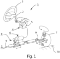
- a steer-by-wire steering system 1 is shown.
- a rotation angle sensor not shown, is attached to a steering shaft 2 and detects the driver steering torque applied by turning the steering wheel 3.
- a feedback actuator 4 is attached to the steering shaft 2, which serves to transmit the reactions from the road 70 to the steering wheel 3 and thus to give the driver feedback about the steering and driving behavior of the vehicle.
- the driver's steering request is transmitted to a control unit 5 via signal lines via the angle of rotation of the steering shaft 2 measured by the rotation angle sensor.
- the control unit 5 controls depending on the signal from the rotation angle sensor and other input variables, such as. B. vehicle speed, yaw rate and the like, an electric steering actuator 6, also called steering actuator, which controls the position of the steered wheels 7.
- the steering actuator 6 causes an axial displacement of a rack by means of a screw drive 8.
- the steered wheels 7 are connected to the rack via tie rods 9.
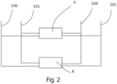
- Figure 2 shows a comparative example of a cabling architecture for a steer-by-wire steering system.
- the feedback actuator 4 communicates on two motor vehicle communication channels 100, 101 with both the motor vehicle and with the steering actuator 6. All required signals are transmitted on both vehicle communication channels 100, 101 between the motor vehicle and the steer-by-wire system 1 and between the Steering actuator 6 and the feedback actuator 4 are transmitted.
- the two motor vehicle communication channels 100, 101 are designed to be redundant. If one of the motor vehicle communication channels 100, 101 fails, the other motor vehicle communication channel 101, 100 can completely take over the communication so that the system can continue to work properly.
- a redundant power supply is provided for both the feedback actuator 4 and the steering actuator 6.
- the feedback actuator 4 and the steering actuator 6 are each connected to a first power supply 200 and a second power supply 201.
- the other, error-free power supply 201, 200 ensures that the feedback actuator 4 and the steering actuator 6 can continue to be operated.
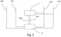
- FIG 3 shows a second cabling architecture for steer-by-wire steering as a first exemplary embodiment of the invention.
- the feedback actuator 4 communicates with the steering actuator 6 on two redundant, private communication channels 300, 301. If a private communication channel 300, 301 fails, the system can fall back on the second private communication channel 301, 300, which also transmits all signals necessary for the operation of the steer-by-wire steering is required.
- the steering actuator 6 communicates with the motor vehicle via the motor vehicle communication network and transmits the relevant signals from the motor vehicle to the feedback actuator 4 and vice versa via the private communication channels 300, 301.
- two redundant motor vehicle communication channels 400, 401 are provided.
- the feedback actuator 4 does not have a direct communication channel to the motor vehicle. It always communicates with the motor vehicle via the steering actuator 6. Furthermore, a redundant power supply is provided for both the feedback actuator 4 and the steering actuator 6.
- the feedback actuator 4 and the steering actuator 6 are each connected to a first power supply 200 and a second power supply 201. If one of the two power supplies 200, 201 fails, the other, error-free power supply 201, 200 ensures that the feedback actuator 4 and the steering actuator 6 can continue to be operated.
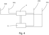
- Figure 4 shows a third cabling architecture for steer-by-wire steering as a second exemplary embodiment of the invention.
- the feedback actuator 4 communicates with the steering actuator 6 on two redundant, private communication channels. If one private communication channel fails, the system can switch to the second private one Use a communication channel that also transmits all the signals needed to operate the steer-by-wire steering.
- the feedback actuator 4 communicates with the motor vehicle via the motor vehicle communication network and transmits the relevant signals from the motor vehicle to the steering actuator 6 and vice versa via the private communication channels.
- two redundant motor vehicle communication channels 500, 501 are provided. If one of the motor vehicle communication channels 500, 501 fails, the other motor vehicle communication channel 501, 500 can completely take over the communication so that the system can continue to work properly.
- the steering actuator 6 does not have a direct communication channel to the motor vehicle. It always communicates with the motor vehicle via the feedback actuator 4.
- a redundant power supply is provided for both the feedback actuator 4 and the steering actuator 6.
- the feedback actuator 4 and the steering actuator 6 are each connected to a first power supply 200 and a second power supply 201. If one of the two power supplies 200, 201 fails, the other, error-free power supply 201, 200 ensures that the feedback actuator 4 and the steering actuator 6 can continue to be operated.
Landscapes
- Engineering & Computer Science (AREA)
- Chemical & Material Sciences (AREA)
- Combustion & Propulsion (AREA)
- Transportation (AREA)
- Mechanical Engineering (AREA)
- Power Steering Mechanism (AREA)
- Steering Control In Accordance With Driving Conditions (AREA)
Description
- Die vorliegende Erfindung betrifft ein Steer-by-Wire-Lenksystem für Kraftfahrzeuge mit den Merkmalen des Oberbegriffs des Anspruchs 1.
- In Steer-by-Wire-Lenksystemen ist die Stellung der gelenkten Räder nicht direkt mit dem Lenkrad gekoppelt. Es besteht eine Verbindung zwischen dem Lenkrad und den gelenkten Rädern über elektrische Signale. An Stelle der mechanischen Kopplung werden ein Lenksteller zur Positionierung der Räder sowie ein Feedback-Aktuator zur Simulation der Rückstellkräfte am Lenkrad verwendet. Um die Sicherheitsanforderungen zu erfüllen, muss das Lenksystem so ausgebildet sein, dass die Funktionalität stets gegeben ist. Hauptsächlich wegen der entstehenden Kosten muss hier ein geeigneter Kompromiss zwischen dem Grad der Fehlertoleranz und der Zahl der redundanten Komponenten gefunden werden.
- Ein Steer-by-wire-Lenksystem nach dem Oberbegriff des Anspruchs 1 ist aus
DE 101 12 514 A1 bekannt. - Aus
DE 100 53 335 A1 ist eine Steer-by-Wire Lenkanlage mit einem Lenkradmodul, einem Steer-by-Wire Steuergerät, einem Versorgungsmodul sowie einem als Lenkmodul bezeichneten Lenksteller bekannt. Das Versorgungsmodul weist mindestens zwei Spannungsquellen auf, so dass auch bei Ausfall einer Spannungsquelle eine sichere Energieversorgung der erfindungsgemäßen Steer-by-Wire Lenkanlage gewährleistet ist. Eine redundante Verbindung von dem Steer-by-Wire-Steuergerät und den anderen Modulen wird über Datenbusse hergestellt. -
US 2004/0026158 A1 beschreibt ein Steer-by-Wire Lenksystem mit einer zentralen Steuereinheit die einen Lenkbefehl eines Fahrers auswertet und in Steuersignal für die Lenksteller umwandelt. Die Elektronik der Lenksteller und die Elektronik der zentralen Steuereinheit sind über zwei Datenübertragungsleitungen eines Lenk-Bussystems verbunden. Die Datenübertragungsleitungen des Lenk-Bussystems sind auch in Verbindung mit zwei voneinander unabhängigen Energiequellen. Die Signale der Lenksensoren, die den Lenkbefehl des Fahrers aufnehmen, werden ebenfalls über die Datenübertragungsleitungen des redundanten Bussystems an die zentrale Steuereinheit übertragen. - In
US 2006/0253726 A1 ist eine fehlertolerante Architektur für ein verteiltes Steuersystem einer Kraftfahrzeuglenkung mit fehlertoleranten Modulen, einem drahtgebundenen Kommunikations-Bus und Funk-Transceivern beschrieben. Die fehlertoleranten Module kommunizieren mittels der Funk-Transceiver, falls die Kommunikation über den drahtgebundenen Bus durch einen Fehler beeinträchtigt ist. Wenn die Funkmodule aktiviert werden, kommunizieren sie über das feldbusbasierte TTP/C-Protokoll. - Es ist Aufgabe der vorliegenden Erfindung, ein Steer-by-Wire-Lenksystem für Kraftfahrzeuge anzugeben, das stets zuverlässig arbeitet, um die Sicherheitsziele zu erfüllen.
- Diese Aufgabe wird von einem Steer-by-Wire-Lenksystem mit den Merkmalen des Anspruchs 1 gelöst. In den Unteransprüchen sind vorteilhafte Weiterbildungen der Erfindung genannt.
- Demnach ist ein Steer-by-Wire-Lenksystem für Kraftfahrzeuge umfassend einen auf die gelenkten Räder wirkenden, in Abhängigkeit eines Fahrerlenkwunsches elektronisch geregelten Lenksteller und einen Rückwirkungen der Straße auf ein Steuer übertragenden Feedback-Aktuator, vorgesehen, wobei der Feedback-Aktuator und der Lenksteller eine redundante Stromversorgung aufweisen. Bei Ausfall einer Stromversorgung kann somit das Lenksystem zuverlässig weiterarbeiten.
- Dabei ist bevorzugt, dass der Feedback-Aktuator und der Lenksteller jeweils mit einer ersten Stromversorgung und einer zweiten Stromversorgung verbunden sind.
- Vorzugsweise sind die beiden Stromversorgungen derart ausgebildet, dass bei einem Ausfall einer der beiden Stromversorgungen die jeweils andere Stromversorgung dafür sorgt, dass der Feedback-Aktuator und der Lenksteller weiter betrieben werden können.
- In einer Ausführungsform sind zusätzlich zwei redundante Kraftfahrzeugkommunikationskanäle vorgesehen, über die der Feedback-Aktuator jeweils sowohl mit dem Kraftfahrzeug als auch mit dem Lenksteller kommuniziert.
- Es sind zwei redundante, private Kommunikationskanäle vorgesehen, über die der Feedback-Aktuator ausschließlich mit dem Lenksteller kommuniziert. Dabei können zwei redundant ausgebildete Kraftfahrzeugkommunikationskanäle vorgesehen sein, über die der Feedback-Aktuator mit dem Kraftfahrzeug kommuniziert, wobei die Kraftfahrzeugkommunikationskanäle und die privaten Kommunikationskanäle dazu ausgebildet sind, dass der Feedback-Aktuator relevante Signale von dem Kraftfahrzeug zu dem Lenksteller und vice versa überträgt.
- Alternativ dazu kann aber auch vorgesehen sein, dass der Lenksteller mit dem Kraftfahrzeug über die zwei redundant ausgebildeten Kraftfahrzeugkommunikationskanäle kommuniziert. In diesem Fall sind die Kraftfahrzeugkommunikationskanäle und die privaten Kommunikationskanäle zwischen dem Feedback-Aktuator und dem Lenksteller dazu ausgebildet, dass der Lenksteller relevante Signale von dem Kraftfahrzeug zu dem Feedback-Aktuator und vice versa überträgt.
- Bevorzugte Ausführungsformen der Erfindung werden nachfolgend anhand der Zeichnungen näher erläutert. Gleichartige oder gleichwirkende Bauteile werden in den Figuren mit denselben Bezugszeichen bezeichnet. Es zeigen:
- Fig. 1:
- eine schematische Darstellung eines Steer-by-Wire-Lenksystems,
- Fig. 2:
- ein Blockdiagramm einer Architektur eines Steer-by-Wire-Lenksystems als Vergleichsbeispiel,
- Fig. 3:
- ein Blockdiagramm einer zweiten Architektur des Steer-by-Wire-Lenksystems als erstes Ausführungsbeispiel der Erfindung, sowie
- Fig. 4:
- ein Blockdiagramm einer dritten Architektur des Steer-by-Wire-Lenksystems als zweites Ausführungsbeispiel der Erfindung.
- In der
Figur 1 ist eine Steer-by-Wire-Lenkung 1 gezeigt. An einer Lenkwelle 2 ist ein nicht dargestellter Drehwinkelsensor angebracht, welcher das durch Drehen des Lenkrads 3 aufgebrachte Fahrerlenkmoment erfasst. Des Weiteren ist an der Lenkwelle 2 ein Feedback-Aktuator 4 angebracht, welcher dazu dient, die Rückwirkungen von der Fahrbahn 70 auf das Lenkrad 3 zu übertragen und somit dem Fahrer eine Rückmeldung über das Lenk- und Fahrverhalten des Fahrzeugs zu geben. Der Fahrerlenkwunsch wird über den vom Drehwinkelsensor gemessenen Drehwinkel der Lenkwelle 2 über Signalleitungen an eine Steuereinheit 5 übertragen. Die Steuereinheit 5 steuert in Abhängigkeit des Signals vom Drehwinkelsensor sowie weiteren Eingangsgrößen, wie z. B. Fahrzeuggeschwindigkeit, Gierrate und dergleichen einen elektrischen Lenksteller 6, auch Lenkungsaktuator genannt, an, welcher die Stellung der gelenkten Räder 7 steuert. Der Lenksteller 6 bewirkt mittels eines Gewindetriebes 8 eine axiale Verlagerung einer Zahnstange. Die gelenkten Räder 7 sind über Spurstangen 9 mit der Zahnstange verbundenen. -
Figur 2 zeigt ein Vergleichsbeispiel einer Verkabelungsarchitektur für ein Steer-by-Wire-Lenksystem. Der Feedback-Aktuator 4 kommuniziert auf zwei Kraftfahrzeugkommunikationskanälen 100, 101 jeweils sowohl mit dem Kraftfahrzeug als auch mit dem Lenksteller 6. Alle benötigten Signale werden auf beiden Fahrzeugkommunikationskanälen 100, 101 zwischen dem Kraftfahrzeug und dem Steer-by-Wire-System 1 und zwischen dem Lenksteller 6 und dem Feedback-Aktuator 4 übertragen. Die beiden Kraftfahrzeugkommunikationskanäle 100, 101 sind redundant ausgebildet. Bei einem Ausfall einer der Kraftfahrzeugkommunikationskanäle 100, 101 kann der andere Kraftfahrzeugkommunikationskanal 101, 100 die Kommunikation vollständig übernehmen, so dass das System ordnungsgemäß weiterarbeiten kann. - Weiterhin ist eine redundante Stromversorgung sowohl für den Feedback-Aktuator 4 als auch für den Lenksteller 6 vorgesehen. Der Feedback-Aktuator 4 und der Lenksteller 6 sind jeweils mit einer ersten Stromversorgung 200 und einer zweiten Stromversorgung 201 verbunden. Bei einem Ausfall einer der beiden Stromversorgungen 200, 201 gewährleistest die andere, fehlerfreie Stromversorgung 201, 200, dass der Feedback-Aktuator 4 und der Lenksteller 6 weiter betrieben werden können.
-
Figur 3 zeigt als erstes Ausführungsbeispiel der Erfindung eine zweite Verkabelungsarchitektur für eine Steer-by-Wire-Lenkung. Der Feedback-Aktuator 4 kommuniziert auf zwei redundanten, privaten Kommunikationskanälen 300, 301 mit dem Lenksteller 6. Bei einem Ausfall eines privaten Kommunikationskanals 300, 301 kann das System auf den zweiten privaten Kommunikationskanal 301, 300 zurückgreifen, der ebenfalls alle Signale überträgt, die für den Betrieb der Steer-by-Wire-Lenkung benötigt werden. Der Lenksteller 6 kommuniziert über das Kraftfahrzeugkommunikationsnetz mit dem Kraftfahrzeug und überträgt die relevanten Signale von dem Kraftfahrzeug zu dem Feedback-Aktuator 4 und vice versa über die privaten Kommunikationskanäle 300, 301. Dazu sind zwei redundant ausgebildete Kraftfahrzeugkommunikationskanäle 400, 401 vorgesehen. Bei einem Ausfall einer der Kraftfahrzeugkommunikationskanäle 400, 401 kann der andere Kraftfahrzeugkommunikationskanal 401, 400 die Kommunikation vollständig übernehmen, so dass das System ordnungsgemäß weiterarbeiten kann. Der Feedback-Aktuator 4 weist dabei keinen unmittelbaren Kommunikationskanal zu dem Kraftfahrzeug auf. Er kommuniziert stets über den Lenksteller 6 mit dem Kraftfahrzeug. Weiterhin ist eine redundante Stromversorgung sowohl für den Feedback-Aktuator 4 als auch für den Lenksteller 6 vorgesehen. Der Feedback-Aktuator 4 und der Lenksteller 6 sind jeweils mit einer ersten Stromversorgung 200 und einer zweiten Stromversorgung 201 verbunden. Bei einem Ausfall einer der beiden Stromversorgungen 200, 201 gewährleistest die andere, fehlerfreie Stromversorgung 201, 200, dass der Feedback-Aktuator 4 und der Lenksteller 6 weiter betrieben werden können. -
Figur 4 zeigt als zweites Ausführungsbeispiel der Erfindung eine dritte Verkabelungsarchitektur für eine Steer-by-Wire-Lenkung. Der Feedback-Aktuator 4 kommuniziert auf zwei redundanten, privaten Kommunikationskanälen mit dem Lenksteller 6. Bei einem Ausfall eines privaten Kommunikationskanals kann das System auf den zweiten privaten Kommunikationskanal zurückgreifen, der ebenfalls alle Signale überträgt, die für den Betrieb der Steer-by-Wire-Lenkung benötigt werden. Der Feedback-Aktuator 4 kommuniziert über das Kraftfahrzeugkommunikationsnetz mit dem Kraftfahrzeug und überträgt die relevanten Signale von dem Kraftfahrzeug zu dem Lenksteller 6 und vice versa über die privaten Kommunikationskanäle. Dazu sind zwei redundant ausgebildete Kraftfahrzeugkommunikationskanäle 500, 501 vorgesehen. Bei einem Ausfall einer der Kraftfahrzeugkommunikationskanäle 500, 501 kann der andere Kraftfahrzeugkommunikationskanal 501, 500 die Kommunikation vollständig übernehmen, so dass das System ordnungsgemäß weiterarbeiten kann. Der Lenksteller 6 weist dabei keinen unmittelbaren Kommunikationskanal zu dem Kraftfahrzeug auf. Er kommuniziert stets über den Feedback-Aktuator 4 mit dem Kraftfahrzeug. - Weiterhin ist eine redundante Stromversorgung sowohl für den Feedback-Aktuator 4 als auch für den Lenksteller 6 vorgesehen. Der Feedback-Aktuator 4 und der Lenksteller 6 sind jeweils mit einer ersten Stromversorgung 200 und einer zweiten Stromversorgung 201 verbunden. Bei einem Ausfall einer der beiden Stromversorgungen 200, 201 gewährleistest die andere, fehlerfreie Stromversorgung 201, 200, dass der Feedback-Aktuator 4 und der Lenksteller 6 weiter betrieben werden können.
Claims (3)
- Steer-by-Wire-Lenksystem (1) für Kraftfahrzeuge aufweisend einen auf die gelenkten Räder (7) wirkenden, in Abhängigkeit eines Fahrerlenkwunsches elektronisch geregelten Lenksteller (6), und einen Rückwirkungen der Straße (70) auf ein Steuer übertragenden Feedback-Aktuator (4), wobei der Feedback-Aktuator (4) und der Lenksteller (6) eine redundante Stromversorgung (200, 201) aufweisen und das Steer-by-Wire-Lenksystem zwei redundante, private Kommunikationskanäle (300, 301) umfasst, über die der Feedback-Aktuator (4) mit dem Lenksteller (6) kommuniziert, dadurch gekennzeichnet, dassdas Steer-by-Wire-Lenksystem zwei redundant ausgebildete Kraftfahrzeugkommunikationskanäle (500, 501) umfasst, über die der Feedback-Aktuator (4) mit dem Kraftfahrzeug kommuniziert, wobei die Kraftfahrzeugkommunikationskanäle (500, 501) und die privaten Kommunikationskanäle dazu ausgebildet sind, dass der Feedback-Aktuator (4) relevante Signale von dem Kraftfahrzeug zu dem Lenksteller (6) und vice versa über die privaten Kommunikationskanäle (300, 301) überträgt oderdas Steer-by-Wire-Lenksystem zwei redundant ausgebildete Kraftfahrzeugkommunikationskanäle (400, 401) umfasst, über die der Lenksteller (6) mit dem Kraftfahrzeug kommuniziert, wobei die Kraftfahrzeugkommunikationskanäle (400, 401) und die privaten Kommunikationskanäle (300, 301) dazu ausgebildet sind, dass der Lenksteller (6) relevante Signale von dem Kraftfahrzeug zu dem Feedback-Aktuator (4) und vice versa über die privaten Kommunikationskanäle (300, 301) überträgt.
- Steer-by-Wire-Lenksystem nach Anspruch 1, dadurch gekennzeichnet, dass der Feedback-Aktuator (4) und der Lenksteller (6) jeweils mit einer ersten Stromversorgung (200) und einer zweiten Stromversorgung (201) verbunden sind.
- Steer-by-Wire-Lenksystem nach Anspruch 2, dadurch gekennzeichnet, dass die beiden Stromversorgungen (200, 201) derart ausgebildet sind, dass bei einem Ausfall einer der beiden Stromversorgungen (200, 201) die jeweils andere Stromversorgung (200, 201) dafür sorgt, dass der Feedback-Aktuator (4) und der Lenksteller (6) weiter betrieben werden können.
Applications Claiming Priority (2)
| Application Number | Priority Date | Filing Date | Title |
|---|---|---|---|
| DE102018106872.7A DE102018106872A1 (de) | 2018-03-22 | 2018-03-22 | Steer-by-Wire Architekturen |
| PCT/EP2019/056366 WO2019179859A1 (de) | 2018-03-22 | 2019-03-14 | Steer-by-wire architekturen |
Publications (2)
| Publication Number | Publication Date |
|---|---|
| EP3768574A1 EP3768574A1 (de) | 2021-01-27 |
| EP3768574B1 true EP3768574B1 (de) | 2023-12-27 |
Family
ID=65894972
Family Applications (1)
| Application Number | Title | Priority Date | Filing Date |
|---|---|---|---|
| EP19712707.9A Active EP3768574B1 (de) | 2018-03-22 | 2019-03-14 | Steer-by-wire architekturen |
Country Status (5)
| Country | Link |
|---|---|
| US (1) | US11702125B2 (de) |
| EP (1) | EP3768574B1 (de) |
| CN (1) | CN111886174A (de) |
| DE (1) | DE102018106872A1 (de) |
| WO (1) | WO2019179859A1 (de) |
Families Citing this family (11)
| Publication number | Priority date | Publication date | Assignee | Title |
|---|---|---|---|---|
| JP7684126B2 (ja) * | 2021-07-21 | 2025-05-27 | 株式会社ジェイテクト | 操舵装置 |
| CN117957161A (zh) * | 2021-09-22 | 2024-04-30 | 蒂森克虏伯普利斯坦股份公司 | 在转向系统发生故障后通过增加反馈扭矩控制机动车的线控转向系统的方法 |
| WO2023046272A1 (en) * | 2021-09-22 | 2023-03-30 | Thyssenkrupp Presta Ag | Steer-by-wire steering system of a road vehicle with external steering wheel angle sensor |
| WO2023046265A1 (en) | 2021-09-22 | 2023-03-30 | Thyssenkrupp Presta Ag | Method to control a steering system of a motor vehicle with increased maximum output power of actuator motor after unilateral failure of the redundant system |
| US20250042464A1 (en) * | 2021-12-10 | 2025-02-06 | Tesla, lnc. | Steer by wire |
| EP4213132B1 (de) * | 2022-01-13 | 2026-03-11 | thyssenkrupp Presta Aktiengesellschaft | Kraftfahrzeug und verfahren zum betrieb eines kraftfahrzeugs |
| KR102668842B1 (ko) * | 2022-06-20 | 2024-05-23 | 에이치엘만도 주식회사 | 조향 장치 |
| DE102023106470A1 (de) | 2023-03-15 | 2024-09-19 | Bayerische Motoren Werke Aktiengesellschaft | Steer-By-Wire-System für ein Kraftfahrzeug sowie Verfahren |
| DE102023109475A1 (de) * | 2023-04-14 | 2024-10-17 | Schaeffler Technologies AG & Co. KG | Aktuatoreinrichtung für ein Steer-by-Wire-System, Steer-by-Wire-System und Verfahren zum Betrieb einer Aktuatoreinrichtung |
| DE102023122853A1 (de) * | 2023-08-25 | 2025-02-27 | Ford Global Technologies, Llc | Lenkradaktuatorvorrichtung für ein Steer-by-Wire-Lenkungssystem eines Kraftfahrzeugs und Betriebsverfahren |
| KR20250060455A (ko) * | 2023-10-26 | 2025-05-07 | 에이치엘만도 주식회사 | 조향 제어 장치 및 방법 |
Citations (1)
| Publication number | Priority date | Publication date | Assignee | Title |
|---|---|---|---|---|
| DE10112514A1 (de) * | 2000-12-22 | 2002-06-27 | Volkswagen Ag | X-by-wire-System für ein Fahrzeug |
Family Cites Families (18)
| Publication number | Priority date | Publication date | Assignee | Title |
|---|---|---|---|---|
| US20040026158A1 (en) | 2000-03-27 | 2004-02-12 | Peter Rieth | Vehicle system and axle guide module for a vehicle steering system |
| DE10042308A1 (de) | 2000-08-29 | 2001-11-15 | Bosch Gmbh Robert | Steer-by-wire-Lenkanlage für ein Fahrzeug mit Servounterstützung der Rückfallebene |
| DE10053335B4 (de) * | 2000-10-27 | 2006-09-07 | Robert Bosch Gmbh | SbW-Lenkanlage für Kraftfahrzeuge |
| DE10135736C1 (de) | 2001-07-21 | 2003-04-03 | Zf Lenksysteme Gmbh | Verfahren zum Ansteuern einer Kupplung einer Steer-by-Wire-Lenkanlage |
| DE10340369B4 (de) * | 2003-09-02 | 2012-01-19 | Zf Lenksysteme Gmbh | Verfahren zur Steuerung mindestens einer mechanischen Stelleinrichtung |
| US20060042858A1 (en) * | 2004-08-24 | 2006-03-02 | Trw Automotive U.S. Llc | Steer-by-wire steering apparatus with redundant electric motor drive systems |
| KR100656328B1 (ko) * | 2004-10-13 | 2006-12-13 | 닛산 지도우샤 가부시키가이샤 | 조향 가능한 차량을 위한 조향 장치 |
| US20060253726A1 (en) * | 2005-05-06 | 2006-11-09 | Vikas Kukshya | Fault-tolerant architecture for a distributed control system |
| JP4839793B2 (ja) | 2005-11-19 | 2011-12-21 | 日産自動車株式会社 | 車両用操舵制御装置 |
| DE102007043005A1 (de) * | 2007-09-06 | 2009-03-12 | Takata-Petri Ag | Lenksystem für ein Kraftfahrzeug mit einem von den gelenkten Rädern des Kraftfahrzeugs entkoppelten oder entkoppelbarem Lenkrad |
| CN101821149A (zh) | 2007-09-06 | 2010-09-01 | 高田-彼得里公开股份有限公司 | 用于机动车辆的方向盘组件 |
| EP2185398B1 (de) | 2007-09-06 | 2012-10-24 | Takata AG | Lenkradbaugruppe für ein kraftfahrzeug |
| CN201405922Y (zh) | 2009-03-13 | 2010-02-17 | 北京工业大学 | 一种汽车线控转向系统 |
| JP5805255B1 (ja) * | 2014-04-07 | 2015-11-04 | 三菱電機株式会社 | 車両用操舵装置 |
| JP6598019B2 (ja) | 2015-04-21 | 2019-10-30 | パナソニックIpマネジメント株式会社 | 運転支援方法およびそれを利用した運転支援装置、運転制御装置、車両、運転支援プログラム |
| DE102017203748A1 (de) | 2017-03-07 | 2018-09-13 | Volkswagen Aktiengesellschaft | Steer by wire-System und Verfahren zum Datenaustausch in einem Steer by wire-System |
| US10442459B2 (en) * | 2017-07-07 | 2019-10-15 | GM Global Technology Operations LLC | Fail operational control of steer-by-wire system without mechanical backup connection |
| DE102018114988A1 (de) | 2018-06-21 | 2019-12-24 | Thyssenkrupp Ag | Steer-by-Wire Architekturen mit zweitem Lenkwinkelsensor |
-
2018
- 2018-03-22 DE DE102018106872.7A patent/DE102018106872A1/de not_active Withdrawn
-
2019
- 2019-03-14 CN CN201980020307.9A patent/CN111886174A/zh active Pending
- 2019-03-14 WO PCT/EP2019/056366 patent/WO2019179859A1/de not_active Ceased
- 2019-03-14 EP EP19712707.9A patent/EP3768574B1/de active Active
- 2019-03-14 US US16/980,007 patent/US11702125B2/en active Active
Patent Citations (1)
| Publication number | Priority date | Publication date | Assignee | Title |
|---|---|---|---|---|
| DE10112514A1 (de) * | 2000-12-22 | 2002-06-27 | Volkswagen Ag | X-by-wire-System für ein Fahrzeug |
Also Published As
| Publication number | Publication date |
|---|---|
| WO2019179859A1 (de) | 2019-09-26 |
| EP3768574A1 (de) | 2021-01-27 |
| DE102018106872A1 (de) | 2019-09-26 |
| US20200406954A1 (en) | 2020-12-31 |
| US11702125B2 (en) | 2023-07-18 |
| CN111886174A (zh) | 2020-11-03 |
Similar Documents
| Publication | Publication Date | Title |
|---|---|---|
| EP3768574B1 (de) | Steer-by-wire architekturen | |
| EP3810487B1 (de) | Steer-by-wire architekturen mit zweitem lenkwinkelsensor | |
| EP3372453B1 (de) | Steer by wire-system und verfahren zum datenaustausch in einem steer by wire-system | |
| DE102018103082B4 (de) | Verfahren zur Bereitstellung einer Lenkkraftunterstützung für ein elektromechanisches Lenksystem eines Kraftfahrzeuges mit einem redundant ausgelegten Steuergerät | |
| DE60221949T2 (de) | Elektrische Lenkung für ein Fahrzeug mit dreifacher Redundanz | |
| DE102018116367A1 (de) | Betriebssichere steuerung des steer-by-wire-systems ohne mechanische backup-verbindung | |
| EP2425304B1 (de) | Steuersystem zum sicheren betreiben von mindestens einer funktionskomponente | |
| EP3765348A1 (de) | Elektromechanische kraftfahrzeuglenkung mit einem redundant ausgelegten steuergerät | |
| WO2021089369A1 (de) | Steer-by-wire-system | |
| DE19834870A1 (de) | Fehlertoleranter elektromechanischer steer-by-wire-Lenksteller | |
| EP4095016B1 (de) | Steer-by-wire-lenksystem | |
| EP3661819B1 (de) | Kontrollsystem für ein kraftfahrzeug, kraftfahrzeug, verfahren zur kontrolle eines kraftfahrzeugs, computerprogrammprodukt und computerlesbares medium | |
| DE112016001615T5 (de) | Servolenkungsvorrichtung und Steuergerät für Vorrichtung im Fahrzeug | |
| EP1989470B1 (de) | Sicherheitskonzept für eine getriebestellvorrichtung | |
| EP1972514A1 (de) | Kraftahrzeug mit einem X-by-wire-System und Verfahren zum Betreiben eines X-by-wire-Systems eines Kraftfahrzeugs | |
| DE102017202398A1 (de) | Mikrocontroller und elektronische steuereinheit | |
| EP3470301B1 (de) | Lenkungssteuersystem für ein lenksystem eines kraftfahrzeuges sowie verfahren zum betreiben eines lenkungssteuersystems | |
| DE102022205354A1 (de) | Steer-by-Wire-Lenksystem | |
| DE112021008257T5 (de) | Steer-by-Wire-Lenksystem eines Straßenfahrzeugs mit externem Lenkradwinkelsensor | |
| EP4048574B1 (de) | Auswertevorrichtung zur fehlertoleranten auswertung von sensorsignalen für ein motorsteuergerät einer kraftfahrzeuglenkung und kraftfahrzeuglenkung | |
| EP4230503A1 (de) | Steer-by-wire-lenksystem, steuergerät und verfahren zum betreiben eines steer-by-wire-lenksystems | |
| EP3984863B1 (de) | Lenkungssteuerungssystem eines mehrgliedrigen fahrzeugs | |
| DE10344070B4 (de) | Antriebsmodul für eine Druckmaschine | |
| DE102018200998A1 (de) | Steer-by-Wire-Lenkvorrichtung | |
| WO2017042010A1 (de) | Vorrichtung zum betreiben eines servolenksystems, servolenksystem |
Legal Events
| Date | Code | Title | Description |
|---|---|---|---|
| STAA | Information on the status of an ep patent application or granted ep patent |
Free format text: STATUS: UNKNOWN |
|
| STAA | Information on the status of an ep patent application or granted ep patent |
Free format text: STATUS: THE INTERNATIONAL PUBLICATION HAS BEEN MADE |
|
| PUAI | Public reference made under article 153(3) epc to a published international application that has entered the european phase |
Free format text: ORIGINAL CODE: 0009012 |
|
| STAA | Information on the status of an ep patent application or granted ep patent |
Free format text: STATUS: REQUEST FOR EXAMINATION WAS MADE |
|
| 17P | Request for examination filed |
Effective date: 20201022 |
|
| AK | Designated contracting states |
Kind code of ref document: A1 Designated state(s): AL AT BE BG CH CY CZ DE DK EE ES FI FR GB GR HR HU IE IS IT LI LT LU LV MC MK MT NL NO PL PT RO RS SE SI SK SM TR |
|
| AX | Request for extension of the european patent |
Extension state: BA ME |
|
| RAP1 | Party data changed (applicant data changed or rights of an application transferred) |
Owner name: THYSSENKRUPP PRESTA AG Owner name: THYSSENKRUPP AG |
|
| RAP1 | Party data changed (applicant data changed or rights of an application transferred) |
Owner name: THYSSENKRUPP AG Owner name: THYSSENKRUPP PRESTA AG |
|
| DAV | Request for validation of the european patent (deleted) | ||
| DAX | Request for extension of the european patent (deleted) | ||
| STAA | Information on the status of an ep patent application or granted ep patent |
Free format text: STATUS: EXAMINATION IS IN PROGRESS |
|
| 17Q | First examination report despatched |
Effective date: 20221124 |
|
| GRAP | Despatch of communication of intention to grant a patent |
Free format text: ORIGINAL CODE: EPIDOSNIGR1 |
|
| STAA | Information on the status of an ep patent application or granted ep patent |
Free format text: STATUS: GRANT OF PATENT IS INTENDED |
|
| INTG | Intention to grant announced |
Effective date: 20230913 |
|
| GRAS | Grant fee paid |
Free format text: ORIGINAL CODE: EPIDOSNIGR3 |
|
| GRAA | (expected) grant |
Free format text: ORIGINAL CODE: 0009210 |
|
| STAA | Information on the status of an ep patent application or granted ep patent |
Free format text: STATUS: THE PATENT HAS BEEN GRANTED |
|
| AK | Designated contracting states |
Kind code of ref document: B1 Designated state(s): AL AT BE BG CH CY CZ DE DK EE ES FI FR GB GR HR HU IE IS IT LI LT LU LV MC MK MT NL NO PL PT RO RS SE SI SK SM TR |
|
| REG | Reference to a national code |
Ref country code: GB Ref legal event code: FG4D Free format text: NOT ENGLISH |
|
| REG | Reference to a national code |
Ref country code: CH Ref legal event code: EP |
|
| REG | Reference to a national code |
Ref country code: DE Ref legal event code: R096 Ref document number: 502019010225 Country of ref document: DE |
|
| REG | Reference to a national code |
Ref country code: IE Ref legal event code: FG4D Free format text: LANGUAGE OF EP DOCUMENT: GERMAN |
|
| REG | Reference to a national code |
Ref country code: DE Ref legal event code: R084 Ref document number: 502019010225 Country of ref document: DE |
|
| PG25 | Lapsed in a contracting state [announced via postgrant information from national office to epo] |
Ref country code: GR Free format text: LAPSE BECAUSE OF FAILURE TO SUBMIT A TRANSLATION OF THE DESCRIPTION OR TO PAY THE FEE WITHIN THE PRESCRIBED TIME-LIMIT Effective date: 20240328 |
|
| REG | Reference to a national code |
Ref country code: LT Ref legal event code: MG9D |
|
| PG25 | Lapsed in a contracting state [announced via postgrant information from national office to epo] |
Ref country code: LT Free format text: LAPSE BECAUSE OF FAILURE TO SUBMIT A TRANSLATION OF THE DESCRIPTION OR TO PAY THE FEE WITHIN THE PRESCRIBED TIME-LIMIT Effective date: 20231227 |
|
| PG25 | Lapsed in a contracting state [announced via postgrant information from national office to epo] |
Ref country code: ES Free format text: LAPSE BECAUSE OF FAILURE TO SUBMIT A TRANSLATION OF THE DESCRIPTION OR TO PAY THE FEE WITHIN THE PRESCRIBED TIME-LIMIT Effective date: 20231227 |
|
| PG25 | Lapsed in a contracting state [announced via postgrant information from national office to epo] |
Ref country code: LT Free format text: LAPSE BECAUSE OF FAILURE TO SUBMIT A TRANSLATION OF THE DESCRIPTION OR TO PAY THE FEE WITHIN THE PRESCRIBED TIME-LIMIT Effective date: 20231227 Ref country code: GR Free format text: LAPSE BECAUSE OF FAILURE TO SUBMIT A TRANSLATION OF THE DESCRIPTION OR TO PAY THE FEE WITHIN THE PRESCRIBED TIME-LIMIT Effective date: 20240328 Ref country code: FI Free format text: LAPSE BECAUSE OF FAILURE TO SUBMIT A TRANSLATION OF THE DESCRIPTION OR TO PAY THE FEE WITHIN THE PRESCRIBED TIME-LIMIT Effective date: 20231227 Ref country code: ES Free format text: LAPSE BECAUSE OF FAILURE TO SUBMIT A TRANSLATION OF THE DESCRIPTION OR TO PAY THE FEE WITHIN THE PRESCRIBED TIME-LIMIT Effective date: 20231227 Ref country code: BG Free format text: LAPSE BECAUSE OF FAILURE TO SUBMIT A TRANSLATION OF THE DESCRIPTION OR TO PAY THE FEE WITHIN THE PRESCRIBED TIME-LIMIT Effective date: 20240327 |
|
| REG | Reference to a national code |
Ref country code: NL Ref legal event code: MP Effective date: 20231227 |
|
| PG25 | Lapsed in a contracting state [announced via postgrant information from national office to epo] |
Ref country code: NL Free format text: LAPSE BECAUSE OF FAILURE TO SUBMIT A TRANSLATION OF THE DESCRIPTION OR TO PAY THE FEE WITHIN THE PRESCRIBED TIME-LIMIT Effective date: 20231227 |
|
| PG25 | Lapsed in a contracting state [announced via postgrant information from national office to epo] |
Ref country code: SE Free format text: LAPSE BECAUSE OF FAILURE TO SUBMIT A TRANSLATION OF THE DESCRIPTION OR TO PAY THE FEE WITHIN THE PRESCRIBED TIME-LIMIT Effective date: 20231227 Ref country code: RS Free format text: LAPSE BECAUSE OF FAILURE TO SUBMIT A TRANSLATION OF THE DESCRIPTION OR TO PAY THE FEE WITHIN THE PRESCRIBED TIME-LIMIT Effective date: 20231227 Ref country code: NO Free format text: LAPSE BECAUSE OF FAILURE TO SUBMIT A TRANSLATION OF THE DESCRIPTION OR TO PAY THE FEE WITHIN THE PRESCRIBED TIME-LIMIT Effective date: 20240327 Ref country code: NL Free format text: LAPSE BECAUSE OF FAILURE TO SUBMIT A TRANSLATION OF THE DESCRIPTION OR TO PAY THE FEE WITHIN THE PRESCRIBED TIME-LIMIT Effective date: 20231227 Ref country code: LV Free format text: LAPSE BECAUSE OF FAILURE TO SUBMIT A TRANSLATION OF THE DESCRIPTION OR TO PAY THE FEE WITHIN THE PRESCRIBED TIME-LIMIT Effective date: 20231227 Ref country code: HR Free format text: LAPSE BECAUSE OF FAILURE TO SUBMIT A TRANSLATION OF THE DESCRIPTION OR TO PAY THE FEE WITHIN THE PRESCRIBED TIME-LIMIT Effective date: 20231227 |
|
| PG25 | Lapsed in a contracting state [announced via postgrant information from national office to epo] |
Ref country code: IS Free format text: LAPSE BECAUSE OF FAILURE TO SUBMIT A TRANSLATION OF THE DESCRIPTION OR TO PAY THE FEE WITHIN THE PRESCRIBED TIME-LIMIT Effective date: 20240427 |
|
| PG25 | Lapsed in a contracting state [announced via postgrant information from national office to epo] |
Ref country code: CZ Free format text: LAPSE BECAUSE OF FAILURE TO SUBMIT A TRANSLATION OF THE DESCRIPTION OR TO PAY THE FEE WITHIN THE PRESCRIBED TIME-LIMIT Effective date: 20231227 |
|
| PG25 | Lapsed in a contracting state [announced via postgrant information from national office to epo] |
Ref country code: SK Free format text: LAPSE BECAUSE OF FAILURE TO SUBMIT A TRANSLATION OF THE DESCRIPTION OR TO PAY THE FEE WITHIN THE PRESCRIBED TIME-LIMIT Effective date: 20231227 |
|
| PG25 | Lapsed in a contracting state [announced via postgrant information from national office to epo] |
Ref country code: SM Free format text: LAPSE BECAUSE OF FAILURE TO SUBMIT A TRANSLATION OF THE DESCRIPTION OR TO PAY THE FEE WITHIN THE PRESCRIBED TIME-LIMIT Effective date: 20231227 Ref country code: SK Free format text: LAPSE BECAUSE OF FAILURE TO SUBMIT A TRANSLATION OF THE DESCRIPTION OR TO PAY THE FEE WITHIN THE PRESCRIBED TIME-LIMIT Effective date: 20231227 Ref country code: RO Free format text: LAPSE BECAUSE OF FAILURE TO SUBMIT A TRANSLATION OF THE DESCRIPTION OR TO PAY THE FEE WITHIN THE PRESCRIBED TIME-LIMIT Effective date: 20231227 Ref country code: IT Free format text: LAPSE BECAUSE OF FAILURE TO SUBMIT A TRANSLATION OF THE DESCRIPTION OR TO PAY THE FEE WITHIN THE PRESCRIBED TIME-LIMIT Effective date: 20231227 Ref country code: IS Free format text: LAPSE BECAUSE OF FAILURE TO SUBMIT A TRANSLATION OF THE DESCRIPTION OR TO PAY THE FEE WITHIN THE PRESCRIBED TIME-LIMIT Effective date: 20240427 Ref country code: EE Free format text: LAPSE BECAUSE OF FAILURE TO SUBMIT A TRANSLATION OF THE DESCRIPTION OR TO PAY THE FEE WITHIN THE PRESCRIBED TIME-LIMIT Effective date: 20231227 Ref country code: CZ Free format text: LAPSE BECAUSE OF FAILURE TO SUBMIT A TRANSLATION OF THE DESCRIPTION OR TO PAY THE FEE WITHIN THE PRESCRIBED TIME-LIMIT Effective date: 20231227 |
|
| PG25 | Lapsed in a contracting state [announced via postgrant information from national office to epo] |
Ref country code: PL Free format text: LAPSE BECAUSE OF FAILURE TO SUBMIT A TRANSLATION OF THE DESCRIPTION OR TO PAY THE FEE WITHIN THE PRESCRIBED TIME-LIMIT Effective date: 20231227 Ref country code: PT Free format text: LAPSE BECAUSE OF FAILURE TO SUBMIT A TRANSLATION OF THE DESCRIPTION OR TO PAY THE FEE WITHIN THE PRESCRIBED TIME-LIMIT Effective date: 20240429 |
|
| PG25 | Lapsed in a contracting state [announced via postgrant information from national office to epo] |
Ref country code: PT Free format text: LAPSE BECAUSE OF FAILURE TO SUBMIT A TRANSLATION OF THE DESCRIPTION OR TO PAY THE FEE WITHIN THE PRESCRIBED TIME-LIMIT Effective date: 20240429 Ref country code: PL Free format text: LAPSE BECAUSE OF FAILURE TO SUBMIT A TRANSLATION OF THE DESCRIPTION OR TO PAY THE FEE WITHIN THE PRESCRIBED TIME-LIMIT Effective date: 20231227 |
|
| REG | Reference to a national code |
Ref country code: DE Ref legal event code: R097 Ref document number: 502019010225 Country of ref document: DE |
|
| PG25 | Lapsed in a contracting state [announced via postgrant information from national office to epo] |
Ref country code: DK Free format text: LAPSE BECAUSE OF FAILURE TO SUBMIT A TRANSLATION OF THE DESCRIPTION OR TO PAY THE FEE WITHIN THE PRESCRIBED TIME-LIMIT Effective date: 20231227 |
|
| PG25 | Lapsed in a contracting state [announced via postgrant information from national office to epo] |
Ref country code: DK Free format text: LAPSE BECAUSE OF FAILURE TO SUBMIT A TRANSLATION OF THE DESCRIPTION OR TO PAY THE FEE WITHIN THE PRESCRIBED TIME-LIMIT Effective date: 20231227 |
|
| REG | Reference to a national code |
Ref country code: CH Ref legal event code: PL |
|
| PLBE | No opposition filed within time limit |
Free format text: ORIGINAL CODE: 0009261 |
|
| STAA | Information on the status of an ep patent application or granted ep patent |
Free format text: STATUS: NO OPPOSITION FILED WITHIN TIME LIMIT |
|
| PG25 | Lapsed in a contracting state [announced via postgrant information from national office to epo] |
Ref country code: LU Free format text: LAPSE BECAUSE OF NON-PAYMENT OF DUE FEES Effective date: 20240314 |
|
| PG25 | Lapsed in a contracting state [announced via postgrant information from national office to epo] |
Ref country code: MC Free format text: LAPSE BECAUSE OF FAILURE TO SUBMIT A TRANSLATION OF THE DESCRIPTION OR TO PAY THE FEE WITHIN THE PRESCRIBED TIME-LIMIT Effective date: 20231227 |
|
| GBPC | Gb: european patent ceased through non-payment of renewal fee |
Effective date: 20240327 |
|
| PG25 | Lapsed in a contracting state [announced via postgrant information from national office to epo] |
Ref country code: MC Free format text: LAPSE BECAUSE OF FAILURE TO SUBMIT A TRANSLATION OF THE DESCRIPTION OR TO PAY THE FEE WITHIN THE PRESCRIBED TIME-LIMIT Effective date: 20231227 Ref country code: LU Free format text: LAPSE BECAUSE OF NON-PAYMENT OF DUE FEES Effective date: 20240314 |
|
| 26N | No opposition filed |
Effective date: 20240930 |
|
| REG | Reference to a national code |
Ref country code: BE Ref legal event code: MM Effective date: 20240331 |
|
| PG25 | Lapsed in a contracting state [announced via postgrant information from national office to epo] |
Ref country code: BE Free format text: LAPSE BECAUSE OF NON-PAYMENT OF DUE FEES Effective date: 20240331 |
|
| PG25 | Lapsed in a contracting state [announced via postgrant information from national office to epo] |
Ref country code: GB Free format text: LAPSE BECAUSE OF NON-PAYMENT OF DUE FEES Effective date: 20240327 |
|
| PG25 | Lapsed in a contracting state [announced via postgrant information from national office to epo] |
Ref country code: FR Free format text: LAPSE BECAUSE OF NON-PAYMENT OF DUE FEES Effective date: 20240331 |
|
| PG25 | Lapsed in a contracting state [announced via postgrant information from national office to epo] |
Ref country code: IE Free format text: LAPSE BECAUSE OF NON-PAYMENT OF DUE FEES Effective date: 20240314 |
|
| PG25 | Lapsed in a contracting state [announced via postgrant information from national office to epo] |
Ref country code: IE Free format text: LAPSE BECAUSE OF NON-PAYMENT OF DUE FEES Effective date: 20240314 Ref country code: GB Free format text: LAPSE BECAUSE OF NON-PAYMENT OF DUE FEES Effective date: 20240327 Ref country code: FR Free format text: LAPSE BECAUSE OF NON-PAYMENT OF DUE FEES Effective date: 20240331 Ref country code: BE Free format text: LAPSE BECAUSE OF NON-PAYMENT OF DUE FEES Effective date: 20240331 Ref country code: CH Free format text: LAPSE BECAUSE OF NON-PAYMENT OF DUE FEES Effective date: 20240331 |
|
| PG25 | Lapsed in a contracting state [announced via postgrant information from national office to epo] |
Ref country code: SI Free format text: LAPSE BECAUSE OF FAILURE TO SUBMIT A TRANSLATION OF THE DESCRIPTION OR TO PAY THE FEE WITHIN THE PRESCRIBED TIME-LIMIT Effective date: 20231227 |
|
| REG | Reference to a national code |
Ref country code: AT Ref legal event code: MM01 Ref document number: 1644277 Country of ref document: AT Kind code of ref document: T Effective date: 20240314 |
|
| PG25 | Lapsed in a contracting state [announced via postgrant information from national office to epo] |
Ref country code: AT Free format text: LAPSE BECAUSE OF NON-PAYMENT OF DUE FEES Effective date: 20240314 |
|
| PG25 | Lapsed in a contracting state [announced via postgrant information from national office to epo] |
Ref country code: CY Free format text: LAPSE BECAUSE OF FAILURE TO SUBMIT A TRANSLATION OF THE DESCRIPTION OR TO PAY THE FEE WITHIN THE PRESCRIBED TIME-LIMIT; INVALID AB INITIO Effective date: 20190314 |
|
| PG25 | Lapsed in a contracting state [announced via postgrant information from national office to epo] |
Ref country code: HU Free format text: LAPSE BECAUSE OF FAILURE TO SUBMIT A TRANSLATION OF THE DESCRIPTION OR TO PAY THE FEE WITHIN THE PRESCRIBED TIME-LIMIT; INVALID AB INITIO Effective date: 20190314 |
|
| PG25 | Lapsed in a contracting state [announced via postgrant information from national office to epo] |
Ref country code: TR Free format text: LAPSE BECAUSE OF FAILURE TO SUBMIT A TRANSLATION OF THE DESCRIPTION OR TO PAY THE FEE WITHIN THE PRESCRIBED TIME-LIMIT Effective date: 20231227 |
|
| PGFP | Annual fee paid to national office [announced via postgrant information from national office to epo] |
Ref country code: DE Payment date: 20260319 Year of fee payment: 8 |