EP3768603B1 - Ausgabesystem - Google Patents
Ausgabesystem Download PDFInfo
- Publication number
- EP3768603B1 EP3768603B1 EP19771819.0A EP19771819A EP3768603B1 EP 3768603 B1 EP3768603 B1 EP 3768603B1 EP 19771819 A EP19771819 A EP 19771819A EP 3768603 B1 EP3768603 B1 EP 3768603B1
- Authority
- EP
- European Patent Office
- Prior art keywords
- lid
- dispensing system
- post
- dispensing
- bottom end
- Prior art date
- Legal status (The legal status is an assumption and is not a legal conclusion. Google has not performed a legal analysis and makes no representation as to the accuracy of the status listed.)
- Active
Links
Images


Classifications
-
- B—PERFORMING OPERATIONS; TRANSPORTING
- B65—CONVEYING; PACKING; STORING; HANDLING THIN OR FILAMENTARY MATERIAL
- B65D—CONTAINERS FOR STORAGE OR TRANSPORT OF ARTICLES OR MATERIALS, e.g. BAGS, BARRELS, BOTTLES, BOXES, CANS, CARTONS, CRATES, DRUMS, JARS, TANKS, HOPPERS, FORWARDING CONTAINERS; ACCESSORIES, CLOSURES, OR FITTINGS THEREFOR; PACKAGING ELEMENTS; PACKAGES
- B65D17/00—Rigid or semi-rigid containers specially constructed to be opened by cutting or piercing, or by tearing of frangible members or portions
- B65D17/42—Rigid or semi-rigid containers specially constructed to be opened by cutting or piercing, or by tearing of frangible members or portions with cutting, punching, or cutter accommodating means
- B65D17/44—Rigid or semi-rigid containers specially constructed to be opened by cutting or piercing, or by tearing of frangible members or portions with cutting, punching, or cutter accommodating means in which the puncturing tool serves as closure
-
- B—PERFORMING OPERATIONS; TRANSPORTING
- B65—CONVEYING; PACKING; STORING; HANDLING THIN OR FILAMENTARY MATERIAL
- B65D—CONTAINERS FOR STORAGE OR TRANSPORT OF ARTICLES OR MATERIALS, e.g. BAGS, BARRELS, BOTTLES, BOXES, CANS, CARTONS, CRATES, DRUMS, JARS, TANKS, HOPPERS, FORWARDING CONTAINERS; ACCESSORIES, CLOSURES, OR FITTINGS THEREFOR; PACKAGING ELEMENTS; PACKAGES
- B65D81/00—Containers, packaging elements, or packages, for contents presenting particular transport or storage problems, or adapted to be used for non-packaging purposes after removal of contents
- B65D81/32—Containers, packaging elements, or packages, for contents presenting particular transport or storage problems, or adapted to be used for non-packaging purposes after removal of contents for packaging two or more different materials which must be maintained separate prior to use in admixture
- B65D81/3205—Separate rigid or semi-rigid containers joined to each other at their external surfaces
- B65D81/3211—Separate rigid or semi-rigid containers joined to each other at their external surfaces coaxially and provided with means facilitating admixture
-
- B—PERFORMING OPERATIONS; TRANSPORTING
- B65—CONVEYING; PACKING; STORING; HANDLING THIN OR FILAMENTARY MATERIAL
- B65D—CONTAINERS FOR STORAGE OR TRANSPORT OF ARTICLES OR MATERIALS, e.g. BAGS, BARRELS, BOTTLES, BOXES, CANS, CARTONS, CRATES, DRUMS, JARS, TANKS, HOPPERS, FORWARDING CONTAINERS; ACCESSORIES, CLOSURES, OR FITTINGS THEREFOR; PACKAGING ELEMENTS; PACKAGES
- B65D17/00—Rigid or semi-rigid containers specially constructed to be opened by cutting or piercing, or by tearing of frangible members or portions
- B65D17/42—Rigid or semi-rigid containers specially constructed to be opened by cutting or piercing, or by tearing of frangible members or portions with cutting, punching, or cutter accommodating means
Definitions
- the present invention relates generally to a dispensing system for dispensing a substance into a container of another substance or onto some other target region.
- a container may be a bottle, flexible pouch, machine, vessel, etc., having an interior accessible through an opening in the container.
- a typical closure may be a cap, cover, or lid arranged at an opening to the container interior and is cooperatively received by a receiving structure on the container.
- a receiving structure may include mating threads, snap-fit beads or grooves, toggle clamps, friction fittings, or other such features.
- Various materials or substances may be stored in the system, such as medicaments, additives, oils, lotions, creams, gels, liquids, food items, granules, powders, etc.
- the container with the closure mounted thereon, and the contents stored therein, may be characterized as a "package.”
- Some substances such as powders or liquids benefit from being stored in a concentrated form until mixed with another substance (e.g., water or another liquid or other material) in the container just prior to use or consumption.
- another substance e.g., water or another liquid or other material
- Current powders or liquids may be stored in a package that cannot easily be opened by a user and combined with another substance stored in a container in a clean manner.
- current powders or additives may be stored in a package that cannot easily be used with a wide variety of containers having different sized container openings.
- the inventors of the present invention have determined that it would be desirable to provide a single dose dispensing system for substances that may be used with a variety of containers having differently sized container openings.
- the inventors of the present invention have further found that it would be beneficial to provide a dispensing system that would be easily and ergonomically actuated by a user.
- the inventors of the present invention have also determined that, in many applications, it may be desirable to provide an improved dispensing system that minimizes the likelihood of inadvertent opening of the dispensing system during shipping or handling wherein the improved dispensing system eliminates the need for any additional protective packaging, such as a larger box or carton, or the inclusion of dampening structures or inserts that would otherwise be included to minimize the likelihood of the inadvertent actuation of the dispensing system.
- the inventors of the present invention have also determined that it would be desirable to provide an improved dispensing system that (1) minimizes the likelihood of inadvertent actuation of the dispensing system during shipping or handling, and (2) would actuate only when engaged by a user applying a specific, yet simple, action.
- the inventors of the present invention have determined that, in many applications, it may be desirable to provide an improved dispensing system that minimizes the potential for accumulation of residue, spilled contents, etc. during the use of the system to dispense a stored substance into a container.
- the inventors of the present invention have determined that it would be beneficial in many applications to provide an improved dispensing system that can include or exhibit one or more of the following additional features or capabilities: (1) substantially universal compatibility with many types of sizes of containers (especially water bottles) without the need for the consumer to recognize and select a container having a particular neck size; and (2) a small format and size that permits the user to easily carry only the dispensing system on his or her person to another location where the user can then procure a container with which to use the dispensing system at the user's choice of location.
- the inventors of the present invention have determined that it can be beneficial for a supplier of an additive to sell and ship a separate, smaller concentrated additive dispensing package without a larger container that would be required for a pre-mixed product containing the additive already combined with another substance (e.g., water). This could provide savings in transportation costs and could advantageously allow the user or consumer to decide when, where, and into what other product to dispense the additive.
- another substance e.g., water
- the inventors of the present invention have determined that it can be desirable in some applications to provide such an improved dispensing system that accommodates dispensing a substance directly onto a target area or region, such as onto food on a plate or held in the hand, as well as, or instead of, into another substance stored in the interior of a container.
- the inventors of the present invention have also determined that it would be desirable to provide an improved dispensing system that can be configured for use with dispensing a stored substance into a container of a fluent substance so as to have one or more of the following advantages: (1) an improved ease of manufacture and/or assembly, and (ii) a reduced cost of manufacture and/or assembly.
- the inventors of the present invention have invented a novel structure for a dispensing system for use with dispensing a stored substance into a container, or onto some other target region, wherein the system includes various advantageous features not heretofore taught or contemplated by the prior art.
- US 4,634,003 A discloses a container according to the preamble of claim 1 for separately accommodating a pair of liquids, such as mineral water and whisky, including a main body for accommodating a first liquid, a small cup for accommodating a second liquid, provided with a flange extending from the entire periphery of an upper end of the small cup and a skirt extending downward from the entire periphery of an upper end of the flange, and a flexible lid for liquid-tightly sealing an upper free opening of the small cup.
- the small cup is fit into an upper free opening of the main body engaging the flange and the skirt with the entire periphery of an upper end of the main body.
- the small cup has a specified area, in a bottom wall, at least partially bordered by a score line.
- the lid has a downward projection. The specified area is broken by pushing down the lid until a tip of the projection presses to break the specified area, whereby the second liquid flows down into the main body and mixes with the first liquid in the main body.
- a dispensing system for use in dispensing a substance that may be stored within the system.
- the system includes a body having an outer wall with an exterior surface and having an interior surface defining a volume for storing a substance.
- the outer wall has an open top end and a sealed bottom end.
- the exterior surface of the outer wall defines at least one annular shoulder to accommodate supporting the body on a container having a predetermined opening size.
- the exterior surface of the outer wall defines a plurality of annular shoulders that increase in size from the sealed bottom end to the top end of the outer wall.
- the system includes a flexible lid that is connected to the body to cover the open top end. The lid has a press portion for being engaged by a user of the system.
- the lid has a first position and a second position moved relative to the first position, wherein in the second position at least a portion of the lid is deflected toward the sealed bottom end of the body.
- the system further includes a post connected to the lid. The post is configured in the second position of the lid to breach the sealed bottom end of the body to form a dispensing orifice to accommodate movement of a substance out of the body.
- the post is formed unitarily with the lid.
- the lid includes at least one raised annular portion and at least one recessed annular portion surrounding the press portion.
- the sealed bottom end of the body includes a frangible portion of the body that is breached by movement of the post into the second position of the lid to create the dispensing orifice.
- the sealed bottom end of the body includes a bottom aperture in the body and further includes a bottom liner that is sealed over the bottom aperture.
- the plurality of annular shoulder are spaced vertically.
- the dispensing system further includes a ring-shaped foil liner sealed between the lid and the body.
- the lid is inherently biased to its first position.
- the dispensing system is provided in combination with a fluent substance, the system and the fluent substance together defining a package.
- the sealed bottom end includes a pair of intersecting lines of reduced thickness material and four petals defined between the intersecting lines.
- the dispensing system is provided in combination with a pod containing a fluent substance, whereby the system, the pod, and the fluent substance together define a package.
- FIG. 10 For ease of description, many figures illustrating the invention show embodiments of a dispensing system in the typical orientation that the system would have when located at the opening of a container such as an upright bottle, and terms such as “inward”, “outward”, “upper”, “lower”, “axial”, “radial”, “lateral”, etc., are used with reference to this orientation.
- the term “axially inward” is to be understood as in the direction along a central axis 30 (visible in Fig. 1 ) of the system, toward the interior of the container ( Fig. 10 ).
- the term “axially outward” is to be understood as in the direction along a central axis 30, away from the interior of the container ( Fig. 10 ).
- radially inward is to be understood as in the radial direction toward the central axis 30.
- radially outward is to be understood as in the radial direction away from the central axis 30.
- laterally inward is to be understood as in a direction toward the central axis 30, in a plane normal to the central axis 30.
- laterally outward is to be understood as in a direction away from the central axis 30, in a plane normal to the central axis 30. It will be understood, however, that the system of this invention may be manufactured, stored, transported, used, and sold in an orientation other than the specific orientation described and illustrated.
- dispensing systems of this invention are especially suitable for use with a variety of conventional or special containers, the details of which, although not fully illustrated or described, would be apparent to those having skill in the art and an understanding of such containers.
- the particular container illustrated is not intended to limit the present invention. It will also be understood by those of ordinary skill that novel and non-obvious inventive aspects are embodied in the described systems alone.
- the dispensing systems described herein are especially suitable for use in dispensing a fluent substance as an additive into a container that contains a liquid such as water.
- a fluent substance may be, for example, food additives, a personal care product, an industrial product, a household product, or other types of products.
- Such substances may be for internal or external use by humans or animals, or for other uses (e.g., activities involving medicine, commercial or household maintenance, agriculture, manufacturing, etc.).
- FIG. 1-14 A first embodiment of an alternative dispensing system not part of the present invention is illustrated in Figs. 1-14 , wherein the system is designated generally by the reference number 40.
- the first illustrated embodiment of the system 40 has the form of a self-contained article or package that is configured to be (i) selectively placed at an opening of a container 44 ( Fig. 8 ) and (ii) actuated to dispense a fluent substance such as a concentrated powder into the container 44.
- the container 44 illustrated in Figs. 8-11 has the form of a bottle that would typically contain another fluent substance (e.g., water).
- the fluent substance to be dispensed from the system 40 is not illustrated in the figures because the substance may take a variety of forms.
- cap 8-11 is typically provided initially with a cap or other closure (not illustrated) that can be removably mounted to the container with threads for mating with threads 45 on the container 44.
- the closure is first removed by the user prior to the user placing the system 40 on the opening of the container 44.
- Closure mounting features other than mating threads could be used, such as snap-fit beads and grooves, toggle clamps, friction fittings, etc.
- the container may be any conventional type, such as a collapsible, flexible pouch, or may be a generally rigid bottle that has somewhat flexible, resilient walls.
- the system 40 may be used to dispense a substance outside of, or apart from, a container-such as directly onto a target area (e.g., a hand held item of food or other material).
- the container may be made from a material suitable for the intended application.
- the container may be a pouch made from a thin, flexible material (wherein such a material could be a polyethylene terephthalate (PET) film or a polyethylene film and/or an aluminum foil).
- PET polyethylene terephthalate
- a more rigid container e.g., a bottle
- a thicker, less flexible material such as molded polyethylene, polypropylene, polyethylene terephthalate, polyvinylchloride, glass, metal, or other materials.
- the manufacturer will then ship the unassembled components of the dispensing system 40 to a filler facility at another location where the system 40 would be filled with a product and sealed in the form of a package that would be encountered by a customer or user of the system 40.
- the first illustrated embodiment of the dispensing system 40 includes the following basic components: a base or body 54; and a flexible lid 56 that is mounted atop the body 54, wherein the lid 56 includes a post 58 extending into the hollow interior of the body 54.
- the body 54 defines a volume for storing a fluent substance to be dispensed.
- the lid 56 is flexible (e.g., resiliently deflectable or in some alternative embodiments permanently deformable), whereby the lid 56 has an unactuated, first position ( Fig.
- the lid 56 may be pressed by a finger or thumb of a user of the dispensing system 40 to move the lid 56 into an actuated, second position ( Fig. 11 ). Movement of the lid 56 axially inwardly or downwardly into its second position causes the post 58 to breach a bottom portion or bottom seal on the body 54 to form a dispensing orifice to permit the dispensing of the stored substance from the system 40.
- the dispensing orifice created by the movement of the post 58 may be located at the opening of a container 44 or a target area so that the user can dispense the substance stored within the system 40 to the container 44 or target area.
- the body 54, lid 56, and post 58 are preferably formed or molded from a suitable thermoplastic material such as polypropylene or polyethylene. Other materials may be employed instead. It will be understood that in alternative designs (not illustrated), one or more of the basic components or sub-components may be separately or sequentially formed or molded (such as through bi-injection molding). Alternatively, the basic components may be molded initially as one connected, unitary structure, and then broken apart, and then re-assembled into an operative combination or assembly.
- the lid 56 is connected to the body 54 of the system 40 by a ring-like foil or composite liner 62 which can be permanently sealed to, and between, the lid 56 and the body 54 by use of radio-frequency welding or an induction heating process.
- a ring-like foil or composite liner 62 which can be permanently sealed to, and between, the lid 56 and the body 54 by use of radio-frequency welding or an induction heating process.
- An exemplary foil liner is described in the U.S. Patent No. 7,721,901 , the disclosure of which is incorporated herein in its entirety.
- the liner 62 may be omitted, and the lid 56 may be removably or non-removably connected to the body 54 by a hinge, a screw thread, a tether, adhesive, heat weld, or a snap fit connection, etc. (not illustrated).
- the lid 56 may be unitarily formed with the body 54.
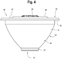
- the closure body 54 includes an outer wall 64 having a top end 66 defining a circular opening 68.
- the outer wall 64 further defines a sealed bottom end 70 (visible in Figs. 3 and 7 ).
- the outer wall 64 defines an interior surface 72 and an exterior surface 74.
- the interior of the body 54 defines a volume for storing a fluent substance.
- the body 54 has a cup-like shape, and the exterior surface 74 and defines a sloping, convex curve for accommodating differently-sized openings or neck finishes of different containers.
- the sealed bottom end 70 of the body 54 is adapted to be located at the opening of a container, such as the container 44 ( Fig. 10 ), so as to communicate with an interior of the container 44, as will be discussed in greater detail herein.
- An annular wall 65 ( Figs. 3 and 10 ) extends around the sealed bottom end 70 to further assist in centering and maintaining the dispensing system 40 at the openings of some containers.
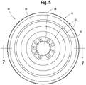
- the sealed bottom end 70 includes a frangible region of material in the form of a pair of reduced-thickness intersecting lines or line-like features 76 that are integrally molded with the body 54 to define lines of preferential weakness.
- Four petals 78 extend between the intersecting lines 76.
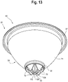
- the intersecting lines 76 are configured to rupture when engaged by the post 58 ( Figs. 11-14 ), which causes the petals 78 to open axially downward. Opening of the petals 78 defines a dispensing orifice 80 ( Fig. 13 ) in the bottom of the body 54 to permit flow of a substance from the interior of the body 54 to the exterior of the body 54.
- the inventors of the present invention have found that molding the sealed bottom end 70 with the lines 76 to define a frangible region or portion of the body 54 advantageously eliminates the need for a secondary, separate seal that would otherwise be required to cover a body having an open-molded bottom end. This may reduce the cost of manufacture and/or assembly of the system 40, and further may increase the robustness of the system 40, after it has been assembled and filled with a product, as well as during shipping, handling, and/or storage thereof.
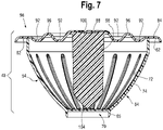
- the lid 56 includes a generally circular top deck 84 that terminates in a lip or skirt 86, which extends laterally beyond the top end of the body wall 64 when the lid 56 is assembled together with the body 54.
- the lid 56 includes a press portion 88 in the center of the top deck 84 which is surrounded by a pair of recessed annular portions or channels 92 that are separated by a raised annular portion or annular ridge 96. Together, the channels 92 and the ridge 96 provide the lid 56 with a spring-like, axial flexibility and permit the lid 56 to move from its unactuated, first position ( Fig. 7 ) to its actuated, second position ( Fig. 11 ) when a user presses against the press portion 88.
- the post 58 has a proximal end 100 that is connected to the bottom of the top deck 84 of the lid 56 and a distal end 104 located in a confronting position with respect to the sealed bottom end 70 when the lid 56 is in its first (unactuated) position.
- the post 58 defines a pair of intersecting walls 108, 110 (visible in Fig. 1 ) that taper to the distal end 104 of the post 58.
- the intersecting walls 108, 110 are aligned with the frangible intersecting lines 76 of the sealed bottom end 70 of the body 54, such that when the lid 56 is pressed into its actuated, second position by a user of the system 40, the post 58 breaches the frangible intersecting lines 76 of the sealed bottom end 70 of the body 54 (as illustrated in Figs. 11-14 ).
- the post 58 may instead be integral with, or connected to, only body 54 and not the lid 56.
- One advantage of such a configuration would be that the distal end of the post 58 does not need to pass through a substance stored within the body 54 when the lid 56 moves from its unactuated, first position to its actuated, second position to breach the sealed bottom end 70.
- the body 54 and the lid 56 are preferably molded as separate articles of manufacture and shipped to a filler facility with the liner 62.
- the filler facility then fills the body 54 with a pre-determined amount or dose of a substance (not illustrated).
- the liner 62 is then placed between the top end 66 of the wall 64 and the underside of the top deck 84 of the lid 56.
- the filled system 40 is then placed in an induction welding line to seal the liner 62 between both the lid 56 and the body 54 to form a completed package.
- a user such as a customer, will encounter the system 40 as shown in Fig. 2 , with the system 40 and the fluent substance contained and sealed therein defining a package.
- the system 40 would be typically used for dispensing a substance stored within the system 40 to be dissolved within a liquid (e.g., water) that is stored in a container 44.
- the user would first open the container 44 by removing the closure (not shown).
- the user would then orient the system 40 in an upright manner atop the upright, opened container 44 such that the curved exterior surface 74 of the body 54 would rest against the container 44 at its opening (see Figs. 8 , 9 , and 10 ).
- the sealed bottom end 70 of the body 54 is located at (e.g., above, within) the opening of the container 44.
- the convex curve of the exterior surface 74 helps to orient the body 54 and lid 56 such that so that the post 58 is generally upright and extends along the central axis 30 ( Fig. 10 ).
- the user can actuate the system 40 by gripping the body 54 and/or the container 44 and pressing with a thumb or finger against the press portion 88 on the lid 56.
- Application of a force upon the lid 56 will move the lid 56 from its first position ( Fig. 10 ) into its second position ( Fig. 11 ), and, in the process, drive down the post 58 along the axis 30.
- a sufficient pre-determined force is applied to the press portion 88 to deflect it axially inwardly, the post 58 will breach the sealed bottom end 70 of the body 54.
- the frangible portions along the intersecting lines 76 of the sealed bottom end 70 will rupture, and the four petals 78 will be forced by the post 58 to open axially downwardly toward the container 44 interior.
- a dispensing orifice 80 is thus created between the post 58 and the opened petals 78 to permit the fluent substance to exit the body 54 and enter the container 44.
- the one preferred form of the system 40 would be single-use, and the system 40 would be either recycled, or appropriately discarded, by the user after a single actuation or use.
- the user would typically close the container 44 with the original closure cap or lid (not illustrated) and then shake the closed container 44 to mix the dispensed substance together with the liquid of the container 44, and such a mixture would be consumed or otherwise used by the user.
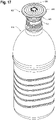
- Figs. 15-20 The dispensing system according to the present invention is illustrated in Figs. 15-20 and is designated generally by the numeral 40A.
- the numbered features of the second embodiment of the system 40A illustrated in Figs. 15-20 are designated generally with the suffix letter "A" and are analogous to features of the first embodiment of the system 40 that share the same number (without the suffix letter "A").
- the second embodiment of the system 40A includes the basic components of a body 54A and a lid 56A.
- the lid 56A includes an elongate post 58A.
- a ring-like foil liner 62A is sealed between the body 54A and the lid 56A to attach the lid 56A to the body 54A.
- the body 54A includes a sealed bottom end 70A that may be breached by movement of the lid 56A and the post 58A to dispense a substance stored within the body 54A.
- the second illustrated embodiment of the system 40A operates in a similar manner as described in detail above with respect to the first illustrated embodiment of the system 40.
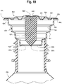
- the second embodiment of the system 40A differs from the first embodiment of the system 40 in that the second embodiment of the system 40A includes sealed bottom end 70A that has the form of a molded-open second opening or bottom aperture 120A in the body 54A, which is covered or sealed by a disc-like seal or bottom liner 124A.
- the bottom liner 124A is preferably formed from the same foil or metallic composite material as the ring-like liner 62A and may be sealed to the body 54A via an induction heating process, heat weld, adhesive, etc.
- the molded-open aperture 120A permits the body 54A to be advantageously filled with a substance from the bottom.
- a secondary liner 124A may greatly reduce the complexity and cost of the manufacturing process utilized for forming or molding the body 54A.
- the post 58A confronts and ruptures the bottom liner 124A to create a dispensing orifice 80A in the ruptured liner 124A.
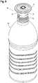
- the second embodiment of the system 40A further differs from the first embodiment of the system 40 in that the second embodiment of the system 40A includes an exterior surface 74A on the body 54A that has the form of a plurality of annular shoulders that increase in size from the sealed bottom end 70A to the top end 66A of the wall 64A.
- the inventors have found that providing the body 54A with an exterior surface 74A that includes a plurality of increasingly larger annular shoulders also accommodates the placement of the sealed bottom end 70A into or onto a large variety of standard and non-standard containers with varying sizes of openings or neck finishes. Furthermore, the user of the dispensing system 40A need not be educated about, or otherwise be made aware of, the variability of container openings or neck finishes on the market.
- the dispensing system may be configured with a body, lid, and a post, wherein the body has an open bottom end that may be assembled with a separate package or pod containing an additive or other substance to be dispensed.
- a system would include a lid covering the top end of the body, the lid having a press portion for being engaged by a user of the system, and a post extending from the lid beneath the press portion.
- the lid would have a first position and a second position moved relative to the first position, wherein in the second position at least a portion of the lid is deflected axially inwardly toward the open bottom end of the body.
- the pod could be removably attached to the body at the open bottom end thereof but retained with a sufficient force to hold the pod during the actuation process as next discussed.
- the pod would have a hollow body defining a volume for storing a substance.
- the pod hollow body would have a sealed top end and a sealed bottom end.
- the post would be configured such that movement from the unactuated, first position of the lid into said actuated, second position of the lid causes the post to breach the pod sealed top end and then the pod sealed bottom end to create a pod dispensing orifice in the pod sealed bottom end to accommodate movement of a substance out of the pod.
Landscapes
- Engineering & Computer Science (AREA)
- Mechanical Engineering (AREA)
- Closures For Containers (AREA)
- Containers And Packaging Bodies Having A Special Means To Remove Contents (AREA)
Claims (12)
- Abgabesystem (40, 40A) zur Verwendung bei der Abgabe einer Substanz, die innerhalb des Systems (40, 40A) gespeichert sein kann, das System (40, 40A) umfassend:einen Körper (54, 54A), der eine Außenwand (64, 64A) mit einer Außenfläche (74, 74A) und einer Innenfläche (72, 72A) aufweist, der ein Volumen zur Speicherung einer Substanz definiert, wobei die Außenwand (64, 64A) ein offenes oberes Ende (66, 66A) und ein dichtes unteres Ende (70, 70A) aufweist, wobei die Außenfläche (74A) der Außenwand (64A) wenigstens eine ringförmige Schulter definiert, um ein Halten des Körpers (54A) auf einem Behälter mit einer vorbestimmten Öffnungsgröße zu ermöglichen;einen flexiblen Deckel (56, 56A), der mit dem Körper (54, 54A) verbunden ist, um das offene obere Ende (66, 66A) abzudecken, wobei der Deckel (56, 56A) einen Drückabschnitt (88, 88A) zur Betätigung durch einen Benutzer des Systems (40, 40A) aufweist, wobei der Deckel (56, 56A) eine erste Position und eine zweite Position, die bezogen auf die erste Position bewegt ist, aufweist, wobei in der zweiten Position wenigstens ein Abschnitt des Deckels (56, 56A) in Richtung des dichten unteren Endes (70, 70A) des Körpers (54, 54A) ausgelenkt ist; undeinen Stift (58, 58A), der mit dem Deckel (56, 56A) verbunden ist, wobei der Stift (58, 58A) in der zweiten Position des Deckels (56, 56A) dazu ausgebildet ist, das dichte untere Ende (70, 70A) des Körpers (54, 54A) zu durchbrechen, um eine Abgabeöffnung (80, 80A) zu bilden, um Bewegung einer Substanz aus dem Körper (54, 54A) zu ermöglichen;wobei das Abgabesystem (40, 40A) dadurch gekennzeichnet ist, dass die Außenfläche (74A) der Außenwand (64A) eine Mehrzahl von ringförmigen Schultern definiert, die von dem dichten unteren Ende (70A) zum oberen Ende (66A) der Außenwand (64A) größer werden.
- Abgabesystem (40, 40A) nach Anspruch 1, wobei der Stift (58, 58A) einstückig mit dem Deckel (56, 56A) ausgebildet ist.
- Abgabesystem (40, 40A) nach einem der Ansprüche 1 bis 2, ferner umfassend eine Auskleidung (62, 62A), die dicht zwischen dem Deckel (56, 56A) und dem Körper (54, 54A) angebracht ist, um den Deckel (56, 56A) dicht mit dem Körper (54, 54A) zu verbinden.
- Abgabesystem (40) nach einem der Ansprüche 1 bis 3, wobei das dichte untere Ende (70) des Körpers (54) einen zerbrechbaren Abschnitt des Körpers (54) aufweist, der durch Bewegung des Stifts (58) mit dem Deckel (56) in der zweiten Position durchbrochen wird, um die Abgabeöffnung (80) zu schaffen.
- Abgabesystem (40) nach Anspruch 4, wobei der zerbrechbare Abschnitt des Körpers (54) ein Paar sich schneidender Linien (76) aus Material verringerter Dicke des Körpers (54) und vier bewegbare Blütenblätter (78), die zwischen den sich schneidenden Linien (76) definiert sind, aufweist.
- Abgabesystem (40A) nach einem der Ansprüche 1 bis 3, wobei das dichte untere Ende (70A) des Körpers (54A) eine Bodenöffnung (120A) in dem Körper (54A) und eine Bodenauskleidung (124A), die über der Bodenöffnung (120A) dicht angebracht ist, aufweist.
- Abgabesystem (40, 40A) nach einem der Ansprüche 1 bis 6, wobei der Deckel (56, 56A) in die erste Position vorgespannt ist.
- Abgabesystem (40, 40A) nach einem der Ansprüche 1 bis 7, wobei der Deckel (56, 56A) wenigstens einen erhöhten ringförmigen Abschnitt (96, 96A) und wenigstens einen vertieften ringförmigen Abschnitt (92, 92A) aufweist, die jeweils den Drückabschnitt (88, 88A) umgeben.
- Abgabesystem (40, 40A) nach einem der Ansprüche 1 bis 8 in Kombination mit einer fließenden Substanz, wobei das System (40, 40A) und die fließende Substanz zusammen eine Packung definieren.
- Abgabesystem (40, 40A) nach einem der Ansprüche 1 bis 9, wobei der Stift (58, 58A) die Form eines Paars langgestreckter, sich schneidender Wände (108, 110, 108A, 110A) aufweist, die an einem spitzen distalen Ende (104, 104A) enden.
- Abgabesystem (40, 40A) nach einem der Ansprüche 1 bis 10, wobei der Stift (58, 58A) mittels 2K-Spritzgießen an den Deckel (56, 56A) angeformt ist.
- Abgabesystem (40, 40A) nach einem der Ansprüche 1 bis 11, wobei der Körper (54, 54A) allgemein kegelförmig ist, wobei das obere Ende (66, 66A) größer als das dichte untere Ende (70, 70A) ist.
Applications Claiming Priority (2)
| Application Number | Priority Date | Filing Date | Title |
|---|---|---|---|
| US201862646137P | 2018-03-21 | 2018-03-21 | |
| PCT/US2019/023287 WO2019183301A1 (en) | 2018-03-21 | 2019-03-21 | Dispensing system |
Publications (3)
| Publication Number | Publication Date |
|---|---|
| EP3768603A1 EP3768603A1 (de) | 2021-01-27 |
| EP3768603A4 EP3768603A4 (de) | 2021-05-12 |
| EP3768603B1 true EP3768603B1 (de) | 2022-08-17 |
Family
ID=67986383
Family Applications (1)
| Application Number | Title | Priority Date | Filing Date |
|---|---|---|---|
| EP19771819.0A Active EP3768603B1 (de) | 2018-03-21 | 2019-03-21 | Ausgabesystem |
Country Status (6)
| Country | Link |
|---|---|
| US (1) | US11858684B2 (de) |
| EP (1) | EP3768603B1 (de) |
| CN (1) | CN112188983A (de) |
| ES (1) | ES2927363T3 (de) |
| MX (1) | MX2020009777A (de) |
| WO (1) | WO2019183301A1 (de) |
Families Citing this family (2)
| Publication number | Priority date | Publication date | Assignee | Title |
|---|---|---|---|---|
| EP4120878B1 (de) * | 2020-05-11 | 2025-12-31 | AptarGroup, Inc. | Abgabesystem |
| CN117163472B (zh) * | 2023-09-07 | 2025-02-11 | 万通(苏州)定量阀系统有限公司 | 一种可替换的分配装置 |
Family Cites Families (16)
| Publication number | Priority date | Publication date | Assignee | Title |
|---|---|---|---|---|
| US4634003A (en) * | 1984-08-22 | 1987-01-06 | Suntory Limited | Container for accommodating two kinds of liquids |
| US8839982B1 (en) * | 2011-05-27 | 2014-09-23 | Michael R. Anderson | Dispensing capsule with dual independent dispensing chambers |
| USD411288S (en) * | 1998-10-14 | 1999-06-22 | Gruber Systems, Inc. | Bowl |
| US6305576B1 (en) * | 2000-01-19 | 2001-10-23 | Nalge Nunc International Corporation | Cartridge for aseptically holding and dispensing a fluid material, and a container and method for aseptically holding and mixing the fluid material |
| US20020157970A1 (en) * | 2001-04-26 | 2002-10-31 | Carlson Stephen G. | Beverage flavor dispensing cap |
| US7004161B2 (en) * | 2001-05-02 | 2006-02-28 | Expressasia Berhad | Insertable thermotic module for self-heating cans |
| US20040026422A1 (en) * | 2002-07-09 | 2004-02-12 | Technology Center | Membrane penetrating closure with deformable top surface |
| FR2856985B1 (fr) | 2003-07-02 | 2006-06-09 | Seaquist General Plastics | Tete de distribution de produit fluide et utilisation d'une telle tete |
| ES2255353B1 (es) | 2003-07-29 | 2007-02-16 | Griffith Laboratories, S.A. | Tapa contenedora para envase. |
| ITMO20050057A1 (it) * | 2005-03-15 | 2006-09-16 | Lameplast Spa | Confezione per prodotti a preparazione estemporanea, particolarmente medicinali, farmaceutici,cosmetici o simili. |
| ATE456520T1 (de) * | 2005-04-14 | 2010-02-15 | Medisize Schweiz Ag | Flaschen- oder behälterverschluss zum zudosieren einer inhaltskomponente |
| US9550612B2 (en) * | 2005-07-01 | 2017-01-24 | Vitalia International Pty Ltd. | Closure with second dispensing compartment |
| US7874420B2 (en) * | 2009-02-09 | 2011-01-25 | Darren Coon | Affixable dispensing capsule |
| US8443970B2 (en) * | 2010-01-19 | 2013-05-21 | Karma Culture, Llc | Dispensing capsule |
| KR20120048758A (ko) | 2010-11-06 | 2012-05-16 | 이정민 | 본체를 통해 수용부를 개방하도록 된 이종물질 수용장치 |
| CN206045521U (zh) | 2016-08-31 | 2017-03-29 | 广东维中检测技术有限公司 | 一种沙芯漏斗 |
-
2019
- 2019-03-21 WO PCT/US2019/023287 patent/WO2019183301A1/en not_active Ceased
- 2019-03-21 US US16/982,151 patent/US11858684B2/en active Active
- 2019-03-21 MX MX2020009777A patent/MX2020009777A/es unknown
- 2019-03-21 EP EP19771819.0A patent/EP3768603B1/de active Active
- 2019-03-21 ES ES19771819T patent/ES2927363T3/es active Active
- 2019-03-21 CN CN201980034374.6A patent/CN112188983A/zh active Pending
Also Published As
| Publication number | Publication date |
|---|---|
| WO2019183301A1 (en) | 2019-09-26 |
| US20210024249A1 (en) | 2021-01-28 |
| US11858684B2 (en) | 2024-01-02 |
| ES2927363T3 (es) | 2022-11-04 |
| EP3768603A4 (de) | 2021-05-12 |
| CN112188983A (zh) | 2021-01-05 |
| BR112020019167A2 (pt) | 2021-01-05 |
| MX2020009777A (es) | 2020-12-11 |
| EP3768603A1 (de) | 2021-01-27 |
Similar Documents
| Publication | Publication Date | Title |
|---|---|---|
| US9694956B2 (en) | Dispensing and mixing device | |
| EP2670678B1 (de) | Spenderkappe für einen behälter | |
| US4442949A (en) | Tear open closure assembly | |
| US6450368B1 (en) | Device for the extemporaneous mixing of at least three products | |
| US20100140268A1 (en) | Dispensing closure with removable membrane | |
| EP3565765B1 (de) | Ausgabeverschluss | |
| US7810681B2 (en) | Internal container bore mount fitment | |
| US20190092539A1 (en) | Closure for a container | |
| US12454395B2 (en) | Dispensing closure | |
| US12600537B2 (en) | Dispensing closure | |
| US5012970A (en) | Cap with cutting ring for composite containers | |
| EP3768603B1 (de) | Ausgabesystem | |
| US5123573A (en) | Package for dispensing products capable of fluid motion | |
| US20250263209A1 (en) | Dispensing Closure With Tamper Evidence Features | |
| US12077356B2 (en) | Dispensing system | |
| CA1320458C (en) | Package for dispensing products capable of fluid motion | |
| US6929152B2 (en) | Assembly for the packaging and application of a fluid product | |
| JP7559193B2 (ja) | 二重加圧容器、吐出製品、吐出部材、吐出装置およびそれらを用いたディスペンサーシステム | |
| BR112020019167B1 (pt) | Sistema de aplicação para uso em aplicar uma substância que pode ser armazenada dentro do dito sistema | |
| WO2026072041A1 (en) | Closure with retention features | |
| GB2599754A (en) | A transit sealing plug | |
| HK1190686B (en) | Dispensing cap for a container |
Legal Events
| Date | Code | Title | Description |
|---|---|---|---|
| STAA | Information on the status of an ep patent application or granted ep patent |
Free format text: STATUS: THE INTERNATIONAL PUBLICATION HAS BEEN MADE |
|
| PUAI | Public reference made under article 153(3) epc to a published international application that has entered the european phase |
Free format text: ORIGINAL CODE: 0009012 |
|
| STAA | Information on the status of an ep patent application or granted ep patent |
Free format text: STATUS: REQUEST FOR EXAMINATION WAS MADE |
|
| 17P | Request for examination filed |
Effective date: 20201013 |
|
| AK | Designated contracting states |
Kind code of ref document: A1 Designated state(s): AL AT BE BG CH CY CZ DE DK EE ES FI FR GB GR HR HU IE IS IT LI LT LU LV MC MK MT NL NO PL PT RO RS SE SI SK SM TR |
|
| AX | Request for extension of the european patent |
Extension state: BA ME |
|
| A4 | Supplementary search report drawn up and despatched |
Effective date: 20210414 |
|
| RIC1 | Information provided on ipc code assigned before grant |
Ipc: B65D 47/20 20060101AFI20210408BHEP Ipc: B65D 51/28 20060101ALI20210408BHEP Ipc: B65D 81/32 20060101ALI20210408BHEP |
|
| DAV | Request for validation of the european patent (deleted) | ||
| DAX | Request for extension of the european patent (deleted) | ||
| GRAP | Despatch of communication of intention to grant a patent |
Free format text: ORIGINAL CODE: EPIDOSNIGR1 |
|
| STAA | Information on the status of an ep patent application or granted ep patent |
Free format text: STATUS: GRANT OF PATENT IS INTENDED |
|
| INTG | Intention to grant announced |
Effective date: 20220314 |
|
| GRAS | Grant fee paid |
Free format text: ORIGINAL CODE: EPIDOSNIGR3 |
|
| GRAA | (expected) grant |
Free format text: ORIGINAL CODE: 0009210 |
|
| STAA | Information on the status of an ep patent application or granted ep patent |
Free format text: STATUS: THE PATENT HAS BEEN GRANTED |
|
| AK | Designated contracting states |
Kind code of ref document: B1 Designated state(s): AL AT BE BG CH CY CZ DE DK EE ES FI FR GB GR HR HU IE IS IT LI LT LU LV MC MK MT NL NO PL PT RO RS SE SI SK SM TR |
|
| REG | Reference to a national code |
Ref country code: CH Ref legal event code: EP |
|
| REG | Reference to a national code |
Ref country code: DE Ref legal event code: R096 Ref document number: 602019018444 Country of ref document: DE |
|
| REG | Reference to a national code |
Ref country code: IE Ref legal event code: FG4D |
|
| REG | Reference to a national code |
Ref country code: AT Ref legal event code: REF Ref document number: 1512042 Country of ref document: AT Kind code of ref document: T Effective date: 20220915 |
|
| REG | Reference to a national code |
Ref country code: ES Ref legal event code: FG2A Ref document number: 2927363 Country of ref document: ES Kind code of ref document: T3 Effective date: 20221104 |
|
| REG | Reference to a national code |
Ref country code: NL Ref legal event code: MP Effective date: 20220817 |
|
| REG | Reference to a national code |
Ref country code: LT Ref legal event code: MG9D |
|
| PG25 | Lapsed in a contracting state [announced via postgrant information from national office to epo] |
Ref country code: SE Free format text: LAPSE BECAUSE OF FAILURE TO SUBMIT A TRANSLATION OF THE DESCRIPTION OR TO PAY THE FEE WITHIN THE PRESCRIBED TIME-LIMIT Effective date: 20220817 Ref country code: RS Free format text: LAPSE BECAUSE OF FAILURE TO SUBMIT A TRANSLATION OF THE DESCRIPTION OR TO PAY THE FEE WITHIN THE PRESCRIBED TIME-LIMIT Effective date: 20220817 Ref country code: PT Free format text: LAPSE BECAUSE OF FAILURE TO SUBMIT A TRANSLATION OF THE DESCRIPTION OR TO PAY THE FEE WITHIN THE PRESCRIBED TIME-LIMIT Effective date: 20221219 Ref country code: NO Free format text: LAPSE BECAUSE OF FAILURE TO SUBMIT A TRANSLATION OF THE DESCRIPTION OR TO PAY THE FEE WITHIN THE PRESCRIBED TIME-LIMIT Effective date: 20221117 Ref country code: NL Free format text: LAPSE BECAUSE OF FAILURE TO SUBMIT A TRANSLATION OF THE DESCRIPTION OR TO PAY THE FEE WITHIN THE PRESCRIBED TIME-LIMIT Effective date: 20220817 Ref country code: LV Free format text: LAPSE BECAUSE OF FAILURE TO SUBMIT A TRANSLATION OF THE DESCRIPTION OR TO PAY THE FEE WITHIN THE PRESCRIBED TIME-LIMIT Effective date: 20220817 Ref country code: LT Free format text: LAPSE BECAUSE OF FAILURE TO SUBMIT A TRANSLATION OF THE DESCRIPTION OR TO PAY THE FEE WITHIN THE PRESCRIBED TIME-LIMIT Effective date: 20220817 Ref country code: FI Free format text: LAPSE BECAUSE OF FAILURE TO SUBMIT A TRANSLATION OF THE DESCRIPTION OR TO PAY THE FEE WITHIN THE PRESCRIBED TIME-LIMIT Effective date: 20220817 |
|
| REG | Reference to a national code |
Ref country code: AT Ref legal event code: MK05 Ref document number: 1512042 Country of ref document: AT Kind code of ref document: T Effective date: 20220817 |
|
| PG25 | Lapsed in a contracting state [announced via postgrant information from national office to epo] |
Ref country code: PL Free format text: LAPSE BECAUSE OF FAILURE TO SUBMIT A TRANSLATION OF THE DESCRIPTION OR TO PAY THE FEE WITHIN THE PRESCRIBED TIME-LIMIT Effective date: 20220817 Ref country code: IS Free format text: LAPSE BECAUSE OF FAILURE TO SUBMIT A TRANSLATION OF THE DESCRIPTION OR TO PAY THE FEE WITHIN THE PRESCRIBED TIME-LIMIT Effective date: 20221217 Ref country code: HR Free format text: LAPSE BECAUSE OF FAILURE TO SUBMIT A TRANSLATION OF THE DESCRIPTION OR TO PAY THE FEE WITHIN THE PRESCRIBED TIME-LIMIT Effective date: 20220817 Ref country code: GR Free format text: LAPSE BECAUSE OF FAILURE TO SUBMIT A TRANSLATION OF THE DESCRIPTION OR TO PAY THE FEE WITHIN THE PRESCRIBED TIME-LIMIT Effective date: 20221118 |
|
| PG25 | Lapsed in a contracting state [announced via postgrant information from national office to epo] |
Ref country code: SM Free format text: LAPSE BECAUSE OF FAILURE TO SUBMIT A TRANSLATION OF THE DESCRIPTION OR TO PAY THE FEE WITHIN THE PRESCRIBED TIME-LIMIT Effective date: 20220817 Ref country code: RO Free format text: LAPSE BECAUSE OF FAILURE TO SUBMIT A TRANSLATION OF THE DESCRIPTION OR TO PAY THE FEE WITHIN THE PRESCRIBED TIME-LIMIT Effective date: 20220817 Ref country code: DK Free format text: LAPSE BECAUSE OF FAILURE TO SUBMIT A TRANSLATION OF THE DESCRIPTION OR TO PAY THE FEE WITHIN THE PRESCRIBED TIME-LIMIT Effective date: 20220817 Ref country code: CZ Free format text: LAPSE BECAUSE OF FAILURE TO SUBMIT A TRANSLATION OF THE DESCRIPTION OR TO PAY THE FEE WITHIN THE PRESCRIBED TIME-LIMIT Effective date: 20220817 Ref country code: AT Free format text: LAPSE BECAUSE OF FAILURE TO SUBMIT A TRANSLATION OF THE DESCRIPTION OR TO PAY THE FEE WITHIN THE PRESCRIBED TIME-LIMIT Effective date: 20220817 |
|
| REG | Reference to a national code |
Ref country code: DE Ref legal event code: R097 Ref document number: 602019018444 Country of ref document: DE |
|
| PG25 | Lapsed in a contracting state [announced via postgrant information from national office to epo] |
Ref country code: SK Free format text: LAPSE BECAUSE OF FAILURE TO SUBMIT A TRANSLATION OF THE DESCRIPTION OR TO PAY THE FEE WITHIN THE PRESCRIBED TIME-LIMIT Effective date: 20220817 Ref country code: EE Free format text: LAPSE BECAUSE OF FAILURE TO SUBMIT A TRANSLATION OF THE DESCRIPTION OR TO PAY THE FEE WITHIN THE PRESCRIBED TIME-LIMIT Effective date: 20220817 |
|
| P01 | Opt-out of the competence of the unified patent court (upc) registered |
Effective date: 20230509 |
|
| PLBE | No opposition filed within time limit |
Free format text: ORIGINAL CODE: 0009261 |
|
| STAA | Information on the status of an ep patent application or granted ep patent |
Free format text: STATUS: NO OPPOSITION FILED WITHIN TIME LIMIT |
|
| PG25 | Lapsed in a contracting state [announced via postgrant information from national office to epo] |
Ref country code: AL Free format text: LAPSE BECAUSE OF FAILURE TO SUBMIT A TRANSLATION OF THE DESCRIPTION OR TO PAY THE FEE WITHIN THE PRESCRIBED TIME-LIMIT Effective date: 20220817 |
|
| 26N | No opposition filed |
Effective date: 20230519 |
|
| PG25 | Lapsed in a contracting state [announced via postgrant information from national office to epo] |
Ref country code: SI Free format text: LAPSE BECAUSE OF FAILURE TO SUBMIT A TRANSLATION OF THE DESCRIPTION OR TO PAY THE FEE WITHIN THE PRESCRIBED TIME-LIMIT Effective date: 20220817 |
|
| PG25 | Lapsed in a contracting state [announced via postgrant information from national office to epo] |
Ref country code: MC Free format text: LAPSE BECAUSE OF FAILURE TO SUBMIT A TRANSLATION OF THE DESCRIPTION OR TO PAY THE FEE WITHIN THE PRESCRIBED TIME-LIMIT Effective date: 20220817 |
|
| REG | Reference to a national code |
Ref country code: CH Ref legal event code: PL |
|
| REG | Reference to a national code |
Ref country code: BE Ref legal event code: MM Effective date: 20230331 |
|
| PG25 | Lapsed in a contracting state [announced via postgrant information from national office to epo] |
Ref country code: LU Free format text: LAPSE BECAUSE OF NON-PAYMENT OF DUE FEES Effective date: 20230321 |
|
| REG | Reference to a national code |
Ref country code: IE Ref legal event code: MM4A |
|
| PG25 | Lapsed in a contracting state [announced via postgrant information from national office to epo] |
Ref country code: LI Free format text: LAPSE BECAUSE OF NON-PAYMENT OF DUE FEES Effective date: 20230331 Ref country code: IE Free format text: LAPSE BECAUSE OF NON-PAYMENT OF DUE FEES Effective date: 20230321 Ref country code: CH Free format text: LAPSE BECAUSE OF NON-PAYMENT OF DUE FEES Effective date: 20230331 |
|
| PG25 | Lapsed in a contracting state [announced via postgrant information from national office to epo] |
Ref country code: BE Free format text: LAPSE BECAUSE OF NON-PAYMENT OF DUE FEES Effective date: 20230331 |
|
| PG25 | Lapsed in a contracting state [announced via postgrant information from national office to epo] |
Ref country code: BG Free format text: LAPSE BECAUSE OF FAILURE TO SUBMIT A TRANSLATION OF THE DESCRIPTION OR TO PAY THE FEE WITHIN THE PRESCRIBED TIME-LIMIT Effective date: 20220817 |
|
| PG25 | Lapsed in a contracting state [announced via postgrant information from national office to epo] |
Ref country code: BG Free format text: LAPSE BECAUSE OF FAILURE TO SUBMIT A TRANSLATION OF THE DESCRIPTION OR TO PAY THE FEE WITHIN THE PRESCRIBED TIME-LIMIT Effective date: 20220817 |
|
| PGFP | Annual fee paid to national office [announced via postgrant information from national office to epo] |
Ref country code: DE Payment date: 20250327 Year of fee payment: 7 |
|
| PGFP | Annual fee paid to national office [announced via postgrant information from national office to epo] |
Ref country code: FR Payment date: 20250325 Year of fee payment: 7 |
|
| PGFP | Annual fee paid to national office [announced via postgrant information from national office to epo] |
Ref country code: GB Payment date: 20250327 Year of fee payment: 7 |
|
| PGFP | Annual fee paid to national office [announced via postgrant information from national office to epo] |
Ref country code: ES Payment date: 20250401 Year of fee payment: 7 |
|
| PGFP | Annual fee paid to national office [announced via postgrant information from national office to epo] |
Ref country code: IT Payment date: 20250422 Year of fee payment: 7 |
|
| PG25 | Lapsed in a contracting state [announced via postgrant information from national office to epo] |
Ref country code: CY Free format text: LAPSE BECAUSE OF FAILURE TO SUBMIT A TRANSLATION OF THE DESCRIPTION OR TO PAY THE FEE WITHIN THE PRESCRIBED TIME-LIMIT; INVALID AB INITIO Effective date: 20190321 |
|
| PG25 | Lapsed in a contracting state [announced via postgrant information from national office to epo] |
Ref country code: HU Free format text: LAPSE BECAUSE OF FAILURE TO SUBMIT A TRANSLATION OF THE DESCRIPTION OR TO PAY THE FEE WITHIN THE PRESCRIBED TIME-LIMIT; INVALID AB INITIO Effective date: 20190321 |
|
| PG25 | Lapsed in a contracting state [announced via postgrant information from national office to epo] |
Ref country code: TR Free format text: LAPSE BECAUSE OF FAILURE TO SUBMIT A TRANSLATION OF THE DESCRIPTION OR TO PAY THE FEE WITHIN THE PRESCRIBED TIME-LIMIT Effective date: 20220817 |