EP3768622B1 - Maschine und verfahren zur positionierung von gegenständen - Google Patents
Maschine und verfahren zur positionierung von gegenständen Download PDFInfo
- Publication number
- EP3768622B1 EP3768622B1 EP19705929.8A EP19705929A EP3768622B1 EP 3768622 B1 EP3768622 B1 EP 3768622B1 EP 19705929 A EP19705929 A EP 19705929A EP 3768622 B1 EP3768622 B1 EP 3768622B1
- Authority
- EP
- European Patent Office
- Prior art keywords
- transfer
- conveyor belt
- objects
- carriers
- conveyor
- Prior art date
- Legal status (The legal status is an assumption and is not a legal conclusion. Google has not performed a legal analysis and makes no representation as to the accuracy of the status listed.)
- Active
Links
Images




Classifications
-
- B—PERFORMING OPERATIONS; TRANSPORTING
- B65—CONVEYING; PACKING; STORING; HANDLING THIN OR FILAMENTARY MATERIAL
- B65G—TRANSPORT OR STORAGE DEVICES, e.g. CONVEYORS FOR LOADING OR TIPPING, SHOP CONVEYOR SYSTEMS OR PNEUMATIC TUBE CONVEYORS
- B65G54/00—Non-mechanical conveyors not otherwise provided for
- B65G54/02—Non-mechanical conveyors not otherwise provided for electrostatic, electric, or magnetic
-
- B—PERFORMING OPERATIONS; TRANSPORTING
- B65—CONVEYING; PACKING; STORING; HANDLING THIN OR FILAMENTARY MATERIAL
- B65G—TRANSPORT OR STORAGE DEVICES, e.g. CONVEYORS FOR LOADING OR TIPPING, SHOP CONVEYOR SYSTEMS OR PNEUMATIC TUBE CONVEYORS
- B65G47/00—Article or material-handling devices associated with conveyors; Methods employing such devices
- B65G47/22—Devices influencing the relative position or the attitude of articles during transit by conveyors
- B65G47/24—Devices influencing the relative position or the attitude of articles during transit by conveyors orientating the articles
-
- B—PERFORMING OPERATIONS; TRANSPORTING
- B25—HAND TOOLS; PORTABLE POWER-DRIVEN TOOLS; MANIPULATORS
- B25J—MANIPULATORS; CHAMBERS PROVIDED WITH MANIPULATION DEVICES
- B25J9/00—Program-controlled manipulators
- B25J9/003—Program-controlled manipulators having parallel kinematics
-
- B—PERFORMING OPERATIONS; TRANSPORTING
- B25—HAND TOOLS; PORTABLE POWER-DRIVEN TOOLS; MANIPULATORS
- B25J—MANIPULATORS; CHAMBERS PROVIDED WITH MANIPULATION DEVICES
- B25J9/00—Program-controlled manipulators
- B25J9/0093—Program-controlled manipulators co-operating with conveyor means
-
- B—PERFORMING OPERATIONS; TRANSPORTING
- B25—HAND TOOLS; PORTABLE POWER-DRIVEN TOOLS; MANIPULATORS
- B25J—MANIPULATORS; CHAMBERS PROVIDED WITH MANIPULATION DEVICES
- B25J9/00—Program-controlled manipulators
- B25J9/16—Program controls
- B25J9/1694—Program controls characterised by use of sensors other than normal servo-feedback from position, speed or acceleration sensors, perception control, multi-sensor controlled systems, sensor fusion
- B25J9/1697—Vision controlled systems
-
- B—PERFORMING OPERATIONS; TRANSPORTING
- B65—CONVEYING; PACKING; STORING; HANDLING THIN OR FILAMENTARY MATERIAL
- B65G—TRANSPORT OR STORAGE DEVICES, e.g. CONVEYORS FOR LOADING OR TIPPING, SHOP CONVEYOR SYSTEMS OR PNEUMATIC TUBE CONVEYORS
- B65G47/00—Article or material-handling devices associated with conveyors; Methods employing such devices
- B65G47/74—Feeding, transfer, or discharging devices of particular kinds or types
- B65G47/90—Devices for picking-up and depositing articles or materials
Definitions
- the present invention relates to a machine and a method for positioning, by means of robotic handling, objects of different shapes and sizes, such as packaging, jars, bottles, industrial parts and components, etc., which need to be placed in a certain position, especially in a vertical and/or upright position, for the subsequent handling and/or industrial processing thereof, such as being packaged, packed, assembled, labelled, etc.
- the fundamental concept consists of distributing the objects in a disorderly (random) manner on a conveyor belt, the advancing of which makes said objects pass beneath a machine vision camera such that the shape and position thereof are identified.
- the coordinates of said objects are sent to one or more robots, which dynamically go to search for said objects in movement, collecting them from the conveyor belt, whether by suction or grabbing them, in order to subsequently move them to the delivery area.
- the objects collected by the robots are deposited directly on a second conveyor belt in an ordered manner and in a specific position. Said second conveyor belt facilitates the outlet thereof from the machine to lead them to the following process.
- Document WO2014/064593A1 shows an example of these types of machines and methods for positioning objects.
- bin picking consisting of the ability to collect an element directly from a container or bin where it is heaped/unordered, by means of the use of 3D machine vision. In this manner, a portion of the process is eliminated along with the associated cost thereof, even though the speed with which the robot can act is penalised.
- This aspect is precisely the one that currently limits the use of robots, especially for handling light and unstable elements. Meaning, even though the robot is very fast, in the end, in the process of delivering to the conveyor belt, it cannot just drop the object, but rather it must accompany it for a time on the conveyor belt until it matches the speed thereof, such that upon dropping the object inertia is not produced which would cause imbalance in said object, making it fall.
- Document US2012/330457A1 discloses a machine for positioning objects, comprising a first conveyor belt configured to receive a plurality of objects; machine vision means configured to identify the position and the shape of the objects arranged on the first conveyor belt; robotic collection means configured to collect the objects from the first conveyor belt according to the information received from the machine vision means; a second conveyor belt configured to enable the outlet of said objects; and a transfer conveyor that has a plurality of transfer carriers configured to move in a closed loop through it enabling the speed and position thereof to be controlled, wherein said transfer carriers are configured to receive the objects coming from the robotic collection means and deliver said objects to the second conveyor belt; wherein the transfer carriers are configured to receive the objects coming from the robotic collection means in a horizontal position and deliver said objects to the second conveyor belt in a vertical position; wherein the transfer conveyor is arranged in a vertical position between the first conveyor belt and the second conveyor belt.
- Said document further discloses a corresponding method for positioning objects.
- the machine for positioning objects of the present invention as defined in claim 1 resolves the previously explained problems in robotic applications, thanks to a simplified and compact technical solution that enables the positioning of the objects without needing to accompany them with the robot that collects them from the random position thereof. With this the maximum transfer speed is considerably increased.
- the machine and the method for positioning objects of the present invention enables a greater diversity of objects to be positioned at a faster speed than the current robotic applications.
- the machine for positioning objects of claim 1 comprises, amongst others:
- the arrangement of the objects on the first conveyor belt is random, especially when plastic packaging or other light objects are handled.
- the objects can also be arranged on the first conveyor belt in an orderly manner, for example, supplied in pallets for carrying objects, which tends to be the case for objects made out of glass or other fragile objects.
- the collection of the objects by the robotic collection means generally tends to be selective, meaning, based on certain conditions. For example; collecting the objects that are closest to the robotic collection means; collecting only the objects that arrive in a certain orientation and/or position, or have certain characteristics; collecting the objects that are easiest to deliver to the first conveyor belt, etc.
- the machine for positioning objects of the present invention comprises a transfer conveyor that has a plurality of transfer carriers configured to move in a closed loop through it enabling the speed and position thereof to be controlled independently, where said transfer carriers are configured to receive the objects coming from the robotic collection means and deliver said objects to the second conveyor belt.
- the transfer carriers move on the transfer conveyor, also called an intelligent conveyor, by means of magnetic induction. Said independent carriers run in a controlled manner along the transfer conveyor, being able to be individually controlled at will by the user, regarding the position, speed, acceleration and strength thereof. Therefore, it enables a programmable sequential movement of the distinct transfer carriers.
- the processes for collecting the objects coming from the robotic collection means and delivering them to the second conveyor belt are performed consecutively. Nevertheless, in other application cases, it is also possible to perform other intermediate operations or processes between the collection and the delivery of said objects. For example; processes of assembling, filling, blowing, closing., which can be carried out in the same transfer conveyor, as the objects are transported by the transfer carriers.
- the length and the path of the transfer conveyor adapt in order to make room for the distinct intermediate operations of the objects before the delivery thereof on the second conveyor belt (outlet band).
- the transfer carriers are configured to receive the objects coming from the robotic collection means in a predetermined position and deliver said objects to the second conveyor belt in a vertical position, meaning, upright or resting on the main supporting base thereof.
- the transfer carriers are configured to work in collaboration with each other, enabling the securing of an object coming from the robotic collection means by the pressure exerted on it by two adjacent transfer carriers between which said object is arranged, and the subsequent delivery thereof to the second conveyor belt after releasing said pressure.
- the transfer carriers are not conditioned by the geometry of the object.
- This embodiment enables a wide variety of objects with different shapes and/or sizes to be worked with without needing to change accessories.
- the operating sequence can be programmed and memorised for each distinct object, such that, the change from one object to another can be performed instantaneously and automatically by selecting each object format from the control panel of the machine.
- the transfer carriers are made up of first transfer carriers and by second transfer carriers, where the first transfer carriers and the second transfer carriers are distributed in an alternating manner along the transfer conveyor.
- each first transfer carrier comprises:
- each second transfer carrier comprises:
- the transfer carriers are made up of third transfer carriers, where each of them comprises a gripper configured to grip an object coming from the robotic collection means and deliver said object to the second conveyor belt.
- This embodiment also enables a considerable variety of objects with different shapes and/or sizes to be worked with without needing to change accessories. Nevertheless, unlike the first embodiment, the transfer carriers work independently from each other. This enables the number of operations to be carried out by each of the transfer carriers during the collection and delivery of the objects to be reduced.
- the gripper is made up of:
- the transfer conveyor comprises one or more opening cams in a static position distributed along it, configured to come into contact with the dynamic gripper portion as the third transfer carrier passes and to cause the rotation thereof with respect to the joint. Said rotation enables the gripper to be opened in order to collect or deliver the object.
- the transfer conveyor admits, for all the previously commented preferred embodiments, different assembly and/or location arrangements of said conveyor with respect to the first conveyor belt and the second conveyor belt. Said assembly and/or location arrangements have an influence on the space occupied by the machine, the compactness thereof and the accessibility of the components thereof.
- the transfer conveyor is arranged in a tilted position between the first conveyor belt and the second conveyor belt. This first arrangement is very compact and offers good accessibility to the main components of the machine.
- the transfer carriers form a tilting angle with respect to the transfer conveyor, for example, of 45° or 135° staying vertically arranged in a collection position, and horizontally in a delivery position.
- the transfer conveyor is arranged in a vertical position between the first conveyor belt and the second conveyor belt. This second arrangement implies a lesser amount of space occupied by the machine with respect to the previous arrangement.
- the transfer carriers can receive the objects coming from the robotic collection means in an inverted vertical position, and deliver them in the vertical position after a 180° rotation of the transfer carriers along the transfer conveyor.
- This inverted vertical position is ideal for the application of processes for blowing and/or emptying the packaging, normally focused on the cleaning thereof.
- the main components of the machine are at a less accessible height.
- the transfer carriers are arranged vertically or horizontally.
- the machine for positioning objects of the present invention can have built-in or external means of supplying the objects to be positioned. This means that the objects can arrive at the first conveyor belt from a containment or storage area for them that is integrated in the machine, or from an external location.
- the machine For more compactness, versatility and autonomy of the machine, it preferably has built-in supply means for the objects to be positioned.
- the machine comprises:
- the collection of the objects by the robotic collection means can be selective, meaning, of those objects that meet certain conditions. Such that the rest of the objects must return to the processing line and/or the supply means.
- the machine comprises a return track adjacent to a second end of the first conveyor belt, configured to receive the objects that arrive at said second end and return them to the supply bin using gravity.
- the delivery of the objects to the second conveyor belt can be performed directly or indirectly with respect to it.
- the objects are delivered directly to the second conveyor belt, meaning, by depositing them directly on the second conveyor belt.
- the objects are delivered indirectly to the second conveyor belt, meaning, by depositing them onto a supporting base, also called a puck, transported by said second conveyor belt.
- a supporting base also called a puck
- These pucks offer a greater stability to the objects, once delivered to the second conveyor belt, which enables the delivery speed thereof to be increased and, therefore, the number of objects positioned per unit of time as well.
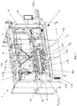
- FIGS 1 - 6 show different views of the machine (1) of the present invention, according to the first aspect.
- said machine (1) comprises:
- the machine (1) for positioning objects of the present invention comprises a transfer conveyor (6) that has a plurality of transfer carriers (7, 7a, 7b) configured to move in a closed loop through it enabling the speed and position thereof to be controlled independently, where said transfer carriers (7, 7a, 7b) are configured to receive the objects (O) coming from the robotic collection means (4) and deliver said objects (O) to the second conveyor belt (5).
- the machine vision means (3) comprise a machine vision camera and the robotic collection means (4) comprise two delta-type robotic arms, enabling a production capacity greater than 200 objects positioned per minute for the machine (1).
- the transfer carriers (7, 7a, 7b) are configured to receive the objects (O) coming from the robotic collection means (4) in a horizontal position (O H ) and deliver said objects (O) to the second conveyor belt (5) in a vertical position (Ov), meaning, resting on the main supporting base thereof.
- the transfer carriers (7, 7a, 7b) are configured to work in collaboration with each other, enabling the securing of an object (O) coming from the robotic collection means (4) by the pressure exerted on it by two adjacent transfer carriers (7, 7a, 7b) between which said object (O) is arranged, and the subsequent delivery thereof to the second conveyor belt (5) after releasing said pressure.
- the transfer conveyor (6) is arranged in a tilted position (6 l ) between the first conveyor belt (2) and the second conveyor belt (5).
- the transfer carriers (7, 7a, 7b) form a tilt angle ( ⁇ 7 ) with respect to the transfer conveyor (6) of 135°, being arranged vertically in a collection position (P R ), and horizontally in a delivery position (P E ), Figure 3 .
- the transfer carriers (7, 7a, 7b) receive the objects (O) coming from the robotic collection means (4) in a horizontal position (O H ) and deliver them in a vertical position (Ov) to the second conveyor belt (5).
- the machine (1) comprises:
- the machine (1) comprises a return track (12) adjacent to a second end (22) of the first conveyor belt (2), configured to receive the objects (O) that arrive at said second end (22) and return them to the supply bin (10) using gravity.
- the delivery of the objects (O) to the second conveyor belt (5) is performed directly.
- the transfer carriers (7) are made up of first transfer carriers (7a) and by second transfer carriers (7b), where the first transfer carriers (7a) and the second transfer carriers (7b) are distributed in an alternating manner along the transfer conveyor (6).
- Each first transfer carrier (7a) comprises:
- Each second transfer carrier (7b) comprises:
- Figure 7 shows a view of a machine that does not from part of the present invention, wherein the transfer conveyor (6) is arranged in a horizontal position (6 H ) between the first conveyor belt (2) and the second conveyor belt (5). In turn, the transfer carriers (7) are arranged horizontally.
- the objects (O) are collected in a vertical position (Ov) and are delivered in a likewise vertical position (Ov).
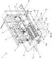
- Figures 8 - 10 show different views of the machine (1) of the present invention, according to the second aspect.
- the transfer conveyor (6) is arranged in a vertical position (6v) between the first conveyor belt (2) and the second conveyor belt (5).
- the transfer carriers (7) receive the objects (O) coming from the robotic collection means (4) in an inverted vertical position (O IN ), and deliver them in a vertical position (Ov) after a 180° rotation of the transfer carriers (7) along the transfer conveyor (6).
- the end portion, or securing portion, of the transfer carriers (7) is arranged horizontally, Figure 9 , or vertically, Figure 10 .
- Said method additionally comprises the following steps:
- Steps d) and e) respectively comprise the following steps:
- Steps d) and e) respectively comprise the following steps:
- Step f) comprises the following steps:
- FIG 11 is a detail view of the machine (1), according to a second embodiment of the transfer carriers (7).
- the transfer carriers (7) are made up of third transfer carriers (7c), where each of them comprises a gripper (70c) configured to grip an object (O) coming from the robotic collection means (4) and deliver said object (O) to the second conveyor belt (5).
- the gripper (70c) is made up of:
- the gripper (70c) can admit multiple possible mechanical configurations.
- the gripper (70c) can comprise one or more mobile portions in which all of them enable the function to be performed; on one hand, securing the object (O) in one point; and on the other, the releasing thereof onto the outlet conveyor belt (5).
- the transfer conveyor (6) comprises one or more opening cams (61) in a static position, configured to come into contact with the dynamic gripper portion (72c) as the third transfer carrier (7c) passes and to cause the rotation thereof with respect to the joint (73c) in order to open the gripper (70c).
- step f) comprises the following steps:
- Figure 12 is a detail view of the machine (1), wherein the objects (O) are placed on supporting bases (13) or pucks when the they are delivered to the second conveyor belt (5).
Landscapes
- Engineering & Computer Science (AREA)
- Mechanical Engineering (AREA)
- Robotics (AREA)
- Specific Conveyance Elements (AREA)
- Attitude Control For Articles On Conveyors (AREA)
- Intermediate Stations On Conveyors (AREA)
- Control Of Conveyors (AREA)
Claims (16)
- Maschine zur Positionierung von Gegenständen, umfassend- ein erstes Förderband (2), das zur Aufnahme einer Vielzahl von Gegenständen (O) ausgelegt ist;- eine Vorrichtung für industrielle Bildverarbeitung (3), die dazu ausgelegt ist, Position und Form der auf dem ersten Förderband (2) befindlichen Gegenstände (O) zu ermitteln;- eine robotisierte Einholvorrichtung (4), die dazu ausgelegt ist, die Gegenstände (O) entsprechend den von der Bildverarbeitungsvorrichtung (3) empfangenen Informationen vom ersten Förderband (2) einzuholen;- ein zweites Förderband (5), das dazu ausgelegt ist, den Austrag der genannten Gegenstände (O) zu ermöglichen; und- einen Übergaberförderer (6) mit einer Vielzahl von Übergabemitnehmern (7, 7a, 7b, 7c), die so ausgelegt sind, dass sie sich mittels magnetischer Induktion in einer geschlossenen Schleife durch diesen bewegen, wodurch ihre Geschwindigkeit und Position individuell gesteuert werden kann, wobei die genannten Übergabemitnehmer (7, 7a, 7b, 7c) zur Aufnahme der von der robotisierten Einholvorrichtung (4) kommenden Gegenstände (O) und zur Abgabe der genannten Gegenstände (O) an das zweite Förderband (5) ausgelegt sind, wobei der Übergabeförderer (6) in einer geneigten Position (6l) zwischen dem ersten Förderband (2) und dem zweiten Förderband (5) angeordnet ist und die Übergabemitnehmer (7, 7a, 7b, 7c) so ausgelegt sind, dass sie die von der robotisierten Einholvorrichtung (4) kommenden Gegenstände (O) in einer horizontalen Position (OH) aufnehmen und die genannten Gegenstände (O) in einer vertikalen Position (Ov) an das zweite Förderband (5) abgeben; oder wobei der Übergabeförderer (6) in einer vertikalen Position (6v) zwischen dem ersten Förderband (2) und dem zweiten Förderband (5) angeordnet ist und die Übergabemitnehmer (7, 7a, 7b, 7c) so ausgelegt sind, dass sie die von der robotisierten Einholvorrichtung (4) kommenden Gegenstände (O) in einer umgekehrt vertikalen Position (OIN) aufnehmen und die genannten Gegenstände (O) in einer vertikalen Position (Ov) an das zweite Förderband (5) abgeben.
- Maschine zur Positionierung von Gegenständen nach Anspruch 1, dadurch gekennzeichnet, dass die Übergabemitnehmer (7, 7a, 7b) so ausgelegt sind, dass sie zusammenwirken und durch den Druck, der von zwei benachbarten Übergabemitnehmern (7, 7a, 7b), zwischen denen ein von der robotisierten Einholvorrichtung (4) kommender Gegenstand (O) angeordnet ist, auf diesen ausgeübt wird, die Fixierung des genannten Gegenstands (O) und nach Aufhebung des genannten Drucks seine anschließende Abgabe an das zweite Förderband (5) ermöglichen.
- Maschine zur Positionierung von Gegenständen nach einem der Ansprüche 1 bis 2, dadurch gekennzeichnet, dass die Übergabemitnehmer (7) aus Folgendem bestehen:- ersten Übergabemitnehmern (7a); und- zweiten Übergabemitnehmern (7b);wobei die ersten Übergabemitnehmer (7a) und die zweiten Übergabemitnehmer (7b) abwechselnd entlang des Übergabeförderers (6) angeordnet sind.
- Maschine zur Positionierung von Gegenständen nach Anspruch 3, dadurch gekennzeichnet, dass jeder Übergabemitnehmer (7a) Folgendes umfasst:- ein erstes Aufnahmeprofil (8a), das zur Aufnahme eines ersten Gegenstands (OA) ausgelegt ist; und- ein zusätzliches erstes Aufnahmeprofil (9a), das sich vom ersten Aufnahmeprofil (8a) unterscheidet und diesem gegenüberliegt und zur Aufnahme eines zweiten Gegenstands (OB) ausgelegt ist;und dadurch, dass jeder zweite Übergabemitnehmer (7b) Folgendes umfasst:- ein zweites Aufnahmeprofil (8b), das zur Aufnahme des ersten Gegenstands (OA) ausgelegt ist; und- ein zusätzliches zweites Aufnahmeprofil (9b), das sich vom zweiten Aufnahmeprofil (8b) unterscheidet und diesem gegenüberliegt und zur Aufnahme des zweiten Gegenstands (OB) ausgelegt ist.
- Maschine zur Positionierung von Gegenständen nach einem der Ansprüche 1 bis 2, dadurch gekennzeichnet, dass die Übergabemitnehmer (7) aus dritten Übergabemitnehmern (7c) bestehen, von denen jeder einen Greifer (70c), der zum Ergreifen eines von der robotisierten Einholvorrichtung (4) kommenden Gegenstands (O) und Übergeben des genannten Gegenstands (O) an das zweite Förderband (5) ausgelegt ist, umfasst.
- Maschine zur Positionierung von Gegenständen nach Anspruch 5, dadurch gekennzeichnet, dass der Greifer (70c) aus Folgendem besteht:- einem statischen Greiferteil (71c), der an dem dritten Übergabemitnehmer (7c) befestigt ist; und- einem dynamischen Greiferteil (72c), der mittels eines Gelenks (73c) mit dem dritten Übergabemitnehmer (7c) verbunden ist;und dadurch, dass der Übergabeförderer (6) einen Öffnungsnocken (61) in einer statischen Position umfasst, der so ausgelegt ist, dass er beim Vorbeilauf des dritten Übergabemitnehmers (7c) mit dem dynamischen Greiferteil (72c) in Kontakt kommt und dessen Drehung um das Gelenk (73c) zwecks Öffnung des Greifers (70c) bewirkt.
- Maschine zur Positionierung von Gegenständen nach einem der Ansprüche 1 bis 6, dadurch gekennzeichnet, dass die Übergabemitnehmer (7, 7a, 7b, 7c) einen Neigungswinkel (θ7) relativ zum Übergabeförderer (6) bilden, wobei sie bei Anordnung des Übergabeförderers (6) in einer geneigten Position (6l) zwischen dem ersten Förderband (2) und dem zweiten Förderband (5) in der Aufnahmeposition (PR) vertikal und in der Abgabeposition (PE) horizontal angeordnet sind.
- Maschine zur Positionierung von Gegenständen nach einem der Ansprüche 1 bis 6, dadurch gekennzeichnet, dass die Übergabemitnehmer (7, 7a, 7b, 7c) bei Anordnung des Übergabeförderers (6) in einer geneigten Position (6v) zwischen dem ersten Förderband (2) und dem zweiten Förderband (5) vertikal oder horizontal angeordnet sind.
- Maschine zur Positionierung von Gegenständen nach einem der Ansprüche 1 bis 8, dadurch gekennzeichnet, dass sie Folgendes umfasst:- einen Vorratsbehälter (10), der zum ungeordneten Vorhalten der Gegenstände (O) ausgelegt ist; und- einen Heber (11), der zum Entnehmen der Gegenstände (O) aus dem Vorratsbehälter (10) und deren Andordnen auf einem ersten Ende (21) des ersten Förderbandes (2) ausgelegt ist.
- Maschine zur Positionierung von Gegenständen nach Anspruch 9, dadurch gekennzeichnet, dass sie Folgendes umfasst:- eine an ein zweites Ende (22) des ersten Förderbands (2) angrenzende Rückführbahn (12), die zur Aufnahme der an dem genannten zweiten Ende (22) ankommenden Gegenstände (O) und deren Rückführung in den Vorratsbehälter (10) mithilfe der Schwerkraft ausgelegt ist.
- Maschine zur Positionierung von Gegenständen nach einem der Ansprüche 1 bis 10, dadurch gekennzeichnet, dass jeder der Gegenstände (O) dem zweiten Förderband (5) auf einem Haltekörper (13) zugeführt wird.
- Verfahren zum Positionieren von Gegenständen, das die folgenden Schritte umfasst:a) Aufnehmen einer Vielzahl von Gegenständen (O) auf einem ersten Förderband (2);b) Ermitteln von Position und Form der auf dem ersten Förderband (2) befindlichen Gegenstände (O) mittels einer Vorrichtung für industrielle Bildverarbeitung (3); undc) Einholen der Gegenstände (O) vom ersten Förderband (2) mittels einer robotisierten Einholvorrichtung (4) entsprechend den von der Vorrichtung für industrielle Bildverarbeitung (3) empfangenen Informationen;d) Aufnehmen der von der robotisierten Einholvorrichtung (4) kommenden Gegenstände (O) mithilfe von Übergabemitnehmern (7, 7a, 7b, 7c), die in einem Übergabeförderer (6) angeordnet sind;e) Abgeben der genannten Gegenstände (O) an ein zweites Förderband (5) mittels der genannten Übergabemitnehmer (7, 7a, 7b, 7c) um deren Austrag zu ermöglichen; undf) Bewegen der genannten Übergabemitnehmer (7, 7a, 7b, 7c) mittels magnetischer Induktion in einer geschlossenen Schleife durch den Übergabeförderer (6), wobei deren Geschwindigkeit und Position zwecks Durchführung der Schritte d) und e) individuell gesteuert wird;wobei die Übergabemitnehmer (7, 7a, 7b, 7c) die von der robotisierten Einholvorrichtung (4) kommenden Gegenstände (O) auf einem in geneigter Anordnung (6l) zwischen dem ersten Förderband (2) und dem zweiten Förderband (5) befindlichen Übergabeförderer (6) in einer horizontalen Position (OH) aufnehmen und in einer vertikalen Position (Ov) an das zweite Förderband (5) abgeben; oder wobei die Übergabemitnehmer (7, 7a, 7b, 7c) die von der robotisierten Einholvorrichtung (4) kommenden Gegenstände (O) auf einem in vertikaler Anordnung (6v) zwischen dem ersten Förderband (2) und dem zweiten Förderband (5) befindlichen Übergabeförderer (6) in einer umgekehrt vertikalen Position (OIN) aufnehmen und sie in einer vertikalen Position (Ov) an das zweite Förderband (5) abgeben.
- Verfahren zur Positionierung von Gegenständen nach Anspruch 12, dadurch gekennzeichnet, dass die Schritte d) und e) jeweils die folgenden Schritte umfassen:d.1) Aufnehmen der von der robotisierten Einholvorrichtung (4) kommenden Gegenstände (O) in einer vorgegebenen Position (P0); unde.1) Abgeben der genannten Gegenstände (O) an das zweite Förderband (5) in einer vertikalen Position (Ov).
- Verfahren zur Positionierung von Gegenständen nach einem der Ansprüche 12 bis 13, dadurch gekennzeichnet, dass die Schritte d) und e) jeweils die folgenden Schritte umfassen:d.2) Fixieren eines von der robotisierten Einholvorrichtung (4) kommenden Gegenstands (O) durch den auf ihn von zwei benachbarten Übergabemitnehmern (7, 7a, 7b), zwischen denen der genannte Gegenstand (O) angeordnet ist, ausgeübten Druck; unde.2) Abgabe des genannten Gegenstands (O) an das zweite Förderband (5) nach Aufhebung des genannten Drucks.
- Verfahren zur Positionierung von Gegenständen nach einem der Ansprüche 12 bis 14, dadurch gekennzeichnet, dass Schritt f) die folgenden Schritte umfasst:f.1.1) Bewegen eines ersten Übergabemitnehmers (7a) mit einer ersten Geschwindigkeit (v7a) in eine Einholposition (PR) in Reichweite der robotisierten Einholvorrichtung (4);f.2.1) Arretieren des ersten Übergabemitnehmers (7a) in der Einholposition (PR);f.3.1) Aufnehmen eines von der robotisierten Einholvorrichtung (4) kommenden Gegenstands (O) in einer vorgegebenen Position (Po) und dessen Anordnen anliegend an den ersten Übergabemitnehmer (7a);f.4.1) Bewegen eines zweiten Übergabemitnehmers (7b) mit einer zweiten Geschwindigkeit (v7b), bis zu seinem Kontakt mit dem am ersten Übergabemitnehmer (7a) anliegenden Gegenstand (O);f.5.1) Fixieren des genannten Gegenstands (O) durch den auf ihn zwischen dem ersten Übergabemitnehmer (7a) und dem zweiten Übergabemitnehmer (7b) ausgeübten Druck;f.6.1) Bewegen des ersten Übergabemitnehmers (7a) und des zweiten Übergabemitnehmers (7b) in eine Abgabeposition (PE) zur Abgabe an das zweite Förderband (5) mit einer zueinander identischen ersten Geschwindigkeit (v7a) und zweiten Geschwindigkeit (v7b);f.7.1) Synchronisieren der ersten Geschwindigkeit (v7a) des ersten Übergabemitnehmers (7a) und der zweiten Geschwindigkeit (v7b) des zweiten Übergabemitnehmers (7b) mit der Austragsgeschwindigkeit (v5) des zweiten Förderbands (5);f.8.1) Begleiten des Gegenstands (O) bei Austragsgeschwindigkeit (v5) über das zweite Förderband (5); undf.9.1) Erhöhen der ersten Geschwindigkeit (v7a) des ersten Übergabemitnehmers (7a) unter Belassen der zweiten Geschwindigkeit (v7b) des zweiten Übergabemitnehmers (7b) auf Austragsgeschwindigkeit (v5) zur Aufhebung des Drucks auf den Gegenstand und dessen Abwurf auf das zweite Förderband (5).
- Verfahren zur Positionierung von Gegenständen nach einem der Ansprüche 12 bis 13, dadurch gekennzeichnet, dass Schritt f) die folgenden Schritte umfasst:f.1.2) Bewegen eines dritten Übergabemitnehmers (7c) mit einer dritten Geschwindigkeit (v7c) in eine Einholposition (PR) in Reichweite der robotisierten Einholvorrichtung (4);f.2.2) Arretieren des dritten Übergabemitnehmers (7c) in der Einholposition (PR);f.3.2) Aufnehmen eines von der robotisierten Einholvorrichtung (4) kommenden Gegenstands (O) in einer vorbestimmten Position (P0) und dessen Anordnen in einem Greifer (70c) des dritten Übergabemitnehmers (7c);f.4.2) Bewegen des dritten Übergabemitnehmers (7c) mit einer dritten Geschwindigkeit (v7c) in eine Abgabeposition (PE) zur Abgabe an das zweite Förderband (5);f.5.2) Synchronisieren der dritten Geschwindigkeit (v7c) des dritten Übergabemitnehmers (7c) mit der Austragsgeschwindigkeit (v5) des zweiten Förderbands (5);f.6.2) Begleiten des Gegenstands (O) bei Austragsgeschwindigkeit (v5) über das zweite Förderband (5);f.7.2) Öffnen des Greifers (70c).
Applications Claiming Priority (2)
| Application Number | Priority Date | Filing Date | Title |
|---|---|---|---|
| ES201830276A ES2725300B2 (es) | 2018-03-21 | 2018-03-21 | Maquina y procedimiento para posicionar objetos. |
| PCT/EP2019/052661 WO2019179685A1 (en) | 2018-03-21 | 2019-02-04 | Machine and method for positioning objects |
Publications (2)
| Publication Number | Publication Date |
|---|---|
| EP3768622A1 EP3768622A1 (de) | 2021-01-27 |
| EP3768622B1 true EP3768622B1 (de) | 2022-04-20 |
Family
ID=65494096
Family Applications (1)
| Application Number | Title | Priority Date | Filing Date |
|---|---|---|---|
| EP19705929.8A Active EP3768622B1 (de) | 2018-03-21 | 2019-02-04 | Maschine und verfahren zur positionierung von gegenständen |
Country Status (8)
| Country | Link |
|---|---|
| US (1) | US11273993B2 (de) |
| EP (1) | EP3768622B1 (de) |
| CN (1) | CN112041248B (de) |
| CA (1) | CA3093866C (de) |
| ES (3) | ES2725300B2 (de) |
| MX (1) | MX2020009781A (de) |
| PL (1) | PL3768622T3 (de) |
| WO (1) | WO2019179685A1 (de) |
Families Citing this family (12)
| Publication number | Priority date | Publication date | Assignee | Title |
|---|---|---|---|---|
| FR3081849B1 (fr) * | 2018-05-29 | 2021-04-16 | Gebo Packaging Solutions France | Transfert de produits en enserrement vers ou depuis une surface d'accumulation |
| ES1244195Y1 (es) | 2019-11-28 | 2021-04-20 | Posimat Sa | Maquina para el posicionamiento automatico de objetos |
| EP4188811A1 (de) * | 2020-07-28 | 2023-06-07 | Packaging Automation Limited | Verbesserungen an und im zusammenhang mit einer verpackungsvorrichtung |
| JP7699131B2 (ja) * | 2020-07-30 | 2025-06-26 | 株式会社京都製作所 | 搬送装置 |
| ES1255327Y (es) | 2020-08-12 | 2021-01-19 | Valles Tomas Mulet | Maquina para posicionar objetos |
| AT524439B1 (de) * | 2021-02-04 | 2022-06-15 | Knapp Ag | System zur Vereinzelung und Identifizierung von Artikeln |
| EP4056329B1 (de) | 2021-03-09 | 2025-05-07 | Fameccanica.Data S.p.A. | Roboter-unscrambler |
| IT202100013367A1 (it) * | 2021-05-24 | 2022-11-24 | Gd Spa | Stazione e metodo di alimentazione ed orientamento di articoli, in particolare bottiglie del settore farmaceutico |
| DE102021129702A1 (de) * | 2021-11-15 | 2023-05-17 | Krones Aktiengesellschaft | Transport von Gegenständen mit unterschiedlichen Formaten |
| DE102022102058A1 (de) * | 2022-01-28 | 2023-08-03 | Bausch + Ströbel SE + Co. KG | Transportsystem, Vorrichtung mit einem Transportsystem und Verfahren |
| US20240017399A1 (en) * | 2022-07-12 | 2024-01-18 | Intelligrated Headquarters, Llc | Logistics robotic system |
| IT202300000108A1 (it) * | 2023-01-05 | 2024-07-05 | Lanfranchi Srl | Riordinatore prodotti |
Citations (18)
| Publication number | Priority date | Publication date | Assignee | Title |
|---|---|---|---|---|
| US2620958A (en) | 1948-04-12 | 1952-12-09 | California Packing Corp | Machine having divergently related bag supporting conveyer for filling such bags with discrete objects |
| US4660357A (en) | 1984-12-28 | 1987-04-28 | Sleever International | Machine for placing sleeve around objects that are laid flat |
| US5261520A (en) | 1992-11-04 | 1993-11-16 | Am International, Inc. | Custodial book transfer system |
| EP0613841A1 (de) | 1993-03-05 | 1994-09-07 | Shibuya Kogyo Co., Ltd | Vorrichtung zum Ausrichten von Behältern |
| EP0875459A1 (de) | 1997-04-30 | 1998-11-04 | IWK Verpackungstechnik GmbH | Tubenfüllmaschine |
| EP1281643A1 (de) | 2000-03-31 | 2003-02-05 | Jaime Marti Sala | Automatische linearförderung zum griontieren und ausrichten von gegenständen |
| EP1394082A2 (de) | 2002-09-02 | 2004-03-03 | Ishida Co., Ltd. | Vorrichtung zum Übertragen und Ausrichten von Gegenständen, insbesondere von Stangen |
| WO2007110261A1 (de) | 2006-03-24 | 2007-10-04 | Robert Bosch Gmbh | Transporteinrichtung |
| EP1530541B1 (de) | 2001-12-05 | 2009-07-08 | IWK Verpackungstechnik GmbH | Vorrichtung und verfahren zum kartonieren |
| US20120330457A1 (en) | 2011-06-27 | 2012-12-27 | Marc Richard Bourgeois | Robotic Unscrambler and Method |
| EP2743192A1 (de) | 2012-12-12 | 2014-06-18 | Tetra Laval Holdings & Finance S.A. | Einheit zur Sequenzierung und Führung von Elementen |
| EP2746165A1 (de) | 2012-12-24 | 2014-06-25 | Cavanna S.p.A. | Vorrichtung zum Greifen und Transportieren von Einzelprodukten |
| EP2889238A1 (de) | 2013-12-31 | 2015-07-01 | Sidel S.p.a. Con Socio Unico | Übertragungsvorrichtung zur Überführung von Gegenständen entlang eines Pfads |
| EP2998229A1 (de) | 2013-05-15 | 2016-03-23 | PFM Iberica Packaging Machinery S.A. | Förderverfahren in einer verpackungslinie mit hängend transportierten flexiblen verpackungen, vorrichtung zur durchführung dieses verfahrens und maschine mit dieser vorrichtung |
| EP3045399A1 (de) | 2015-01-19 | 2016-07-20 | Cama1 S.p.A. | Eine Verpackungsmaschine mit einem magnetischen Förderband |
| EP2920092B1 (de) | 2012-11-13 | 2016-08-31 | Unista | Maschine zum verteilen von schüttgut |
| WO2016146213A1 (de) | 2015-03-16 | 2016-09-22 | Groninger GmbH & Co. KG | VERBESSERTES TRANSPORTSYSTEM, INSBESONDERE FÜR EINE FÜLL- UND VERSCHLIEßANLAGE FÜR PHARMAZEUTISCHE ODER KOSMETISCHE OBJEKTE |
| EP3002222B1 (de) | 2014-09-30 | 2017-04-12 | Cavanna S.p.A. | Verfahren und system zur gruppierung von einzelprodukten in produktgruppen und zum zuführen dieser produktgruppen zu handhabungsmitteln, insbesondere zum zuführen derselben zu einer verpackungsmaschine wie zum beispiel zu einer flowpack-maschine oder einem kartonpacker oder dergleichen |
Family Cites Families (14)
| Publication number | Priority date | Publication date | Assignee | Title |
|---|---|---|---|---|
| DE19842362C2 (de) | 1998-09-16 | 2000-09-14 | Effem Gmbh | Verfahren und Vorrichtung zum Öffnen vorgefertigter Beutelverpackungen |
| JP4529021B2 (ja) * | 2000-04-14 | 2010-08-25 | 四国化工機株式会社 | 容器成形装置 |
| ITBO20070362A1 (it) * | 2007-05-18 | 2008-11-19 | Marchesini Group Spa | Metodo e apparecchiatura per l'alimentazione ordinata di contenitori ad una macchina automatica |
| DE102012210329A1 (de) | 2012-06-19 | 2013-12-19 | Robert Bosch Gmbh | Zufuhrvorrichtung |
| ITTO20120931A1 (it) | 2012-10-23 | 2013-01-22 | Fameccanica Data Spa | Metodo e apparato per la realizzazione di un flusso continuo e ordinato di contenitori |
| ITTO20130054A1 (it) | 2013-01-22 | 2014-07-23 | Cavanna Spa | Dispositivo per la presa ed il trasferimento di prodotti individuali |
| JP2014223718A (ja) * | 2013-04-19 | 2014-12-04 | 花王株式会社 | 物品供給装置 |
| EP3046404B1 (de) * | 2013-09-09 | 2018-01-10 | Fuji Machine Mfg. Co., Ltd. | Produktionsmaschine |
| DE102013218394B4 (de) | 2013-09-13 | 2024-10-24 | Krones Ag | Vorrichtung und Verfahren zur Wartung von Transportelementen in einer Behälterbehandlungsanlage |
| DE102013218397B4 (de) | 2013-09-13 | 2024-07-04 | Krones Ag | Vorrichtung und Verfahren zum Gruppieren von Behältern |
| CN104526605A (zh) * | 2014-12-19 | 2015-04-22 | 重庆联合机器制造有限公司 | 交替夹紧的多工位夹持机构 |
| ITUA20162626A1 (it) * | 2016-04-15 | 2017-10-15 | Sipa Progettazione Automaz | Sistema di trasferimento per contenitori |
| US11088004B2 (en) * | 2018-01-30 | 2021-08-10 | Brooks Automation, Inc. | Automatic wafer centering method and apparatus |
| IT202000008479A1 (it) * | 2020-04-21 | 2021-10-21 | Kosme Srl Unipersonale | Dispositivo di trasporto per il trasporto di contenitori |
-
2018
- 2018-03-21 ES ES201830276A patent/ES2725300B2/es active Active
-
2019
- 2019-02-04 MX MX2020009781A patent/MX2020009781A/es unknown
- 2019-02-04 WO PCT/EP2019/052661 patent/WO2019179685A1/en not_active Ceased
- 2019-02-04 ES ES202090013U patent/ES1257215Y/es active Active
- 2019-02-04 PL PL19705929.8T patent/PL3768622T3/pl unknown
- 2019-02-04 EP EP19705929.8A patent/EP3768622B1/de active Active
- 2019-02-04 ES ES19705929T patent/ES2923578T3/es active Active
- 2019-02-04 CN CN201980028385.3A patent/CN112041248B/zh active Active
- 2019-02-04 US US16/982,381 patent/US11273993B2/en active Active
- 2019-02-04 CA CA3093866A patent/CA3093866C/en active Active
Patent Citations (18)
| Publication number | Priority date | Publication date | Assignee | Title |
|---|---|---|---|---|
| US2620958A (en) | 1948-04-12 | 1952-12-09 | California Packing Corp | Machine having divergently related bag supporting conveyer for filling such bags with discrete objects |
| US4660357A (en) | 1984-12-28 | 1987-04-28 | Sleever International | Machine for placing sleeve around objects that are laid flat |
| US5261520A (en) | 1992-11-04 | 1993-11-16 | Am International, Inc. | Custodial book transfer system |
| EP0613841A1 (de) | 1993-03-05 | 1994-09-07 | Shibuya Kogyo Co., Ltd | Vorrichtung zum Ausrichten von Behältern |
| EP0875459A1 (de) | 1997-04-30 | 1998-11-04 | IWK Verpackungstechnik GmbH | Tubenfüllmaschine |
| EP1281643A1 (de) | 2000-03-31 | 2003-02-05 | Jaime Marti Sala | Automatische linearförderung zum griontieren und ausrichten von gegenständen |
| EP1530541B1 (de) | 2001-12-05 | 2009-07-08 | IWK Verpackungstechnik GmbH | Vorrichtung und verfahren zum kartonieren |
| EP1394082A2 (de) | 2002-09-02 | 2004-03-03 | Ishida Co., Ltd. | Vorrichtung zum Übertragen und Ausrichten von Gegenständen, insbesondere von Stangen |
| WO2007110261A1 (de) | 2006-03-24 | 2007-10-04 | Robert Bosch Gmbh | Transporteinrichtung |
| US20120330457A1 (en) | 2011-06-27 | 2012-12-27 | Marc Richard Bourgeois | Robotic Unscrambler and Method |
| EP2920092B1 (de) | 2012-11-13 | 2016-08-31 | Unista | Maschine zum verteilen von schüttgut |
| EP2743192A1 (de) | 2012-12-12 | 2014-06-18 | Tetra Laval Holdings & Finance S.A. | Einheit zur Sequenzierung und Führung von Elementen |
| EP2746165A1 (de) | 2012-12-24 | 2014-06-25 | Cavanna S.p.A. | Vorrichtung zum Greifen und Transportieren von Einzelprodukten |
| EP2998229A1 (de) | 2013-05-15 | 2016-03-23 | PFM Iberica Packaging Machinery S.A. | Förderverfahren in einer verpackungslinie mit hängend transportierten flexiblen verpackungen, vorrichtung zur durchführung dieses verfahrens und maschine mit dieser vorrichtung |
| EP2889238A1 (de) | 2013-12-31 | 2015-07-01 | Sidel S.p.a. Con Socio Unico | Übertragungsvorrichtung zur Überführung von Gegenständen entlang eines Pfads |
| EP3002222B1 (de) | 2014-09-30 | 2017-04-12 | Cavanna S.p.A. | Verfahren und system zur gruppierung von einzelprodukten in produktgruppen und zum zuführen dieser produktgruppen zu handhabungsmitteln, insbesondere zum zuführen derselben zu einer verpackungsmaschine wie zum beispiel zu einer flowpack-maschine oder einem kartonpacker oder dergleichen |
| EP3045399A1 (de) | 2015-01-19 | 2016-07-20 | Cama1 S.p.A. | Eine Verpackungsmaschine mit einem magnetischen Förderband |
| WO2016146213A1 (de) | 2015-03-16 | 2016-09-22 | Groninger GmbH & Co. KG | VERBESSERTES TRANSPORTSYSTEM, INSBESONDERE FÜR EINE FÜLL- UND VERSCHLIEßANLAGE FÜR PHARMAZEUTISCHE ODER KOSMETISCHE OBJEKTE |
Also Published As
| Publication number | Publication date |
|---|---|
| ES2725300B4 (es) | 2024-05-27 |
| ES2725300B2 (es) | 2021-12-16 |
| MX2020009781A (es) | 2020-10-12 |
| US11273993B2 (en) | 2022-03-15 |
| ES2725300A1 (es) | 2019-09-23 |
| ES2923578T3 (es) | 2022-09-28 |
| US20210009360A1 (en) | 2021-01-14 |
| CA3093866C (en) | 2023-08-29 |
| WO2019179685A1 (en) | 2019-09-26 |
| CN112041248A (zh) | 2020-12-04 |
| ES1257215Y (es) | 2021-02-17 |
| ES1257215U (es) | 2020-11-27 |
| PL3768622T3 (pl) | 2022-12-12 |
| EP3768622A1 (de) | 2021-01-27 |
| CN112041248B (zh) | 2022-07-12 |
| CA3093866A1 (en) | 2019-09-26 |
Similar Documents
| Publication | Publication Date | Title |
|---|---|---|
| US11273993B2 (en) | Machine and method for positioning objects | |
| US10882702B2 (en) | Method and apparatus for handling piece goods moved in at least two parallel rows | |
| EP2986446B1 (de) | Beutelsammelrobotersystem und verfahren zur montage und sammlung von ungefüllten beutel mit ausguss | |
| US9969565B1 (en) | Pick and place apparatus for orientation and hole healing application | |
| EP2184233A2 (de) | Vorrichtung zum Verpacken von Artikeln und Verfahren dafür | |
| JP5905573B2 (ja) | ロボットアンスクランブラ及び方法 | |
| EP4051594B1 (de) | Anlage zur verpackung von artikeln zu befüllen und schliessen mit mindestens zwei modularen geräten, und verfahren zur verpackung von artikeln | |
| US11053082B2 (en) | Method and apparatus for handling piece goods moved one after the other in at least one row | |
| EP4183724B1 (de) | Maschine zum positionieren von gegenständen | |
| KR100662928B1 (ko) | 카톤 정립 장치 | |
| EP3816079B1 (de) | Beutelzufuhrsystem | |
| AU2022400992A1 (en) | Method and order-picking apparatus for assembling consumable materials in the form of portions and packages | |
| WO2023247236A1 (en) | Packaging assembly for the preparation of packages of horticultural products | |
| EP4419452A1 (de) | Verbesserte industrieanlage und verfahren |
Legal Events
| Date | Code | Title | Description |
|---|---|---|---|
| STAA | Information on the status of an ep patent application or granted ep patent |
Free format text: STATUS: UNKNOWN |
|
| STAA | Information on the status of an ep patent application or granted ep patent |
Free format text: STATUS: THE INTERNATIONAL PUBLICATION HAS BEEN MADE |
|
| PUAI | Public reference made under article 153(3) epc to a published international application that has entered the european phase |
Free format text: ORIGINAL CODE: 0009012 |
|
| STAA | Information on the status of an ep patent application or granted ep patent |
Free format text: STATUS: REQUEST FOR EXAMINATION WAS MADE |
|
| 17P | Request for examination filed |
Effective date: 20200918 |
|
| AK | Designated contracting states |
Kind code of ref document: A1 Designated state(s): AL AT BE BG CH CY CZ DE DK EE ES FI FR GB GR HR HU IE IS IT LI LT LU LV MC MK MT NL NO PL PT RO RS SE SI SK SM TR |
|
| AX | Request for extension of the european patent |
Extension state: BA ME |
|
| DAV | Request for validation of the european patent (deleted) | ||
| DAX | Request for extension of the european patent (deleted) | ||
| TPAC | Observations filed by third parties |
Free format text: ORIGINAL CODE: EPIDOSNTIPA |
|
| GRAP | Despatch of communication of intention to grant a patent |
Free format text: ORIGINAL CODE: EPIDOSNIGR1 |
|
| STAA | Information on the status of an ep patent application or granted ep patent |
Free format text: STATUS: GRANT OF PATENT IS INTENDED |
|
| GRAS | Grant fee paid |
Free format text: ORIGINAL CODE: EPIDOSNIGR3 |
|
| GRAA | (expected) grant |
Free format text: ORIGINAL CODE: 0009210 |
|
| STAA | Information on the status of an ep patent application or granted ep patent |
Free format text: STATUS: THE PATENT HAS BEEN GRANTED |
|
| INTG | Intention to grant announced |
Effective date: 20220223 |
|
| RAP3 | Party data changed (applicant data changed or rights of an application transferred) |
Owner name: MULET VALLES, TOMAS |
|
| AK | Designated contracting states |
Kind code of ref document: B1 Designated state(s): AL AT BE BG CH CY CZ DE DK EE ES FI FR GB GR HR HU IE IS IT LI LT LU LV MC MK MT NL NO PL PT RO RS SE SI SK SM TR |
|
| REG | Reference to a national code |
Ref country code: GB Ref legal event code: FG4D |
|
| REG | Reference to a national code |
Ref country code: CH Ref legal event code: EP |
|
| REG | Reference to a national code |
Ref country code: IE Ref legal event code: FG4D |
|
| REG | Reference to a national code |
Ref country code: DE Ref legal event code: R096 Ref document number: 602019013896 Country of ref document: DE |
|
| REG | Reference to a national code |
Ref country code: AT Ref legal event code: REF Ref document number: 1485020 Country of ref document: AT Kind code of ref document: T Effective date: 20220515 |
|
| REG | Reference to a national code |
Ref country code: LT Ref legal event code: MG9D |
|
| RAP2 | Party data changed (patent owner data changed or rights of a patent transferred) |
Owner name: PACKFEEDER, S.L. |
|
| REG | Reference to a national code |
Ref country code: NL Ref legal event code: MP Effective date: 20220420 |
|
| REG | Reference to a national code |
Ref country code: GB Ref legal event code: 732E Free format text: REGISTERED BETWEEN 20220804 AND 20220810 |
|
| REG | Reference to a national code |
Ref country code: DE Ref legal event code: R081 Ref document number: 602019013896 Country of ref document: DE Owner name: PACKFEEDER, S.L., ES Free format text: FORMER OWNER: MULET VALLES, TOMAS, MATADEPERA, ES |
|
| REG | Reference to a national code |
Ref country code: AT Ref legal event code: MK05 Ref document number: 1485020 Country of ref document: AT Kind code of ref document: T Effective date: 20220420 |
|
| REG | Reference to a national code |
Ref country code: ES Ref legal event code: FG2A Ref document number: 2923578 Country of ref document: ES Kind code of ref document: T3 Effective date: 20220928 |
|
| PG25 | Lapsed in a contracting state [announced via postgrant information from national office to epo] |
Ref country code: NL Free format text: LAPSE BECAUSE OF FAILURE TO SUBMIT A TRANSLATION OF THE DESCRIPTION OR TO PAY THE FEE WITHIN THE PRESCRIBED TIME-LIMIT Effective date: 20220420 |
|
| PG25 | Lapsed in a contracting state [announced via postgrant information from national office to epo] |
Ref country code: SE Free format text: LAPSE BECAUSE OF FAILURE TO SUBMIT A TRANSLATION OF THE DESCRIPTION OR TO PAY THE FEE WITHIN THE PRESCRIBED TIME-LIMIT Effective date: 20220420 Ref country code: PT Free format text: LAPSE BECAUSE OF FAILURE TO SUBMIT A TRANSLATION OF THE DESCRIPTION OR TO PAY THE FEE WITHIN THE PRESCRIBED TIME-LIMIT Effective date: 20220822 Ref country code: NO Free format text: LAPSE BECAUSE OF FAILURE TO SUBMIT A TRANSLATION OF THE DESCRIPTION OR TO PAY THE FEE WITHIN THE PRESCRIBED TIME-LIMIT Effective date: 20220720 Ref country code: LT Free format text: LAPSE BECAUSE OF FAILURE TO SUBMIT A TRANSLATION OF THE DESCRIPTION OR TO PAY THE FEE WITHIN THE PRESCRIBED TIME-LIMIT Effective date: 20220420 Ref country code: HR Free format text: LAPSE BECAUSE OF FAILURE TO SUBMIT A TRANSLATION OF THE DESCRIPTION OR TO PAY THE FEE WITHIN THE PRESCRIBED TIME-LIMIT Effective date: 20220420 Ref country code: GR Free format text: LAPSE BECAUSE OF FAILURE TO SUBMIT A TRANSLATION OF THE DESCRIPTION OR TO PAY THE FEE WITHIN THE PRESCRIBED TIME-LIMIT Effective date: 20220721 Ref country code: FI Free format text: LAPSE BECAUSE OF FAILURE TO SUBMIT A TRANSLATION OF THE DESCRIPTION OR TO PAY THE FEE WITHIN THE PRESCRIBED TIME-LIMIT Effective date: 20220420 Ref country code: BG Free format text: LAPSE BECAUSE OF FAILURE TO SUBMIT A TRANSLATION OF THE DESCRIPTION OR TO PAY THE FEE WITHIN THE PRESCRIBED TIME-LIMIT Effective date: 20220720 Ref country code: AT Free format text: LAPSE BECAUSE OF FAILURE TO SUBMIT A TRANSLATION OF THE DESCRIPTION OR TO PAY THE FEE WITHIN THE PRESCRIBED TIME-LIMIT Effective date: 20220420 |
|
| PG25 | Lapsed in a contracting state [announced via postgrant information from national office to epo] |
Ref country code: RS Free format text: LAPSE BECAUSE OF FAILURE TO SUBMIT A TRANSLATION OF THE DESCRIPTION OR TO PAY THE FEE WITHIN THE PRESCRIBED TIME-LIMIT Effective date: 20220420 Ref country code: LV Free format text: LAPSE BECAUSE OF FAILURE TO SUBMIT A TRANSLATION OF THE DESCRIPTION OR TO PAY THE FEE WITHIN THE PRESCRIBED TIME-LIMIT Effective date: 20220420 Ref country code: IS Free format text: LAPSE BECAUSE OF FAILURE TO SUBMIT A TRANSLATION OF THE DESCRIPTION OR TO PAY THE FEE WITHIN THE PRESCRIBED TIME-LIMIT Effective date: 20220820 |
|
| REG | Reference to a national code |
Ref country code: DE Ref legal event code: R026 Ref document number: 602019013896 Country of ref document: DE |
|
| PLBI | Opposition filed |
Free format text: ORIGINAL CODE: 0009260 |
|
| 26 | Opposition filed |
Opponent name: POSIMAT, SA Effective date: 20221220 |
|
| PG25 | Lapsed in a contracting state [announced via postgrant information from national office to epo] |
Ref country code: SM Free format text: LAPSE BECAUSE OF FAILURE TO SUBMIT A TRANSLATION OF THE DESCRIPTION OR TO PAY THE FEE WITHIN THE PRESCRIBED TIME-LIMIT Effective date: 20220420 Ref country code: SK Free format text: LAPSE BECAUSE OF FAILURE TO SUBMIT A TRANSLATION OF THE DESCRIPTION OR TO PAY THE FEE WITHIN THE PRESCRIBED TIME-LIMIT Effective date: 20220420 Ref country code: RO Free format text: LAPSE BECAUSE OF FAILURE TO SUBMIT A TRANSLATION OF THE DESCRIPTION OR TO PAY THE FEE WITHIN THE PRESCRIBED TIME-LIMIT Effective date: 20220420 Ref country code: EE Free format text: LAPSE BECAUSE OF FAILURE TO SUBMIT A TRANSLATION OF THE DESCRIPTION OR TO PAY THE FEE WITHIN THE PRESCRIBED TIME-LIMIT Effective date: 20220420 Ref country code: DK Free format text: LAPSE BECAUSE OF FAILURE TO SUBMIT A TRANSLATION OF THE DESCRIPTION OR TO PAY THE FEE WITHIN THE PRESCRIBED TIME-LIMIT Effective date: 20220420 Ref country code: CZ Free format text: LAPSE BECAUSE OF FAILURE TO SUBMIT A TRANSLATION OF THE DESCRIPTION OR TO PAY THE FEE WITHIN THE PRESCRIBED TIME-LIMIT Effective date: 20220420 |
|
| PLAX | Notice of opposition and request to file observation + time limit sent |
Free format text: ORIGINAL CODE: EPIDOSNOBS2 |
|
| PG25 | Lapsed in a contracting state [announced via postgrant information from national office to epo] |
Ref country code: AL Free format text: LAPSE BECAUSE OF FAILURE TO SUBMIT A TRANSLATION OF THE DESCRIPTION OR TO PAY THE FEE WITHIN THE PRESCRIBED TIME-LIMIT Effective date: 20220420 |
|
| PLBB | Reply of patent proprietor to notice(s) of opposition received |
Free format text: ORIGINAL CODE: EPIDOSNOBS3 |
|
| PG25 | Lapsed in a contracting state [announced via postgrant information from national office to epo] |
Ref country code: SI Free format text: LAPSE BECAUSE OF FAILURE TO SUBMIT A TRANSLATION OF THE DESCRIPTION OR TO PAY THE FEE WITHIN THE PRESCRIBED TIME-LIMIT Effective date: 20220420 |
|
| PG25 | Lapsed in a contracting state [announced via postgrant information from national office to epo] |
Ref country code: MC Free format text: LAPSE BECAUSE OF FAILURE TO SUBMIT A TRANSLATION OF THE DESCRIPTION OR TO PAY THE FEE WITHIN THE PRESCRIBED TIME-LIMIT Effective date: 20220420 |
|
| REG | Reference to a national code |
Ref country code: CH Ref legal event code: PL |
|
| REG | Reference to a national code |
Ref country code: BE Ref legal event code: MM Effective date: 20230228 |
|
| PG25 | Lapsed in a contracting state [announced via postgrant information from national office to epo] |
Ref country code: LU Free format text: LAPSE BECAUSE OF NON-PAYMENT OF DUE FEES Effective date: 20230204 Ref country code: LI Free format text: LAPSE BECAUSE OF NON-PAYMENT OF DUE FEES Effective date: 20230228 Ref country code: CH Free format text: LAPSE BECAUSE OF NON-PAYMENT OF DUE FEES Effective date: 20230228 |
|
| REG | Reference to a national code |
Ref country code: IE Ref legal event code: MM4A |
|
| PG25 | Lapsed in a contracting state [announced via postgrant information from national office to epo] |
Ref country code: IE Free format text: LAPSE BECAUSE OF NON-PAYMENT OF DUE FEES Effective date: 20230204 |
|
| PG25 | Lapsed in a contracting state [announced via postgrant information from national office to epo] |
Ref country code: BE Free format text: LAPSE BECAUSE OF NON-PAYMENT OF DUE FEES Effective date: 20230228 |
|
| PG25 | Lapsed in a contracting state [announced via postgrant information from national office to epo] |
Ref country code: BG Free format text: LAPSE BECAUSE OF FAILURE TO SUBMIT A TRANSLATION OF THE DESCRIPTION OR TO PAY THE FEE WITHIN THE PRESCRIBED TIME-LIMIT Effective date: 20220420 |
|
| PG25 | Lapsed in a contracting state [announced via postgrant information from national office to epo] |
Ref country code: BG Free format text: LAPSE BECAUSE OF FAILURE TO SUBMIT A TRANSLATION OF THE DESCRIPTION OR TO PAY THE FEE WITHIN THE PRESCRIBED TIME-LIMIT Effective date: 20220420 |
|
| PLBP | Opposition withdrawn |
Free format text: ORIGINAL CODE: 0009264 |
|
| PLBD | Termination of opposition procedure: decision despatched |
Free format text: ORIGINAL CODE: EPIDOSNOPC1 |
|
| REG | Reference to a national code |
Ref country code: DE Ref legal event code: R100 Ref document number: 602019013896 Country of ref document: DE |
|
| PLBM | Termination of opposition procedure: date of legal effect published |
Free format text: ORIGINAL CODE: 0009276 |
|
| 27C | Opposition proceedings terminated |
Effective date: 20250123 |
|
| PGFP | Annual fee paid to national office [announced via postgrant information from national office to epo] |
Ref country code: ES Payment date: 20250331 Year of fee payment: 7 |
|
| PG25 | Lapsed in a contracting state [announced via postgrant information from national office to epo] |
Ref country code: CY Free format text: LAPSE BECAUSE OF FAILURE TO SUBMIT A TRANSLATION OF THE DESCRIPTION OR TO PAY THE FEE WITHIN THE PRESCRIBED TIME-LIMIT; INVALID AB INITIO Effective date: 20190204 |
|
| PG25 | Lapsed in a contracting state [announced via postgrant information from national office to epo] |
Ref country code: HU Free format text: LAPSE BECAUSE OF FAILURE TO SUBMIT A TRANSLATION OF THE DESCRIPTION OR TO PAY THE FEE WITHIN THE PRESCRIBED TIME-LIMIT; INVALID AB INITIO Effective date: 20190204 |
|
| PGFP | Annual fee paid to national office [announced via postgrant information from national office to epo] |
Ref country code: GB Payment date: 20260220 Year of fee payment: 8 |
|
| PGFP | Annual fee paid to national office [announced via postgrant information from national office to epo] |
Ref country code: DE Payment date: 20260218 Year of fee payment: 8 |
|
| PGFP | Annual fee paid to national office [announced via postgrant information from national office to epo] |
Ref country code: IT Payment date: 20260224 Year of fee payment: 8 |
|
| PGFP | Annual fee paid to national office [announced via postgrant information from national office to epo] |
Ref country code: FR Payment date: 20260218 Year of fee payment: 8 |
|
| PGFP | Annual fee paid to national office [announced via postgrant information from national office to epo] |
Ref country code: TR Payment date: 20260128 Year of fee payment: 8 |
|
| PGFP | Annual fee paid to national office [announced via postgrant information from national office to epo] |
Ref country code: PL Payment date: 20260123 Year of fee payment: 8 |