EP3768967B1 - Système et procédé de stockage d'énergie hydraulique pompée - Google Patents
Système et procédé de stockage d'énergie hydraulique pompée Download PDFInfo
- Publication number
- EP3768967B1 EP3768967B1 EP19726146.4A EP19726146A EP3768967B1 EP 3768967 B1 EP3768967 B1 EP 3768967B1 EP 19726146 A EP19726146 A EP 19726146A EP 3768967 B1 EP3768967 B1 EP 3768967B1
- Authority
- EP
- European Patent Office
- Prior art keywords
- reservoir
- density fluid
- cavity tank
- penstock
- elevation
- Prior art date
- Legal status (The legal status is an assumption and is not a legal conclusion. Google has not performed a legal analysis and makes no representation as to the accuracy of the status listed.)
- Active
Links
Images


Classifications
-
- F—MECHANICAL ENGINEERING; LIGHTING; HEATING; WEAPONS; BLASTING
- F03—MACHINES OR ENGINES FOR LIQUIDS; WIND, SPRING, OR WEIGHT MOTORS; PRODUCING MECHANICAL POWER OR A REACTIVE PROPULSIVE THRUST, NOT OTHERWISE PROVIDED FOR
- F03B—MACHINES OR ENGINES FOR LIQUIDS
- F03B13/00—Adaptations of machines or engines for special use; Combinations of machines or engines with driving or driven apparatus; Power stations or aggregates
- F03B13/06—Stations or aggregates of water-storage type, e.g. comprising a turbine and a pump
-
- F—MECHANICAL ENGINEERING; LIGHTING; HEATING; WEAPONS; BLASTING
- F03—MACHINES OR ENGINES FOR LIQUIDS; WIND, SPRING, OR WEIGHT MOTORS; PRODUCING MECHANICAL POWER OR A REACTIVE PROPULSIVE THRUST, NOT OTHERWISE PROVIDED FOR
- F03B—MACHINES OR ENGINES FOR LIQUIDS
- F03B3/00—Machines or engines of reaction type; Parts or details peculiar thereto
- F03B3/10—Machines or engines of reaction type; Parts or details peculiar thereto characterised by having means for functioning alternatively as pumps or turbines
- F03B3/103—Machines or engines of reaction type; Parts or details peculiar thereto characterised by having means for functioning alternatively as pumps or turbines the same wheel acting as turbine wheel and as pump wheel
-
- F—MECHANICAL ENGINEERING; LIGHTING; HEATING; WEAPONS; BLASTING
- F05—INDEXING SCHEMES RELATING TO ENGINES OR PUMPS IN VARIOUS SUBCLASSES OF CLASSES F01-F04
- F05B—INDEXING SCHEME RELATING TO WIND, SPRING, WEIGHT, INERTIA OR LIKE MOTORS, TO MACHINES OR ENGINES FOR LIQUIDS COVERED BY SUBCLASSES F03B, F03D AND F03G
- F05B2210/00—Working fluid
- F05B2210/10—Kind or type
- F05B2210/13—Kind or type mixed, e.g. two-phase fluid
-
- F—MECHANICAL ENGINEERING; LIGHTING; HEATING; WEAPONS; BLASTING
- F05—INDEXING SCHEMES RELATING TO ENGINES OR PUMPS IN VARIOUS SUBCLASSES OF CLASSES F01-F04
- F05B—INDEXING SCHEME RELATING TO WIND, SPRING, WEIGHT, INERTIA OR LIKE MOTORS, TO MACHINES OR ENGINES FOR LIQUIDS COVERED BY SUBCLASSES F03B, F03D AND F03G
- F05B2210/00—Working fluid
- F05B2210/20—Properties
-
- F—MECHANICAL ENGINEERING; LIGHTING; HEATING; WEAPONS; BLASTING
- F05—INDEXING SCHEMES RELATING TO ENGINES OR PUMPS IN VARIOUS SUBCLASSES OF CLASSES F01-F04
- F05B—INDEXING SCHEME RELATING TO WIND, SPRING, WEIGHT, INERTIA OR LIKE MOTORS, TO MACHINES OR ENGINES FOR LIQUIDS COVERED BY SUBCLASSES F03B, F03D AND F03G
- F05B2280/00—Materials; Properties thereof
- F05B2280/50—Intrinsic material properties or characteristics
- F05B2280/5008—Magnetic properties
-
- Y—GENERAL TAGGING OF NEW TECHNOLOGICAL DEVELOPMENTS; GENERAL TAGGING OF CROSS-SECTIONAL TECHNOLOGIES SPANNING OVER SEVERAL SECTIONS OF THE IPC; TECHNICAL SUBJECTS COVERED BY FORMER USPC CROSS-REFERENCE ART COLLECTIONS [XRACs] AND DIGESTS
- Y02—TECHNOLOGIES OR APPLICATIONS FOR MITIGATION OR ADAPTATION AGAINST CLIMATE CHANGE
- Y02E—REDUCTION OF GREENHOUSE GAS [GHG] EMISSIONS, RELATED TO ENERGY GENERATION, TRANSMISSION OR DISTRIBUTION
- Y02E10/00—Energy generation through renewable energy sources
- Y02E10/20—Hydro energy
-
- Y—GENERAL TAGGING OF NEW TECHNOLOGICAL DEVELOPMENTS; GENERAL TAGGING OF CROSS-SECTIONAL TECHNOLOGIES SPANNING OVER SEVERAL SECTIONS OF THE IPC; TECHNICAL SUBJECTS COVERED BY FORMER USPC CROSS-REFERENCE ART COLLECTIONS [XRACs] AND DIGESTS
- Y02—TECHNOLOGIES OR APPLICATIONS FOR MITIGATION OR ADAPTATION AGAINST CLIMATE CHANGE
- Y02E—REDUCTION OF GREENHOUSE GAS [GHG] EMISSIONS, RELATED TO ENERGY GENERATION, TRANSMISSION OR DISTRIBUTION
- Y02E60/00—Enabling technologies; Technologies with a potential or indirect contribution to GHG emissions mitigation
- Y02E60/16—Mechanical energy storage, e.g. flywheels or pressurised fluids
Definitions
- the present invention relates to pumped hydro energy storage system and method.
- the present invention relates to pumped hydro energy storage system and method using a high-density fluid or a combination of a high-density fluid and a lower-density fluid, such as water, to increase power output.
- renewable energies such as those harnessed from the sun, wind and water, are popular forms of energy to generate electricity, since they have minimal impact on our environment. For example, renewable energy does not pollute the environment, such as CO 2 emissions. Although renewable energy has advantages, there are also disadvantages. For example, renewable energy is highly dependent on nature, which is undependable or unreliable at best. Solar power requires sunlight, which can be affected by clouds; wind power relies on the wind, which can come and go; water power relies on water, which relies on limited number of water ways and has numerous challenges. These unreliability or inconsistencies of renewable energy contribute to imbalances in supply and demand. Such imbalances cause huge swings in energy pricing.
- Document WO2015/118527A1 relates to system and method for high capacity pumped energy storage using colloidal fluid.
- the system includes at least one accumulation storage reservoir located at high elevation that includes an inlet and an outlet and at least one accumulation storage reservoir located at a lower elevation that includes an inlet and an outlet.
- the system also includes fluidly communicating between storage reservoirs by one or more penstocks fitted with at least one apparatus to convert the down flow of colloidal fluid into mechanical or electrical energy and conveying means to deliver the output power to consumers.
- the system further includes control units, at least one return pipe fluidly connecting the high and low accumulating storages fitted with at least one pump to return the colloidal fluid from the lower elevation accumulator to the higher elevation accumulator by using access power from external electric power source during low demand hours of the consumers.
- Document GB2511285A relates to a pumped strage hydroelectric system.
- the system uses flexible bladder storage tanks for at least one of the upper or lower reservoirs. This allows use of pumped storage without the need to create additional reservoirs.
- the turbine/pump may be housed in a transportable container. Lightweight PE or GRP pipes are used to connect the upper and lower flexible tanks to minimize capital and installation cost.
- Document WO92/19864 relates to a hydraulic system.
- the system includes first and second columns containg a liquid.
- the liquid present in the second column containing a suspension of finely-divided particulate material to increase its specific gravity relative to the liquid in the first column.
- the system also includes a means for transferring liquid from the second column to the first column whilst retaining the particulate material in the second column, whereby liquid height in the first column is higher than in the second column.
- the system further includes a means for allowing liquid from the first column to overflow and a means for maintaining liquid level in the second column.
- Document EP0191516A1 relates to a system for the storage amd recovery of energy.
- the system includes an upper cavern containing a low-density fluid, a lower cavern containing a high-density fluid and a pump-turbine apparatus.
- the lower-density fluid is pumped from the upper cavern to the lower cavern to store energy.
- the high-density fluid is displaced out of the lower cavern to the upper cavern.
- the high-density fluid is allowed to return to the lower cavern displacing the low-density fluid to the upper cavern.
- the present invention is directed to a small footprint pumped hydro energy storage system and method with high power output.
- Embodiments generally relate to an unconventional pumped hydro storage system and application of the pumped hydro storage system.
- the system has a smaller footprint and higher energy density than conventional pumped hydro power energy systems.
- the system uses a high-density fluid, and allows for different configurations where upper and lower reservoirs may be at the same elevation. Hydraulic pumps and turbines may be placed higher than the lower reservoir, for example, on the surface above an underground mine.
- the present invention provides a pumped hydro storage system which includes a first reservoir and a second reservoir.
- the first reservoir is configured to contain a high-density fluid and includes a first reservoir flow port disposed at a bottom of the first reservoir.
- the second reservoir is configured to contain a lower-density fluid which has a density lower than that of the hign density fluid and includes a second reservoir flow port disposed at a bottom of the second reservoir.
- the system also includes a cavity tank disposed at a cavity tank elevation. A first elevation of the first reservoir is higher than the cavity tank elevation of the cavity tank. A second elevation of the second reservoir is higher than the cavity tank elevation.
- the cavity tank is configured with an upper cavity tank port and a lower cavity tank port.
- the upper cavity tank port is disposed above the lower cavity tank port.
- the system also includes a turbine unit.
- the turbine unit includes a first turbine unit flow port and a second turbine unit flow port.
- the second turbine unit flow port is coupled to the second reservoir flow port.
- the system also includes a penstock.
- the penstock includes a first portion penstock which is coupled to the first turbine unit flow port and the lowerst cavity tank port, wherein a lowest port of the first portion penstock is below the cavity tank, and a second portion penstock which is coupled to upper cavity tank port and the first turbine unit flow port.
- the high-density fluid is configured to flow through the penstock towards and through the cavity tank and towards the second reservoir, forcing the lower-density fluid turns the turbine unit in a first direction to geerate power.
- the turbine unit pumps the lower-density fluid from the second reservoir through the penstock towards the first reservoir, forcing the high-density fluid back into the first reservoir.
- the lower-density fluid and high-density fluid are configured to prevent the high-density fluid from passing through the turbine unit.
- the present invention provides a method for generating power from a pumped hydro storage system.
- the method includes providing a first reservoir containing a high-density fluid, wherein the first reservoir includes a first reservoir flow port disposed at a bottom of the first reservoir; providing a second reservoir containing a lower-density fluid which has a density lower that that of the high-density fluid, wherein the second reservoir includes a second reservoir flow port disposed at a bottom of the second reservoir; providing a cavity tank disposed at a cavity tank elevation which is below a first reservoir elevation of the first reservoir and a second reservoir elevation of the second reservoir, wherein the cavity tank is configured with an upper cavity tank port and a lower cavity tank port, wherein the upper cavity tank port is disposed above the lower cavity tank port; providing a turbine unit including a turbine and a pump, the turbine unit includes a first turbine unit flow port and a second turbine unit flow port, wherein the second turbine unit flow port is coupled proximately to the second reservoir flow port, and providing a
- Embodiments described herein generally relate to a pumped hydro energy storage system.
- the present pumped hydro energy storage system produces higher energy output per volume than conventional pumped hydro energy storage systems.
- the pumped hydro energy system unlike conventional pumped hydro energy storage systems, can be implemented on flat land or even topography.
- Fig. 1 shows a simplified diagram of an embodiment of a pumped hydro energy storage system 100 which is not part of the present invention.
- the pumped hydro energy system includes an upper reservoir 110 and a lower reservoir 120 connected by a penstock 130.
- the upper reservoir is disposed above the lower reservoir. The difference in elevation or height of the two reservoirs may be referred to as the head.
- the penstock is coupled to an upper reservoir port 112 and a lower reservoir port 121.
- the penstock may be a pipe, channel or other types of conduits, which provides fluid communication between the upper and lower reservoir via the upper and lower reservoir ports.
- a turbine unit 140 is disposed proximate to the lower reservoir port.
- the turbine unit is a reversible turbine.
- the turbine is a Francis turbine which serves as a power generator when rotated in a first direction and a pump when rotated in a second direction.
- Other types of turbines or turbine unit configurations may also be useful.
- the turbine unit may include a separate turbine for generating power and a pump for recharging the system.
- Providing a separate turbine and pump may be particularly useful for high pressure applications.
- a Francis turbine can only operate at 70 BAR. The use of separate turbine and pump configuration can operate beyond 70 BAR.
- fluid contained in the upper reservoir flows through the penstock to the lower reservoir by gravity.
- This can be referred to as the discharging state of the system.
- As fluid flows through the penstock into the lower reservoir it turns the Francis turbine in a first direction to generate electricity.
- the electricity can be transmitted by transmission lines.
- fluid is flowed from the upper reservoir to the lower reservoir to generate electricity.
- the turbine can be rotated in the second direction, pumping fluid in the lower reservoir up towards the upper reservoir.
- a pump is used to pump fluid up towards the upper reservoir.
- the system may be recharged in times of low energy demand or when the upper reservoir is empty or near empty.
- the system is a closed system.
- the reservoirs are enclosed.
- the reservoirs are fluid tanks which form a closed loop.
- the lower reservoir may be referred to as a high-pressure reservoir while the upper reservoir may be referred to as a lower pressure reservoir relative to the lower reservoir.
- the upper reservoir may be a cylindrical atmospheric tank while the lower reservoir is a high-pressure spherical tank. Other configurations of tanks may also be useful.
- the reservoirs may include fill ports for filling them with fluids.
- the tanks may be configured to have about the same capacity.
- the system may be designed with the desired parameters to generate the desired amount of electricity and when the system needs to be recharged.
- the flow rate of the fluid which is determined by the size of the penstock
- the head which is determined by the height between the upper and lower reservoirs
- volume of the reservoirs can be configured to determine the power output and recharge time of the system.
- the flow rate and head determine the power output and the volume of the reservoirs determines the time between recharging.
- the fluid of the pumped hydro storage system is a high-density fluid.
- the high-density fluid has a density of greater than water.
- the high-density fluid may have a density which is ⁇ 3x, where x is the density of water.
- the high-density fluid is a slurry mixture.
- Various types of slurry mixtures may be employed.
- the slurry mixture may include, for example, metal oxide particles mixed with a lower-density fluid, such as water. Other types of particles and lower-density fluids may also be useful.
- the volume of particles in the slurry may be equal to or greater than about 50%.
- the percentage of particles may be about 50 -85%. In other embodiment, the percentage of particles may be 50 - 75%.
- the higher the volume of particles the higher the density of the slurry. All percentages are volume percentages. Other percentages may also be useful.
- the particles of the slurry are submicron in size to avoid damaging the turbine.
- the remaining composition it includes a lower-density fluid, such as water.
- a small amount of surfactant may be added. For example, about less than 1% of surfactant can be added.
- antifreeze may be added to prevent freezing of the slurry. The concentration of antifreeze should be sufficient to prevent the slurry from freezing.
- the high-density fluid is a magnetite slurry mixture.
- the magnetite slurry mixture may achieve a density of 3 to 4 tons/m 3 , which is more than 3 times of the density of water.
- Other types of slurry mixtures, as discussed, can also be employed as the high-density fluid.
- the density may depend on the mineral content and composition.
- the energy storage capacity is proportional to the density of the fluid.
- the energy storage capacity of the system is 3 times of that when water is used. This is due to the mass flow rate being about 3 times more than that of water.
- the system can produce the same amount of energy output using less volume of fluid and/or less height differential between the upper and lower reservoirs. This results in lower costs as well as more flexibility in designing a system to satisfy output requirements.
- An advantage, as discussed with using a high-density fluid, is a higher power output.
- the use of a high-density fluid can be easily retrofitted into existing pumped hydro storage systems by modifying the penstock and pump to handle the high-density fluid, thereby increasing the power output.
- existing designs of hydro storage systems can be modified to serve as models for highly efficient hydro storage systems which handle a high-density fluid. The cost to build, for a given power output requirement, would be reduced due to less volume needed, smaller penstocks and/or reduced elevation or height between the reservoirs.
- Fig. 2 shows a simplified diagram of another embodiment of a pumped hydro energy storage system 200.
- the system may include similar components as that described in Fig. 1 . Such components may not be described or described in detail.
- the system is a closed system with upper and lower reservoirs 210 and 220.
- the reservoirs are fluid communicatively coupled by a penstock 230.
- the system is configured as a binary fluid system which utilizes first and second fluids 251 and 255.
- the first fluid is a high-density fluid and the second fluid is a lower-density fluid compared to the first fluid.
- the high-density fluid for example, has a density of greater than water.
- the high-density fluid will have a density which is ⁇ 3.0x, where x is the density of water. Other densities for the high-density fluid may also be useful.
- the high-density fluid may be a slurry mixture, such as a magnetite slurry mixture. Other types of slurry mixtures or high-density fluids may also be useful.
- the second fluid in one embodiment, it is water.
- the high-density fluid is 3 times denser than the lower-density fluid. Providing different density differentials between the fluids may also be useful. The larger the difference, the more efficient the system. Other types of lower-density fluids may also be useful.
- the penstock 230 includes first and second portions 230a and 230b which are communicatively coupled to the first and second reservoirs at both ends and a cavity reservoir 270 coupled to second ends of the first and second portions of the penstock.
- the cavity reservoir is a high-pressure cavity tank.
- the high-pressure cavity tank should sustain the overburden pressure of the system.
- the high-pressure cavity tank sustains roughly the same pressure as the overburden pressure of the system.
- the cavity tank may be a spherical high-pressure cavity tank. Other types of high-pressure cavity tanks may also be useful.
- the cavity tank is disposed close to the second or lower reservoir, but at some horizontal distance to ensure overburden pressure is close to that exerted by the slurry column.
- a first cavity tank port 271 of the cavity tank coupled to the first portion of the penstock is disposed at a bottom of the cavity tank while a second cavity tank port 272 of the cavity tank coupled to the second portion of the penstock is disposed at a top of the cavity tank.
- a turbine unit 240 is disposed proximate to a lower reservoir port.
- the turbine may be a Francis turbine.
- the turbine unit may include a separate turbine, such as a Pellton turbine and a pump. Other types of turbines or configurations of turbine units may also be useful.
- the pressure in the cavity tank is generated by the column of high-density fluid.
- the lower reservoir can be an atmospheric tank.
- the lower reservoir may be a cylindrical atmospheric tank.
- the upper reservoir it may also be an atmospheric tank.
- the high-density fluid contained in the upper reservoir flows through the penstock to the cavity tank by gravity.
- the pressure in the cavity tank due to the column of slurry is much higher than that of the column of the lower-density fluid contained in the lower reservoir, so it will flow upwards, and then through the injector of the turbine above.
- the injector port for example, is the inlet which water is fed into the turbine. Due to the stark difference in density, the high-density fluid remains in the bottom of the cavity tank while the lower-density fluid is disposed above the high-density fluid in the cavity tank.
- the configurations of the first and second cavity tank ports are configured to prevent mixing of the first and second fluids.
- the high-density fluid As the high-density fluid continues to flow out of the first or higher reservoir by gravity, it forces the lower-density fluid upwards back into the second or lower reservoir, causing the turbine to rotate to generate electricity. This can be referred to as the discharging or power generation state of the system.
- the lower-density fluid e.g., water
- the cavity tank should be configured to accommodate the pressure created by the high-density fluid forcing the lower-density fluid back into the lower reservoir.
- the system is configured so that the high-density fluid does not come in contact with the turbine unit. This advantageously avoids configuring the system to handle the high-density fluids.
- the particle size of the high-density fluid need not be in the sub-micron regime to avoid damaging the turbine.
- the particle size of the slurry may be about several microns to several hundred microns.
- the particle size of the slurry should have a non-uniform distribution to facilitate higher volume percentage of particles in the slurry and flow within the penstock.
- Fig. 3 shows an application of the pumped hydro energy storage system of Fig. 2 .
- the system of Fig. 3 includes common elements as the system of Fig. 2 . Common elements may not be described or described in detail.
- the system is implemented in a mine located in, for example, a mountain 305.
- the mine may be a coal mine. Other types of mines may also be useful.
- Implementing the system in a mine has advantages as mine shafts deep into the ground 301 exists, thereby reducing construction cost.
- the system includes an upper reservoir 210 located close to the top of a mountain, creating an elevation difference between a lower reservoir 220 located at the base of the mountain, for example, within the mine.
- Other locations of the reservoirs may also be useful.
- the location may take advantage of the terrain and/or existing structures, such as tunnels and shafts.
- the system is implanted in an existing mine, implementing the system in other locations which take advantage of the natural terrain, such as salt domes or strata, may also be useful.
- the upper reservoir is configured to be in fluid communication with the lower reservoir via a penstock 230.
- a cavity tank 270 is disposed within the penstock below the lower reservoir.
- the penstock includes first and second penstock portions 230a and 230b.
- the first penstock portion is coupled to the upper reservoir port and a first cavity tank port located at a bottom of the cavity tank; the second penstock portion is coupled to the lower reservoir port and a second cavity tank port located at a top of the cavity tank.
- the first penstock includes first and second first penstock subsections 230a 1 and 230a 2 .
- the first penstock subsection is disposed above ground and coupled to the upper reservoir and the second penstock subsection is disposed below ground and coupled to the cavity tank.
- a turbine unit 240 is disposed proximate to the lower reservoir. For example, it is disposed between the penstock and the lower reservoir port.
- the turbine unit includes a turbine 354 and a pump 356.
- the turbine for example, is a Pelton turbine. Other types of turbines may also be useful.
- the turbine for example, can sustain high pressures of the system.
- the high-pressure cavity tank below ground is advantageous as it can utilize the lithostatic pressure, thereby countering the pressure caused by the fluid. This reduces the construction costs of the lower reservoir.
- the mountain terrain provides a natural elevation for the upper reservoir.
- the height at which the upper reservoir is elevated can be configured based on output requirements. For example, lower elevations may be useful to reduce costs associated with building the upper reservoir and penstock if output requirements are met.
- Figs. 4a-4d show various alternative embodiments of pumped hydro storage systems.
- the systems include similar components as the systems of Figs. 1-3 . Common elements may not be described or described in detail.
- the systems can be advantageously implemented on flat terrain.
- the first and second reservoirs 410 and 420 can be disposed at about the same altitude. These embodiments may be particularly advantageous for implementation on flat land or floating on deep water. This is contrary to conventional pumped hydro storage systems which require different heights or altitudes between the upper and lower reservoirs.
- a pumped hydro storage system 400a is shown, which is not part of the present invention.
- the system includes first and second reservoirs 410 and 420.
- the reservoirs are disposed at about the same altitude or height.
- the reservoirs are located on a level ground or, in the case of a water application, on a ship or an off-shore rig. Providing the reservoirs at different heights may also be useful.
- the high-density reservoir is located above the lower-density reservoir.
- the reservoirs are in fluid communication by a penstock 430.
- the penstock is a U-shaped penstock. Other shaped penstocks may also be useful.
- the length of the penstock may be from hundreds of meters to kilometers long.
- the first reservoir serves as a container for the high-density fluid 451 and the second reservoir serves to contain the lower-density fluid 455. Due to the higher density of the high-density fluid relative to the lower-density fluid, gravity causes the high-density fluid to flow downwards, forcing the lower-density fluid up into the second reservoir.
- This turns a turbine unit 440 disposed proximate to the second reservoir port to generate power.
- the turbine unit includes a combined turbine-pump, such as a Francis turbine-pump.
- the system recharges by causing the turbine unit to reverse its rotation to the second direction. Reversing the direction of the turbine pumps water downward, towards the first reservoir. This forces the high-density fluid back into the first reservoir, recharging the system.
- the turbine unit may include a separate turbine, such as a Pelton turbine, and a pump. Other types of turbine or configurations of turbine units may also be useful.
- the volume of the first or high-density and second or lower-density fluids are configured so that in discharging or charging state, the high-density fluid does not contact the turbine.
- Such a configuration advantageously avoids the need to configure the pump to handle the high-density fluid. This also enables for use of larger particulates in the slurry, advantageously reducing costs.
- Fig. 4b shows another embodiment of a pumped hydro storage system 400b.
- the system of Fig. 4b is similar to that described in Fig. 4a . Common elements may not be described or described in detail.
- the system includes first and second reservoirs 410 and 420 which are located at about the same altitude or height. Providing the reservoirs at different heights may also be useful.
- the reservoirs are in fluid communication by a penstock 430.
- the penstock is a U-shaped penstock. Other shaped penstocks may also be useful.
- the penstock is divided into first and second portions 430a and 430b, separated by a cavity reservoir or tank 470, such as that described in Figs. 2-3 .
- the cavity reservoir for example, is a spherical high-pressure cavity reservoir.
- the upper and lower reservoirs may be cylindrical shaped atmospheric reservoirs. Other configuration of reservoirs may also be useful.
- the cavity tank is disposed below the second reservoir between the first and second penstock portions.
- the first penstock portion coupled to the first reservoir is coupled to a first cavity tank port located at a bottom of the cavity tank and the second penstock portion is coupled to the second reservoir and a second cavity tank port located at a top of the cavity tank.
- This configuration also reduces the risk of mixing between the high-density and lower-density fluids.
- the operation of the system is similar to that described in Fig. 4a , except with an increased capacity due to the cavity tank.
- Fig. 4c shows another embodiment of a pumped hydro storage system, which is not part of the present invention.
- the system of Fig. 4c is similar to that described in Figs. 4a-4b . Common elements may not be described or described in detail.
- the system includes first and second reservoirs 410 and 420 which are located at about the same altitude or height. Providing the reservoirs at different heights may also be useful.
- the reservoirs are in fluid communication by a penstock 430.
- the penstock is a U-shaped penstock. Other shaped penstocks may also be useful.
- a fluid separator 480 is disposed in the penstock between the first and second fluids 451 and 455.
- the fluid separator for example, may be formed of a highly abrasion resistant plastic with a density between that of both fluids. For example, the separator floats on the high-density fluid while it sinks in the lower-density fluid.
- the fluid separator is configured to be slidable within the penstock and maintains separation of the high-density and lower-density fluids. Providing a separator ensures that small particles in the high-density fluid will not inadvertently be carried up through to the turbine unit.
- the use of fluid separator may also be applied to embodiments described in Figs. 2-3 .
- the system is configured so that the fluid separator does not reach the turbine 440. The operation of the system is similar to that described in Figs. 4a-b .
- Fig. 4d shows another embodiment of a pumped hydro storage system 400d.
- the system of Fig. 4d is similar to that described in Figs. 4a-4c . Common elements may not be described or described in detail.
- the system includes first and second reservoirs 410 and 420 which are located at about the same altitude or height. Providing the reservoirs at different heights may also be useful.
- the reservoirs are in fluid communication by a penstock 430.
- the penstock is a U-shaped penstock. Similar to Fig. 4b , the penstock is divided into first and second portions 430a and 430b, separated by a cavity reservoir 470, such as that described in Figs. 2-3 .
- a fluid separator 480 is provided in the penstock to ensure separation of the high-density and lower-density fluids.
- the cavity tank is configured with a fluid separator cage 475 which ensures that the fluid separator can pass through the cavity tank to the first or second portion of the penstock.
- the cage serves as a guide for the fluid separator while allowing the flow of fluids outside the cage and to maintain separation.
- the cage may be a set of vertical bars or a perforated pipe with lateral orifices.
- the cage is configured to enable the fluid separator to flow above and below the cavity reservoir.
- the operation of the system is similar to that described in Figs. 4a-c .
- the fluid separator may also be configured into the system described in Figs. 2-3 .
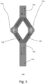
- Fig. 5 shows an embodiment of a turbine unit 240.
- the turbine unit includes a separate turbine 554 and a pump 556.
- the turbine unit includes separate flow paths or pipes which coupled to the penstock 230.
- the turbine unit includes a pump path 546 and a turbine path 542.
- the upper end of the penstock is coupled to the second or lower reservoir containing the lower-density fluid while the lower end of the penstock is coupled to the first or upper reservoir containing the high-density fluid, either directly or indirectly via a cavity tank.
- the upper end of the penstock is the turbine outlet 561 while the lower end of the penstock is the turbine inlet 562.
- the system is configured so that the high-density fluid does not come into contact with the turbine unit. For example, only the lower-density fluid flows through the turbine unit.
- the lower-density fluid such as water
- the turbine path upwards toward the lower reservoir, as indicated by the upward arrows. This causes the turbine to turn in the first direction, generating power.
- recharge mode the lower-density fluid is pumped downwards back towards the upper reservoir through the pump path by the pump, as indicated by the downward arrows. This causes the high-density fluid to be pushed back into the upper reservoir, recharging the system.
- the use of a high-density fluid in the system improves the power output.
- a high-density fluid such as water
- the pressure at the bottom pressurized cavity tank is cHd1 while the pressure at the turbine inlet is cHd1-chd2, where h is the difference in elevation between the cavity tank and the second (lower-density fluid) reservoir.
Landscapes
- Engineering & Computer Science (AREA)
- Chemical & Material Sciences (AREA)
- Combustion & Propulsion (AREA)
- Mechanical Engineering (AREA)
- General Engineering & Computer Science (AREA)
- Other Liquid Machine Or Engine Such As Wave Power Use (AREA)
- Hydraulic Turbines (AREA)
Claims (19)
- Système de stockage d'énergie hydraulique pompée (200, 300, 400b, 400d) comprenant :un premier réservoir (210, 410), le premier réservoir (210, 410) étant configuré pour contenir un fluide à haute densité (251, 451) et comportant un premier orifice d'écoulement de réservoir disposé au fond du premier réservoir (210, 410) ; etun deuxième réservoir (220, 420), le deuxième réservoir (220, 420) étant configuré pour contenir un fluide à densité plus basse (255, 455) dont la densité est plus basse que celle du fluide à haute densité (251, 451), et comportant un deuxième orifice d'écoulement de réservoir disposé au fond du deuxième réservoir (220, 420) ;ledit système comprenant en outre :un réservoir à cavité (270, 470) disposé à une altitude de réservoir à cavité, une première altitude du premier réservoir (210, 410) étant supérieure à l'altitude de réservoir à cavité dudit réservoir à cavité (270, 470), et une deuxième altitude du deuxième réservoir (220, 420) étant supérieure à l'altitude de réservoir à cavité dudit réservoir à cavité (270, 470), le réservoir à cavité (270, 470) étant configuré avec un orifice supérieur (272) de réservoir à cavité et un orifice inférieur (271) de réservoir à cavité, ledit orifice supérieur (272) de réservoir à cavité étant disposé au-dessus dudit orifice inférieur (271) de réservoir à cavité,une unité de turbine (240, 440) comportant une turbine (354, 554) et une pompe (356, 556), ladite unité de turbine (240, 440) comportant un premier orifice d'écoulement d'unité de turbine et un deuxième orifice d'écoulement d'unité de turbine, ledit deuxième orifice d'écoulement d'unité de turbine étant connecté audit deuxième orifice d'écoulement de réservoir ; etune conduite forcée (230, 430), ladite conduite forcée comportant un premier tronçon (230a, 430a) de la conduite forcée connecté audit premier orifice d'écoulement de réservoir et audit orifice inférieur (271) de réservoir à cavité, un port le plus bas du premier tronçon (230a, 430a) de la conduite forcée étant au-dessous dudit réservoir à cavité (270, 470), etun deuxième tronçon (230b, 430b) de la conduite forcée connecté audit orifice supérieur (272) de réservoir à cavité et au premier orifice d'écoulement d'unité de turbine ;caractérisé en ce queen mode de production d'électricité, le fluide à haute densité (251, 451) est configuré pour s'écouler à travers la conduite forcée (230, 430) et vers et à travers ledit réservoir à cavité (270, 470) et vers le deuxième réservoir (220, 420), forçant le fluide à densité plus basse (255, 455) à s'écouler à travers la turbine (354, 554) et dans le deuxième réservoir (220, 420), le fluide à densité plus basse (255, 455) est destiné à tourner ladite unité de turbine (240, 440) dans une première direction pour produire de l'électricité, eten mode de recharge, ladite unité de turbine (240, 440) est destinée à pomper le fluide à densité plus basse (255, 455) depuis le deuxième réservoir (220, 420) à travers la conduite forcée (230, 430) vers le premier réservoir (210, 410), forçant le fluide à haute densité (251, 451) à revenir dans le premier réservoir (210, 410) ; etle fluide à densité plus basse (255, 455) et le fluide à haute densité (251, 451) étant configurés pour empêcher le fluide à haute densité (251, 451) de passer à travers ladite unité de turbine (240, 440).
- Système selon la revendication 1, dans lequel la première altitude du premier réservoir (210, 410) est supérieure à une deuxième altitude du deuxième réservoir (220, 420).
- Système selon la revendication 1, dans lequel la première altitude du premier réservoir (210, 410) et une deuxième altitude du deuxième réservoir (220, 420) sont à peu près la même altitude.
- Système selon la revendication 1, dans lequel les premier (210, 410) et deuxième (220, 420) réservoirs comprennent des réservoirs atmosphériques cylindriques.
- Système selon la revendication 1, dans lequel ledit réservoir à cavité (270, 470) comprend un réservoir à cavité sphérique à haute pression.
- Système selon la revendication 1, dans lequel le fluide à haute densité (251, 451) comprend une boue comportant des particules.
- Système selon la revendication 1, dans lequel le fluide à densité plus basse (255, 455) comprend l'eau.
- Système selon la revendication 1, dans lequel la densité du fluide à haute densité (251, 451) est au moins 3 fois supérieur à celle du fluide à densité plus basse (255, 455).
- Système selon la revendication 6, dans lequel la boue comprend des particules d'oxyde métallique.
- Système selon la revendication 6, dans lequel la boue comprend des particules de magnétite pour former une boue de magnétite.
- Système selon la revendication 9, dans lequel :la boue comprend 50 - 85% de particules ; etla taille des particules est comprise dans la plage de quelques microns à plusieurs centaines de microns.
- Procédé de production d'électricité à partir d'un système de stockage d'énergie hydraulique pompée (200, 300, 400b, 400d) comprenant :fournir un premier réservoir (210, 410) contenant un fluide à haute densité (251, 451), le premier réservoir (210, 410) comportant un premier orifice d'écoulement de réservoir disposé au fond du premier réservoir (210, 410) ; etfournir un deuxième réservoir (220, 420) contenant un fluide à densité plus basse (255, 455) dont la densité est plus basse que celle du fluide à haute densité (251, 451), le deuxième réservoir (220, 420) comportant un deuxième orifice d'écoulement de réservoir disposé au fond du deuxième réservoir (220, 420) ;ledit procédé comprenant en outrefournir un réservoir à cavité (270, 470) disposé à une altitude de réservoir à cavité qui est inférieure à une première altitude de réservoir du premier réservoir (210, 410) et une deuxième altitude de réservoir du deuxième réservoir (220, 420), le réservoir à cavité (270, 470) étant configuré avec un orifice supérieur (272) de réservoir à cavité et un orifice inférieur (271) de réservoir à cavité, ledit orifice supérieur (272) de réservoir à cavité étant disposé au-dessus dudit orifice inférieur (271) de réservoir à cavité,fournir une unité de turbine (240, 440) comportant une turbine (354, 554) et une pompe (356, 556), ladite unité de turbine (240, 440) comportant un premier orifice d'écoulement d'unité de turbine et un deuxième orifice d'écoulement d'unité de turbine, ledit deuxième orifice d'écoulement d'unité de turbine étant connecté audit deuxième orifice d'écoulement de réservoir ; etfournir une conduite forcée (230, 430), ladite conduite forcée (230, 430) comportant un premier tronçon (230a, 430a) de la conduite forcée connecté audit premier orifice d'écoulement de réservoir et audit orifice inférieur (271) de réservoir à cavité, un port le plus bas du premier tronçon (230a, 430a) de la conduite forcée étant au-dessous dudit réservoir à cavité (270, 470), etun deuxième tronçon (230b, 430b) de la conduite forcée connecté audit orifice supérieur (272) de réservoir à cavité et au premier orifice d'écoulement d'unité de turbine ;en mode de production d'électricité, faire écouler le fluide à haute densité (251, 451) depuis le premier réservoir (210, 410) à travers la conduite forcée (230, 430) et vers et à travers ledit réservoir à cavité (270, 470) et vers le deuxième réservoir (220, 420), pour forcer le fluide à densité plus basse (255, 455) à s'écouler à travers la turbine (354, 554) et dans le deuxième réservoir (220, 420), ce qui fait tourner la turbine (354, 554) dans une première direction pour produire de l'électricité,caractérisé en ce que le procédé comprenden mode de recharge, pomper, par ladite unité de turbine (240, 440), le fluide à densité plus basse (255, 455) depuis le deuxième réservoir (220, 420) à travers la conduite forcée (230, 430) vers le premier réservoir (210, 410) pour forcer le fluide à haute densité (251, 451) dans le premier réservoir (210, 410) afin de recharger le système (200, 300, 400b, 400d) ; etlors de la circulation du fluide à densité plus basse (255, 455) et du fluide à haute densité (251, 451) dans le système (200, 300, 400b, 400d), le fluide à haute densité (251, 451) est configuré pour éviter de passer à travers ladite unité de turbine (240, 440).
- Procédé selon la revendication 12, dans lequel la densité du fluide à haute densité (251, 451) est au moins 3 fois supérieur à celle du fluide à densité plus basse (255, 455).
- Procédé selon la revendication 12, dans lequel la première altitude de réservoir du premier réservoir (210, 410) et est supérieure à la deuxième altitude du deuxième réservoir (220, 420).
- Procédé selon la revendication 12, dans lequel la première altitude de réservoir du premier réservoir (210, 410) est à peu près la même altitude que la deuxième altitude de réservoir du deuxième réservoir (220, 420).
- Procédé selon la revendication 12, dans lequel la deuxième altitude de réservoir du deuxième réservoir (220, 420) est située à proximité de l'altitude de réservoir à cavité.
- Système selon la revendication 1, dans lequel la deuxième altitude de réservoir du deuxième réservoir (220, 420) est située à proximité de l'altitude de réservoir à cavité.
- Système selon la revendication 1, dans lequel ladite unité de turbine (240, 440) comprend une turbine-pompe combinée.
- Système selon la revendication 1, dans lequel ladite unité de turbine (240, 440) comprend une turbine (354, 554) distincte et une pompe (356, 556).
Applications Claiming Priority (5)
| Application Number | Priority Date | Filing Date | Title |
|---|---|---|---|
| US201862657941P | 2018-04-16 | 2018-04-16 | |
| US201862672566P | 2018-05-16 | 2018-05-16 | |
| US201862680597P | 2018-06-05 | 2018-06-05 | |
| US201862747678P | 2018-10-19 | 2018-10-19 | |
| PCT/IB2019/053055 WO2019202456A1 (fr) | 2018-04-16 | 2019-04-13 | Système et procédé de stockage d'énergie hydraulique pompée |
Publications (3)
| Publication Number | Publication Date |
|---|---|
| EP3768967A1 EP3768967A1 (fr) | 2021-01-27 |
| EP3768967C0 EP3768967C0 (fr) | 2024-05-29 |
| EP3768967B1 true EP3768967B1 (fr) | 2024-05-29 |
Family
ID=66641184
Family Applications (1)
| Application Number | Title | Priority Date | Filing Date |
|---|---|---|---|
| EP19726146.4A Active EP3768967B1 (fr) | 2018-04-16 | 2019-04-13 | Système et procédé de stockage d'énergie hydraulique pompée |
Country Status (11)
| Country | Link |
|---|---|
| US (1) | US11365713B2 (fr) |
| EP (1) | EP3768967B1 (fr) |
| JP (1) | JP7421814B2 (fr) |
| KR (1) | KR102663650B1 (fr) |
| CN (1) | CN112119213B (fr) |
| AU (1) | AU2019254045B2 (fr) |
| ES (1) | ES2989873T3 (fr) |
| MX (1) | MX2020010958A (fr) |
| PL (1) | PL3768967T3 (fr) |
| SG (1) | SG11202010032VA (fr) |
| WO (1) | WO2019202456A1 (fr) |
Families Citing this family (8)
| Publication number | Priority date | Publication date | Assignee | Title |
|---|---|---|---|---|
| IL299690A (en) * | 2020-07-07 | 2023-03-01 | Edward VON BARGEN | Clean energy power station FFWN |
| US12535046B2 (en) * | 2020-07-17 | 2026-01-27 | Innovator Energy Llc | Fluid displacement energy storage systems and processes to enable pressure equilibrized subsea tank |
| AU2021308651A1 (en) * | 2020-07-17 | 2023-02-16 | Innovator Energy, LLC | Flow density fluid displacement to store or generate power |
| CN113404634A (zh) * | 2021-06-15 | 2021-09-17 | 五邑大学 | 基于地下坑道群的抽水蓄能电站 |
| WO2023097410A1 (fr) | 2021-11-30 | 2023-06-08 | 陆继荣 | Système de production d'énergie sous-marine mobile de navire transocéanique |
| GB2600262B (en) | 2021-12-01 | 2022-10-26 | Rheenergise Ltd | Improvements relating to energy storage |
| WO2025179151A1 (fr) * | 2024-02-23 | 2025-08-28 | Innovator Energy Llc | Systèmes et procédés de stockage d'énergie de déplacement de fluide pour permettre un réservoir sous-marin à pression équilibrée |
| US20250343465A1 (en) * | 2024-05-01 | 2025-11-06 | Dennis C PARKER | Energy storage system for use with renewable energy sources |
Family Cites Families (12)
| Publication number | Priority date | Publication date | Assignee | Title |
|---|---|---|---|---|
| DE3664227D1 (en) * | 1985-02-15 | 1989-08-10 | Shell Int Research | Energy storage and recovery |
| ATE47467T1 (de) * | 1985-03-28 | 1989-11-15 | Shell Int Research | Energieaufschlag und rueckgewinnung. |
| EP0212692B1 (fr) * | 1985-08-06 | 1989-12-20 | Shell Internationale Researchmaatschappij B.V. | Système de stockage et de récupération d'énergie |
| GB9109325D0 (en) * | 1991-04-30 | 1991-06-19 | Kenny Alan D | Apparatus for providing motive power |
| JP2000352371A (ja) * | 1999-06-08 | 2000-12-19 | Mitsubishi Heavy Ind Ltd | 圧縮空気貯蔵複合発電システム |
| CN102261299A (zh) * | 2010-05-24 | 2011-11-30 | 陈汉保 | 一种利用地下矿洞进行蓄能发电的方法 |
| DE102011117785A1 (de) * | 2011-11-05 | 2013-05-08 | Nasser Berg Energie Gmbh | Verfahren zu Energiespeicherung in unterirdischen Hohlräumen, sog. Kavernenspeicherwasserkraftwerk |
| GB2499007A (en) * | 2012-02-02 | 2013-08-07 | Impressive Engineering Ltd | Underground energy storage well |
| GB2511285B (en) * | 2012-12-22 | 2019-05-01 | John Heppenstall Richard | A novel pumped storage hydroelectric construction method |
| IL230858B (en) * | 2014-02-06 | 2018-11-29 | Broshy Yuval | System and method for high capacity pumped energy storage |
| IL232127A0 (en) * | 2014-04-13 | 2014-08-31 | Yuval Broshy | System and method for high capacity pumped energy storage with two fluids |
| CN106677969A (zh) * | 2017-02-23 | 2017-05-17 | 王政玉 | 一种储能装置 |
-
2019
- 2019-04-13 WO PCT/IB2019/053055 patent/WO2019202456A1/fr not_active Ceased
- 2019-04-13 ES ES19726146T patent/ES2989873T3/es active Active
- 2019-04-13 SG SG11202010032VA patent/SG11202010032VA/en unknown
- 2019-04-13 EP EP19726146.4A patent/EP3768967B1/fr active Active
- 2019-04-13 MX MX2020010958A patent/MX2020010958A/es unknown
- 2019-04-13 AU AU2019254045A patent/AU2019254045B2/en active Active
- 2019-04-13 JP JP2021506081A patent/JP7421814B2/ja active Active
- 2019-04-13 PL PL19726146.4T patent/PL3768967T3/pl unknown
- 2019-04-13 CN CN201980025930.3A patent/CN112119213B/zh active Active
- 2019-04-13 US US17/068,801 patent/US11365713B2/en active Active
- 2019-04-13 KR KR1020207032967A patent/KR102663650B1/ko active Active
Also Published As
| Publication number | Publication date |
|---|---|
| WO2019202456A4 (fr) | 2019-12-12 |
| CN112119213B (zh) | 2022-11-04 |
| AU2019254045B2 (en) | 2024-04-04 |
| PL3768967T3 (pl) | 2024-12-23 |
| ES2989873T3 (es) | 2024-11-28 |
| SG11202010032VA (en) | 2020-11-27 |
| US11365713B2 (en) | 2022-06-21 |
| MX2020010958A (es) | 2020-11-09 |
| EP3768967C0 (fr) | 2024-05-29 |
| KR102663650B1 (ko) | 2024-05-08 |
| US20210363959A1 (en) | 2021-11-25 |
| AU2019254045A1 (en) | 2020-12-03 |
| JP2021522447A (ja) | 2021-08-30 |
| WO2019202456A1 (fr) | 2019-10-24 |
| KR20210008842A (ko) | 2021-01-25 |
| EP3768967A1 (fr) | 2021-01-27 |
| CN112119213A (zh) | 2020-12-22 |
| JP7421814B2 (ja) | 2024-01-25 |
Similar Documents
| Publication | Publication Date | Title |
|---|---|---|
| AU2019254045B2 (en) | Pumped hydro energy storage system and method | |
| Hunt et al. | Buoyancy Energy Storage Technology: An energy storage solution for islands, coastal regions, offshore wind power and hydrogen compression | |
| AU2008305434B2 (en) | Hydroelectric pumped-storage | |
| US9617970B2 (en) | Pumped-storage power plant | |
| US9617969B2 (en) | Hydraulic energy store | |
| US11772754B2 (en) | Hydroelectricity production facility using changes in water column density to induce vertical flow | |
| US8456031B1 (en) | Underwater pumped-hydro energy storage | |
| US20200378354A1 (en) | Apparatus and Method for Generation of Electricity with Pressurized Water and Air Flow Media | |
| WO2011112561A2 (fr) | Système offshore permettant de récolter et de stocker de l'énergie et de générer de l'électricité | |
| CN101392638A (zh) | 一种天然气水合物固态开采实验模拟装置 | |
| US12215661B2 (en) | Pumped hydro energy storage system and method, including fire extinguishing features | |
| JP2017078354A (ja) | 発電システム | |
| CN105020088A (zh) | 大气压力和地心引力发电装置 | |
| EP4649235A1 (fr) | Stockage d'énergie potentielle submersible et puissance | |
| US8987932B2 (en) | Deep water hydro-electric power system | |
| ES2798158A1 (es) | Sistema y metodo de generacion y almacenamiento de energia | |
| JP2015183643A (ja) | 発電装置、および送電システム | |
| US11894685B1 (en) | Systems and processes for pipeline transport of water using micro hydroelectric turbines to reduce electricity drawn from third-party electrical power grids | |
| Hunt et al. | Buoyancy Energy Storage Technology: An energy storage solution for islands, coastal regions, offshore wind power and hydrogen compression | |
| WO2025147726A1 (fr) | Système d'énergie hydrostatique-gravité (énergie hydrostatique et gravité) | |
| GB2586336A (en) | A boost pumped hydro energy storage system | |
| CN106437635A (zh) | 水下抽油机装置 | |
| IE85908B1 (en) | Large scale water pumping system (energy and fuel free) |
Legal Events
| Date | Code | Title | Description |
|---|---|---|---|
| STAA | Information on the status of an ep patent application or granted ep patent |
Free format text: STATUS: UNKNOWN |
|
| STAA | Information on the status of an ep patent application or granted ep patent |
Free format text: STATUS: THE INTERNATIONAL PUBLICATION HAS BEEN MADE |
|
| PUAI | Public reference made under article 153(3) epc to a published international application that has entered the european phase |
Free format text: ORIGINAL CODE: 0009012 |
|
| STAA | Information on the status of an ep patent application or granted ep patent |
Free format text: STATUS: REQUEST FOR EXAMINATION WAS MADE |
|
| 17P | Request for examination filed |
Effective date: 20201022 |
|
| AK | Designated contracting states |
Kind code of ref document: A1 Designated state(s): AL AT BE BG CH CY CZ DE DK EE ES FI FR GB GR HR HU IE IS IT LI LT LU LV MC MK MT NL NO PL PT RO RS SE SI SK SM TR |
|
| AX | Request for extension of the european patent |
Extension state: BA ME |
|
| DAV | Request for validation of the european patent (deleted) | ||
| DAX | Request for extension of the european patent (deleted) | ||
| STAA | Information on the status of an ep patent application or granted ep patent |
Free format text: STATUS: EXAMINATION IS IN PROGRESS |
|
| 17Q | First examination report despatched |
Effective date: 20210826 |
|
| GRAP | Despatch of communication of intention to grant a patent |
Free format text: ORIGINAL CODE: EPIDOSNIGR1 |
|
| STAA | Information on the status of an ep patent application or granted ep patent |
Free format text: STATUS: GRANT OF PATENT IS INTENDED |
|
| INTG | Intention to grant announced |
Effective date: 20231206 |
|
| GRAS | Grant fee paid |
Free format text: ORIGINAL CODE: EPIDOSNIGR3 |
|
| GRAA | (expected) grant |
Free format text: ORIGINAL CODE: 0009210 |
|
| STAA | Information on the status of an ep patent application or granted ep patent |
Free format text: STATUS: THE PATENT HAS BEEN GRANTED |
|
| AK | Designated contracting states |
Kind code of ref document: B1 Designated state(s): AL AT BE BG CH CY CZ DE DK EE ES FI FR GB GR HR HU IE IS IT LI LT LU LV MC MK MT NL NO PL PT RO RS SE SI SK SM TR |
|
| REG | Reference to a national code |
Ref country code: CH Ref legal event code: EP |
|
| REG | Reference to a national code |
Ref country code: IE Ref legal event code: FG4D |
|
| REG | Reference to a national code |
Ref country code: DE Ref legal event code: R096 Ref document number: 602019052912 Country of ref document: DE |
|
| U01 | Request for unitary effect filed |
Effective date: 20240628 |
|
| U07 | Unitary effect registered |
Designated state(s): AT BE BG DE DK EE FI FR IT LT LU LV MT NL PT SE SI Effective date: 20240708 |
|
| PG25 | Lapsed in a contracting state [announced via postgrant information from national office to epo] |
Ref country code: IS Free format text: LAPSE BECAUSE OF FAILURE TO SUBMIT A TRANSLATION OF THE DESCRIPTION OR TO PAY THE FEE WITHIN THE PRESCRIBED TIME-LIMIT Effective date: 20240929 |
|
| PG25 | Lapsed in a contracting state [announced via postgrant information from national office to epo] |
Ref country code: HR Free format text: LAPSE BECAUSE OF FAILURE TO SUBMIT A TRANSLATION OF THE DESCRIPTION OR TO PAY THE FEE WITHIN THE PRESCRIBED TIME-LIMIT Effective date: 20240529 |
|
| PG25 | Lapsed in a contracting state [announced via postgrant information from national office to epo] |
Ref country code: GR Free format text: LAPSE BECAUSE OF FAILURE TO SUBMIT A TRANSLATION OF THE DESCRIPTION OR TO PAY THE FEE WITHIN THE PRESCRIBED TIME-LIMIT Effective date: 20240830 |
|
| PG25 | Lapsed in a contracting state [announced via postgrant information from national office to epo] |
Ref country code: NO Free format text: LAPSE BECAUSE OF FAILURE TO SUBMIT A TRANSLATION OF THE DESCRIPTION OR TO PAY THE FEE WITHIN THE PRESCRIBED TIME-LIMIT Effective date: 20240829 Ref country code: IS Free format text: LAPSE BECAUSE OF FAILURE TO SUBMIT A TRANSLATION OF THE DESCRIPTION OR TO PAY THE FEE WITHIN THE PRESCRIBED TIME-LIMIT Effective date: 20240929 Ref country code: HR Free format text: LAPSE BECAUSE OF FAILURE TO SUBMIT A TRANSLATION OF THE DESCRIPTION OR TO PAY THE FEE WITHIN THE PRESCRIBED TIME-LIMIT Effective date: 20240529 Ref country code: GR Free format text: LAPSE BECAUSE OF FAILURE TO SUBMIT A TRANSLATION OF THE DESCRIPTION OR TO PAY THE FEE WITHIN THE PRESCRIBED TIME-LIMIT Effective date: 20240830 Ref country code: RS Free format text: LAPSE BECAUSE OF FAILURE TO SUBMIT A TRANSLATION OF THE DESCRIPTION OR TO PAY THE FEE WITHIN THE PRESCRIBED TIME-LIMIT Effective date: 20240829 |
|
| REG | Reference to a national code |
Ref country code: ES Ref legal event code: FG2A Ref document number: 2989873 Country of ref document: ES Kind code of ref document: T3 Effective date: 20241128 |
|
| PG25 | Lapsed in a contracting state [announced via postgrant information from national office to epo] |
Ref country code: CZ Free format text: LAPSE BECAUSE OF FAILURE TO SUBMIT A TRANSLATION OF THE DESCRIPTION OR TO PAY THE FEE WITHIN THE PRESCRIBED TIME-LIMIT Effective date: 20240529 |
|
| PG25 | Lapsed in a contracting state [announced via postgrant information from national office to epo] |
Ref country code: SK Free format text: LAPSE BECAUSE OF FAILURE TO SUBMIT A TRANSLATION OF THE DESCRIPTION OR TO PAY THE FEE WITHIN THE PRESCRIBED TIME-LIMIT Effective date: 20240529 Ref country code: RO Free format text: LAPSE BECAUSE OF FAILURE TO SUBMIT A TRANSLATION OF THE DESCRIPTION OR TO PAY THE FEE WITHIN THE PRESCRIBED TIME-LIMIT Effective date: 20240529 |
|
| PG25 | Lapsed in a contracting state [announced via postgrant information from national office to epo] |
Ref country code: SM Free format text: LAPSE BECAUSE OF FAILURE TO SUBMIT A TRANSLATION OF THE DESCRIPTION OR TO PAY THE FEE WITHIN THE PRESCRIBED TIME-LIMIT Effective date: 20240529 |
|
| PG25 | Lapsed in a contracting state [announced via postgrant information from national office to epo] |
Ref country code: SM Free format text: LAPSE BECAUSE OF FAILURE TO SUBMIT A TRANSLATION OF THE DESCRIPTION OR TO PAY THE FEE WITHIN THE PRESCRIBED TIME-LIMIT Effective date: 20240529 Ref country code: SK Free format text: LAPSE BECAUSE OF FAILURE TO SUBMIT A TRANSLATION OF THE DESCRIPTION OR TO PAY THE FEE WITHIN THE PRESCRIBED TIME-LIMIT Effective date: 20240529 Ref country code: RO Free format text: LAPSE BECAUSE OF FAILURE TO SUBMIT A TRANSLATION OF THE DESCRIPTION OR TO PAY THE FEE WITHIN THE PRESCRIBED TIME-LIMIT Effective date: 20240529 Ref country code: CZ Free format text: LAPSE BECAUSE OF FAILURE TO SUBMIT A TRANSLATION OF THE DESCRIPTION OR TO PAY THE FEE WITHIN THE PRESCRIBED TIME-LIMIT Effective date: 20240529 |
|
| PLBE | No opposition filed within time limit |
Free format text: ORIGINAL CODE: 0009261 |
|
| STAA | Information on the status of an ep patent application or granted ep patent |
Free format text: STATUS: NO OPPOSITION FILED WITHIN TIME LIMIT |
|
| 26N | No opposition filed |
Effective date: 20250303 |
|
| U20 | Renewal fee for the european patent with unitary effect paid |
Year of fee payment: 7 Effective date: 20250417 |
|
| PGFP | Annual fee paid to national office [announced via postgrant information from national office to epo] |
Ref country code: PL Payment date: 20250410 Year of fee payment: 7 |
|
| PGFP | Annual fee paid to national office [announced via postgrant information from national office to epo] |
Ref country code: GB Payment date: 20250425 Year of fee payment: 7 Ref country code: ES Payment date: 20250512 Year of fee payment: 7 |
|
| REG | Reference to a national code |
Ref country code: CH Ref legal event code: H13 Free format text: ST27 STATUS EVENT CODE: U-0-0-H10-H13 (AS PROVIDED BY THE NATIONAL OFFICE) Effective date: 20251125 |
|
| PG25 | Lapsed in a contracting state [announced via postgrant information from national office to epo] |
Ref country code: MC Free format text: LAPSE BECAUSE OF FAILURE TO SUBMIT A TRANSLATION OF THE DESCRIPTION OR TO PAY THE FEE WITHIN THE PRESCRIBED TIME-LIMIT Effective date: 20240529 |
|
| PG25 | Lapsed in a contracting state [announced via postgrant information from national office to epo] |
Ref country code: CH Free format text: LAPSE BECAUSE OF NON-PAYMENT OF DUE FEES Effective date: 20250430 |
|
| PG25 | Lapsed in a contracting state [announced via postgrant information from national office to epo] |
Ref country code: IE Free format text: LAPSE BECAUSE OF NON-PAYMENT OF DUE FEES Effective date: 20250413 |