EP3769324B1 - Noyaux de transformateur et procédés d'assemblage de ceux-ci pour une efficacité élevée et des performances anti-corrosion élevées - Google Patents
Noyaux de transformateur et procédés d'assemblage de ceux-ci pour une efficacité élevée et des performances anti-corrosion élevées Download PDFInfo
- Publication number
- EP3769324B1 EP3769324B1 EP18916458.5A EP18916458A EP3769324B1 EP 3769324 B1 EP3769324 B1 EP 3769324B1 EP 18916458 A EP18916458 A EP 18916458A EP 3769324 B1 EP3769324 B1 EP 3769324B1
- Authority
- EP
- European Patent Office
- Prior art keywords
- laminations
- mean length
- sub
- lamination
- leg
- Prior art date
- Legal status (The legal status is an assumption and is not a legal conclusion. Google has not performed a legal analysis and makes no representation as to the accuracy of the status listed.)
- Active
Links
Images


Classifications
-
- H—ELECTRICITY
- H01—ELECTRIC ELEMENTS
- H01F—MAGNETS; INDUCTANCES; TRANSFORMERS; SELECTION OF MATERIALS FOR THEIR MAGNETIC PROPERTIES
- H01F27/00—Details of transformers or inductances, in general
- H01F27/24—Magnetic cores
- H01F27/26—Fastening parts of the core together; Fastening or mounting the core on casing or support
- H01F27/263—Fastening parts of the core together
-
- H—ELECTRICITY
- H01—ELECTRIC ELEMENTS
- H01F—MAGNETS; INDUCTANCES; TRANSFORMERS; SELECTION OF MATERIALS FOR THEIR MAGNETIC PROPERTIES
- H01F27/00—Details of transformers or inductances, in general
- H01F27/24—Magnetic cores
- H01F27/245—Magnetic cores made from sheets, e.g. grain-oriented
-
- H—ELECTRICITY
- H01—ELECTRIC ELEMENTS
- H01F—MAGNETS; INDUCTANCES; TRANSFORMERS; SELECTION OF MATERIALS FOR THEIR MAGNETIC PROPERTIES
- H01F27/00—Details of transformers or inductances, in general
- H01F27/28—Coils; Windings; Conductive connections
-
- H—ELECTRICITY
- H01—ELECTRIC ELEMENTS
- H01F—MAGNETS; INDUCTANCES; TRANSFORMERS; SELECTION OF MATERIALS FOR THEIR MAGNETIC PROPERTIES
- H01F41/00—Apparatus or processes specially adapted for manufacturing or assembling magnets, inductances or transformers; Apparatus or processes specially adapted for manufacturing materials characterised by their magnetic properties
- H01F41/02—Apparatus or processes specially adapted for manufacturing or assembling magnets, inductances or transformers; Apparatus or processes specially adapted for manufacturing materials characterised by their magnetic properties for manufacturing cores, coils, or magnets
- H01F41/0206—Manufacturing of magnetic cores by mechanical means
- H01F41/0233—Manufacturing of magnetic circuits made from sheets
Definitions
- This disclosure relates to transformers used for electric power distribution and, more particularly, to transformer cores and laminated construction assembly methods thereof.
- Transformers are used to increase or decrease voltage levels during electrical power distribution.
- a transformer may be used to raise the voltage of the power being transmitted, which reduces the current.
- a reduced current reduces resistive power losses that occur in the electrical cables used to transmit the power.
- another transformer may be used to reduce the voltage, which increases the current, to a level specified by the end user.
- Such transformers may be located in, e.g., an underground power distribution network common in some cities. These transformers may be in contact with and need to be protected from harsh environments that may include exposure to water, humidity, pollution, and the like. In particular, the transformer core needs to be protected in order to maintain the electromagnetic performance of the transformer. A laminated core construction of such transformers may, however, be prone to corrosion.
- US 3,614,695 A describes an electrical inductive apparatus including a magnetic core constructed of stacked-magnetic laminations arranged to provide a plurality of spaced leg portions, the adjacent ends of which are joined by first and second yoke portions.
- US 4,283,842 A describes a magnetic core for an electrical inductive apparatus, and a method of constructing such an electrical apparatus. Accordingly, improved laminated core construction and assembly methods thereof for submersible and other dry-type transformers are desired.
- a transformer core includes a plurality of laminations stacked together having a step-lap sequence of laminations.
- the step-lap sequence has a first sub-plurality of the laminations each having a first mean length and aligned longitudinally with and stacked directly to each other.
- the step-lap sequence also has a second sub-plurality of the laminations each having a second mean length and aligned longitudinally with and stacked directly to each other, wherein the second sub-plurality of the laminations is stacked directly to the first sub-plurality of the laminations.
- the first sub-plurality of the laminations or the second sub-plurality of the laminations has at least four laminations, and the first mean length is different than the second mean length.
- the step-lap sequence comprises at least 20 laminations that include at least four identical longitudinally and transversely aligned laminations stacked directly to each other, each having a same shortest mean length of the step-lap sequence.
- a transformer includes a transformer core having a plurality of legs, a lower yoke, and an upper yoke, wherein each leg is interconnected to the lower yoke and to the upper yoke via a step-lap joint.
- the transformer also includes a plurality of coils, each coil surrounding a respective leg.
- Each leg, the lower yoke, and the upper yoke includes a respective plurality of laminations stacked together having a step-lap sequence of laminations that includes a first sub-plurality of the laminations each having a first mean length and aligned longitudinally with and stacked directly to each other, and a second sub-plurality of the laminations each having a second mean length and aligned longitudinally with and stacked directly to each other, wherein the second sub-plurality of the laminations is stacked directly to the first sub-plurality of the laminations.
- the first sub-plurality of the laminations or the second sub-plurality of the laminations has at least four laminations, and the first mean length is different than the second mean length.
- a method of constructing a transformer core includes receiving a plurality of laminations, stacking directly to each other a first sub-plurality of laminations aligned longitudinally with each other and each having a first mean length, stacking directly to each other a second sub-plurality of laminations aligned longitudinally with each other and each having a second mean length, and stacking the second sub-plurality of the laminations directly to the first sub-plurality of the laminations.
- the first sub-plurality of the laminations or the second sub-plurality of the laminations has at least four laminations, and the first mean length is different than the second mean length.
- the step-lap sequence comprises at least 20 laminations that include at least four identical longitudinally and transversely aligned laminations stacked directly to each other, each having a same shortest mean length of the step-lap sequence.
- Submersible dry-type transformers are configured to operate in open air, underground, partially submerged, or completely submerged, and are often used in underground power distribution networks. Such transformers, and particularly their transformer core, may thus be exposed to harsh environments that may include contact with water, pollutants, humidity, etc.
- Submersible dry-type transformers are often configured to deliver multiple phases of electrical power, such as 2-phase or 3-phase, and may have a power rating in the range of 500 kVA to about 2000 kVA and a voltage rating of 15-kV or 25-kV.
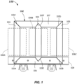
- FIG. 1 illustrates a three-phase transformer 100, which may be a submersible dry-type transformer, in accordance with one or more embodiments which are not part of the invention.
- transformer 100 may have a different number of phases (e.g., two phases) and may also be single phase (which may be 1 phase + 1 phase, 1 phase + neutral, or 1 phase + ground).
- Transformer 100 may include a transformer (magnetic) core 102 through which a magnetic flux flows.
- Transformer core 102 may be painted or otherwise coated with an anti-corrosive paint or sealer to protect transformer core 102 from its environment.
- Transformer core 102 may be a formed, e.g., by having a first leg 103, a second leg 104, and a third leg 105 interconnected to a lower yoke 106 and an upper yoke 107.
- Other embodiments which are not part of the invention may have, e.g., two, four, or five legs.
- Each leg 103-105 may be surrounded by a respective voltage transformer coil 108A-C (shown in phantom), each of which may also be referred to as a winding.
- transformer coils 108A-C may each include a high voltage coil and an inner low voltage coil, which may be concentric.
- the inner low voltage coil may be electrically isolated from transformer core 102 and from the high voltage coil.
- the lower yoke 106 may be clamped to the bottom end of each of legs 103-105 via a clamp 109 (shown in phantom), which may be, e.g., a pair of steel beams bolted together with the lower yoke 106 and legs 103-105 located there between.
- a transformer e.g., an upper clamp, coil housings, shielding, insulation, voltage terminals, grounding connections, cables creating delta or wye transformer configurations, etc.
- FIG. 1 for clarity.
- Transformer core 102 which is not part of the invention may have a laminated construction. That is, transformer core 102 may be made from thousands of thin electrical steel laminations stacked together. Electrical steel is a special type of steel fabricated to produce specific magnetic properties. In some embodiments, which are not part of the invention, each lamination may range in thickness from 0.2 mm to 0.5 mm. Laminations may have other thicknesses. Each of lower yoke 106, upper yoke 107, and legs 103-105 may be formed from a respective stack of laminations and then joined together to form lamination layers of transformer core 102. The longitudinal ends of each leg and the upper and lower yokes may have a diagonal cut as shown in FIG. 1 .
- each longitudinal end of legs 103 and 105 may have a 45 degree diagonal cut, while each longitudinal end of leg 104 may have a centered V-shape cut (in a vertical cutting and assembly process).
- leg 104 may have an offset V-shape cut (in a horizontal cutting and assembly process), as described below in connection with FIG. 5A .
- Each longitudinal end of lower yoke 106 and upper yoke 107 may also have a 45 degree diagonal cut (to complement the diagonal cuts of legs 103 and 105).
- Lower yoke 106 and upper yoke 107 may also have a V-shaped notch cut into an inside longitudinal edge (to complement the V-shaped longitudinal end of leg 104).
- Transformer core 102 may further be assembled, in some embodiments, which are not part of the invention, by abutting one longitudinal end of each leg 103-105 to lower yoke 106 to form diagonal joints 110A and 110B and V-shaped joint 110E between the laminations. That E-shaped assembly (the E being on its back) may be clamped together with clamp 109, and may be painted or otherwise protected with an anti-corrosive paint, coating, or sealer. Upper yoke 107 may then be abutted to the other longitudinal end of each leg 103-105 to form diagonal joints 110C and 110D and V-shaped joint 110F between the laminations. The upper portion of the transformer core assembly may then be clamped and protected with the anti-corrosive paint, coating, or sealer.
- each lamination of the leg and yoke at joints 110A-F may be a "step-lap" joint.
- a step-lap joint is created by staggering or offsetting the location of the joint in one or more succeeding lamination layers relative to one another.
- FIG. 2 illustrates a transformer core corner 200 of an upper yoke 207 interconnected with a leg 205 using a known step-lap profile 300, shown in FIG. 3 .
- Step-lap profile 300 has three steps, each step having a respective single lamination 301-1, 301-2, and 301-3. (although some known step-lap profiles may have two laminations per step (e.g., two laminations 301-1, two laminations 301-2, etc.), they may have the same disadvantages as step-lap profile 300, described below). The three steps may be repeated many times to form a transformer core leg or yoke having a desired thickness or number of laminations.
- Step-lap profile 300 may form staggered step-lap joints 210A, 210B, and 210C as shown in FIG. 2.
- FIGS. 2A-2C illustrate, respectively, the first three lamination layers 200-1, 200-2, and 200-3 of transformer core corner 200.
- Lamination layer 200-1 includes a yoke lamination 207-1 and a leg lamination 205-1;
- lamination layer 200-2 includes a yoke lamination 207-2 and a leg lamination 205-2;
- lamination layer 200-3 includes a yoke lamination 207-3 and a leg lamination 205-3.
- Yoke lamination 207-1 has a mean length shorter than yoke lamination 207-2, which has a mean length shorter than yoke lamination 207-3.
- leg lamination 205-1 has a mean length longer than leg lamination 205-2, which has a mean length longer than leg lamination 205-3.
- laminations 301-1, 301-2, and 301-3 of step-lap profile 300 may respectively represent yoke lamination 207-3 (the longest yoke lamination), yoke lamination 207-2, and yoke lamination 207-1 (the shortest yoke lamination), while laminations 301-1, 301-2, and 301-3 may also respectively represent leg lamination 205-1 (the longest leg lamination), leg lamination 205-2, and leg lamination 205-3 (the shortest leg lamination).
- lamination layer 200-1 has a gap 212-1 between upper yoke lamination 207-1 and leg lamination 205-1 and, as shown in FIG. 2C , lamination layer 200-3 has a gap 212-3 between upper yoke lamination 207-3 and leg lamination 205-3.
- gaps 212-1 and 212-3 also repeat creating a sudden change in surface geometry that includes very small, steep, and/or narrow "valleys" 312 in the inside corners of the yoke and leg interconnections.
- step-lap profiles with additional single lamination steps may further increase the steepness and/or narrowness of valleys 312.
- Valleys 312 are problematic because they may be difficult to fully and/or adequately protect with an anti-corrosive paint, coating, and/or sealer, thus exposing those areas to the environment. In harsh environments, as described above, significant degradation of transformer performance can occur within only months of unprotected or inadequately protected exposure.
- an improved step-lap profile and laminated construction of a transformer core may improve the corrosive resistance of the assembled transformer core by allowing an anti-corrosive paint, coating, and/or sealer (e.g., comprising silicone) to easily reach or be applied to the inside corners of transformer core yoke and leg interconnections.
- the improved step-lap profile may also reduce manufacturing complexity and cost compared to other transformer core manufacturing techniques.
- the improved step-lap profile may further improve the magnetic flux flow, reduce transformer noise and, thus, the overall performance of the transformer core.
- FIGS. 4-8 illustrate transformer core leg and yoke laminations that may be used to construct transformer core 102 (of FIG. 1 ) with step-lap joints in accordance with one or more embodiments which are not part of the invention.
- leg laminations 403 may include a first leg lamination 403-1 having a mean length L1 (all mean lengths measured along a center longitudinal axis 414); a second leg lamination 403-2 having a mean length L2, which is shorter than mean length L1; a third leg lamination 403-3 having a mean length L3, which is shorter than mean length L2; a fourth leg lamination 403-4 having a mean length L4, which is shorter than mean length L3; and a fifth leg lamination 403-5 having a mean length L5, which is shorter than mean length L4.
- Each of leg laminations 403-1, 403-2, 403-3, 403-4, and 403-5 has a same transverse width W1.
- a dimension of transverse width W1 may be determined, in part, by desired magnetic flux properties of the transformer core.
- Each of leg laminations 403-1, 403-2, 403-3, 403-4, and 403-5 has a diagonal cut at each of their longitudinal ends, which may be at an angle A1 of about 45 degrees. Other suitable angles are possible for the diagonal cuts.
- Leg laminations 403 may be used to construct, e.g., leg 103 or leg 105 of transformer core 102 (of FIG. 1 ), as described in more detail below.
- FIG. 5 illustrates leg laminations 504, which may include a first leg lamination 504-1 having a first mean length (all mean lengths measured along a center longitudinal axis 514); a second leg lamination 504-2 having a second mean length, which is shorter than the first mean length; a third leg lamination 504-3 having a third mean length, which is shorter than the second mean length; a fourth leg lamination 504-4 having a fourth mean length, which is shorter than the third mean length; and a fifth leg lamination 504-5 having a fifth mean length, which is shorter than the fourth mean length.
- Each of leg laminations 504-1, 504-2, 504-3, 504-4, and 504-5 has a same transverse width W2, which may be the same as transverse width W1.
- a dimension of transverse width W2 may be determined, in part, by desired magnetic flux properties of the transformer core.
- Each of leg laminations 504-1, 504-2, 504-3, 504-4, and 504-5 has centered V-shaped longitudinal ends (for the vertical type cut process), as shown. Other suitable shapes are possible at the longitudinal ends.
- Leg laminations 504 may be used to construct, e.g., leg 104 of transformer core 102 (of FIG. 1 ), as described in more detail below.
- FIG. 5A illustrates alternative leg laminations 504A, which may be formed by a horizontal cutting and assembly process, in accordance with one or more embodiments which are not part of the invention.
- Leg laminations 504A may include: a first leg lamination 504A-1 having a first offset V-shape at each longitudinal end (only one longitudinal end shown for each lamination); a second leg lamination 504A-2 having a second offset V-shape at each longitudinal end, the tip of the second offset V-shape positioned horizontally to the right (as shown) of the tip of the first offset V-shape; a third leg lamination 504A-3 having a third offset V-shape (which in some embodiments which are not part of the invention may be a centered V-shape) at each longitudinal end, the tip of the third offset V-shape positioned horizontally to the right (as shown) of the tip of the second offset V-shape; a fourth leg lamination 504A-4 having a fourth offset
- leg laminations 504A-1, 504A-2, 504A-3, 504A-4, and 504A-5 may be reversed from that shown (i.e., may start with leg lamination 504A-5), or may start with leg lamination 504A-3 (i.e., the middle lamination).
- Each of leg laminations 504A-1, 504A-2, 504A-3, 504A-4, and 504A-5 has a same longitudinal length measured from the tip of the V-shape at one longitudinal end to the tip of the V-shape at the other longitudinal end.
- Each of leg laminations 504A-1, 504A-2, 504A-3, 504A-4, and 504A-5 has a same transverse width W2A, which may be the same as transverse width W1 and/or W2.
- a dimension of transverse width W2A may be determined, in part, by desired magnetic flux properties of the transformer core.
- Each of the V-shaped ends of leg laminations 504A-1, 504A-2, 504A-3, 504A-4, and 504A-5 may be cut at 45 degree angles with respect to a longitudinal axis 514A. Other suitable angles are possible for the V-shaped longitudinal ends.
- Leg laminations 504A may be used to construct, e.g., leg 104 of transformer core 102 (of FIG. 1 ), as described in more detail below.
- FIG. 6 illustrates leg laminations 605, which may be identical to leg laminations 403 (which may be flipped along a vertical axis).
- Leg laminations 605 may include a first leg lamination 605-1 having a first mean length (all mean lengths measured along a center longitudinal axis 614) that may be equal to mean length L1; a second leg lamination 605-2 having a second mean length that may be equal to mean length L2, which is shorter than the first mean length; a third leg lamination 605-3 having a third mean length that may be equal to mean length L3, which is shorter than the second mean length; a fourth leg lamination 605-4 having a fourth mean length that may be equal to mean length L4, which is shorter than the third mean length; and a fifth leg lamination 605-5 having a fifth mean length that may be equal to mean length L5, which is shorter than the fourth mean length.
- Each of leg laminations 605-1, 605-2, 605-3, 605-4, and 605-5 has a same transverse width W3, which may be the same as transverse width W1 and/or W2.
- a dimension of transverse width W3 may be determined, in part, by desired magnetic flux properties of the transformer core.
- Each of leg laminations 605-1, 605-2, 605-3, 605-4, and 605-5 has a diagonal cut at each of their longitudinal ends, which may be about 45 degrees with respect to longitudinal axis 614 (i.e., same as angle A1). Other suitable angles are possible for the diagonal cuts.
- Leg laminations 605 may be used to construct, e.g., leg 103 or leg 105 of transformer core 102 (of FIG. 1 ), as described in more detail below.
- FIG. 7 illustrates upper yoke laminations 707, which may include a first yoke lamination 707-1 having a mean length Y-L1 (all mean lengths measured along a center longitudinal axis 714); a second yoke lamination 707-2 having a mean length Y-L2, which is longer than mean length Y-L1; a third yoke lamination 707-3 having a mean length Y-L3, which is longer than mean length Y-L2; a fourth yoke lamination 707-4 having a mean length Y-L4, which is longer than mean length Y-L3; and a fifth yoke lamination 707-5 having a mean length Y-L5, which is longer than mean length Y-L4.
- a first yoke lamination 707-1 having a mean length Y-L1 (all mean lengths measured along a center longitudinal axis 714);
- a second yoke lamination 707-2 having a mean length
- Each of yoke laminations 707-1, 707-2, 707-3, 707-4, and 707-5 has a same transverse width W4, which may be the same as transverse width W1, W2, and/or W3.
- a dimension of transverse width W4 may be determined, in part, by desired magnetic flux properties of the transformer core.
- Each of yoke laminations 707-1, 707-2, 707-3, 707-4, and 707-5 has a diagonal cut at each of their longitudinal ends that complements the diagonal cut at a longitudinal end of leg laminations 403 and 605. The diagonal cuts may be at angle A1, which may be about 45 degrees.
- Each of yoke laminations 707-1, 707-2, 707-3, 707-4, and 707-5 also may have a centered V-shaped notch of different size (only V-shaped notch 716-1 is labeled in FIG. 7 to maintain clarity), or each of yoke laminations 707-1, 707-2, 707-3, 707-4, and 707-5 may have an offset V-shaped notch of the same size staggered horizontally (not shown). The V-shaped notch is cut into an inside (i.e., the shorter) longitudinal edge 718, as shown.
- Each V-shaped notch is dimensioned to complement a respective V-shaped longitudinal end of leg laminations 504 or 504A in order to form a step-lap joint thereat.
- Upper yoke laminations 707 may be used to construct, e.g., lower yoke 106 or upper yoke 107 of transformer core 102 (of FIG. 1 ), as described in more detail below.
- FIG. 8 illustrates lower yoke laminations 806, which may be identical to upper yoke laminations 707 (which may be flipped along a horizontal axis).
- Lower yoke laminations 806 may include a first yoke lamination 806-1 having a first mean length (all mean lengths measured along a center longitudinal axis 814) that may be equal to mean length Y-L1; a second yoke lamination 806-2 having a second mean length that may be equal to mean length Y-L2, which is longer than the first mean length; a third yoke lamination 806-3 having a third mean length that may be equal to mean length Y-L3, which is longer than the second mean length; a fourth yoke lamination 806-4 having a fourth mean length that may be equal to mean length Y-L4, which is longer than the third mean length; and a fifth yoke lamination 806-5 having a fifth mean length that may be equal to mean length Y-L5, which is longer
- Each of yoke laminations 806-1, 806-2, 806-3, 806-4, and 806-5 has a same transverse width W5, which may be the same as transverse width W1, W2, W3, and/or W4.
- a dimension of transverse width W5 may be determined, in part, by desired magnetic flux properties of the transformer core.
- Each of yoke laminations 806-1, 806-2, 806-3, 806-4, and 806-5 has a diagonal cut at each of their longitudinal ends that complements the diagonal cut at a longitudinal end of leg laminations 403 and 605. The diagonal cuts may be about 45 degrees with respect to longitudinal axis 814 (i.e., same as angle A1).
- Each of yoke laminations 806-1, 806-2, 806-3, 806-4, and 806-5 also may have a centered V-shaped notch of different size (only V-shaped notch 816-1 is labeled in FIG. 8 to maintain clarity), or each of yoke laminations 806-1, 806-2, 806-3, 806-4, and 806-5 may have an offset V-shaped notch of the same size staggered horizontally (not shown). The V-shaped notch is cut into an inside (i.e., the shorter) longitudinal edge 818, as shown.
- Each V-shaped notch is dimensioned to complement a respective V-shaped longitudinal end of leg laminations 504 or 504A in order to form a step-lap joint thereat.
- Lower yoke laminations 806 may be used to construct, e.g., lower yoke 106 or upper yoke 107 of transformer core 102 (of FIG. 1 ), as described in more detail below.
- FIG. 9 illustrates a step-lap profile 900, which may also illustrate a partial side view of a stacked laminated construction of legs 103-105 of FIG. 1 and/or leg laminations 403, 504, and/or 605 of FIGS. 4-6 , respectively, in accordance with the invention.
- Step-lap profile 900 may be used to form step-lap joints with leg laminations 403, 504, 504A, and 605 and upper yoke laminations 707 and lower yoke laminations 806 in the assembly of transformer core 102.
- Step-lap profile 900 may have five groups 920, 921, 922, 923, and 924 of laminations, wherein each group has at least two identical longitudinally and transversely aligned laminations stacked directly to each other.
- Each group may also have a mean length different than an adjacent group to form four steps.
- group 920 may have two identical laminations 901-1 each having a same mean length different than adjacent group 921, which has two identical laminations 901-2 each having a same mean length different than the mean length of laminations 901-1.
- the size of each step may range from 3 mm to 7 mm.
- the mean length difference from one group to an adjacent group may range from 3 mm to 7 mm.
- the mean length difference between group 920 (having the longest mean length) and group 924 (having the shortest mean length) may range from 12 mm to 28 mm (i.e., separated by four steps).
- the distances between the tips of the offset V-shaped longitudinal ends of leg laminations 504A may follow the same step dimensions. That is, e.g., the distance between the tip of the first offset V-shape of leg lamination 504A-1 and the tip of the second offset V-shape of leg lamination 504A-2 may be 3 mm to 7 mm, and so on. Other embodiments may have other suitable step dimensions.
- step-lap sequence 925 has at least 20 laminations that include at least four identical longitudinally and transversely aligned laminations 901-5 stacked directly to each other, each having the same shortest mean length of step-lap sequence 925.
- Step-lap sequence 925 may also include at least four other identical longitudinally and transversely aligned laminations 901-9 stacked directly to each other, each having the longest mean length of step-lap sequence 925.
- Stacked between laminations 901-5 and 901-9 may be three groups (forming respective steps) each having at least two identical longitudinally and transversely aligned laminations (e.g., laminations 901-6, 901-7, and 901-8) stacked directly to each other, each group having a mean length progressively different than an adjacent group to form a step there between.
- Step-lap sequence 925 may repeat to construct a transformer core leg or yoke of a desired thickness.
- step-lap profile 900 is the creation of an enlarged valley 912 (as compared to valleys created by known step-lap profiles, such as valley 312 of FIG. 3 ).
- Enlarged valley 912 advantageously allows an anti-corrosive paint, coating, and/or sealer to easily reach and fully (or at least adequately) cover and protect from harsh environments all areas in a transformer core corner formed using step-lap profile 900.
- FIG. 10 illustrates a transformer core corner 1000 constructed with a step-lap joint formed using step-lap profile 900 in accordance with the invention.
- Transformer core corner 1000 may be formed by abutting leg laminations 1005 with yoke laminations 1007.
- Leg laminations 1005 may be identical to leg laminations 403 and/or 605, and yoke laminations 1007 may be identical to upper yoke laminations 707 and/or lower yoke laminations 806. While leg laminations 1005 can be seen in FIG. 10 employing step-lap profile 900 as shown in FIG.
- yoke laminations 1007 employ step-lap profile 900 from a complimentary starting point. That is, yoke laminations 1007 may begin with two identical starter laminations 1007-5 (having the shortest mean length) that correspond to the two right-most laminations 901-5 of step-lap profile 900. Yoke laminations 1007 may then continue following step-lap profile 900 to the right of the two right-most laminations 901-5, as shown in FIG. 9 .
- valleys 1012 created by the step-lap joints formed from step-lap profile 900 may be sufficiently large and wide to allow an anti-corrosive paint, coating, and/or sealer to be easily applied thereto to fully (or at least adequately) coat and protect those inside corner areas from harsh environments.
- Each of diagonal joints 110A-110D and V-shaped joints 110E and 110F of transformer core 102 can be constructed with leg laminations 403 and/or 605, leg laminations 504, and upper yoke laminations 707 and/or lower yoke laminations 806 using step-lap profile 900 as illustrated by transformer core corner 1000.
- the starting laminations of the yokes and the legs may be reversed (i.e., the yokes may start with laminations having the longest mean length, while the legs may start with laminations having the shortest mean length).
- the starting laminations may have more than two laminations, such as, e.g., three, four, or more.
- some leg laminations and some yoke laminations may have a second cut at each of their longitudinal ends in addition to the diagonal cuts described above in accordance with one or more embodiments.
- the second cuts may be needed to maintain a uniform outer perimeter of transformer core 102 (in order to maintain magnetic flux performance) and/or to remove potentially dangerous sharp edges.
- FIG. 11 illustrates a transformer core corner 1100 formed using step-lap profile 900 with leg laminations 1105 and yoke laminations 1107, each without having the second cut mentioned above.
- a leg lamination 1105-1 which may have the longest mean length of leg laminations 1105, may have a tip 1126 that extends beyond an outer perimeter of yoke laminations 1107 (which form an outer perimeter of an upper portion of the transformer core).
- a yoke lamination 1107-5 (note that yoke laminations stacked above yoke lamination 1107-5 are not shown in FIG. 11 for clarity), which may have the longest mean length of yoke laminations 1107, may have a tip 1128 that extends beyond an outer perimeter of leg laminations 1105 (which form an outer perimeter of a side portion of the transformer core).
- laminations may also have tips extending beyond an outer perimeter of the transformer core.
- tips 1126 and 1128 may be cut prior to assembly of transformer core 102.
- FIG. 12 illustrates an upper yoke lamination 1207, which may be the same as a longest or second longest one of upper yoke laminations 707, lower yoke laminations 806, and/or yoke laminations 1007 in accordance with the invention.
- Upper yoke lamination 1207 may have a second cut 1230 at each longitudinal end. A location of second cut 1230 may depend, at least, on the step dimension used.
- a second cut 1230 of a longest mean length lamination may be made about 6 mm to 14 mm from each longitudinal end measured from the longest longitudinal edge 1219.
- a second cut 1230 of a second longest mean length lamination may be made about 3 mm to 7 mm from each longitudinal end measured from the longest longitudinal edge 1219.
- Other suitable second cut dimensions are possible.
- Similar second cuts may also be made to longest and second longest leg laminations (and any other laminations as needed) of, e.g., leg laminations 403 and 605.
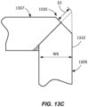
- FIGS. 13A-13C illustrate another transformer core corner 1300 in accordance with the invention.
- Transformer core corner 1300 may be formed using step-lap profile 900 with leg laminations 1305 and yoke laminations 1307, which may be the same as leg laminations 403 and/or 605 and upper yoke laminations 707 and/or lower yoke laminations 806, respectively.
- Each leg lamination 1305 and yoke lamination 1307 may have a second diagonal cut 1330 made prior to transformer core assembly (which may render second cut 1230 unnecessary).
- Second diagonal cut 1330 is made opposite the first diagonal cut, creating an offset V-shape at each longitudinal end of each leg and yoke lamination.
- Second diagonal cut 1330 may be made at an angle A2 (see FIG.
- second diagonal cut 1330 may be made starting at a distance D1 measured along the first diagonal cut from the tip of the longitudinal end of a longest lamination, as shown in FIG. 13C for a longest leg lamination 1305.
- Distance D1 may be about 0.4 x width W6 or less (width W6 may be the same as any one of widths W1-W5).
- Second diagonal cut 1330 may then be made, in some embodiments, at a 45 degree angle with respect to a longitudinal edge 1332.
- Each successively shorter lamination may have second diagonal cut 1330 made at a distance D1 minus the appropriate multiple of the step dimension.
- Each of the four corners of transformer core 102 may be formed identically as transformer core corner 1300 with second diagonal cuts 1330.
- Transformer core corner 1300 advantageously eliminates the 90-degree corner that would otherwise be formed without second diagonal cut 1330, which may further improve magnetic flux performance by improving magnetic flux flow, reducing eddy currents, and/or reducing transformer noise.
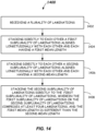
- FIG. 14 illustrates a flowchart of a method 1400 of assembling a transformer core in accordance with one or more embodiments which are not part of the invention.
- Method 500 may include at process block 1402 receiving a plurality of laminations.
- a plurality of laminations may be received that includes leg laminations 403 and/or 605, leg laminations 504, and upper yoke laminations 707 and/or lower yoke laminations 806 in sufficient quantity to construct a transformer core of desired size.
- the longitudinal lengths and transverse widths of each of the leg and yoke laminations may depend on the desired electrical and magnetic properties of the transformer core and the desired step dimensions of the step-lap profile used.
- method 1400 may include stacking directly to each other a first sub-plurality of laminations aligned longitudinally with each other and having a same first mean length.
- method 1400 may include stacking directly to each other a second sub-plurality of laminations aligned longitudinally with each other and having a same second mean length.
- method 1400 may include stacking the second sub-plurality of the laminations directly to the first sub-plurality of the laminations, wherein the first sub-plurality of the laminations or the second sub-plurality of the laminations comprises at least four laminations and the first mean length is different than the second mean length.
- the first sub-plurality of laminations may be laminations 901-5 and the second sub-plurality of laminations may be laminations 901-6, or the first sub-plurality of laminations may be laminations 901-8 and the second sub-plurality of laminations may be laminations 901-9.
- method 1400 may additionally include: stacking directly to each other a third sub-plurality of the laminations aligned longitudinally with each other and each having a third mean length, stacking the third sub-plurality of the laminations directly to the second sub-plurality of the laminations; stacking directly to each other a fourth sub-plurality of the laminations aligned longitudinally with each other and each having a fourth mean length; stacking the fourth sub-plurality of the laminations directly to the third sub-plurality of the laminations; stacking directly to each other a fifth sub-plurality of the laminations aligned longitudinally with each other and each having a fifth mean length; and stacking the fifth sub-plurality of the laminations directly to the fourth sub-plurality of the laminations; wherein the first sub-plurality of the laminations comprises at least four laminations; and (1) the first mean length is longer than the second mean length, the second mean length is longer than the third mean length
- the first, second, third, fourth, and fifth sub-pluralities of laminations may be, respectively, laminations 901-9, 901-8, 901-7, 901-6, and 901-5 (see FIG. 9 ).
- the first, second, third, fourth, and fifth sub-pluralities of laminations may be, respectively, laminations 901-5, 901-6, 901-7, 901-8, and 901-9.
Landscapes
- Engineering & Computer Science (AREA)
- Power Engineering (AREA)
- Manufacturing & Machinery (AREA)
- Manufacturing Cores, Coils, And Magnets (AREA)
- Coils Or Transformers For Communication (AREA)
Claims (11)
- Noyau de transformateur (102), comprenant :
une pluralité de tôles (920, 921, 922, 923, 924) empilées ensemble en une séquence de chevauchement partiel (925) de tôles (920, 921, 922, 923, 924) comprenant :une première sous-pluralité des tôles (920, 921, 922, 923, 924) ayant chacune une première longueur moyenne et alignées longitudinalement et empilées directement les unes sur les autres ; etune deuxième sous-pluralité des tôles (920, 921, 922, 923, 924) ayant chacune une deuxième longueur moyenne et alignées longitudinalement et empilées directement les unes sur les autres, la deuxième sous-pluralité des tôles (920, 921, 922, 923, 924) étant empilée directement sur la première sous-pluralité des tôles (920, 921, 922, 923, 924) ; dans lequel :la première sous-pluralité des tôles (920, 921, 922, 923, 924) ou la deuxième sous-pluralité des tôles (920, 921, 922, 923, 924) comprend au moins quatre tôles (920, 921, 922, 923, 924) ; etla première longueur moyenne est différente de la deuxième longueur moyenne,caractérisé en ce quela séquence de chevauchement partiel (925) comprend au moins 20 tôles (920, 921, 922, 923, 924) qui comprennent au moins quatre tôles identiques alignées longitudinalement et transversalement (901-5) empilées directement les unes sur les autres, chacune ayant une même longueur moyenne minimale de la séquence de chevauchement partiel (925). - Noyau de transformateur selon la revendication 1, dans lequel la première sous-pluralité des tôles (920, 921, 922, 923, 924) comprend au moins quatre tôles (920, 921, 922, 923, 924), et la séquence de chevauchement partiel (925) de tôles (920, 921, 922, 923, 924) comprend en outre :une troisième sous-pluralité des tôles (920, 921, 922, 923, 924) ayant chacune une troisième longueur moyenne et alignées longitudinalement et empilées directement les unes sur les autres, la troisième sous-pluralité des tôles (920, 921, 922, 923, 924) étant empilée directement sur la deuxième sous-pluralité des tôles (920, 921, 922, 923, 924) ;une quatrième sous-pluralité des tôles (920, 921, 922, 923, 924) ayant chacune une quatrième longueur moyenne et alignées longitudinalement et empilées directement les unes sur les autres, la quatrième sous-pluralité des tôles (920, 921, 922, 923, 924) étant empilée directement sur la troisième sous-pluralité des tôles (920, 921, 922, 923, 924) ; etune cinquième sous-pluralité des tôles (920, 921, 922, 923, 924) ayant chacune une cinquième longueur moyenne et alignées longitudinalement et empilées directement les unes sur les autres, la cinquième sous-pluralité des tôles (920, 921, 922, 923, 924) étant empilée directement sur la quatrième sous-pluralité des tôles (920, 921, 922, 923, 924) ; dans lequel :la première longueur moyenne est supérieure à la deuxième longueur moyenne, la deuxième longueur moyenne est supérieure à la troisième longueur moyenne, la troisième longueur moyenne est supérieure à la quatrième longueur moyenne, et la quatrième longueur moyenne est supérieure à la cinquième longueur moyenne ; oula première longueur moyenne est inférieure à la deuxième longueur moyenne, la deuxième longueur moyenne est inférieure à la troisième longueur moyenne, la troisième longueur moyenne est inférieure à la quatrième longueur moyenne, et la quatrième longueur moyenne est inférieure à la cinquième longueur moyenne.
- Noyau de transformateur selon la revendication 2, dans lequel la cinquième sous-pluralité des tôles (920, 921, 922, 923, 924) comprend au moins quatre tôles (920, 921, 922, 923, 924) et/ou dans lequel chaque tôle (920, 921, 922, 923, 924) de la pluralité de tôles (920, 921, 922, 923, 924) a une extrémité longitudinale coupée en diagonale.
- Noyau de transformateur selon la revendication 1, dans lequel la pluralité de tôles (920, 921, 922, 923, 924) comprend une patte verticale du noyau de transformateur (102) et/ou dans lequel chaque tôle (920, 921, 922, 923, 924) de la pluralité de tôles (920, 921, 922, 923, 924) a une extrémité longitudinale en forme de V.
- Noyau de transformateur selon la revendication 1, dans lequel la pluralité de tôles (920, 921, 922, 923, 924) comprend une fourche horizontale du noyau de transformateur (102) et/ou dans lequel chaque tôle (920, 921, 922, 923, 924) de la pluralité de tôles (920, 921, 922, 923, 924) comprend une encoche en forme de V.
- Noyau de transformateur selon la revendication 1, dans lequel chaque tôle (920, 921, 922, 923, 924) de la pluralité de tôles (920, 921, 922, 923, 924) comprend de l'acier électrique et/ou dans lequel la première longueur moyenne est supérieure ou inférieure de 3 mm à 7 mm à la deuxième longueur moyenne et/ou dans lequel chaque tôle (920, 921, 922, 923, 924) de la pluralité de tôles (920, 921, 922, 923, 924) a une même largeur transversale (W1, W2, W2A, W3, W4, W5) et les tôles de la pluralité de tôles (920, 921, 922, 923, 924) sont alignées transversalement.
- Procédé d'assemblage d'un noyau de transformateur (102), comprenant :la réception d'une pluralité de tôles (920, 921, 922, 923, 924) ;l'empilement direct les unes sur les autres d'une première sous-pluralité de tôles (920, 921, 922, 923, 924) alignées longitudinalement les unes avec les autres et ayant chacune une première longueur moyenne ;l'empilement direct les unes sur les autres d'une deuxième sous-pluralité de tôles (920, 921, 922, 923, 924) alignées longitudinalement les unes avec les autres et ayant chacune une deuxième longueur moyenne ; etl'empilement de la deuxième sous-pluralité des tôles (920, 921, 922, 923, 924) directement sur la première sous-pluralité des tôles (920, 921, 922, 923, 924) ; dans lequel :la première sous-pluralité des tôles (920, 921, 922, 923, 924) ou la deuxième sous-pluralité des tôles (920, 921, 922, 923, 924) comprend au moins quatre tôles (920, 921, 922, 923, 924) ; etla première longueur moyenne est différente de la deuxième longueur moyenne,dans lequel la séquence de chevauchement partiel (925) comprend au moins 20 tôles (920, 921, 922, 923, 924) qui comprennent au moins quatre tôles identiques alignés longitudinalement et transversalement (901-5) empilées directement les unes sur les autres, chacune ayant une même longueur moyenne minimale de la séquence de chevauchement partiel (925).
- Procédé selon la revendication 7, dans lequel la première sous-pluralité des tôles (920, 921, 922, 923, 924) comprend au moins quatre tôles (920, 921, 922, 923, 924), le procédé comprenant en outre :l'empilement direct les unes sur les autres d'une troisième sous-pluralité de tôles (920, 921, 922, 923, 924) alignées longitudinalement les unes avec les autres et ayant chacune une troisième longueur moyenne ;l'empilement direct de la troisième sous-pluralité des tôles (920, 921, 922, 923, 924) sur la deuxième sous-pluralité des tôles (920, 921, 922, 923, 924) ;l'empilement direct les unes sur les autres d'une quatrième sous-pluralité de tôles (920, 921, 922, 923, 924) alignées longitudinalement les unes avec les autres et ayant chacune une quatrième longueur moyenne ;l'empilement direct de la quatrième sous-pluralité des tôles (920, 921, 922, 923, 924) sur la troisième sous-pluralité des tôles (920, 921, 922, 923, 924) ;l'empilement direct les unes sur les autres d'une cinquième sous-pluralité de tôles (920, 921, 922, 923, 924) alignées longitudinalement les unes avec les autres et ayant chacune une cinquième longueur moyenne ;l'empilement direct de la cinquième sous-pluralité des tôles (920, 921, 922, 923, 924) sur la quatrième sous-pluralité des tôles (920, 921, 922, 923, 924) ; dans lequel :la première longueur moyenne est supérieure à la deuxième longueur moyenne, la deuxième longueur moyenne est supérieure à la troisième longueur moyenne, la troisième longueur moyenne est supérieure à la quatrième longueur moyenne, et la quatrième longueur moyenne est supérieure à la cinquième longueur moyenne ; oula première longueur moyenne est inférieure à la deuxième longueur moyenne, la deuxième longueur moyenne est inférieure à la troisième longueur moyenne, la troisième longueur moyenne est inférieure à la quatrième longueur moyenne, et la quatrième longueur moyenne est inférieure à la cinquième longueur moyenne.
- Procédé selon la revendication 7, comprenant en outre :la découpe en diagonale d'une extrémité longitudinale de chaque tôle (920, 921, 922, 923, 924) de la pluralité de tôles (920, 921, 922, 923, 924) avant l'empilement ; etla formation d'une patte (103-105) du noyau de transformateur (102) avec des première et deuxième sous-pluralité de tôles (920, 921, 922, 923, 924) empilées.
- Procédé selon la revendication 7, comprenant en outre :la découpe en forme de V à une extrémité longitudinale de chaque tôle (920, 921, 922, 923, 924) de la pluralité de tôles (920, 921, 922, 923, 924) avant l'empilement ; etla formation d'une patte centrale (103-105) du noyau de transformateur (102) avec des première et deuxième sous-pluralité de tôles (920, 921, 922, 923, 924) empilées.
- Procédé selon la revendication 7, comprenant en outre :la découpe d'une encoche en forme de V dans chaque tôle (920, 921, 922, 923, 924) de la pluralité de tôles (920, 921, 922, 923, 924) avant l'empilement ; etla formation d'une fourche (106, 107) du noyau de transformateur (102) avec des première et deuxième sous-pluralité de tôles (920, 921, 922, 923, 924) empilées.
Applications Claiming Priority (1)
| Application Number | Priority Date | Filing Date | Title |
|---|---|---|---|
| PCT/CN2018/084068 WO2019204962A1 (fr) | 2018-04-23 | 2018-04-23 | Noyaux de transformateur et procédés d'assemblage de ceux-ci pour une efficacité élevée et des performances anti-corrosion élevées |
Publications (3)
| Publication Number | Publication Date |
|---|---|
| EP3769324A1 EP3769324A1 (fr) | 2021-01-27 |
| EP3769324A4 EP3769324A4 (fr) | 2022-03-16 |
| EP3769324B1 true EP3769324B1 (fr) | 2023-08-30 |
Family
ID=68293826
Family Applications (1)
| Application Number | Title | Priority Date | Filing Date |
|---|---|---|---|
| EP18916458.5A Active EP3769324B1 (fr) | 2018-04-23 | 2018-04-23 | Noyaux de transformateur et procédés d'assemblage de ceux-ci pour une efficacité élevée et des performances anti-corrosion élevées |
Country Status (6)
| Country | Link |
|---|---|
| US (1) | US11282627B2 (fr) |
| EP (1) | EP3769324B1 (fr) |
| CN (1) | CN112753082B (fr) |
| BR (1) | BR112020021630B8 (fr) |
| CA (1) | CA3097935C (fr) |
| WO (1) | WO2019204962A1 (fr) |
Families Citing this family (6)
| Publication number | Priority date | Publication date | Assignee | Title |
|---|---|---|---|---|
| CN111785501B (zh) * | 2020-05-29 | 2022-05-31 | 天长市烁源磁电有限公司 | 一种磁性铁氧体磁芯制坯用切割装置 |
| CN111508691B (zh) * | 2020-05-29 | 2025-05-16 | 卧龙电气银川变压器有限公司 | 一种变压器铁心 |
| KR20220165900A (ko) * | 2021-06-09 | 2022-12-16 | 주식회사 포스코 | 변압기 철심 및 그 제조방법 |
| CN115656025B (zh) * | 2022-11-22 | 2024-03-12 | 西南交通大学 | 一种海上变压器铁心抗腐蚀能力的评估方法 |
| CN116344170A (zh) * | 2023-03-24 | 2023-06-27 | 无锡巨龙硅钢股份有限公司 | 一种低出角的高阶纵向步进铁芯叠片结构及方法 |
| CN118098773B (zh) * | 2024-03-06 | 2025-02-28 | 浙江南变控股集团有限公司 | 一种变压器铁芯 |
Family Cites Families (29)
| Publication number | Priority date | Publication date | Assignee | Title |
|---|---|---|---|---|
| GB665087A (en) * | 1948-12-17 | 1952-01-16 | British Thomson Houston Co Ltd | Improvements in and relating to laminated magnetic cores, particularly for transformers |
| US2910663A (en) * | 1954-12-29 | 1959-10-27 | Gen Electric | Transformer core clamp connector |
| GB831171A (en) * | 1956-11-29 | 1960-03-23 | Asea Ab | Laminated magnetic core |
| US3129377A (en) * | 1960-11-14 | 1964-04-14 | Westinghouse Electric Corp | Transformer for connecting a threephase system to a two-phase system |
| FR1418765A (fr) * | 1962-11-10 | 1965-11-26 | Procédé pour obtenir une meilleure utilisation des tôles magnétiques à cristaux orientés dans les transformateurs statiques | |
| DE1613654A1 (de) | 1967-03-10 | 1970-05-14 | Funken Josef Dipl Ing | Eisenkern fuer elektrische Induktionsapparate |
| US3411121A (en) * | 1967-06-27 | 1968-11-12 | Gen Electric | Insulated clamping means for laminated magnetic core |
| US3614695A (en) * | 1970-09-24 | 1971-10-19 | Westinghouse Canada Ltd | Inductive apparatus with magnetic locking plates |
| JPS5272420A (en) * | 1975-12-12 | 1977-06-16 | Hitachi Ltd | Inner iron type transformer core |
| US4200854A (en) * | 1979-01-04 | 1980-04-29 | Westinghouse Electric Corp. | Core with step-lap joints |
| US4283842A (en) * | 1979-01-04 | 1981-08-18 | Westinghouse Electric Corp. | Method of making an electrical inductive apparatus |
| US4345232A (en) * | 1979-03-20 | 1982-08-17 | Westinghouse Electric Corp. | Non-metallic core band |
| US4972168A (en) * | 1989-01-03 | 1990-11-20 | Abb Power T & D Company, Inc. | Transformers and cores for transformers |
| US5329270A (en) * | 1992-06-26 | 1994-07-12 | General Electric Company | Transformer core comprising groups of amorphous steel strips wrapped about the core window |
| US5959523A (en) * | 1996-10-15 | 1999-09-28 | Abb Power T&D Company Inc. | Magnetic core structure |
| CN1143329C (zh) | 1997-04-11 | 2004-03-24 | 西门子能量及自动化公司 | 用于变压器等的磁性组件 |
| CN2705865Y (zh) * | 2004-03-18 | 2005-06-22 | 特变电工股份有限公司 | 一种变压器铁心心柱拼接结构 |
| US7256677B2 (en) * | 2005-03-30 | 2007-08-14 | Abb Technology Ag | Transformer having a stacked core with a cruciform leg and a method of making the same |
| US7199696B2 (en) * | 2005-03-30 | 2007-04-03 | Abb Technology Ag | Transformer having a stacked core with a split leg and a method of making the same |
| EP2206126B1 (fr) * | 2007-10-29 | 2012-03-14 | Siemens Transformers Austria GmbH & Co. KG | Noyau de transformateur a blindage a champ de dispersion |
| US8212645B2 (en) | 2008-04-10 | 2012-07-03 | Siemens Aktiengesellschaft | Method for producing a transformer core and a transformer core |
| BRPI0903695A2 (pt) | 2009-05-19 | 2011-02-15 | Siemens Ltda | transformador de distribuição seco submersìvel |
| WO2010148575A1 (fr) * | 2009-06-26 | 2010-12-29 | 特变电工沈阳变压器集团有限公司 | Procédé permettant de réaliser un transformateur de convertisseur pour supprimer un aimant de polarisation en courant continu |
| CN201773673U (zh) * | 2010-03-10 | 2011-03-23 | 天威保变(合肥)变压器有限公司 | 一种简便的步进搭接式铁芯 |
| ES2684578T3 (es) | 2010-04-07 | 2018-10-03 | Abb Schweiz Ag | Transformador tipo seco para exteriores |
| US9576709B2 (en) * | 2010-04-22 | 2017-02-21 | Abb Schweiz Ag | Transformer having a stacked core |
| CN104851566A (zh) * | 2014-02-15 | 2015-08-19 | 无锡巨龙硅钢片有限公司 | 一种用于变压器的混合步进接缝铁芯 |
| US20170040099A1 (en) * | 2014-03-21 | 2017-02-09 | General Electric Company | Electromagnetic apparatus and method for providing the same |
| CN104810140B (zh) * | 2015-05-15 | 2018-03-09 | 东莞市光华实业有限公司 | 可提高组装效率的变压器铁芯 |
-
2018
- 2018-04-23 EP EP18916458.5A patent/EP3769324B1/fr active Active
- 2018-04-23 CN CN201880092716.5A patent/CN112753082B/zh active Active
- 2018-04-23 BR BR112020021630A patent/BR112020021630B8/pt active IP Right Grant
- 2018-04-23 CA CA3097935A patent/CA3097935C/fr active Active
- 2018-04-23 WO PCT/CN2018/084068 patent/WO2019204962A1/fr not_active Ceased
- 2018-04-23 US US17/045,932 patent/US11282627B2/en active Active
Also Published As
| Publication number | Publication date |
|---|---|
| EP3769324A4 (fr) | 2022-03-16 |
| CN112753082A (zh) | 2021-05-04 |
| BR112020021630B1 (pt) | 2022-08-09 |
| CA3097935C (fr) | 2022-08-23 |
| CN112753082B (zh) | 2024-07-19 |
| CA3097935A1 (fr) | 2019-10-31 |
| EP3769324A1 (fr) | 2021-01-27 |
| BR112020021630B8 (pt) | 2023-04-25 |
| US20210057141A1 (en) | 2021-02-25 |
| US11282627B2 (en) | 2022-03-22 |
| BR112020021630A2 (pt) | 2021-01-26 |
| WO2019204962A1 (fr) | 2019-10-31 |
Similar Documents
| Publication | Publication Date | Title |
|---|---|---|
| EP3769324B1 (fr) | Noyaux de transformateur et procédés d'assemblage de ceux-ci pour une efficacité élevée et des performances anti-corrosion élevées | |
| CN110235342B (zh) | 用于电机的定子 | |
| US7582999B2 (en) | Electric machine having a magnetically inducible core | |
| US12142416B2 (en) | Electric motor, motor vehicle, and method for producing a winding for an electric motor | |
| EP2625771B1 (fr) | Bobinage en tôle feuilletée | |
| CN112018921B (zh) | 一种集中式定子及电机 | |
| US10541574B2 (en) | Rotor for electric machine, and manufacturing method of rotor | |
| CN1647347A (zh) | 定子叠片铁芯 | |
| CN203277040U (zh) | 具有层叠型铁芯的配电变压器 | |
| KR960703497A (ko) | 평형구조도체부품으로 제조된 권선이 내장된 다상전기기계(multiphase electric machine with a winding made of flat shaped conductors) | |
| CN102460609A (zh) | 绕组及绕组制造方法 | |
| US12051537B2 (en) | Medium frequency transformer | |
| US20180005756A1 (en) | Plate cut linear motor coil for elevator system | |
| EP0040262A1 (fr) | Bobine de réactance comprenant des enroulements en forme de bandes | |
| EP0941544A1 (fr) | Ameliorations relatives a des bobines | |
| US7064647B2 (en) | Fabricated air core reactor | |
| RU2444076C1 (ru) | Трансформатор | |
| EP4254741A2 (fr) | Réseau de conducteurs pour un enroulement pour une machine électrique | |
| US10916988B1 (en) | Array of conductors for a winding for an electrical machine | |
| Marković | Insulation optimization of power transformer leads | |
| Fogaras et al. | Calculation of electrical field strength around transformer winding corners | |
| Shuman et al. | A large bore pulsed quadrupole magnet for transport of high current beams at low energies | |
| RU2647876C1 (ru) | Сварочный трансформатор | |
| CN121569355A (zh) | 用于拆卸/运输变压器的铁芯 | |
| JPS61273165A (ja) | 溶湯搬送用誘導子 |
Legal Events
| Date | Code | Title | Description |
|---|---|---|---|
| STAA | Information on the status of an ep patent application or granted ep patent |
Free format text: STATUS: THE INTERNATIONAL PUBLICATION HAS BEEN MADE |
|
| PUAI | Public reference made under article 153(3) epc to a published international application that has entered the european phase |
Free format text: ORIGINAL CODE: 0009012 |
|
| STAA | Information on the status of an ep patent application or granted ep patent |
Free format text: STATUS: REQUEST FOR EXAMINATION WAS MADE |
|
| 17P | Request for examination filed |
Effective date: 20201020 |
|
| AK | Designated contracting states |
Kind code of ref document: A1 Designated state(s): AL AT BE BG CH CY CZ DE DK EE ES FI FR GB GR HR HU IE IS IT LI LT LU LV MC MK MT NL NO PL PT RO RS SE SI SK SM TR |
|
| AX | Request for extension of the european patent |
Extension state: BA ME |
|
| DAV | Request for validation of the european patent (deleted) | ||
| DAX | Request for extension of the european patent (deleted) | ||
| A4 | Supplementary search report drawn up and despatched |
Effective date: 20220210 |
|
| RIC1 | Information provided on ipc code assigned before grant |
Ipc: H01F 27/245 20060101AFI20220204BHEP |
|
| STAA | Information on the status of an ep patent application or granted ep patent |
Free format text: STATUS: EXAMINATION IS IN PROGRESS |
|
| 17Q | First examination report despatched |
Effective date: 20221125 |
|
| GRAP | Despatch of communication of intention to grant a patent |
Free format text: ORIGINAL CODE: EPIDOSNIGR1 |
|
| STAA | Information on the status of an ep patent application or granted ep patent |
Free format text: STATUS: GRANT OF PATENT IS INTENDED |
|
| RAP1 | Party data changed (applicant data changed or rights of an application transferred) |
Owner name: LI, HUI Owner name: CHEN, WEI Owner name: MORENO, ANDRE LUIZ Owner name: NAVARRO, MARTIN ALSINA Owner name: WANG, ZHONGBO Owner name: HAINAN JINPAN SMART TECHNOLOGY CO., LTD. Owner name: SIEMENS ENERGY GLOBAL GMBH & CO. KG |
|
| INTG | Intention to grant announced |
Effective date: 20230328 |
|
| RIN1 | Information on inventor provided before grant (corrected) |
Inventor name: LI, HUI Inventor name: CHEN, WEI Inventor name: MORENO, ANDRE LUIZ Inventor name: NAVARRO, MARTIN ALSINA Inventor name: WANG, ZHONGBO |
|
| GRAS | Grant fee paid |
Free format text: ORIGINAL CODE: EPIDOSNIGR3 |
|
| GRAA | (expected) grant |
Free format text: ORIGINAL CODE: 0009210 |
|
| STAA | Information on the status of an ep patent application or granted ep patent |
Free format text: STATUS: THE PATENT HAS BEEN GRANTED |
|
| AK | Designated contracting states |
Kind code of ref document: B1 Designated state(s): AL AT BE BG CH CY CZ DE DK EE ES FI FR GB GR HR HU IE IS IT LI LT LU LV MC MK MT NL NO PL PT RO RS SE SI SK SM TR |
|
| REG | Reference to a national code |
Ref country code: GB Ref legal event code: FG4D |
|
| REG | Reference to a national code |
Ref country code: CH Ref legal event code: EP |
|
| REG | Reference to a national code |
Ref country code: DE Ref legal event code: R096 Ref document number: 602018056766 Country of ref document: DE |
|
| REG | Reference to a national code |
Ref country code: IE Ref legal event code: FG4D |
|
| REG | Reference to a national code |
Ref country code: LT Ref legal event code: MG9D |
|
| REG | Reference to a national code |
Ref country code: NL Ref legal event code: MP Effective date: 20230830 |
|
| REG | Reference to a national code |
Ref country code: AT Ref legal event code: MK05 Ref document number: 1606513 Country of ref document: AT Kind code of ref document: T Effective date: 20230830 |
|
| PG25 | Lapsed in a contracting state [announced via postgrant information from national office to epo] |
Ref country code: GR Free format text: LAPSE BECAUSE OF FAILURE TO SUBMIT A TRANSLATION OF THE DESCRIPTION OR TO PAY THE FEE WITHIN THE PRESCRIBED TIME-LIMIT Effective date: 20231201 |
|
| PG25 | Lapsed in a contracting state [announced via postgrant information from national office to epo] |
Ref country code: IS Free format text: LAPSE BECAUSE OF FAILURE TO SUBMIT A TRANSLATION OF THE DESCRIPTION OR TO PAY THE FEE WITHIN THE PRESCRIBED TIME-LIMIT Effective date: 20231230 |
|
| PG25 | Lapsed in a contracting state [announced via postgrant information from national office to epo] |
Ref country code: SE Free format text: LAPSE BECAUSE OF FAILURE TO SUBMIT A TRANSLATION OF THE DESCRIPTION OR TO PAY THE FEE WITHIN THE PRESCRIBED TIME-LIMIT Effective date: 20230830 Ref country code: RS Free format text: LAPSE BECAUSE OF FAILURE TO SUBMIT A TRANSLATION OF THE DESCRIPTION OR TO PAY THE FEE WITHIN THE PRESCRIBED TIME-LIMIT Effective date: 20230830 Ref country code: NO Free format text: LAPSE BECAUSE OF FAILURE TO SUBMIT A TRANSLATION OF THE DESCRIPTION OR TO PAY THE FEE WITHIN THE PRESCRIBED TIME-LIMIT Effective date: 20231130 Ref country code: LV Free format text: LAPSE BECAUSE OF FAILURE TO SUBMIT A TRANSLATION OF THE DESCRIPTION OR TO PAY THE FEE WITHIN THE PRESCRIBED TIME-LIMIT Effective date: 20230830 Ref country code: LT Free format text: LAPSE BECAUSE OF FAILURE TO SUBMIT A TRANSLATION OF THE DESCRIPTION OR TO PAY THE FEE WITHIN THE PRESCRIBED TIME-LIMIT Effective date: 20230830 Ref country code: IS Free format text: LAPSE BECAUSE OF FAILURE TO SUBMIT A TRANSLATION OF THE DESCRIPTION OR TO PAY THE FEE WITHIN THE PRESCRIBED TIME-LIMIT Effective date: 20231230 Ref country code: HR Free format text: LAPSE BECAUSE OF FAILURE TO SUBMIT A TRANSLATION OF THE DESCRIPTION OR TO PAY THE FEE WITHIN THE PRESCRIBED TIME-LIMIT Effective date: 20230830 Ref country code: GR Free format text: LAPSE BECAUSE OF FAILURE TO SUBMIT A TRANSLATION OF THE DESCRIPTION OR TO PAY THE FEE WITHIN THE PRESCRIBED TIME-LIMIT Effective date: 20231201 Ref country code: FI Free format text: LAPSE BECAUSE OF FAILURE TO SUBMIT A TRANSLATION OF THE DESCRIPTION OR TO PAY THE FEE WITHIN THE PRESCRIBED TIME-LIMIT Effective date: 20230830 Ref country code: AT Free format text: LAPSE BECAUSE OF FAILURE TO SUBMIT A TRANSLATION OF THE DESCRIPTION OR TO PAY THE FEE WITHIN THE PRESCRIBED TIME-LIMIT Effective date: 20230830 |
|
| PG25 | Lapsed in a contracting state [announced via postgrant information from national office to epo] |
Ref country code: PL Free format text: LAPSE BECAUSE OF FAILURE TO SUBMIT A TRANSLATION OF THE DESCRIPTION OR TO PAY THE FEE WITHIN THE PRESCRIBED TIME-LIMIT Effective date: 20230830 Ref country code: NL Free format text: LAPSE BECAUSE OF FAILURE TO SUBMIT A TRANSLATION OF THE DESCRIPTION OR TO PAY THE FEE WITHIN THE PRESCRIBED TIME-LIMIT Effective date: 20230830 |
|
| PG25 | Lapsed in a contracting state [announced via postgrant information from national office to epo] |
Ref country code: ES Free format text: LAPSE BECAUSE OF FAILURE TO SUBMIT A TRANSLATION OF THE DESCRIPTION OR TO PAY THE FEE WITHIN THE PRESCRIBED TIME-LIMIT Effective date: 20230830 |
|
| PG25 | Lapsed in a contracting state [announced via postgrant information from national office to epo] |
Ref country code: SM Free format text: LAPSE BECAUSE OF FAILURE TO SUBMIT A TRANSLATION OF THE DESCRIPTION OR TO PAY THE FEE WITHIN THE PRESCRIBED TIME-LIMIT Effective date: 20230830 Ref country code: RO Free format text: LAPSE BECAUSE OF FAILURE TO SUBMIT A TRANSLATION OF THE DESCRIPTION OR TO PAY THE FEE WITHIN THE PRESCRIBED TIME-LIMIT Effective date: 20230830 Ref country code: ES Free format text: LAPSE BECAUSE OF FAILURE TO SUBMIT A TRANSLATION OF THE DESCRIPTION OR TO PAY THE FEE WITHIN THE PRESCRIBED TIME-LIMIT Effective date: 20230830 Ref country code: EE Free format text: LAPSE BECAUSE OF FAILURE TO SUBMIT A TRANSLATION OF THE DESCRIPTION OR TO PAY THE FEE WITHIN THE PRESCRIBED TIME-LIMIT Effective date: 20230830 Ref country code: DK Free format text: LAPSE BECAUSE OF FAILURE TO SUBMIT A TRANSLATION OF THE DESCRIPTION OR TO PAY THE FEE WITHIN THE PRESCRIBED TIME-LIMIT Effective date: 20230830 Ref country code: CZ Free format text: LAPSE BECAUSE OF FAILURE TO SUBMIT A TRANSLATION OF THE DESCRIPTION OR TO PAY THE FEE WITHIN THE PRESCRIBED TIME-LIMIT Effective date: 20230830 Ref country code: SK Free format text: LAPSE BECAUSE OF FAILURE TO SUBMIT A TRANSLATION OF THE DESCRIPTION OR TO PAY THE FEE WITHIN THE PRESCRIBED TIME-LIMIT Effective date: 20230830 Ref country code: PT Free format text: LAPSE BECAUSE OF FAILURE TO SUBMIT A TRANSLATION OF THE DESCRIPTION OR TO PAY THE FEE WITHIN THE PRESCRIBED TIME-LIMIT Effective date: 20240102 |
|
| PG25 | Lapsed in a contracting state [announced via postgrant information from national office to epo] |
Ref country code: IT Free format text: LAPSE BECAUSE OF FAILURE TO SUBMIT A TRANSLATION OF THE DESCRIPTION OR TO PAY THE FEE WITHIN THE PRESCRIBED TIME-LIMIT Effective date: 20230830 |
|
| REG | Reference to a national code |
Ref country code: DE Ref legal event code: R097 Ref document number: 602018056766 Country of ref document: DE |
|
| PLBE | No opposition filed within time limit |
Free format text: ORIGINAL CODE: 0009261 |
|
| STAA | Information on the status of an ep patent application or granted ep patent |
Free format text: STATUS: NO OPPOSITION FILED WITHIN TIME LIMIT |
|
| PG25 | Lapsed in a contracting state [announced via postgrant information from national office to epo] |
Ref country code: SI Free format text: LAPSE BECAUSE OF FAILURE TO SUBMIT A TRANSLATION OF THE DESCRIPTION OR TO PAY THE FEE WITHIN THE PRESCRIBED TIME-LIMIT Effective date: 20230830 |
|
| 26N | No opposition filed |
Effective date: 20240603 |
|
| REG | Reference to a national code |
Ref country code: DE Ref legal event code: R119 Ref document number: 602018056766 Country of ref document: DE |
|
| PG25 | Lapsed in a contracting state [announced via postgrant information from national office to epo] |
Ref country code: BG Free format text: LAPSE BECAUSE OF FAILURE TO SUBMIT A TRANSLATION OF THE DESCRIPTION OR TO PAY THE FEE WITHIN THE PRESCRIBED TIME-LIMIT Effective date: 20230830 |
|
| PG25 | Lapsed in a contracting state [announced via postgrant information from national office to epo] |
Ref country code: MC Free format text: LAPSE BECAUSE OF FAILURE TO SUBMIT A TRANSLATION OF THE DESCRIPTION OR TO PAY THE FEE WITHIN THE PRESCRIBED TIME-LIMIT Effective date: 20230830 |
|
| PG25 | Lapsed in a contracting state [announced via postgrant information from national office to epo] |
Ref country code: MC Free format text: LAPSE BECAUSE OF FAILURE TO SUBMIT A TRANSLATION OF THE DESCRIPTION OR TO PAY THE FEE WITHIN THE PRESCRIBED TIME-LIMIT Effective date: 20230830 Ref country code: BG Free format text: LAPSE BECAUSE OF FAILURE TO SUBMIT A TRANSLATION OF THE DESCRIPTION OR TO PAY THE FEE WITHIN THE PRESCRIBED TIME-LIMIT Effective date: 20230830 |
|
| REG | Reference to a national code |
Ref country code: CH Ref legal event code: PL |
|
| PG25 | Lapsed in a contracting state [announced via postgrant information from national office to epo] |
Ref country code: LU Free format text: LAPSE BECAUSE OF NON-PAYMENT OF DUE FEES Effective date: 20240423 |
|
| GBPC | Gb: european patent ceased through non-payment of renewal fee |
Effective date: 20240423 |
|
| REG | Reference to a national code |
Ref country code: BE Ref legal event code: MM Effective date: 20240430 |
|
| PG25 | Lapsed in a contracting state [announced via postgrant information from national office to epo] |
Ref country code: LU Free format text: LAPSE BECAUSE OF NON-PAYMENT OF DUE FEES Effective date: 20240423 |
|
| PG25 | Lapsed in a contracting state [announced via postgrant information from national office to epo] |
Ref country code: DE Free format text: LAPSE BECAUSE OF NON-PAYMENT OF DUE FEES Effective date: 20241105 |
|
| PG25 | Lapsed in a contracting state [announced via postgrant information from national office to epo] |
Ref country code: BE Free format text: LAPSE BECAUSE OF NON-PAYMENT OF DUE FEES Effective date: 20240430 |
|
| PG25 | Lapsed in a contracting state [announced via postgrant information from national office to epo] |
Ref country code: GB Free format text: LAPSE BECAUSE OF NON-PAYMENT OF DUE FEES Effective date: 20240423 |
|
| PG25 | Lapsed in a contracting state [announced via postgrant information from national office to epo] |
Ref country code: FR Free format text: LAPSE BECAUSE OF NON-PAYMENT OF DUE FEES Effective date: 20240430 |
|
| PG25 | Lapsed in a contracting state [announced via postgrant information from national office to epo] |
Ref country code: GB Free format text: LAPSE BECAUSE OF NON-PAYMENT OF DUE FEES Effective date: 20240423 Ref country code: FR Free format text: LAPSE BECAUSE OF NON-PAYMENT OF DUE FEES Effective date: 20240430 Ref country code: DE Free format text: LAPSE BECAUSE OF NON-PAYMENT OF DUE FEES Effective date: 20241105 Ref country code: BE Free format text: LAPSE BECAUSE OF NON-PAYMENT OF DUE FEES Effective date: 20240430 Ref country code: CH Free format text: LAPSE BECAUSE OF NON-PAYMENT OF DUE FEES Effective date: 20240430 |
|
| PG25 | Lapsed in a contracting state [announced via postgrant information from national office to epo] |
Ref country code: IE Free format text: LAPSE BECAUSE OF NON-PAYMENT OF DUE FEES Effective date: 20240423 |
|
| PG25 | Lapsed in a contracting state [announced via postgrant information from national office to epo] |
Ref country code: CY Free format text: LAPSE BECAUSE OF FAILURE TO SUBMIT A TRANSLATION OF THE DESCRIPTION OR TO PAY THE FEE WITHIN THE PRESCRIBED TIME-LIMIT; INVALID AB INITIO Effective date: 20180423 |
|
| PG25 | Lapsed in a contracting state [announced via postgrant information from national office to epo] |
Ref country code: HU Free format text: LAPSE BECAUSE OF FAILURE TO SUBMIT A TRANSLATION OF THE DESCRIPTION OR TO PAY THE FEE WITHIN THE PRESCRIBED TIME-LIMIT; INVALID AB INITIO Effective date: 20180423 |