EP3769580B1 - Verfahren und system zur anzeige einer änderung bei der dualen konnektivitätskapazität einer mehrfunkzugangstechnologie - Google Patents
Verfahren und system zur anzeige einer änderung bei der dualen konnektivitätskapazität einer mehrfunkzugangstechnologie Download PDFInfo
- Publication number
- EP3769580B1 EP3769580B1 EP19843289.0A EP19843289A EP3769580B1 EP 3769580 B1 EP3769580 B1 EP 3769580B1 EP 19843289 A EP19843289 A EP 19843289A EP 3769580 B1 EP3769580 B1 EP 3769580B1
- Authority
- EP
- European Patent Office
- Prior art keywords
- capability
- network node
- change
- response
- message
- Prior art date
- Legal status (The legal status is an assumption and is not a legal conclusion. Google has not performed a legal analysis and makes no representation as to the accuracy of the status listed.)
- Active
Links
Images





Classifications
-
- H—ELECTRICITY
- H04—ELECTRIC COMMUNICATION TECHNIQUE
- H04W—WIRELESS COMMUNICATION NETWORKS
- H04W8/00—Network data management
- H04W8/22—Processing or transfer of terminal data, e.g. status or physical capabilities
-
- H—ELECTRICITY
- H04—ELECTRIC COMMUNICATION TECHNIQUE
- H04W—WIRELESS COMMUNICATION NETWORKS
- H04W4/00—Services specially adapted for wireless communication networks; Facilities therefor
- H04W4/12—Messaging; Mailboxes; Announcements
- H04W4/14—Short messaging services, e.g. short message services [SMS] or unstructured supplementary service data [USSD]
-
- H—ELECTRICITY
- H04—ELECTRIC COMMUNICATION TECHNIQUE
- H04W—WIRELESS COMMUNICATION NETWORKS
- H04W60/00—Affiliation to network, e.g. registration; Terminating affiliation with the network, e.g. de-registration
- H04W60/04—Affiliation to network, e.g. registration; Terminating affiliation with the network, e.g. de-registration using triggered events
-
- H—ELECTRICITY
- H04—ELECTRIC COMMUNICATION TECHNIQUE
- H04W—WIRELESS COMMUNICATION NETWORKS
- H04W76/00—Connection management
- H04W76/10—Connection setup
- H04W76/15—Setup of multiple wireless link connections
- H04W76/16—Involving different core network technologies, e.g. a packet-switched [PS] bearer in combination with a circuit-switched [CS] bearer
-
- H—ELECTRICITY
- H04—ELECTRIC COMMUNICATION TECHNIQUE
- H04W—WIRELESS COMMUNICATION NETWORKS
- H04W76/00—Connection management
- H04W76/30—Connection release
-
- H—ELECTRICITY
- H04—ELECTRIC COMMUNICATION TECHNIQUE
- H04W—WIRELESS COMMUNICATION NETWORKS
- H04W8/00—Network data management
- H04W8/22—Processing or transfer of terminal data, e.g. status or physical capabilities
- H04W8/24—Transfer of terminal data
-
- H—ELECTRICITY
- H04—ELECTRIC COMMUNICATION TECHNIQUE
- H04W—WIRELESS COMMUNICATION NETWORKS
- H04W76/00—Connection management
- H04W76/20—Manipulation of established connections
- H04W76/27—Transitions between radio resource control [RRC] states
-
- H—ELECTRICITY
- H04—ELECTRIC COMMUNICATION TECHNIQUE
- H04W—WIRELESS COMMUNICATION NETWORKS
- H04W88/00—Devices specially adapted for wireless communication networks, e.g. terminals, base stations or access point devices
- H04W88/02—Terminal devices
- H04W88/06—Terminal devices adapted for operation in multiple networks or having at least two operational modes, e.g. multi-mode terminals
Definitions
- the present disclosure relates to an indication of a change in a dual connectivity capability of a User Equipment (UE) and more specifically to a method for indicating the change in a Multi-Radio Access Technology (RAT) dual connectivity (MR-DC) capability of the UE.
- UE User Equipment
- RAT Multi-Radio Access Technology
- MR-DC Multi-Radio Access Technology
- MR-DC Multi-RAT Dual Connectivity
- UE User Equipment
- 5G 5 th Generation
- a Master RAN Node MN
- SN Secondary RAN Node
- Examples of MR-DC configurations for the UE include EN-DC (E-UTRA - NR Dual Connectivity) configuration, NR-NR-DC (New Radio-New Radio Dual Connectivity) configuration, NGEN-DC (NG-RAN - E-UTRA Dual Connectivity) configuration, NE-DC (NR - E-UTRA Dual Connectivity) configuration and the like.
- EN-DC E-UTRA - NR Dual Connectivity
- NR-NR-DC New Radio-New Radio Dual Connectivity
- NGEN-DC NG-RAN - E-UTRA Dual Connectivity
- NE-DC NR - E-UTRA Dual Connectivity
- MR-DC is described as in REL-15 3GPP standards (TS 37.340), where multiple transmitters and receivers (Tx/Rx) at the UE may be configured to utilize radio resources of both NR (New Radio) and EUTRA (Evolved-Universal Terrestrial Radio Access-New Radio) in an ENDC configuration.
- the UE is connected to eNB (evolved node B) that acts as MN and one gNB (5 th Generation node B) that acts as SN.
- eNB evolved node B
- gNB 5 th Generation node B
- the UE indicates this capability to operate on the MR-DC using UE capability information message to a network node.
- the UE has to indicate the networks of its MR-DC capability.
- APPLE INC "UE overheating for EN-DC", 3GPP DRAFT; R2-1802414 UE OVERHEATING FOR EN-DC V2, 3RD GENERATION PARTNERSHIP PROJECT (3GPP), MOBILE COMPETENCE CENTRE ; 650, ROUTE DES LUCIOLES ; F-06921 SOPHIA-ANTIPOLIS CEDEX ; FRANCE, vol. RAN WG2, no.
- WO 2013/091665 A1 relates to user equipment (UE) radio capability handling in LTE (long term evolution).
- CATT "UE capability temporary restrictions", 3GPP DRAFT; R2-1707891, 3RD GENERATION PARTNERSHIP PROJECT (3GPP), MOBILE COMPETENCE CENTRE ; 650, ROUTE DES LUCIOLES ; F-06921 SOPHIA-ANTIPOLIS CEDEX ; FRANCE, vol. RAN WG2, no.
- HUAWEI "Report of email discussion [97#59][LTE/TEI14] UE requested configuration changes", 3GPP DRAFT; R2-1703475, 3RD GENERATION PARTNERSHIP PROJECT (3GPP), MOBILE COMPETENCE CENTRE ; 650, ROUTE DES LUCIOLES ; F-06921 SOPHIA-ANTIPOLIS CEDEX ; FRANCE, vol. RAN WG2, no. Spokane, US; 20170403 - 20170407 3 April 2017 (2017-04-03 ), discusses use cases for UE requested configuration change.
- UE overheating for EN-DC discloses providing power preference indications from a UE to the network and the network acts based on the indications.
- the existing system has limitations in realizing signaling overhead to disable/enable the MR-DC capability. Further, the system does not allow the UE capability change in EMM (EPS Mobility Management)-connected state.
- EMM EPS Mobility Management
- the MR-DC capable UE encounters local trigger to deactivate NR modem to disable the MR-DC capability.
- the UE needs to initiate TAU (Tracking Area Update) procedure and send signaling messages to the RAN for updating the RANs about the deactivation of the NR Modem at the UE.
- the signaling messages includes RACH (Random access channel)procedures with EUTRAN (Evolved Universal Terrestrial Radio Access Network), security procedure between UE and EUTRAN, radio capability request procedures between MME (Mobile Management Entity) and EUTRAN, the UE capability update between UE and EUTRAN, the UE capability indication between EUTRAN and MME and TAU procedures among the UE, EUTRAN and MME.
- the principal object of the embodiments herein is to provide a method and system for indication of a change in an MR-DC capability of the UE to the RANs and core network.
- Another object of the embodiment herein is to hold a Tracking Area Update (TAU) message at the UE while updating the change in the MR-DC capability of the UE to the RANs and core network.
- TAU Tracking Area Update
- Another object of the embodiment herein is to identify detection of a particular event when the UE is in connected mode.
- Another object of the embodiment herein is to identify configuration of UE-assistance information when the UE is in connected mode.
- Another object of the embodiment herein is to regulate the indication of a change in the MR-DC capability of the UE to the network node.
- circuits may, for example, be embodied in one or more semiconductor chips, or on substrate supports such as printed circuit boards and the like.
- circuits constituting a block may be implemented by dedicated hardware, or by a processor (e.g., one or more programmed microprocessors and associated circuitry), or by a combination of dedicated hardware to perform some functions of the block and a processor to perform other functions of the block.
- a processor e.g., one or more programmed microprocessors and associated circuitry
- Each block of the embodiments may be physically separated into two or more interacting and discrete blocks without departing from the scope of the disclosure.
- the blocks of the embodiments may be physically combined into more complex blocks without departing from the scope of the disclosure.
- the embodiments herein disclose a method for indicating the change in the MR-DC capability of the UE to the network node.
- the method comprises detecting a change in the MR-DC capability of the UE and determining, whether the UE is in one of an idle mode and a connected mode.
- the method further comprises holding a tracking area update (TAU) message at the UE, if the UE is in the idle mode, and determining whether a particular event is detected, and regulating an indication of the change in the MR-DC capability of the UE to the network node based on the detection of the particular event.
- TAU tracking area update
- the particular event comprises at least one of an MO/MT request, a data request, a signalling request, and a SMS request, and wherein the particular event configures the UE into the connected mode.
- the method further comprises determining whether UE-assistance information is configured by the network node, when the UE is in connected mode and regulating an indication of the change in the MR-DC capability of the UE to the network node based on the configuration of the UE-assistance information with the network node.
- the proposed method reduces signaling overhead and ensures successful indication of the change in MR-DC capability of the UE to the network node.
- the proposed method also ensures indication of the change in MR-DC capability of the UE to the network node while in a connected mode.
- the UE is first changes to idle mode and then the indication is sent to the network node.
- FIGS. 3 through 22 where similar reference characters denote corresponding features consistently throughout the figures, there are shown preferred embodiments.
- FIG. 1 represents a system diagram of a UE 100 with an MR-DC capability.
- the UE 100 is in connection with both an LTE (Long Term Evolution) eNB 106 and an NR (New Radio) gNB 108.
- the eNB 106 is a master node (MN) and the gNB 108 is a secondary node (SN).
- the eNB 106 and the gNB 108 are connected to an S-GW 104 (Serving Gateway) which acts as a core network.
- the eNB 106 is also connected to an MME 102 (Mobile Management Entity) which is also a part of the core network.
- MN Master node
- SN secondary node
- S-GW 104 Serving Gateway
- MME 102 Mobile Management Entity
- the MR-DC capability of the UE 100 needs to be changed dynamically that is the dual capability of the UE 100 may be enabled or disabled based on an occurrence of a local trigger event from the UE 100.
- the local trigger event may be at least one of a low battery trigger, a high temperature trigger and the like.
- the secondary RAT (secondary modem) (SN) 108 is necessary to deactivate the secondary RAT (secondary modem) (SN) 108 from the dual connectivity of the UE 100.
- SN secondary modem
- This change in the MR-DC capability of the UE 100 has to be indicated to the core network MME 102 and S-GW 104.
- a TAU procedure is initiated by the UE 100.
- Signaling messages get exchanged between the UE 100, eNB 106, gNB 108 and the core network MME 102 and S-GW 104, when the TAU procedure is initiated.
- the signaling messages includes RACH procedures between the UE 100, the eNB 106 and the gNB 108, security procedure between UE 100, eNB 106, and gNB 108 and radio capability request procedures between S-GW 104, MME 102, eNB 106 and the gNB 104, the UE capability update between the UE 100, the eNB 106, and the gNB 108, the UE capability indication between the enb 106, the gnb 108, the S-GW 104 and the MME 102 and TAU procedures between the UE 100, the eNB 106, the gNB 108, the S-GW 104 and the MME 102.
- FIG. 2 depicts a sequence diagram illustrating the signaling procedure of updating the eNB 106 and the MME 102 of the change in the MR-DC capability of the UE 100 for the conventional method.
- the TAU procedure relates to a series of procedures performed by the UE 100 for updating the Tracking Area (TA).
- the TAU procedure (202) is initiated between the UE 100 and the MME 102.
- an RACH procedure (204) between the UE 100 and eNB 106 has to be exchanged.
- the signaling further includes exchanging a security procedure (206) between the UE 100 and eNB 106.
- a radio capability request procedures (208) between the MME 102 and the eNB 106 is also exchanged.
- the UE capability update between the UE 100 and the eNB 106 and the UE capability indication between the eNB 106 and the MME 102 is also exchanged.
- the TAU procedures between the UE 100, the eNB 106 and the MME 102 are also initiated.
- a lot of signaling message exchanges need to happen just to update the UE capability between the UE 100, the MME 102 and the eNB 106.
- There arises a problem of signaling overhead whenever the UE 100 has to change the mode.
- the MR-DC capability of the UE 100 needs to be changes and thus for every change in the MR-DC capability, the TAU procedures, the security procedure and the other signaling has to be done. This results in ping pong effect.
- the prior arts/conventional system and method discloses changing the UE 100 to idle mode first and then updating the network about the changed MR-DC capability of the UE 100.
- conventional systems and method does not state anything about updating the MR-DC capability while the UE 100 is in the connected mode.
- the proposed system and method provides a solution to the above said problems.
- the proposed system and method also provide the feature of updating the MR-DC capability while the UE 100 is in the connected mode.
- FIG. 3 discloses a UE 100 for the proposed method for indicating the change in the MR-DC capability of the UE 100 to the MME 102 and the eNB 106.
- the examples for the UE 100 are, but not limited to a smart phone, a tablet computer, a personal computer, a desktop computer, a mobile device, a personal digital assistance (PDA), a multimedia device, an Internet of Things (IoT) and the like.
- the UE 100 is an MR-DC capable UE.
- the UE 100 may comprise multiple transceivers Tx/Rx and is configured to utilize radio resources of both NR (New Radio) and EUTRA (Evolved-Universal Terrestrial Radio Access-New Radio).
- the UE 100 may be connected to one eNB that acts as an MN 106 (Master Node) and one gNB that acts as SN (secondary node) 108.
- the MR-DC capability of the MR-DC capable UE 100 has to be enabled/disabled dynamically based on the occurrence of the local trigger.
- the change in the MR-DC capability of the UE 100 has to be indicated to the EUTRA 106 and the MME 102.
- the UE 100 is in a connected mode or an idle mode with respect to the network. In the idle mode, the UE 100 has no signaling or data bearers associated with it. In other words, no network/radio resources are allocated to the UE 100. In the connected mode, the UE is associated with the network/radio resources.
- the UE 100 comprises a memory 310, a processor 320, and an MR-DC connectivity regulator 330.
- the MR-DC connectivity regulator 330 comprises a TAU trigger 332, an event detector 334 and a timer 336.
- the MR-DC connectivity regulator 330 is configured to indicate the change in the MR-DC capability of the UE 100 to the MME 102 and the eNB 106.
- the MR-DC connectivity regulator 330 detects the change in the MR-DC capability of the UE 100.
- the MR-DC connectivity regulator 330 is configured to determine whether the UE 100 is in one of the idle mode and the connected mode. If the UE 100 is in the idle mode then the TAU trigger 332 holds the TAU message at the UE 100.
- the event detector 334 determines whether an event is detected, and the MR-DC connectivity regulator 330 regulates an indication of the change in the MR-DC capability of the UE 100 to the MME 102 and the eNB 106 upon detection of the event.
- the event comprises at least one of a Mobile terminated/Mobile originated (MO/MT) request, a data request, a signaling request, and an SMS request, which configures the UE 100 into the connected mode.
- MO/MT Mobile terminated/Mobile originated
- the MO/MT trigger is a trigger by the UE 100 establishing the connection with the network either for mobile originated or mobile terminated cases.
- the MR-DC connectivity regulator 330 determines whether UE-assistance information is configured by the network node.
- the TAU trigger 332 triggers the message indicating the change in the MR-DC capability of the UE 100 to the MME 102 and the EUTRA based on the configuration of the UE-assistance information with the network node.
- a secondary cell group (SCG) failure indication message is triggered by the MR-DC connectivity regulator 330.
- the timer 336 is initiated to receive an acknowledgement of the SCG failure indication message.
- the MR-DC connectivity regulator 330 determines that the timer 336 is expired and the acknowledgement of the SCG failure indication message is not received or the acknowledgement of the SCG failure indication message is received before expiry of the timer 336.
- the TAU trigger 332 triggers the message indicating the change in the MR-DC capability of the UE 100 to the EUTRA and the MME, in response to determining that the DC for the SN is configured.
- FIG. 4 shows a flow diagram 400 for sending TAU messages to the EUTRA 106 and the MME 102 when the UE 100 is in an idle mode.
- the local trigger is received.
- the MR-DC capability of the UE 100 is enabled/disabled based on the local trigger.
- the MR-DC connectivity regulator 330 determines whether the UE is in the idle mode or connected mode. The method proceeds to step 406 if the UE 100 is in the idle mode and to 2 if the UE 100 is in the connected mode.
- the TAU trigger 332 keeps the TAU message pending at the UE 100.
- the MO/MT (mobile originated/mobile terminated) trigger is received.
- the TAU trigger 332 sends the TAU messages to the network indicating the change in the MR-DC capability of the UE 100.
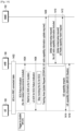
- FIGS. 5a and 5b disclose a sequence diagram of the flow 400 explaining the updating of the EUTRAN and the MME 102 of the change in the MR-DC capability of the UE 100 when the UE 100 is in the idle mode.
- the sequence diagram shows the UE 100, the EUTRA 106 and the MME 102.
- the sequence diagram explains the process of indicating the MR-DC capability of the UE 100 to the network when the UE 100 is in the idle mode.
- the trigger to disable the MR-DC is received, while the UE 100 is in the idle mode.
- the TAU messages are kept pending at the UE 100 by the TAU trigger 322 until the MO/MT trigger is received.
- the MO/MT trigger is received and the UE 100 checks if the trigger to disable the MR-DC capability of the UE still exists. If the trigger to disable the MR-DC capability of the UE 100 is valid then the UE 100 requests an RRC (Radio Resource Control) to send the TAU messages with radio capability update to the network.
- the RRC connection has to be established with the EUTRA 106 to send the MR-DC capability update of the UE 100 to the network.
- an RACH procedure is followed.
- the RACH procedure refer to the first message from the UE 100 to the eNB 106, when the UE 100 is powered and is used for uplink synchronization between the UE 100 and the eNB 106.
- a Random Access Preamble (MSG1) is sent to the EUTRA 106.
- a Random Access Response (MSG2) is received by the UE from the EUTRA 106.
- An RRC Connection Request (MSG3) is sent to the EUTRA 106.
- an RRC Connection Setup (MSG4) is received by the UE 100.
- the RRC connection is completed and the TAU message is encapsulated and the uplink information transfer is done as the message is sent to the EUTRA 106.
- the EUTRA 106 sends the TAU messages to the MME 102.
- the MME 102 receives a message for disabling the MR-DC capability of the UE 100 in its database. As shown in the FIG.
- the MME 102 sends an initial context setup request to the EUTRA 106, and then the MME sends a UE MR-DC capability match request to the EUTRA 106.
- the EUTRA 106 checks the UE 100 for the MR-DC capability of the update. Upon receiving the response from the UE 100 about the MR-DC capability information, the EUTRA 106 forwards the update in the MR-DC capability of the UE 100 to the MME 102.
- the MME 102 disables the MR-DC capability of the UE 100 and sends downlink information to the EUTRA 106 indicating that the TAU message indicating the change in the MR-DC capability of the UE 100 is accepted.
- the EUTRA 106 sends the TAU accept message to the UE 100.
- the UE then sends uplink information stating that the TAU procedure is complete to the EUTRA 106.
- the EUTRA 106 then forwards it to the MME 102.
- FIG. 6a shows the time diagram for indicating the change in the MR-DC capability of the UE 100 when the UE 100is in the idle mode for conventional methods.
- FIG. 6b shows the time diagram for indicating the change in the MR-DC capability of the UE 100 when the UE 100 is in the idle mode for the proposed method.
- FIG. 6a there is an RACH failure, while updating the MR-DC capability of the UE 100, whereas in FIG. 6b the RACH failure is avoided, as the TAU procedure is kept pending at the UE 100.
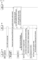
- FIG. 7 is a flow diagram 700 for indicating the change in the MR-DC capability of the UE 700 when the UE 100 is in the connected mode, according to an embodiment as disclosed herein.
- the UE 100 is determined to be in the connected mode at step 408.
- the UE-assistance information comprises an Information Element (IE) indicating the change in the MR-DC capability of the UE (100).
- IE Information Element
- a UE-assistance information message is used for the indication to the eNB 106.
- the UE-assistance information message may perform the following function but not limited to informing the eNB 106 about a power saving preference.
- the eNB 106 may consider that the UE 100 does not prefer a configuration primarily optimised for power saving until the UE 100 explicitly indicates otherwise.
- the UE-assistance information message is used but not limited to indicate the power preference of the UE to the network.
- the method proceeds to step 704 if the UE assistance information is configured to the network and to step 706 if the UE-assistance information is not configured to the network.
- the UE assistance information is sent to update the change in the MR-DC capability of the UE 100.
- FIG. 8 is a sequence diagram for the flow 700 disclosed in FIG. 7 , for indicating the change in the MR-DC capability of the UE 100 when the UE 100 is in the connected mode, and the UE-assistance information is configured to the network, according to an embodiment as disclosed herein.
- the UE 100 is an MR-DC capable UE at step 802, and the UE 100 is in the RRC connected state at step 804.
- the trigger to disable/enable the MR-DC capability of the UE 100 is received by the UE 100 at steps 806 and 808.
- the UE-assistance information is configured to the network.
- the trigger to disable/enable the MR-DC capability of the UE 100 is received.
- the request for change in the MR-DC capability of the UE 100 is sent to the eNB 106 at step 810, and in response the SN 108 is released by the eNB 106 at step 812.
- the RRC connection update is also received by the UE 100 from the eNB 106 at step 814.
- the UE 100 thus is in the idle mode at steps 816 and 818.
- the procedure explained FIGS. 4 and 5a-5b for sending the TAU procedures is followed for the UE 100.
- FIG. 9 is a sequence diagram for conventional method indicating the change in the MR-DC capability of the UE 100 when the UE 100 is in the connected mode, and the UE-assistance information is not configured to the network, according to an embodiment as disclosed herein.
- FIG. 9 explains a scenario where the UE 100 is in the connected mode and is MR-DC enabled. A data path is established for the UE 100, the eNB 106, and the gNB 108. The MR-DC capability of the UE 100 is disabled upon receiving the trigger for disabling the MR-DC capability of the UE 100. As seen in the FIG.
- the MR-DC capability of the UE 100 is disabled/enabled upon occurrence of the local trigger without sending the TAU to the SN 108 and MN 106.
- the disabling/enabling of the MR-DC capability of the UE 100 before sending the TAU procedure results in loss of data from the SN 108 as the change in the MR-DC capability of the SN 108 is not updated and is sending the data to the UE 100.
- the network resources are utilized unnecessarily by the SN for retransmitting as the transmission results into a failure.
- the SN 108 sends SCG reconfiguration messages to the UE 100.
- the UE 100 is unable to recognize the SCG reconfiguration messages sent by the SN 108 as the UE 100 is MR-DC disabled.
- changing the MR-DC capability of the UE 100 before sending the TAU messages to the MN 106 and the SN 108, while the UE 100 is in connected mode results into plurality of disadvantages.
- FIG. 10 is a sequence diagram for conventional method indicating the change in the MR-DC capability of the UE 100 when the UE 100 is in the connected mode, and the UE-assistance information is not configured to the network, according to an embodiment as disclosed herein.
- FIG. 10 explains a scenario where the UE 100 is in the connected mode and is MR-DC enabled.
- the MR-DC capability of the UE 100 is disabled upon receiving the trigger for disabling the MR-DC capability of the UE 100.
- the MR-DC capability of the UE 100 is disabled/enabled upon occurrence of the local trigger after sending the TAU message to the MME 102.
- the MME 102 is aware about the change in the MR-DC capability of the UE 100 due to the TAU messages; however the MN 106 and the SN 108 are not aware of the change in the MR-DC capability.
- the SN 108 sends SCG reconfiguration messages to the UE 100.
- the UE 100 is unable to recognize the SCG reconfiguration messages sent by the SN 108 as the UE 100 is MR-DC disabled.
- changing the MR-DC capability of the UE 100 after sending the TAU messages to the MME 102, while the UE is in connected mode results into plurality of disadvantages.
- FIG. 11 is a sequence diagram for conventional method indicating the change in the MR-DC capability of the UE 100 when the UE 100 is in the connected mode, and the UE-assistance information is not configured to the network, according to an embodiment as disclosed herein.
- FIG. 11 explains a scenario where the UE 100 is in the connected mode and is MR-DC enabled. As seen in the FIG. 11 the trigger to disable the MR-DC capability of the UE 100 is received.
- the TAU messages are sent to the MME 102 indicating the change in the MR-DC capability of the UE 100.
- the UE capability enquiry is sent by the MME 102 and the UE 100 and the response is received. After receiving the response the MR-DC capability of the UE 100 is disabled. However, the SN 108 releases the SCG reconfiguration upon receiving the response that the MR-DC capability of the UE 100 is disabled. This results into RLF as the UE 100 is already MR-DC disabled.
- FIG. 12 is a flow diagram for conventional method indicating the change in the MR-DC capability of the UE 100 when the UE 100 is in the connected mode, according to an embodiment as disclosed herein.
- the figure states that when the local trigger to change the MR-DC capability is received a local RRC release is done.
- the UE 100 enters the idle mode by performing the local RRC release.
- the TAU procedure, an RACH procedure and a security procedure is then sent to the eNB 106 and the MME 102.
- the eNB 106 and the MME 102 are aware of the MR-DC capability change of the UE 100.
- the MR-DC capability of the UE 100 is then disabled. (NR modem is disabled at the UE side).
- the conventional method as explained above has multiple disadvantages and there is no specific method for moving the UE 100 into the idle mode.
- the conventional method results in RLF at the network side. Till the time the RLF is detected at the network side, the network continues to send the data to the device which results in loss of data. This also results in wastage of the network resources. The network has to retransmit those packets which are missed by the UE due to the local release.
- the method as explained in FIG. 13 provides a solution to the problems existing with the conventional methods.
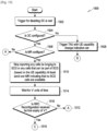
- FIG. 13 is a flow diagram 1300 for the proposed method, when the UE 100 is in the connected mode, according to an embodiment as disclosed herein.
- the trigger for disabling the MR-DC is met.
- the MR-DC capability connectivity regulator 330 determines whether a dual connectivity (DC) for a secondary node (SN) 108 is configured. The method then proceeds to step 1306 if the DC for the SN 108 is configured and to step 1308 if the DC for the SN 108 is not configured.
- DC dual connectivity
- SN secondary node
- the TAU message is triggered indicating the change in the MR-DC capability of the UE.
- a secondary cell group (SCG) failure indication message is triggered.
- SCG secondary cell group
- a timer to receive an acknowledgement of the SCG failure indication message is initiated.
- the MR-DC capability connectivity regulator 330 determines that the timer is expired and the acknowledgement of the SCG failure indication message is not received or the acknowledgement of the SCG failure indication message is received before expiry of the timer.
- the monitoring of the downlink of SN 108 is stopped.
- TAU message comprising the indication of the change in the MR-DC capability of the UE 100 is triggered to the wireless node.
- FIG. 14 is a sequence diagram for method flow 1300, indicating the change in the MR-DC capability of the UE 100 when the UE 100 is in the connected mode, according to an embodiment as disclosed herein.
- the UE is in the RRC connected state at step 1402.
- a trigger to disable the MR-DC capability of the UE 100 is received.
- the SN 108 is configured.
- the trigger to disable the MR-DC capability of the UE 100 is received.
- the UE 100 sends the SCG failure indication to the eNB 106 at step 1404 and waits for an acknowledgement from the SN 108 by imitating the timer.
- the eNB 106 after receiving the SCG failure indication, send the acknowledgement to the UE 100 at step 1406.
- the UE 100 then stops monitoring the downlink for the SCG and the UE 100 is then MR-DC disabled.
- the TAU messages are sent to the MME 102 indicating the change in the MR-DC capability of the UE 100 at step 1408.
- the eNB 106 sends to the MME 102 a message indicating that no UE radio capability information included.
- the MME 102 sends to the eNB 106 a UE radio capability match request.
- the eNB 106 sends to the UE 100 a UE capability enquiry at step 1414, and the UE 100 sends to the eNB 106 UE capability information (MR-DC disable) at step 1416.
- FIG. 15 is a flow diagram 1500 for indicating the change in the MR-DC capability of the UE 100 when the UE 100 is in the connected mode, according to an embodiment as disclosed herein.
- the trigger for disabling the MR-DC is met.
- the MR-DC capability connectivity regulator 330 determines whether a dual capability (DC) for the SN 108 is configured. The method then proceeds to step 1506 if the DC for the SN 108 is configured and to step 1508 if the DC is not configured.
- DC dual capability
- the TAU message is triggered indicating the change in the MR-DC capability of the UE.
- step 1506 it is determined whether an MR is configured for the network or not. The method proceeds to step 1510 if the MR is configured and to step 1512 if the MR is not configured. At step 1510 the reporting of the SCG cells and at least one MR is sent, indicating that no SCG cells are available. At step 1514 a timer is initiated to wait for 'x' units of time. At step 1516 it is determined that the timer is expired and the RRC reconfiguration is received is not received or the RRC reconfiguration is received before expiry of the timer. If the RRC reconfiguration is received before expiry of the ⁇ x' units of time then the method proceeds to step 1518 and if the RRC reconfiguration is not received before expiry of the timer then the step proceeds to step 1512.
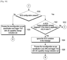
- FIG. 16 is a continuation of flow diagram 1500 of FIG. 15 .
- the RRC reconfiguration is processed as per the specification and the TAU messages is triggered by the TAU trigger comprising the indication of the change in the MR DC capability of the UE.
- the SCG failure indication is already triggered.
- the method proceeds to step 1524 if the SCG failure indication is already triggered and to step 1512 if the SCG failure indication is not triggered.
- the SCG container is ignored.
- the RRC reconfiguration is processed as per the specification and the TAU messages is triggered by the TAU trigger comprising the indication of the change in the MR DC capability of the UE.
- FIG. 17 is a continuation of flow diagram 1500 of FIGS. 15 and 16 .
- FIG. 17 starts with step 1512.
- a SCG failure indication trigger is received.
- the method then proceeds to step 1528.
- step 1528 it is determined that the timer is expired, and the acknowledgement of the SCG failure indication message is not received or the acknowledgement of the SCG failure indication message is received before expiry of the timer at step 1530.
- step 1532 after receiving the acknowledgement the monitoring of the downlink of SN is stopped.
- the TAU message comprising the indication of the change in the MR-DC capability of the UE is triggered to the wireless node.
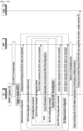
- FIG. 18 is a sequence diagram for method flow 1500, indicating the change in the MR-DC capability of the UE 100 when the UE 100 is in the connected mode, according to an embodiment as disclosed herein.
- the UE is in the RRC connected state.
- a trigger to disable the MR-DC capability of the UE 100 is received.
- the SN 108 is configured.
- the trigger to disable the MR-DC capability of the UE 100 is received.
- the UE 100 sends a Measurement Report (MR) to the eNB indicating that the trigger to disable the MR-DC capability of the UE 100.
- MR Measurement Report
- the UE 100 the sends the SCG failure indication to the eNB 106 and waits for an acknowledgement from the SN 108 by imitating a timer.
- the eNB 106 after receiving the SCG failure indication, send the acknowledgement to the UE 100.
- the UE 100 stops monitoring the downlink for the SCG and the UE 100 is then MR-DC disabled.
- the TAU messages are sent to the MME indicating the change in the MR-DC capability of the UE 100.
- the RACH procedure and the security procedure are then followed as discussed above. As a result of this the data loss from the eNB106 is elimination. Further there is no redundant usage of the network resources.
- the RLF problems are also eliminated by the above discussed method.
- FIG. 19 is a flow diagram 1900 for indicating the change in the MR-DC capability of the UE 100 when the UE 100 is in the connected mode, according to an embodiment as disclosed herein.
- step 1902 it is determined whether SN 108 configuration is present or not. The method is stopped if the SN 108 configuration is not present and proceeds to step 1904 if the SN configuration is present.
- step 1904 the SCG container is ignored in the message and the method is then stopped.
- FIG. 20 is a sequence diagram for the flow 1900 shown in FIG. 19 .
- the UE is in RRC connected state with the eNB 106 at step 2000.
- the trigger to disable the MR-DC of the UE 100 is received at step 2002.
- the UE 100 sends the TAU messages to the MME 102 at step 2004.
- the eNB send enquiry for the UE capability and receives a response by the UE 100.
- the MR-DC capability of the UE 100 is disabled after sending the response at step 2006.
- the RRC reconfiguration is released and the SCG container is ignored in the message.
- the above method eliminates RLF on the MN 106.
- the eNB 106 sends to the MME 102 a message indicating that no UE radio capability information included. Then, at step 2010, the MME 102 sends to the eNB 106 a UE radio capability match request. The eNB 106 sends to the UE 100 an RRC connection reconfiguration (SN related measurements/reconfigurations) at step 2012, and the UE 100 sends to the eNB 106 an RRC reconfiguration complete (ignore SN container) at step 2014.
- RRC connection reconfiguration SN related measurements/reconfigurations
- FIG. 21 is a flow diagram 2100 for indicating the change in the MR-DC capability of the UE 100 when the UE 100 is in the connected mode, according to an embodiment as disclosed herein.
- step 2102 it is determined whether the SN configuration is present or not.
- the method proceeds to step 2104 if the SCG configuration is not present and to step 2106 if the SCG configuration is present.
- step 2104 the UE 100 waits for the capability update procedure to be completed.
- step 2106 it is determined whether the SCG failure indication is already triggered.
- the method proceeds to step 2108 if the SCG failure indication is already triggered and to step 2110 if the SCG failure indication is not triggered.
- step 2108 the SCG container is ignored.
- a secondary cell group (SCG) failure indication message is triggered.
- a timer to receive an acknowledgement of the SCG failure indication message is initiated.
- the monitoring of the downlink of SN is stopped.
- a TAU message comprising the indication of the change in the MR-DC capability of the UE 100 is triggered to the wireless node.
- FIG. 22 is a sequence diagram for the flow 2100 shown in FIG. 21 .
- the UE 100 is in RRC connected state with the eNB 106.
- the trigger to disable the MR-DC of the UE 100 is received.
- the UE 100 sends the TAU messages to the MME.
- the eNB send enquiry for the UE capability and receives a response from the UE 100.
- the MR-DC capability of the UE 100 is disabled after sending the response.
- the RRC reconfiguration is released.
- the SCG failure indication message is triggered and the acknowledgement is received by the UE 100.
- the UE 100 stops monitoring the downlink for the SCG.
- the SN 108 container is ignored.
- the embodiments disclosed herein can be implemented through at least one software program running on at least one hardware device and performing network management functions to control the elements.
- the elements shown in FIGS. 3 through 22 include blocks which can be at least one of a hardware device, or a combination of hardware device and software module.
Landscapes
- Engineering & Computer Science (AREA)
- Computer Networks & Wireless Communication (AREA)
- Signal Processing (AREA)
- Databases & Information Systems (AREA)
- Mobile Radio Communication Systems (AREA)
Claims (11)
- Verfahren zum Angeben einer Änderung einer Multifunkzugriffstechnologie-, RAT, -Dualkonnektivitäts-, MR-DC, -Fähigkeit durch ein Benutzergerät, UE, umfassend:Detektieren, durch das UE, basierend auf einem lokalen Auslöser, einer Änderung der MR-DC-Fähigkeit des UE, die stattgefunden hat;Identifizieren, durch das UE, eines Betriebsmodus des UE, wobei der Betriebsmodus einer von einem Ruhemodus oder einem verbundenen Modus ist;als Reaktion darauf, dass der Betriebsmodus der Ruhemodus ist:
Halten, durch das UE, einer Übertragung einer Verfolgungsbereichsaktualisierungs-, TAU-, Nachricht, Detektieren, durch das UE, eines Ereignisses und Identifizieren einer Gültigkeit der Änderung der MR-DC-Fähigkeit des UE nach dem Detektieren des Ereignisses und Senden einer TAU-Nachricht, die einem ersten Netzknoten Informationen bereitstellt, die angeben, dass die MR-DC-Fähigkeit des UE basierend auf einem Ergebnis der Identifizierung geändert wird; undals Reaktion darauf, dass der Betriebsmodus der verbundene Modus ist:
Identifizieren, durch das UE, ob UE-Unterstützungsinformationen durch den ersten Netzknoten konfiguriert sind, und Auslösen, durch einen TAU-Auslöser (332) des UE, einer Nachricht, die dem ersten Netzknoten die Informationen bereitstellt, die angeben, dass die MR-DC-Fähigkeit des UE basierend auf den UE-Unterstützungsinformationen geändert wird, als Reaktion auf das Identifizieren, dass die UE-Unterstützungsinformationen durch den ersten Netzknoten konfiguriert sind. - Verfahren nach Anspruch 1, wobei das Ereignis ein Ereignis umfasst, das sich auf mindestens eine von einer Anforderung, die von einem Mobilgerät ausgeht, einer Anforderung, die von einem Mobilgerät beendet wird, einer Datenanforderung, einer Signalisierungsanforderung und eine Kurznachrichtendienst-, SMS, -Anforderung bezieht.
- Verfahren nach Anspruch 1, wobei der Betriebsmodus des UE basierend auf dem Ereignis vom Ruhemodus in den verbundenen Modus geändert wird.
- Verfahren nach Anspruch 1, ferner umfassend:Identifizieren, dass ein Auslöser stattgefunden hat; undÜbertragen, an den ersten Netzknoten, der TAU-Nachricht, die die Änderung der MR-DC-Fähigkeit des UE basierend auf dem Auslöser angibt.
- Verfahren nach Anspruch 4, wobei der Auslöser einen Auslöser zum Aufbauen einer Verbindung mit einem zweiten Netzknoten basierend auf einer von einer Anforderung, die von einem Mobilgerät ausgeht, und einer Anforderung, die von einem Mobilgerät beendet wird, beinhaltet.
- Verfahren nach Anspruch 1, wobei das Bereitstellen, für den ersten Netzknoten, der Informationen, die angeben, dass die MR-DC-Fähigkeit des UE basierend auf den UE-Unterstützungsinformationen geändert wird, Folgendes umfasst:Bestimmen, durch das UE, des Deaktivierens der MR-DC-Fähigkeit des UE basierend auf den UE-Unterstützungsinformationen;Übertragen, durch das UE an den ersten Netzknoten, einer Sekundärzellengruppen-, SCG, -Fehlerangabenachricht, die angibt, dass keine Messungen eines Sekundärnetzknotens vorhanden sind;Deaktivieren, durch das UE, der MR-DC-Fähigkeit des UE als Reaktion auf Empfangen eines Antwortsignals für die SCG-Fehlerangabenachricht von dem ersten Netzknoten; undÜbertragen, durch den UE an den ersten Netzknoten, von Informationen, die das Deaktivieren der MR-DC-Fähigkeit des UE angeben.
- Verfahren nach Anspruch 6, wobei das Deaktivieren der MR-DC-Fähigkeit des UE Folgendes umfasst:Bestimmen, durch das UE, ob das Antwortsignal innerhalb einer vorgegebenen Zeit empfangen wird; undDeaktivieren, durch das UE, der MR-DC-Fähigkeit des UE als Reaktion auf das Empfangen des Antwortsignals innerhalb der vorgegebenen Zeit.
- Verfahren nach Anspruch 1, ferner umfassend:als Reaktion darauf, dass der Betriebsmodus der verbundene Modus ist, Übertragen, durch das UE an den ersten Netzknoten, einer Anforderungsnachricht für die Änderung der MR-DC-Fähigkeit des UE;Empfangen, durch das UE vom ersten Netzknoten, einer Antwortnachricht, die angibt, dass eine Verbindung für einen zweiten Netzknoten abgebaut ist; undBereitstellen, durch das UE an den ersten Netzknoten, von Informationen, die die Änderung der MR-DC-Fähigkeit des UE basierend auf der Antwortnachricht angeben.
- Verfahren nach Anspruch 1, ferner umfassend:als Reaktion darauf, dass der Betriebsmodus der verbundene Modus ist, Bestimmen, durch das UE, ob eine Dualkonnektivität, DC, für einen zweiten Netzknoten konfiguriert ist;als Reaktion auf das Bestimmen, dass die DC für den zweiten Netzknoten konfiguriert ist, Bestimmen, durch das UE, des Übertragens von Messungen für den zweiten Netzknoten an den ersten Netzknoten; undBereitstellen, durch das UE an den ersten Netzknoten, von Informationen, die die Änderung der MR-DC-Fähigkeit des UE basierend auf der Bestimmung zum Übertragen der Messungen angeben.
- Benutzergerät, UE (100), Folgendes umfassend:einen Transceiver; undmindestens einen Prozessor (320), der mit dem Transceiver gekoppelt ist und konfiguriert ist zum:Detektieren, basierend auf einem lokalen Auslöser, einer Änderung einer Multifunkzugriffstechnologie-, RAT, -Dualkonnektivitäts-, MR-DC, -Fähigkeit des UE, die stattgefunden hat,Identifizieren eines Betriebsmodus des UE, wobei der Betriebsmodus einer von einem Ruhemodus oder einem verbundenen Modus ist;als Reaktion darauf, dass der Betriebsmodus der Ruhemodus ist:
Halten einer Übertragung einer Verfolgungsbereichsaktualisierungs-, TAU-, Nachricht, Detektieren eines Ereignisses und Identifizieren einer Gültigkeit der Änderung der RAT-MR-DC-Fähigkeit des UE nach dem Detektieren des Ereignisses und Senden einer TAU-Nachricht, die einem ersten Netzknoten Informationen bereitstellt, die angeben, dass die MR-DC-Fähigkeit des UE basierend auf einem Ergebnis der Identifizierung geändert wird, undals Reaktion darauf, dass der Betriebsmodus der verbundene Modus ist:
Identifizieren, ob UE-Unterstützungsinformationen durch den ersten Netzknoten konfiguriert sind, und Auslösen, durch einen TAU-Auslöser (332) des UE, einer Nachricht, die einem ersten Netzknoten die Informationen bereitstellt, die angeben, dass die MR-DC-Fähigkeit des UE basierend auf den UE-Unterstützungsinformationen geändert wird, als Reaktion auf das Identifizieren, dass die UE-Unterstützungsinformationen durch den ersten Netzknoten konfiguriert sind. - UE nach Anspruch 10, wobei der mindestens eine Prozessor (320) ferner konfiguriert ist, um das in einem der Ansprüche 2 bis 9 beschriebene Verfahren durchzuführen.
Applications Claiming Priority (2)
| Application Number | Priority Date | Filing Date | Title |
|---|---|---|---|
| IN201841029151 | 2018-08-02 | ||
| PCT/KR2019/009652 WO2020027616A1 (en) | 2018-08-02 | 2019-08-02 | Method and system for indication of a change in multi-radio access technology dual connectivity capability |
Publications (4)
| Publication Number | Publication Date |
|---|---|
| EP3769580A1 EP3769580A1 (de) | 2021-01-27 |
| EP3769580A4 EP3769580A4 (de) | 2021-06-09 |
| EP3769580C0 EP3769580C0 (de) | 2024-12-25 |
| EP3769580B1 true EP3769580B1 (de) | 2024-12-25 |
Family
ID=69232670
Family Applications (1)
| Application Number | Title | Priority Date | Filing Date |
|---|---|---|---|
| EP19843289.0A Active EP3769580B1 (de) | 2018-08-02 | 2019-08-02 | Verfahren und system zur anzeige einer änderung bei der dualen konnektivitätskapazität einer mehrfunkzugangstechnologie |
Country Status (4)
| Country | Link |
|---|---|
| US (1) | US11425772B2 (de) |
| EP (1) | EP3769580B1 (de) |
| CN (1) | CN112088572B (de) |
| WO (1) | WO2020027616A1 (de) |
Cited By (1)
| Publication number | Priority date | Publication date | Assignee | Title |
|---|---|---|---|---|
| EP3874834A1 (de) * | 2019-06-14 | 2021-09-08 | Google LLC | Einsparen von strom in einer kommunikationsvorrichtung |
Families Citing this family (13)
| Publication number | Priority date | Publication date | Assignee | Title |
|---|---|---|---|---|
| US11317335B2 (en) * | 2019-03-29 | 2022-04-26 | Samsung Electronics Co., Ltd. | Method and apparatus for executing conditional handover in wireless communication network |
| CN113766558B (zh) * | 2019-05-16 | 2025-01-10 | Oppo广东移动通信有限公司 | 一种网络模式控制方法及终端、存储介质 |
| WO2021051247A1 (zh) * | 2019-09-16 | 2021-03-25 | Oppo广东移动通信有限公司 | 测量小区的方法和装置 |
| CN112543477B (zh) * | 2019-09-23 | 2022-04-22 | 北京小米移动软件有限公司 | 测量报告的发送方法、装置、终端及存储介质 |
| US11785657B2 (en) * | 2020-02-24 | 2023-10-10 | Qualcomm Incorporated | UE assistance information for dual connectivity |
| WO2021206506A1 (ko) * | 2020-04-09 | 2021-10-14 | 삼성전자 주식회사 | 백홀 및 액세스 홀 결합 시스템에서 du에게 ip 주소를 할당하는 방법 및 장치 |
| EP4122287B1 (de) * | 2020-04-21 | 2025-07-23 | Google LLC | Verwaltung einer ue-bevorzugten konfiguration |
| WO2021217399A1 (en) * | 2020-04-28 | 2021-11-04 | Qualcomm Incorporated | Recovery from repeated network configuration failure |
| WO2021223053A1 (en) * | 2020-05-05 | 2021-11-11 | Qualcomm Incorporated | Handling repeated radio link failure associated with a dual connectivity mode |
| CN114390640B (zh) * | 2020-10-19 | 2024-02-13 | 大唐移动通信设备有限公司 | 辅小区变换的错误类型的判定方法及设备 |
| KR20220149358A (ko) * | 2021-04-30 | 2022-11-08 | 삼성전자주식회사 | Ue 캐퍼빌리티를 송신하는 전자 장치 및 그 동작 방법 |
| CN115884158B (zh) * | 2021-09-29 | 2025-03-04 | 维沃移动通信有限公司 | Ue的能力变更方法、终端及网络侧设备 |
| KR20240071383A (ko) * | 2021-10-01 | 2024-05-22 | 퀄컴 인코포레이티드 | 이중 연결성 셀 우선순위화 |
Family Cites Families (19)
| Publication number | Priority date | Publication date | Assignee | Title |
|---|---|---|---|---|
| US8972541B2 (en) * | 2010-02-12 | 2015-03-03 | Alcatel Lucent | Method and apparatus providing access network aware presence to applications |
| WO2013091665A1 (en) * | 2011-12-20 | 2013-06-27 | Nokia Siemens Networks Oy | Ue wireless capability change indication |
| EP2621227A1 (de) | 2012-01-27 | 2013-07-31 | Alcatel Lucent | Unterstützung der an ein Mobiltelefon gerichteten Dienstbereitstellung über ein Multi-RAT- und/oder Multidomänennetzwerk |
| US9526091B2 (en) | 2012-03-16 | 2016-12-20 | Intel Corporation | Method and apparatus for coordination of self-optimization functions in a wireless network |
| KR101637370B1 (ko) * | 2012-07-26 | 2016-07-07 | 엘지전자 주식회사 | 2이상의 무선접속기술을 이용한 신호 송수신을 지원하기 위한 방법 및 이를 위한 장치 |
| GB2514843B (en) * | 2013-06-07 | 2015-10-07 | Broadcom Corp | Transceiver reconfiguration mechanism |
| CN105144830B (zh) * | 2013-10-28 | 2019-07-05 | Lg电子株式会社 | 用于在异构网络中执行双重连接的方法和装置 |
| CN105659688B (zh) | 2013-11-01 | 2019-06-18 | Lg电子株式会社 | 用于在异构网络中执行与无线电链路故障有关的操作的方法和设备 |
| CN106134240B (zh) * | 2014-03-21 | 2019-12-13 | 三星电子株式会社 | 用于在支持多个载波的移动通信系统中发送/接收信号的方法和装置 |
| CN106664549B (zh) * | 2014-08-15 | 2020-05-19 | 苹果公司 | 用于性能信息设置的演进节点b和用户设备的方法和装置 |
| ES2989453T3 (es) * | 2014-10-20 | 2024-11-26 | Ericsson Telefon Ab L M | Prohibición de indicaciones de fallo por fallo del grupo de celdas secundario |
| US20170374578A1 (en) * | 2015-02-09 | 2017-12-28 | Nokia Solutions And Networks Oy | Mobility control in dual connectivity operation mode |
| WO2016163723A1 (ko) | 2015-04-05 | 2016-10-13 | 엘지전자(주) | 무선 통신 시스템에서 트래킹 영역 업데이트 타이밍을 조절하기 위한 방법 및 이를 위한 장치 |
| US10560919B2 (en) * | 2015-09-16 | 2020-02-11 | Lg Electronics Inc. | Method for executing paging sequence in wireless communication system, and device for same |
| WO2017164679A1 (ko) | 2016-03-23 | 2017-09-28 | 엘지전자(주) | 무선 통신 시스템에서 트래킹 영역 업데이트 방법 및 이를 위한 장치 |
| US10368393B2 (en) * | 2016-06-10 | 2019-07-30 | Nokia Technologies Oy | Methods and apparatuses for enhancing the setup of carrier aggregation, dual connectivity, multi connectivity, license assisted access, or LTE-WLAN in communications networks |
| US20170367073A1 (en) * | 2016-06-15 | 2017-12-21 | Qualcomm Incorporated | Ue capability exchange for carrier aggregation |
| US20190350027A1 (en) * | 2017-01-11 | 2019-11-14 | Telefonaktiebolaget Lm Ericsson (Publ) | A Radio Access Node, a Core Network Node, an Information Database and Methods of Operating the Same |
| US10595355B2 (en) * | 2017-07-10 | 2020-03-17 | Lg Electronics Inc. | Method and apparatus for establishing a connection in a wireless communication system |
-
2019
- 2019-08-02 US US17/044,823 patent/US11425772B2/en active Active
- 2019-08-02 CN CN201980030586.7A patent/CN112088572B/zh active Active
- 2019-08-02 EP EP19843289.0A patent/EP3769580B1/de active Active
- 2019-08-02 WO PCT/KR2019/009652 patent/WO2020027616A1/en not_active Ceased
Cited By (1)
| Publication number | Priority date | Publication date | Assignee | Title |
|---|---|---|---|---|
| EP3874834A1 (de) * | 2019-06-14 | 2021-09-08 | Google LLC | Einsparen von strom in einer kommunikationsvorrichtung |
Also Published As
| Publication number | Publication date |
|---|---|
| US11425772B2 (en) | 2022-08-23 |
| EP3769580A4 (de) | 2021-06-09 |
| EP3769580C0 (de) | 2024-12-25 |
| WO2020027616A1 (en) | 2020-02-06 |
| CN112088572A (zh) | 2020-12-15 |
| EP3769580A1 (de) | 2021-01-27 |
| US20210185753A1 (en) | 2021-06-17 |
| CN112088572B (zh) | 2024-06-18 |
Similar Documents
| Publication | Publication Date | Title |
|---|---|---|
| EP3769580B1 (de) | Verfahren und system zur anzeige einer änderung bei der dualen konnektivitätskapazität einer mehrfunkzugangstechnologie | |
| US11382167B2 (en) | Prohibiting failure indications for secondary cell group failure | |
| EP3906751B1 (de) | Verwaltung der trägerkonfiguration von benutzergeräten mit en-dc-fähigkeit | |
| US20260089801A1 (en) | Methods and apparatuses for a scg deactivation mechanism and a scg activation mechanism in a mr-dc scenario | |
| US11700553B2 (en) | Method of apparatus for monitoring for a radio link failure associated with a secondary cell of a secondary base station | |
| EP2317795B1 (de) | Verfahren zur verarbeitung der übertragung von näheinformationen und zugehörige kommunikationsvorrichtung | |
| US20240414796A1 (en) | Special Cell Dormancy for New Radio | |
| WO2023197246A1 (en) | Methods and apparatuses for a pscell change or cpac procedure | |
| US20250097797A1 (en) | Methods and apparatuses for mro for pscell change or cpac in nr-u | |
| US10070370B1 (en) | Apparatus, systems and methods for initiating a cell selection | |
| US9763269B2 (en) | Signalling procedures for data transmissions | |
| WO2023164947A1 (en) | Methods and apparatuses for deactivation sn with multiple trps and scg activation failure | |
| US20250056646A1 (en) | Methods and apparatuses for paging enhancement in mt-sdt | |
| WO2022217467A1 (en) | Methods and apparatuses for storing and reporting information relating to a pscell change procedure | |
| US20230308250A1 (en) | Managing cellular radio access technology operations | |
| US10142970B2 (en) | RLC reconfiguration during cell reselection | |
| US20240193014A1 (en) | Methods and apparatuses for reporting event related information | |
| WO2025190473A1 (en) | Sending a message to a network node | |
| GB2627239A (en) | Releasing connection of repeater node from access node | |
| JP2015226295A (ja) | ユーザ装置及び無線リンク障害通知方法 | |
| GB2495142A (en) | Preventing excessively frequent unsuccessful attempts to re-establish access to a network resource |
Legal Events
| Date | Code | Title | Description |
|---|---|---|---|
| STAA | Information on the status of an ep patent application or granted ep patent |
Free format text: STATUS: THE INTERNATIONAL PUBLICATION HAS BEEN MADE |
|
| PUAI | Public reference made under article 153(3) epc to a published international application that has entered the european phase |
Free format text: ORIGINAL CODE: 0009012 |
|
| STAA | Information on the status of an ep patent application or granted ep patent |
Free format text: STATUS: REQUEST FOR EXAMINATION WAS MADE |
|
| 17P | Request for examination filed |
Effective date: 20201020 |
|
| AK | Designated contracting states |
Kind code of ref document: A1 Designated state(s): AL AT BE BG CH CY CZ DE DK EE ES FI FR GB GR HR HU IE IS IT LI LT LU LV MC MK MT NL NO PL PT RO RS SE SI SK SM TR |
|
| AX | Request for extension of the european patent |
Extension state: BA ME |
|
| REG | Reference to a national code |
Ref country code: DE Ref country code: DE Ref legal event code: R079 Ref document number: 602019064043 Country of ref document: DE Free format text: PREVIOUS MAIN CLASS: H04W0076160000 Ipc: H04W0008220000 |
|
| A4 | Supplementary search report drawn up and despatched |
Effective date: 20210507 |
|
| RIC1 | Information provided on ipc code assigned before grant |
Ipc: H04W 8/22 20090101AFI20210430BHEP Ipc: H04W 76/16 20180101ALI20210430BHEP Ipc: H04W 60/04 20090101ALN20210430BHEP Ipc: H04W 76/27 20180101ALN20210430BHEP Ipc: H04W 88/06 20090101ALN20210430BHEP |
|
| DAV | Request for validation of the european patent (deleted) | ||
| DAX | Request for extension of the european patent (deleted) | ||
| STAA | Information on the status of an ep patent application or granted ep patent |
Free format text: STATUS: EXAMINATION IS IN PROGRESS |
|
| 17Q | First examination report despatched |
Effective date: 20230406 |
|
| GRAP | Despatch of communication of intention to grant a patent |
Free format text: ORIGINAL CODE: EPIDOSNIGR1 |
|
| STAA | Information on the status of an ep patent application or granted ep patent |
Free format text: STATUS: GRANT OF PATENT IS INTENDED |
|
| RIC1 | Information provided on ipc code assigned before grant |
Ipc: H04W 88/06 20090101ALN20240704BHEP Ipc: H04W 76/27 20180101ALN20240704BHEP Ipc: H04W 60/04 20090101ALN20240704BHEP Ipc: H04W 76/16 20180101ALI20240704BHEP Ipc: H04W 8/22 20090101AFI20240704BHEP |
|
| INTG | Intention to grant announced |
Effective date: 20240716 |
|
| GRAS | Grant fee paid |
Free format text: ORIGINAL CODE: EPIDOSNIGR3 |
|
| GRAA | (expected) grant |
Free format text: ORIGINAL CODE: 0009210 |
|
| STAA | Information on the status of an ep patent application or granted ep patent |
Free format text: STATUS: THE PATENT HAS BEEN GRANTED |
|
| AK | Designated contracting states |
Kind code of ref document: B1 Designated state(s): AL AT BE BG CH CY CZ DE DK EE ES FI FR GB GR HR HU IE IS IT LI LT LU LV MC MK MT NL NO PL PT RO RS SE SI SK SM TR |
|
| REG | Reference to a national code |
Ref country code: GB Ref legal event code: FG4D |
|
| REG | Reference to a national code |
Ref country code: CH Ref legal event code: EP |
|
| REG | Reference to a national code |
Ref country code: DE Ref legal event code: R096 Ref document number: 602019064043 Country of ref document: DE |
|
| REG | Reference to a national code |
Ref country code: IE Ref legal event code: FG4D |
|
| U01 | Request for unitary effect filed |
Effective date: 20250107 |
|
| U07 | Unitary effect registered |
Designated state(s): AT BE BG DE DK EE FI FR IT LT LU LV MT NL PT RO SE SI Effective date: 20250115 |
|
| PG25 | Lapsed in a contracting state [announced via postgrant information from national office to epo] |
Ref country code: HR Free format text: LAPSE BECAUSE OF FAILURE TO SUBMIT A TRANSLATION OF THE DESCRIPTION OR TO PAY THE FEE WITHIN THE PRESCRIBED TIME-LIMIT Effective date: 20241225 |
|
| PG25 | Lapsed in a contracting state [announced via postgrant information from national office to epo] |
Ref country code: NO Free format text: LAPSE BECAUSE OF FAILURE TO SUBMIT A TRANSLATION OF THE DESCRIPTION OR TO PAY THE FEE WITHIN THE PRESCRIBED TIME-LIMIT Effective date: 20250325 |
|
| PG25 | Lapsed in a contracting state [announced via postgrant information from national office to epo] |
Ref country code: GR Free format text: LAPSE BECAUSE OF FAILURE TO SUBMIT A TRANSLATION OF THE DESCRIPTION OR TO PAY THE FEE WITHIN THE PRESCRIBED TIME-LIMIT Effective date: 20250326 |
|
| PG25 | Lapsed in a contracting state [announced via postgrant information from national office to epo] |
Ref country code: RS Free format text: LAPSE BECAUSE OF FAILURE TO SUBMIT A TRANSLATION OF THE DESCRIPTION OR TO PAY THE FEE WITHIN THE PRESCRIBED TIME-LIMIT Effective date: 20250325 |
|
| PG25 | Lapsed in a contracting state [announced via postgrant information from national office to epo] |
Ref country code: SM Free format text: LAPSE BECAUSE OF FAILURE TO SUBMIT A TRANSLATION OF THE DESCRIPTION OR TO PAY THE FEE WITHIN THE PRESCRIBED TIME-LIMIT Effective date: 20241225 |
|
| PG25 | Lapsed in a contracting state [announced via postgrant information from national office to epo] |
Ref country code: PL Free format text: LAPSE BECAUSE OF FAILURE TO SUBMIT A TRANSLATION OF THE DESCRIPTION OR TO PAY THE FEE WITHIN THE PRESCRIBED TIME-LIMIT Effective date: 20241225 |
|
| PG25 | Lapsed in a contracting state [announced via postgrant information from national office to epo] |
Ref country code: ES Free format text: LAPSE BECAUSE OF FAILURE TO SUBMIT A TRANSLATION OF THE DESCRIPTION OR TO PAY THE FEE WITHIN THE PRESCRIBED TIME-LIMIT Effective date: 20241225 |
|
| PG25 | Lapsed in a contracting state [announced via postgrant information from national office to epo] |
Ref country code: IS Free format text: LAPSE BECAUSE OF FAILURE TO SUBMIT A TRANSLATION OF THE DESCRIPTION OR TO PAY THE FEE WITHIN THE PRESCRIBED TIME-LIMIT Effective date: 20250425 |
|
| PG25 | Lapsed in a contracting state [announced via postgrant information from national office to epo] |
Ref country code: SK Free format text: LAPSE BECAUSE OF FAILURE TO SUBMIT A TRANSLATION OF THE DESCRIPTION OR TO PAY THE FEE WITHIN THE PRESCRIBED TIME-LIMIT Effective date: 20241225 |
|
| PG25 | Lapsed in a contracting state [announced via postgrant information from national office to epo] |
Ref country code: CZ Free format text: LAPSE BECAUSE OF FAILURE TO SUBMIT A TRANSLATION OF THE DESCRIPTION OR TO PAY THE FEE WITHIN THE PRESCRIBED TIME-LIMIT Effective date: 20241225 |
|
| U20 | Renewal fee for the european patent with unitary effect paid |
Year of fee payment: 7 Effective date: 20250822 |
|
| PGFP | Annual fee paid to national office [announced via postgrant information from national office to epo] |
Ref country code: GB Payment date: 20250722 Year of fee payment: 7 |
|
| PLBE | No opposition filed within time limit |
Free format text: ORIGINAL CODE: 0009261 |
|
| STAA | Information on the status of an ep patent application or granted ep patent |
Free format text: STATUS: NO OPPOSITION FILED WITHIN TIME LIMIT |
|
| REG | Reference to a national code |
Ref country code: CH Ref legal event code: L10 Free format text: ST27 STATUS EVENT CODE: U-0-0-L10-L00 (AS PROVIDED BY THE NATIONAL OFFICE) Effective date: 20251105 |
|
| 26N | No opposition filed |
Effective date: 20250926 |
|
| REG | Reference to a national code |
Ref country code: CH Ref legal event code: H13 Free format text: ST27 STATUS EVENT CODE: U-0-0-H10-H13 (AS PROVIDED BY THE NATIONAL OFFICE) Effective date: 20260324 |
|
| PG25 | Lapsed in a contracting state [announced via postgrant information from national office to epo] |
Ref country code: MC Free format text: LAPSE BECAUSE OF FAILURE TO SUBMIT A TRANSLATION OF THE DESCRIPTION OR TO PAY THE FEE WITHIN THE PRESCRIBED TIME-LIMIT Effective date: 20241225 |
|
| PG25 | Lapsed in a contracting state [announced via postgrant information from national office to epo] |
Ref country code: CH Free format text: LAPSE BECAUSE OF NON-PAYMENT OF DUE FEES Effective date: 20250831 |